

Page 1
RESIDENTIAL FLOOR BOX
INSTALLATION INSTRUCTIONS
These INSTALLATION INSTRUCTIONS cover:
Cat. No. 78WRB Recessed Floor Box with Brass Cover
78WRN Recessed Floor Box with Nickel Cover
WARNING
ELECTRICAL HAZARD!
BE SURE POWER IS OFF!
Floor Box should be installed by a
qualified electrician in accordance with
national and local electrical codes.
CAUTION
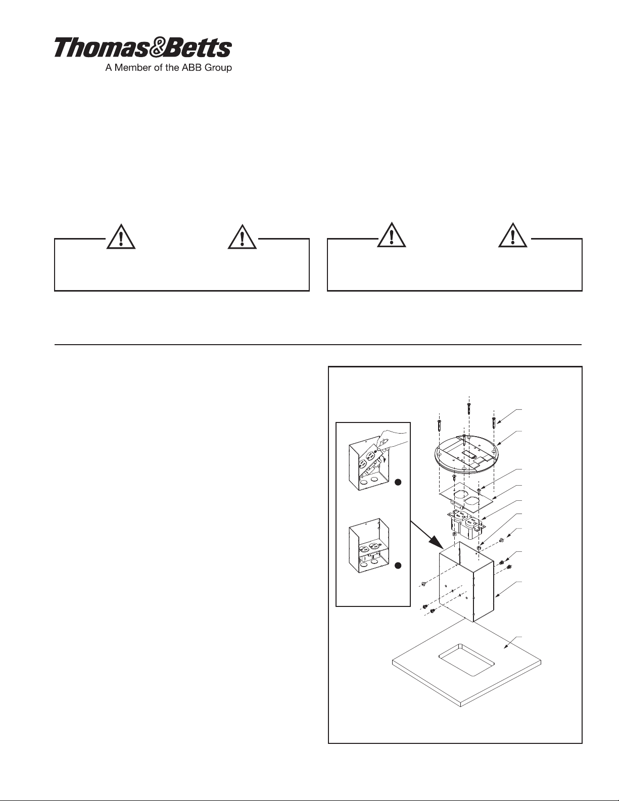
— Residential Floor Box shown with Duplex receptacle and Cover Plate. —
IMPORTANT: Read all instructions before installing any 78W Series Residential Floor Boxes.
Residential Floor Box shown with
Duplex receptacle and Cover Plate
Installation:
1). Select desired location for the Floor Box.
Do not install directly over floor joists!
2). Cut an opening into floor using the Template.
(See Figure 4)
Notice: Maintain the size of the opening within template
to ensure full coverage of the opening by cover.
3). Open KO's in Steel Box as required.
4). Pull electrical conductors up though the opening in
sub-floor into Steel Box.
5). Use appropriate strain relief fittings and secure
conductors to floor box.
Note: strain relief furnished for non-metallic
sheathed cable only.
6). Make all electrical connections to Duplex receptacle per
National and Local Electrical Codes. (See Figure 2)
7). Secure receptacle to Middle Plate using screws
provided with receptacle and nuts.
8). Place Middle Plate with receptacle in the steel box and
install it using (4) middle plate screws.
9). Attach Cover to Steel Box using (2) cover screws. And
place Cover Gasket underneath Cover.
Pre-drill 4 holes with 1/8” drill bit using cover as a template.
10).
Insert Floor Box though opening and secure it with (4) wood
screws on top of finished floor covering (carpet, wood, or tile).
© 2015 Thomas & Betts. All Rights Reserved.
Insert Middle Plate
with receptacle into
Steel Box diagonally.
Then press the
raised end.
FIGURE 1
FIGURE 1
1
2
(4) Wood
Screws
Cover Plate
(2) Receptacle
Screws
Middle Plate
Receptacle
(2) Receptacle
Nuts
(2) Cover
Screws
(4) Middle Plate
Screws
Steel Box
Sub-Floor
TA04819 A
Page 1 of 2
Page 2

Split Circuit Tab
Hot
(Black )
Brass
FIGURE 2
Ground
(Green Or Bare )
Green Screw
Neutral
(White)
Silver
SCALE: 1:1
3-1/16”
3/8”
Lid Cover Moved
Electrical Cord
Cord Opening
When a cord is plugged into the receptacle away
from the cord opening, loop the cord so that it exits
the cord opening vertically.
FIGURE 3
4-13/16”
Floor Opening Template
Use this guide to punch drill bit centers;
use a center punch or nail set.
FIGURE 4
WARRANTY: Thomas & Betts sells this product with the understanding that the user will perform all necessary tests to
determine the suitability of this product for the user's intended application. Thomas & Betts warrants that this product will be
free from defects in materials or workmanship for a period of two (2) years following the date of purchase. Upon prompt
notication of any warranted defect, Thomas & Betts will, at its option, repair or replace the defective product. Misuse,
misapplication or modication of Thomas & Betts Products immediately voids all warranties.
Limitations and Exclusions: THE ABOVE WARRANTY IS THE SOLE WARRANTY CONCERNING THIS PRODUCT, AND IS
IN LIEU OF ALL OTHER WARRANTIES EXPRESS OR IMPLIED, INCLUDING BUT NOT LIMITED TO ANY IMPLIED
WARRANTY OF MERCHANTABILITY OR FITNESS FOR A PARTICULAR PURPOSE, WHICH ARE SPECIFICALLY
DISCLAIMED. LIABILITY FOR BREACH OF THE ABOVE WARRANTY IS LIMITED TO COST OF REPAIR OR
REPLACEMENT OF THE PRODUCT, AND UNDER NO CIRCUMSTANCES WILL THOMAS & BETTS BE LIABLE FOR
ANY INDIRECT, SPECIAL, INCIDENTAL OR CONSEQUENTIAL DAMAGES.
TA04819 A
Page 2 of 2
© 2015 Thomas & Betts. All Rights Reserved.
 Loading...