

Page 1
INSTALLATION INSTRUCTIONS
FOR CONCEALED SERVICE FLOOR BOX
Catalog Number: 665-AV2
IMPORTANT: Read all instructions before installing oor box, carpet plate or mounting kit.
WARNING
ELECTRICAL HAZARD!
BE SURE POWER IS OFF!
MINIMUM CONCRETE DEPTH FOR THE
665-AV2 FLOOR BOX IS: 4-1/2” DEEP
INSTALLATION INSTRUCTIONS
(BEFORE CONCRETE POUR)
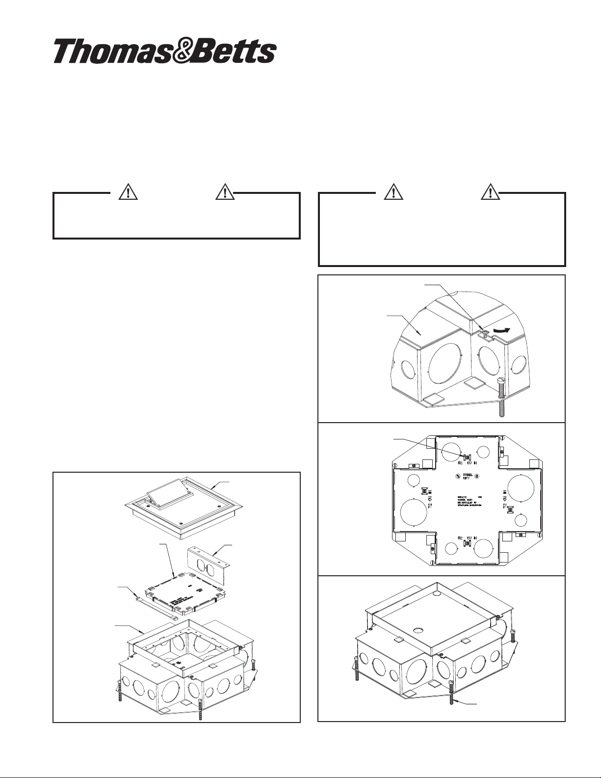
1. Remove the top of box, loosen (4) top screws and
rotate top plate away from screws. See gure 2.
2. Install (4) ground screws. See gure 3.
3. Install conduit connectors as needed.
4. Break/trim off partition from non-metallic tunnel.
Place non-metallic tunnel and partition in box.
See gure 1.
5. Install (4) leveling screws. See gure 4.
6. Replace top and tighten (4) top screws. See gure 4.
7. Adjust leveling screws so that top edge of box is
1/16” below screed line. Attach conduit and secure
box to form. See gure 4. Box is now ready for
concrete pour.
CAUTION
FLOOR BOX SHOULD BE INSTALLED
BY A QUALIFIED ELECTRICIAN IN
ACCORDANCE WITH NATIONAL AND
LOCAL ELECTRICAL CODES.
LOOSEN SCREWS
ROTATE PLATE
TOP PLATE
Figure 2
INSTALL GROUND
SCREW (4-PLACES)
(FURNISHED)
665-AV2
ASSEMBLY
NON-METALLIC
WIRING TUNNEL
PARTITION
(Save for STEP 10)
665-AV2
FLOOR BOX
Figure 1
665-CST
(NOT-INCLUDED
DEVICE PANEL
(NOT INCLUDED)
Figure 3
Figure 4
LEVELING SCREWS
(FURNISHED)
TA04486 A Page 1 of 2
Page 2
ACTIVATION INSTRUCTIONS
(AFTER CONCRETE POUR)
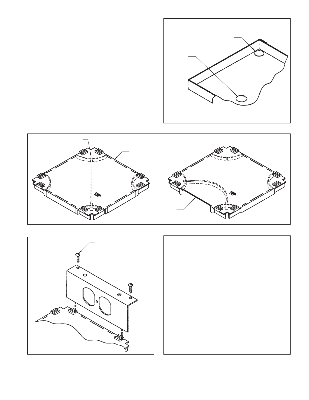
8. Remove concrete from access frame. Break off
plastic retainers (2) and use knockout to remove
plate. See gure 5.
9. Install devices in accordance with N.E.C and
prevailing local electrical codes.
10. Place non-metallic tunnel in box on top of separate
services by removing selected tabs for feed through.
Use the snap-in partition (step 4) to isolate low
power service or to close an open tab. See gure 6.
11. Install the device panels by locating the bottom edge
in the locking tabs on the non-metallic tunnel and
securing the top with the (2) #6-32 screws furnished
with each device plate. See gure 7.
12.
Complete the activation with the 665-CST cover
using the (4) #8-32 screws furnished with each cover.
PARTITION MAY BE
USED TO SEPARATE
SERVICES
REMOVABLE TABS
FOR WIRE FEED
REMOVE RETAINERS
PRY HERE
Figure 5
Figure 6
Figure 7
#6-32 SCREW
PARTITION USED TO
CLOSE AN OPEN TAB
WARRANTY: Thomas & Bett s sells this product with the
understa nding that the u ser wi ll p erform all n ecessary tests to
determin e the su itability of this product for the user’s int ended
applicat ion. Thoma s & Betts warr ants that thi s product w ill be
free fro m defects i n materials and workmanship for a period
of two (2) years followi ng th e d ate o f pur chase. Upon prompt
noticat ion of any warranted d efect, Thom as & Bett s will, a t
its optio n, repair or replace the defective product or refund
the purchas e p rice. Proof of purchas e i s req uired. Misuse or
unauthor ized modi cation of the product voids al l warrantie s.
Limitations and Exclusions: THE ABOVE WARRANTY IS THE
SOLE WARRANTY CONCERNING THIS PRODUCT, AND IS IN
LIEU OF ALL OTHER WARRANTIES EXPRESS OR IMPLIED,
INCLUDING BUT NOT LIMITED TO ANY IMPLIED WARRANTY
OF MERCHANTABILITY OR FITNESS FOR A PARTICULAR
PURPOSE, WHICH ARE SPECIFICALLY DISCLAIMED. LIABILITY
FOR BREACH OF THE ABOVE WARRANTY IS LIMITED TO COST
OF REPAIR OR REPLACEMENT OF THE PRODUCT, AND UNDER
NO CIRCUMSTANCES WILL THOMAS & BETTS BE LIABLE FOR
ANY INDIRECT, SPECIAL, INCIDENTAL OR CONSEQUENTIAL
DAMAGES.
Thomas & Betts Corporation • Memphis, Tennessee • www.tnb.com
© 2009 Thomas & Betts. All Rights Reserved.
TA04486 A Page 2 of 2
 Loading...