

Thomas ultra air-pacT-35HD Owner's Manual
1419 ILLINOIS AVE., SHEBOYGAN, WI 53081 USA (920) 457-4891
OWNER'S MANUAL
and
OPERATING INSTRUCTIONS
for
Model
T-35HD
Portable, Oilless Heavy Duty Air Compressor
W0B.L PISTON COMPRESSOR
GENERAL
DESCRIPTION
Performance in tandem with portability makes the Air-Pac
T-35
Ultra
our finest, most convenient tank compressor which is perfect for the
professional and serious do-it-yourselfer. This compressor includes
air storage tank, and an automatic pressure switch control.
SPECIFICATIONS
Voltage
.....................................................................
11
5V,
60Hz
Starting Voltage (min.)
.....................................................
90
V
Fuse Requirements
............................................................
15
A
Safety Valve Setting
..............................
140
PSlG
(965.3
KPa)
Air Displacement
.......................................
4.5
CFM
(127
LPM)
Air Delivery
................................................
2.95
CFM @ 50
PSI
........................................................
(83.54
LPM @ 345
KPa)
................................................................
2.65
CFM @ 80
PSI
........................................................
(75.05
LPM @ 552
KPa)
..............................................................
2.55
CFM @ 100
PSI
.....................................................
(72.22
LPM @ 689.5
KPa)
Amps at Working Pressure
........................................
10 5
A
.....................................
Automatic Control
Starts
@
100
PSlG
.............................................................................
(689.5
KPa)
.................................................................
Stops @ 125
PSlG
.............................................................................
(861.9
KPa)
..........................................................................
Tank Size
3
Gal.
.............................................................
Shipping Weight
48
Ibs.
........................................................................
Cord
6
ft.
(1.83
M)
PSI
=
Pounds Per Square Inch CFM = Cubic Feet Per Minute
KPa = Kilopascals
LPM
=
Liters Per Minute
APPLICATION
Ideal as primary or secondary air source for almost any
operation. Particularly suitable for shops, garages; and
factories where repetitive use demands high reliability.
purchased the compressor.
To place parts orders, provide the model data located
on the nameplate of the compressor and call our
National Parts center at
1-800-323-0620.
GENERAL MAINTENANCE AND SERVICE
A
WARNING:
Read and understand the information in this
owner's manual before operating
air compressor.
1.
The compressor should be located in a dry, clean, and well
ventilated area.
2.
Inspect before use: hose, plug, and cord for signs of damage.
Do not use if a deficiency is found. Contact your nearest service
center for replacement parts. Never operate a damaged unit.
3.
Do not tamper with safety valve as it has been factory set.
Any adjustment with this valve could cause serious injury.
4.
This air compressor needs no lubrication. Applying oil to any
part could result in polluted air delivery to the air-handling
equipment.
5.
Compressed air must never be aimed at anyone because it can
cause serious injury. Keep children away. WEAR EYE
PROTECTION.
6.
All air compressors generate heat even under normal operating
conditions. To avoid serious burns, never touch the air compres
sor during or immediately after operation.
7.
When unit is not in use, wrap cord around compressor and store
in dry place. Do not abuse cord.
8.
Before servicing, cleaning, or removal of any part, shut off power
and relieve pressure from tank.
9.
This system produces
125
PSI. To avoid rupture and injury, do
not operate this pump with components rated less than
125
PSI
working pressure (including but not limited to spray guns, hose
and hose connections without pressure regulator).
If warranty service or repair is needed contact your nearest
authorized service center. If one does not exist contact the
factory. Unauthorized repairs or
teardown of the unit will void
factory warranty.
Part
No.
642143
Rev. H 7/01 01994
Thomas
Industries
Inc.,
Printed in
U.S.A.
All
Rights Resewed
SETUP
Location of Air Compressor
Operate air compressor in a clean, dry and well ventilated area. The
air filter must be kept clear of obstructions which could reduce air
flow to the compressor. The air compressor should be located at
least 12" away from walls or other obstructions that could interfere
with the flow of air.
Extension Cords
To avoid voltage drop and power loss to motor, use additional hose
instead of an extension cord. If an extension cord must be used, use
only a 3-wire extension cord equipped with a 3-blade grounding plug
and a 3-slot receptacle that will accept the plug on the compressor.
Be sure to use an extension cord heavy enough to carry the current
your product will draw. An undersized cord will cause a drop in line
voltage resulting in loss of power and overheating. Make sure the
extension cord is in aood condition.
NOTE: Wire size increases as gauge number decreases.
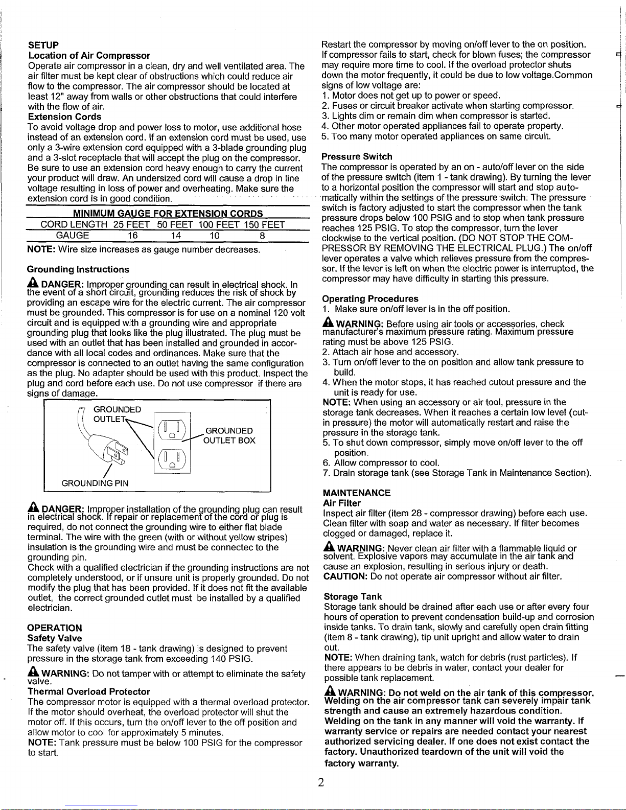
Grounding Instructions
A
DANGER: Improper groundin can result in electrical shock. In
the event of a short circuit,
groun!ing reduces the risk of shock by
providing an escape wire for the electric current. The air compressor
must be grounded. This compressor is for use on a nominal 120 volt
circuit and is equipped with a grounding wire and appropriate
grounding plug that looks like the plug illustrated. The plug must be
used with an outlet that has been installed and grounded in accordance with all local codes and ordinances. Make sure that the
compressor is connected to an outlet having the same configuration
as the plug. No adapter should be used with this product. lnspect the
plug and cord before each use. Do not use compressor if there are
signs of damage.
I
n
GROUNDED
I
/
I
GROUNDING PIN
A
DANGER: Im ro er installation of the rounding plug can result
in electrical shock
l?repair or replacemenfof the cord or plug is
required, do not connect the grounding wire to either flat blade
terminal. The wire with the green (with or without yellow stripes)
insulation is the grounding wire and must be connectec to the
grounding pin.
Check with a qualified electrician if the grounding instructions are not
completely understood, or if unsure unit is properly grounded. Do not
modify the plug that has been provided. If it does not fit the available
outlet, the correct grounded outlet must be installed by a qualified
electrician.
OPERATION
Safety Valve
The safety valve (item 18
-
tank drawing) is designed to prevent
pressure in the storage tank from exceeding 140 PSIG.
A
WARNING: Do not tamper with or attempt to eliminate the safety
-
valve.
Thermal Overload Protector
The compressor motor is equipped with a thermal overload protector.
If the motor should overheat, the overload protector will shut the
motor off. If this occurs, turn the onloff lever to the off position and
allow motor to cool for approximately
5
minutes.
NOTE: Tank pressure must be below 100 PSIG for the compressor
to start.
Restart the compressor by moving onloff lever to the on position.
If compressor fails to start, check for blown fuses; the compressor
may require more time to cool. If the overload protector shuts
down the motor frequently, it could be due to low
voltage.Common
signs of low voltage are:
1. Motor does not get up to power or speed.
2.
Fuses or circuit breaker activate when starting compressor.
3. Lights dim or remain dim when compressor is started.
4. Other motor operated appliances fail to operate property.
5. Too many motor operated appliances on same circuit.
Pressure Switch
The compressor is operated by an on
-
autoloff lever on the side
of the pressure switch (item 1 -tank drawing). By turning the lever
to a horizontal position the compressor will start and stop automatically within the settings of the pressure switch. The pressure
switch is factory adjusted to start the compressor when the tank
pressure drops below 100 PSIG and to stop when tank pressure
reaches 125 PSIG. To stop the compressor, turn the lever
clockwise to the vertical position. (DO NOT STOP THE COMPRESSOR BY REMOVING THE ELECTRICAL PLUG.) The onloff
lever operates a valve which relieves pressure from the compressor. If the lever is left on when the electric power is interrupted, the
compressor may have difficulty in starting this pressure.
Operating Procedures
1. Make sure onloff lever is in the off position.
A
WARNING: Befqre using air tools or acces~ories, check
manufacturer's maximum pressure rating. Maximum pressure
rating must be above 125 PSIG.
2.
Attach air hose and accessory.
3.
Turn onloff lever to the on position and allow tank pressure to
build.
4.
When the motor stops, it has reached cutout pressure and the
unit is ready for use.
NOTE: When using an accessory or air tool, pressure in the
storage tank decreases. When it reaches a certain low level
(cutin pressure) the motor will automatically restart and raise the
pressure in the storage tank.
5.
To shut down compressor, simply move onloff lever to the off
position.
6.
Allow compressor to cool.
7.
Drain storage tank (see Storage Tank in Maintenance Section).
MAINTENANCE
Air Filter
lnspect air filter (item 28
-
compressor drawing) before each use.
Clean filter with soap and water as necessary. If filter becomes
clogged or damaged, replace it.
A
WARNING:.N~~~~ clean air filter with a flammable li uid or
solvent. Explosive vapors may accumulate
in the as tan% and
cause an explosion, resulting in serious injury or death.
CAUTION: Do not operate air compressor without air filter.
Storage Tank
Storage tank should be drained after each use or after every four
hours of operation to prevent condensation build-up and corrosion
inside tanks. To drain tank, slowly and carefully open drain fitting
(item 8 -tank drawing), tip unit upright and allow water to drain
out.
NOTE: When draining tank, watch for debris (rust particles). If
there appears to be debris in water, contact your dealer for
possible tank replacement.
A
WARNING: Do not weld on the air tank of this compressor.
Welding on the air compressor tank can severely impair tank
strength and cause an extremely hazardous condition.
Welding on the tank in any manner will void the warranty. If
warranty service or repairs are needed contact your nearest
authorized servicing dealer. If one does not exist contact the
factory. Unauthorized
teardown of the unit will void the
factory warranty.

 Loading...