

Page 1
Part No. 642485 Rev. H 08/08 ©2006 Gardner Denver Thomas Inc.,
Printed in U.S.A. All Rights Reserved
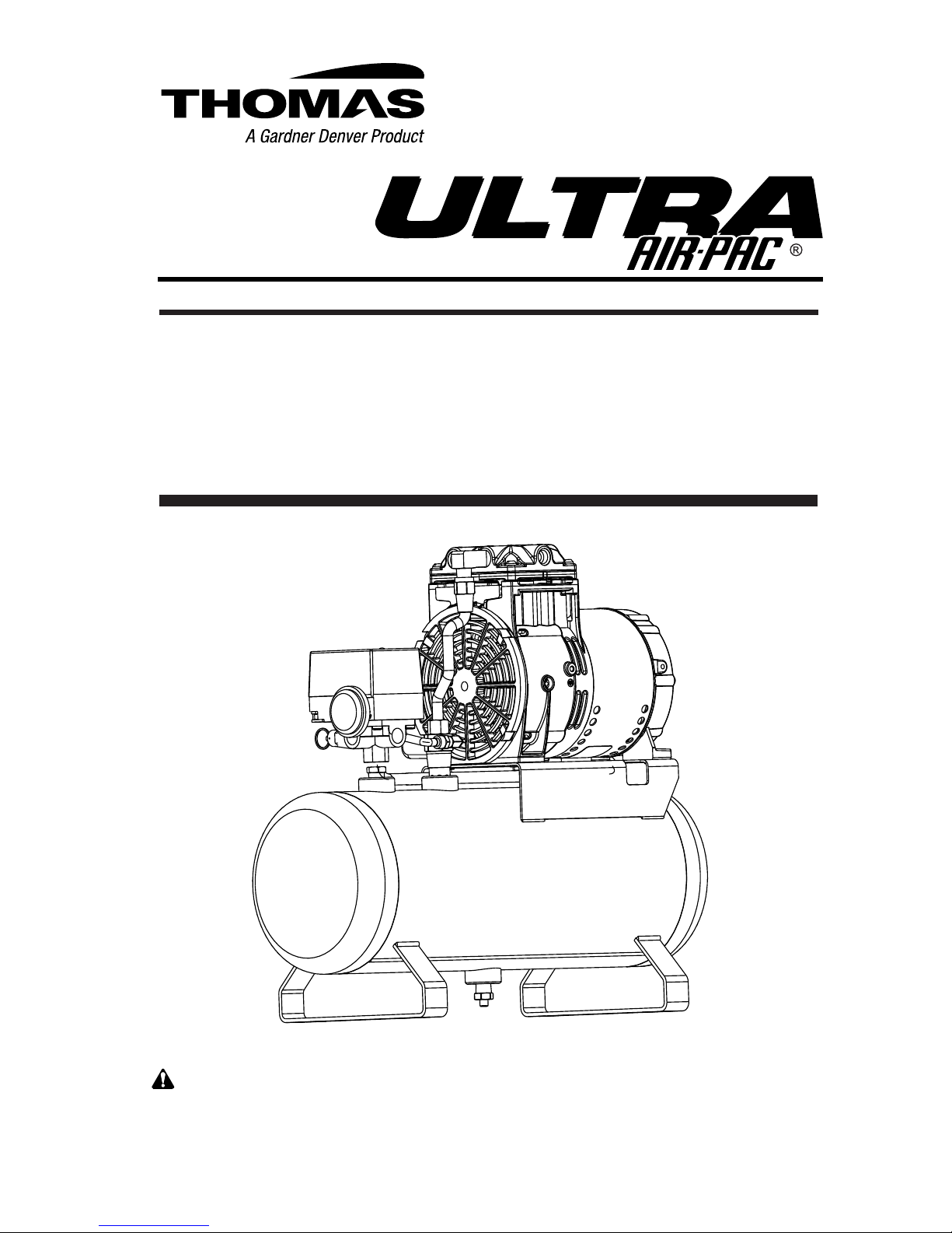
OWNER’S MANUAL and OPERATING INSTRUCTIONS for
Portable, Perma-Lube™ Heavy Duty
WOB•L PISTON AIR COMPRESSOR
Model T-617HDN
3524 WASHINGTON AVE., SHEBOYGAN, WI 53081 USA 1-800-558-7721 www.thomasairpac.com
WARNING: Read and understand the information in this
owner’s manual before operating air compressor.
Page 2

TABLE OF CONTENTS
Page #
General Description.......................................................... 1
Application......................................................................... 1
Safety................................................................................. 2
Set-Up................................................................................ 3
Operating Instructions..................................................... 4
Maintenance...................................................................... 6
Spanish Language Instructions....................................... 7
Exploded View & Parts List............................................. 10
French Language Instructions........................................ 15
Compressor Troubleshooting......................................... 21
Limited Warranty.............................................................. 22
Page 3

1
GENERAL DESCRIPTION
The Airpac model T-617HDN is an electrically powered air compressor
with a thermally protected motor, mounted to a 2 gallon air storage tank.
Tank pressure is regulated by a combination of a pressure switch and a
safety valve. The pressure switch will turn the compressor on when tank
pressure drops below 100 PSIG, and turn the compressor off when tank
pressure reaches 122 PSIG. The safety valve prevents tank pressure
from exceeding 140 PSIG.
SPECIFICATIONS
Voltage .............................................................................................. 115V, 60Hz
Fuse Requirements..................................................................................... 10A
Safety Valve Setting .......................................................... 140 PSIG (965 KPa)
Air Displacement .............................................................. 1.75 CFM (49.5 LPM)
Air Delivery .......................................................................... .90 CFM @ 100 PSI
.............................................................................. (25.48 LPM @ 689.5 KPa)
Amps at Working Pressure ........................................................................ 3.9 A
Automatic Control ................................................................. Starts @ 98 PSIG
...................................................................................................... (675.7 KPa)
.......................................................................................... Stops @ 122 PSIG
...................................................................................................... (841.2 KPa)
Tank Size .............................................................................................. 2 Gal.
Shipping Weight........................................................................................ 32 Ibs.
Cord ................................................................................................. 6 ft. (1.83 M)
Sound Level .............................................................................................. 60 dB
PSI = Pounds Per Square Inch CFM = Cubic Feet Per Minute
KPa = Kilopascals LPM = Liters Per Minute
APPLICATION
Ideal as primary or secondary air source for almost any operation, the
Renegade T-617HDN is particularly suitable for shops, garages, and
factories where repetitive use demands high reliability. The
T-617HDN will operate:
1 Finish Nail Guns
Visit www.thomasairpac.com for more information
Page 4

SAFETY FIRST
1. The compressor should be located in a dry, clean, and well ventilated
area.
2. Inspect hose, plug, and cord for signs of damage before use. Do not use
if a deciency is found. Contact your nearest service center for replacement
parts. Never operate a damaged unit.
3. Do not tamper with the safety valve. It has been factory set. Any
adjustment of this valve could cause serious injury.
4. This air compressor needs no lubrication. Applying oil to any part could result
in polluted air delivery to the air-handling equipment.
5. Compressed air must never be aimed at anyone because it can cause serious
injury. Keep children away. WEAR EYE PROTECTION.
6. All air compressors generate heat even under normal operating conditions.
To avoid serious burns, never touch the air compressor during or immediately
after operation.
7. When unit is not in use, wrap cord securely and store in dry place. Do not
abuse cord or plug.
8. Before servicing, cleaning, or removal of any part, shut off power and relieve
pressure from tank.
9. This system produces 125 PSI. To avoid rupture and injury, do not operate
this pump with components rated less than 125 PSI working pressure (including
but not limited to spray guns, hose and hose connections without pressure
regulator).
If warranty service or repair is needed contact your nearest
authorized service center. If one does not exist in your area,
contact the factory. Unauthorized repairs or teardown of the
unit will void the factory warranty.
This symbol points out important safety instructions which
if not followed could endanger the personal safety and/or
property of yourself and others. Read and understand the
information in this owner’s manual and the engine owners
manual before operating.
2
Page 5

SET-UP
Location of Air Compressor
Operate air compressor in a clean, dry and well ventilated area. The air lter
must be kept clear of obstructions which could reduce air ow to the compressor.
The air compressor should be located at least 12” away from walls or other
obstructions that could interfere with the ow of air.
1. Remove the air compressor from the carton and
place it on its side.
2. Install the 4 rubber feet with the screws
included in the accessory kit as shown.
3. Close the tank drain valve.
4. Remove 2 head screws and install handle
with hardware included in accessory kit.
5. Turn on/auto/off lever on the pressure switch
to the “OFF” position.
6. Attach air hose to the compressor manifold.
7. Plug the power cord into a grounded outlet
or approved extension cord. (See Grounding
Instruction section) Turn the on/auto/off lever
on the pressure switch to the “ON” position.
Extension Cords
To avoid voltage drop and power loss to motor, use additional hose instead
of an extension cord. If an extension cord must be used, use only a 3-wire
extension cord equipped with a 3-blade grounding plug and a 3-slot receptacle
that will accept the plug on the compressor. Be sure to use an extension cord
heavy enough to carry the current your product will draw. An undersized cord
will cause a drop in line voltage resulting in loss of power and overheating.
Make sure the extension cord is in good condition.
NOTE: Wire size increases as gauge number decreases.
3
MINIMUM GAUGE FOR EXTENSION CORDS
CORD LENGTH 25 FEET 50 FEET 100 FEET 150 FEET
GAUGE 12 12 10 8
tank drain
valve
attach feet
(2) each side
attach air hose
Page 6
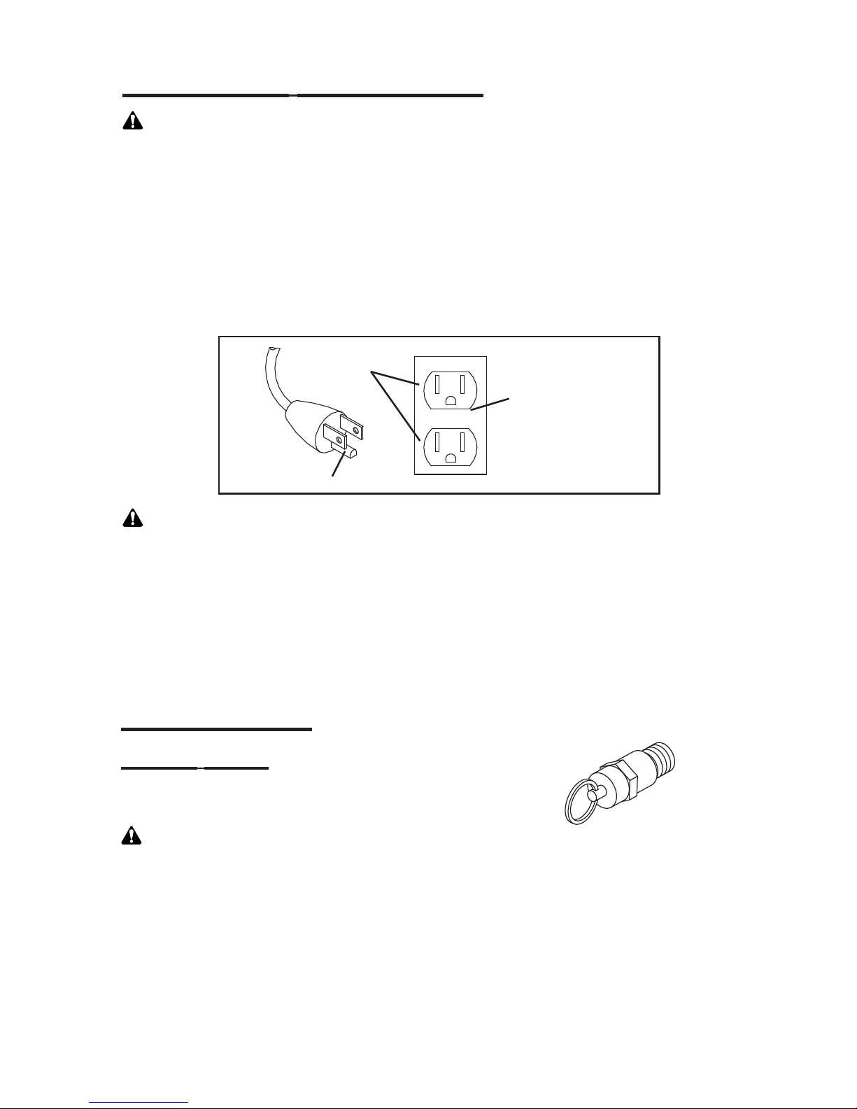
Grounding Instructions
DANGER: Improper grounding can result in electrical shock. In the event of a
short circuit, grounding reduces the risk of shock by providing an escape wire for
the electric current. The air compressor must be grounded. This compressor is
for use on a nominal 120 volt circuit and is equipped with a grounding wire and
appropriate grounding plug that looks like the plug illustrated. The plug must be
used with an outlet that has been installed and grounded in accordance with
all local codes and ordinances. Make sure that the compressor is connected
to an outlet having the same conguration as the plug. No adapter should be
used with this product. Inspect the plug and cord before each use. Do not use
compressor if there are signs of damage.
DANGER: Improper installation of the grounding plug can result in electrical
shock. If repair or replacement of the cord or plug is required, do not connect
the grounding wire to either at blade terminal. The wire with the green (with or
without yellow stripes) insulation is the grounding wire and must be connected to
the grounding pin. Check with a qualied electrician if the grounding instructions
are not completely understood, or if unsure unit is properly grounded. Do not
modify the plug that has been provided. If it does not t the available outlet, the
correct grounded outlet must be installed by a qualied electrician.
OPERATION
Safety Valve
The safety valve is designed to prevent pressure
in the storage tank from exceeding 140 PSIG.
WARNING: Do not tamper with or attempt to eliminate the safety valve.
4
GROUNDED
OUTLET BOX
GROUNDED
OUTLET
GROUNDING PIN
Page 7
5
Thermal Overload Protector
The compressor motor is equipped with a thermal overload protector. If the motor
should overheat, the overload protector will shut the motor off. If this occurs,
turn the on/off lever to the off position and allow motor to cool for approximately
5 minutes.
NOTE: Tank pressure must be below 100 PSIG for the compressor to start.
Restart the compressor by moving on/off lever to the on position. If compressor
fails to start, check for blown fuses; the compressor may require more time to
cool. If the overload protector shuts down the motor frequently, it could be due
to low voltage.Common signs of low voltage are:
1. Motor does not get up to power or speed.
2. Fuses or circuit breaker activate when starting compressor.
3. Lights dim or remain dim when compressor is started.
4. Other motor operated appliances fail to operate property.
5. Too many motor operated appliances on same circuit.
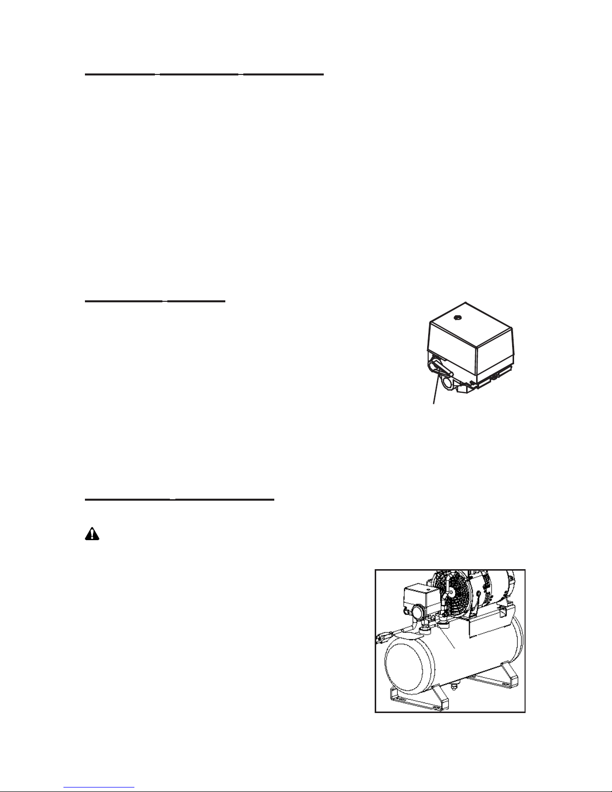
Pressure Switch
The compressor is operated by an on - auto/off lever on
the side of the pressure switch. By turning the lever to
the “AUTO” position the compressor will start and stop
automatically within the settings of the pressure switch. The
pressure switch is factory adjusted to start the compressor
when the tank pressure drops below 100 PSIG and to
stop when tank pressure reaches 122 PSIG. To stop the
compressor, turn the lever clockwise to the “OFF” position.
(DO NOT STOP THE COMPRESSOR BY REMOVING THE
ELECTRICAL PLUG.) The on/off lever operates a valve which relieves pressure
from the compressor. If the lever is left on when the electric power is interrupted,
the compressor may have difculty in starting under this pressure.
Operating Procedures
1. Make sure on/off lever is in the off position.
WARNING: Before using air tools or accessories, check manufacturer’s
maximum pressure rating. Maximum pressure rating must be above 122
PSIG.
2. Attach air hose and accessory to compressor.
(Remove orange pull plug rst.)
3. Turn on/off lever to the on position and allow tank
pressure to build.
4. When the motor stops, it has reached cutout
pressure and the unit is ready for use.
attach air hose
Lever
Page 8
NOTE: When using an accessory or air tool, pressure in the storage tank
decreases. When it reaches a certain low level (cut-in pressure) the motor will
automatically restart and raise the pressure in the storage tank.
5. To shut down compressor, simply move on/off lever to the off position.
6. Allow compressor to cool.
7. Drain storage tank (see Storage Tank in Maintenance Section).
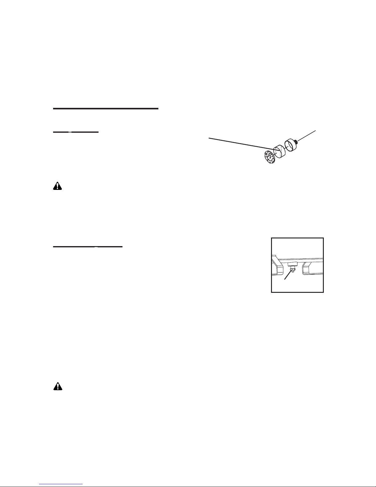
MAINTENANCE
Air Filter
Inspect air lter before each use. Clean lter
with soap and water as necessary. Squeeze
excess moisture from lter and allow to dry before
re-installing. If lter becomes clogged or damaged,
replace it.
WARNING: Never clean air lter with a ammable liquid or solvent.
Explosive vapors may accumulate in the air tank and cause an explosion,
resulting in serious injury or death.
CAUTION: Do not operate air compressor without air lter.
Storage Tank
The storage tank should be drained after each use or after every
four hours of operation to prevent condensation build-up and
corrosion inside the tanks. To drain tank, slowly and carefully
open drain tting, tip unit upright and allow water to drain out.
Always drain tank before storing compressor.
DO NOT over tighten drain valve when closing. The drain valve on this tank
seals primarily through the o-ring seal. Over tightening the valve can damage
the o-ring and may cause premature failure. To prevent damage, stop closing
the valve as soon as air can no longer be heard escaping from the valve, or
when nger tight.
NOTE: When draining tank, watch for debris (rust particles). If there appears
to be debris in water, contact your dealer for possible tank replacement. The
appearance of rust inside the tank will compromise its’ ability to hold pressure
and can cause bursting.
WARNING: Do not weld on the air tank of this compressor. Welding
on the air compressor tank can severely impair tank strength and cause
an extremely hazardous condition. Welding on the tank in any manner
will void the warranty. If warranty service or repairs are needed contact
your nearest authorized servicing dealer. If one does not exist contact
the factory. Unauthorized teardown of the unit will void the factory
warranty.
6
tank
drain
Page 9

7
REGLAS PARA UNA OPERACION SEGURA
PRECAUCION: Antes de operar el compressor de aire, lea este manual del
propietario y asegúrese de comprender la información aqui contenida.
1. El compresor debe ubicarse en una zona seca, timpia y bien ventilada.
2. Antes del uso, inspeccione la manguera, el tapón y elcable para
asegurarse de que estén en buenas condiciones. En caso contrario, no use
el compresor. Las unidades dañadas nunca deben operarse. Para la obtención
de piezas de reemplazo, consulte con su centro de servicio más próximo.
3. El ajuste de la válvula de alivio de seguridad ha sido jado en la fábrica.
No lo altere. Los ajustes de esta válvula peudan provocar lesiones
graves.
4. Esta unidad no requiere lubricación. Puesto que el compresor no requiere
ser aceitado, la aplicación de aceite a cualquier componente podría resultar
en el suministro de aire contaminado al equipo correspondiente.
5. El ujo de aire comprimido no debe dirigirse a ninguna persona porque puede
provocar lesiones graves. No permita que se acerquen los niños.
UTILICE PROTECTORES PARA LOS OJOS.
6. Todos los compresores de aire generan calor, aun bajo condiciones de
operacion normales. Para evitar quemaduras graves no toque el cabeza ni los
componentes del escape del compresor durante la operación o inmediatamente
después de ella.
7. Cuando la unidad no esté en uso, enrolle el cablealrededor del compresor
y guárdelo en un lugar seco. No maltrate el cordón.
8. ANTES DEL SERVICIO, LA LIMPIEZA 0 EL DESMONTAJE DE
CUALQUIER PIEZA, APAGUE LA UNIDAD Y ALIVIE LA PRESION.
9. ESTE SISTEMA PUEDE PRODUCIR HASTA 9,5 kg/cm2 (135 psi). PARA
EVITAR RUPTURAS DE COMPONENTES Y LESIONES CORPORALES, NO
OPERE LA UNIDAD CON ACCESORIOS (POR EJEMPLO, PISTOLAS DE
PULVERIZACION, MANGUERAS Y CONECTORES DE MANGUERAS) CUYA
PRESION NOMINAL DE TRABAJO SEA INFERIOR A 9,5 kg/cm2 (135 psi).
Si se requieren reparaciones o servicio de garantia, póngase en contacto con
el centro de servicio autorizado más cercano. Si no dispone de un centro,
póngase en contacto con la fábrica. Las reparaciones o el desmontaje de la
unidad sin autorización anularán la garantía de fábrica.
APLICACIONES
Este compresor es ideal como unidad neumática primaria o secundaria para
prácticamente cualquier tipo de operación. Especialmente indicado para
talleres, garajes y fábricas en donde el uso continuo exige gran abilidad.
Page 10

8
EL MANTENIMIENTO GENERAL Y SERVICIO
Lea y entienda la información de este maual del propletario del compresor que opera.
ESPECIFICACIONES
Voltaje.......................................................................................................... 115V, 60Hz
Requisitos del Fusible ............................................................................................ 10 A
Regulación de Valvulas de Seguridad..........................................140 PSIG (965.3KPa)
Desplazamiento de Aire.................................................................. 1.70 CFM (48 LPM)
Descarga de Aire ............... 0.90 CFM @ 100 PSI.............. (25.48 LPM @ 689.5 KPa)
Amps a Presión de Trabajo ................................................................................... 3.9 A
Control Automático .................Comienza @ 98 PSIG ................................(675.7 KPa)
..................................Para @ 122 PSIG .......................................(841.2 KPa)
Tamaño del Tanque ............................................................................................. 2 Gal.
Peso ................................................................................................................... 32 Ibs.
Cable conductor .....................................................................................6 pies (1.83 M)
PSI - Libras Por Pulgadas Cuadradas CFM - Pies Cúbicos Por Minuto
DISPOSICION DE LA UNIDAD UBICACION DEL COMPRESOR DE AIRE
Haga uso del compresor de aire en un área limpia, seca y bien ventilada. El ltro de
aire debe mantenerse libre de obstrucciones que pudieran reducir el ujo de aire que
recibe el compresor. El compresor de aire debe ubicarse por lo menos a 12” de paredes
y otras obstrucciones que puedan interferir con el ujo del aire.
1. Saque el compresor de aire de la caja de cartón y
colóquela a un lado.
2. Instale las 4 patas de caucho con los tornillos incluidos
en el kit de accesorios como se muestra.
3. Cierre la válvula de drenaje del tanque.
4. Quite el tapón de lengüeta anaranjado del puerto de
admisión en la cabeza del compresor e instale el ltro de
admisión que se proporciona en el kit de accesorios.
5. Quite 2 tornillos de cabeza e instale la manija con
los accesorios del kit.
6. Gire la palanca on/auto/off en el conmutador de
presión a la posición de apagado (OFF).
7. Sujete la manguera de aire al colector del
compresor.
8. Conecte el cable eléctrico a una salida puesta a
tierra o a otra extensión aprobada. (Vea la sección
Instrucciones para descarga a tierra.) Gire la
palanca on/auto/off en el conmutador de presión
a la posición de encendido (ON).
manguera
neumática
Page 11

9
CABLES DE CONEXION
Para evitar al motor disminución de tensión y pérdida de potencia, use una manguera
adicional en lugar de un extension electrica. Si hay necesidad de usar un extension
electrica, use únicamente un cable de conexión de 3 hilos equipado con un enchue de
tierra de 3 gajos y un tomacorriente de tres ranuras que acepte el enchufe del compresor.
Asegúrese de que el cable de conexión esté en buen estado.
NOTA: El tamaño del cable aurnenta conforme el calibre disminuye.
INSTRUCCIONES PARA LA CONEXION A TIERRA
PELIGRO: Una Conexión a tierra incorrecta puede dar como resultado un choque
electrico. En caso de un corto circuito, la conexión a tierra disminuye el riesgo de un
choque ya que provee un cable de escape para la corriente eléctrica.
El compresor de aire debe tener una conexión a tierra. El cable del compresor de
aire viene listo con un cable con conexión a tierre y un enchufe con conexión a tierra
apropiado. El enchufe debe ser usado con un tomacorriente que al ser instalado
haya seguido las leyes y ordenanzas locales para efectos de conexiones a tierra. El
tomacorriente debe tener la misma conguración del enchufe. No use un adaptador.
No le haga modicaciones al enchufe que se provee. Si no encaja bien en el
tomacorriente existente, un electricista profesional debe instalar el tomacorriente
correspondiente. Inspeccione el enchue y el cable cada vez que use la unidad.
No use el compresor si presenta señales de averías.
PELIGRO: Si la instalación del enchue conectado a tierra es hecha
incorrectamente, puede producirse un choque eléctrico. Si necesita reparar o
reemplazar el cable o el enchufe, no conecte el cable a tierra a ninguno de los
dos gajos planos del terminal. El alambre con el aislamiento verde (con o sin
rayas amarillas) es el alambre conectado a tierra. Consulte con un electrista
calicado si no comprende completamente las instrucciones que se dan aqui
para hacer la conexión a tierra, o si no está seguro de haber hecho la conexión
a tierra en forma apropiada.
TOMACORRIENTE
CONECTADO A
TIERRA ESTUCHE
TOMACORRIENTE
CONECTADO A
TIERRA
CLAVIJA
CONECTADA A TIERRA
MEDIDAS MINIMAS PARA LOS CABLES DE CONEXION
LONGITUD DEL CABLE 25 PIES 50 PIES 100 PIES 150 PIES
CALIBRE 12 12 10 8
Page 12

COMPRESSOR PARTS LIST
10
EXPLODED VIEW
AND PARTS LIST
Item
No.
Part No. Description Qty
17 647076 Fan Guard 1
18 603178 Capacitor Bracket 1
19 625434 Screw 8/16” x 3/8 Torx 2
20 603025 Capacitor 8mfd/450V 1
21 603167 Capacitor Cover 1
22 625449 Screw 8/32” x 3/8 Torx 2
23 633160 Strain Relief Bushing 1
24 660710 Filter Body 1
25 641034 Filter-Foam 1
26 660767 Filter-Body Cap 1
27 629081 Handle 1
28 625379 Screw-Handle 2
29 626014 Washer-Handle 2
Item
No.
Part No.
Component
Part
Description Qty
1 666459-S Conn. Rod Ass’y-Service 1
2* 625088 Eccentric Set Screw 1
3* 624396 Piston Cup 1
4 625180 Screw-Cup Retainer 1
5* 626397 Piston Cup Retainer 1
6* 670031 Cylinder Sleeve 1
7 610869-500 Head 1
8* 623143 O-Ring Head Gasket 1
9 625175 Screw-Head 4
10* 621647 Valve Backer 1
11* 617562 Valve Keeper Strip 2
12* 621485 Valve Flapper-Int. & Exh. 2
13 621632-540 Valve Plate 1
14* 625094 Screw-Valve Plate 2
15* 623071 O-ring-Valve Plate 1
16 638281 Fan-Black 1
Page 13

TANK PARTS LIST
11
46
50
45
37
41
43
42
35
36
33
34
47
48
30
49
31
44
38
39
32
40
39
Item
No.
Part No. Description Qty
30 602657 Pressure Switch 1
31 615779 Sleeve - Self Aligning 1
32 618149 Exhaust Tube 1
33 615826 Unloader Tube 1
34 624925 Fitting 1
35 617677 Drain Cock Assembly 1
36 624361 Elbow - Unloader Tube 1
37 624654 Bumper 1
38 624510 Insert-Unloader Tube 2
39 624511 Insert-Exhaust Tube 1
Item
No.
Part No. Description Qty
40 624517 Connector - Head 1
41 625206 Screw-Cprsr. Mounting 4
42 626563 Washer- Cprsr. Mounting 4
43 626509 Lock Washer-Cprsr. Mtng. 4
44 626766 Nut - Compression 1
45 625406 Screw - Bumper 4
46 633660 Cord 1
47 633957 Safety Valve 1
48 638262 Gauge - Pressure 1
49 638322 Check Valve Assembly 1
50 669470-540 Tank Assembly 1
Page 14

12
OPERACION
VALVULA DE SEGURIDAD
La válvula de seguridad ha sido diseñada para prevenir
que la presión en los tanques de almacenamiento exceda
á 140 PSIG.
PRECAUCION: No altere ni trate de eliminar la válvulade seguridad.
PROTECTOR TERMICO PARA SOBRECARGA
El motor del compresor está equipado con un protector térmico para sobrecarga.
Si el motor se llegara a recalentar, este protector apagará el motor. Si esto
ocurre, apague la unidad y deje que el motor se enfríe aproximadamente unos
5 minutos.
NOTA: La presión del tanque debe estar bajo 110 PSIG para que el compresor
arranque.
Encienda la unidad para volver a arrancar el compresor. Si elcompresor no
arranca, revise la unidad en busca de fusibles quemados; el compresor puede
necesitar más tiempo para enfriarse. Si el protector de sobrecarga apaga el
motor frecuentemente, podri’a ser que hay voltaje bajo.Indicaciones comunes
de un voltaje bajo son:
1. El motor no llega a su capacidad y velocidad.
2. Los fusibles y el cortacircuitos se activan cuando searranca el compresor.
3. Las luces bajan su intensidad al arrancar el compresor permanecen
amortiguadas.
4. Otros aparatos operados por el motor no funcionan en forma apropiada.
5. Hay demasiados aparatos operados por el motor en el mismo circuito.
FUNCIONAMIENTO DEL INTERRUPTOR DE PRESION
El compresor es operado por medio de una
palanca ON/AUTO-OFF, localizada en un
lado del interruptor de presion. Gire la
palanca a la posicion “ON-AUTO”, y el
compresor arrancara y parara automatica-
mente dentro del rango de presion del interruptor.
El interruptor esta ajustado de fabrica para arrancar
el compresor a presiones inferiores de 110 PSI, y para
cuando la presion alcanza 135 PSI en el tanque. Para
parar el compresor, gire la palanca a la posicion “OFF”. (NO PARE EL
COMPRESOR REMOVIENDO LA CLAVIJA DEL TOMACORRIENTE). La
palanca ON-OFF opera una valvula, la cual alivia la presion del compresor.
Si la palanca se deja en “ON” cuando la corriente electrica es interrumpida,
entoces el compresor podria tener dicultad para arrancar.
Page 15

13
PROCEDIMIENTO PARA EL FUNCIONAMIENTO
1. Asegúrese de que la unidad está apagada.
PRECAUCION: Antes de usar herramientas o accesorios neumáticos,
revise la capacidad de presión máxima del fabricante. Le capacidad de presión
máxima debe estar sobr e 135 PSIG.
2. Una la manguera neumática y el accesorio.
3. Ponga la palanca de conectar y desconectar
en posición on” y deje que la presión del tanque
aumente.
4. Cuando el motor se para, ha alcanzado presión
de desconexión y la unidad está lista para usarse.
5. Para apagar el compresor, simplemente mueva
la palanca de conectar y desconectar a la posición “off”.
6. Deje enfriar el compresor.
7. Drene los tanques de almacenamiento (veáse
Tanques de Almacenamiento en la Sección de Mantenimiento).
MANTENIMIENTO
FILTRO DE AIRE
Revise el ltro de aire antes de cada uso.
Limpie el ltro con agua y jabón según sea
necessario. Apriete el ltro para eliminar el
exceso de humedad y deje que se seque antes
de volverlo a instalar Si el ltro está obstruído o
dañado, reemplácelo.
ADVERTENCIA: No opere el compresor de aire sin ltro de aire.
PRECAUCION: Nunca limpie el ltro de aire con un liquido inamable o un
disolvente. Vapores explosivos podrían acumularse en los tanques de aire y
causar una explosión, dando como resultado lesiones serias o muerte.
manguera
neumática
Page 16

14
ADVERTENCIA: No suelde en los tanques de aire de estos compresores.
Soldar en los tanques de aire de estos compresores puede dañar
seriamente la fortaleza del tanque y causar una situación extremadamente
peligrosa. Una soldadura de cualquier tipo en los tanques puede ocasionar
la perdida de la garantia. Si algun servicio de garantia o cualquier reparo
es necesario comuniquese con su distribuidor más cercano. Si este no
existe, comuniquese con la fábrica. Cualquier desmontaje desautorizado
en la unidad cancelara la garantia de la fábrica.
TANQUES DE ALMACENAMIENTO
Los tanques de almacenamiento deben vaciarse
después de cada uso o después de cada cuatro
horas de operación para prevenir la creación de
condensación y corrosión dentro de los tanques.
Para vaciar los tanques, lentamente y con mucho
cuidado abra los accesorios de desague, incline la
unidad hacia el drenaje y deje que se desagüe.
NOTA: Cuando esté drenado los tanques, fjese si salen trozos de metal corrido,
se esto ocurre debe contactar a su distribuidor para posible reemplazo del
tanque.
tanques
desagüe
Page 17

15
ATTENTION: Veuillez lire attentivement ce manuel d’utilisation avant de vous
servir de ce compresseur d’air
1. Le compresseur doit être utilisé dans un endroit sec, propre et bien aéré.
2. Avant l’emploi, examiner le tuyau, la che et le l électrique pour repére tous
signes de déterioration. Ne pas utiliser l’appareil en cas de défaut de fonctionnement
ou de matériel. Addressez-vous au service entretien le plus proche pour obtenir des
pièces de rechange. Ne jamais utiliser un appareil défectueux.
3. Ne pas modier la pression de la soupape de sûreté: elle a été réglée en
usine. Tout autre réglage pourrait entráiner un risque de blessure grave.
4. Ce compresseur d’air ne nécessite aucune lubrication. Le graissage des pièces
risque de polluer l’air comprimé alimentant les accessoires pneumatiques.
5. L’air comprimé ne doit jamais être pointé sur une personne, car il peut entráiner des
blessures graves. Eloigner les enfants de l’endroit de travail. PORTER DES LUNETTES
DE PROTECTION.
6. Tous les compresseurs d’air produisent de la chaleur, même dans des conditions de
fonctionnement normales. An d’eviter tes brûlures, ne jamais toucher le compresseur
d’air pendant ou tout de suite après utilisation.
7. Quand il n’est pas utilisé, enrouler le l électrique autour du compresseur et stocker
dans un endroit sec. Faire attention à ne pas endommager le l électrique.
8. AVANT D’UTILISER, DE NETTOYER OU DE RETIRER TOUT ACCESSOIRE,
DEBRANCHER L’APPAREIL ET REDUIRE LA PRESSION.
9. CE SYSTEME PEUT PRODUIRE 9,5 kg/cm2 (135 psi). POUR EVITER TOUTE
RUPTURE POUVANT ENTRAINER DES BLESSURES, NE PAS UTILISER CETTE
POMPE AVEC DES ACCESSOIRES PREVUS POUR UNE PRESSION INFERIEURE
A 9,5kg/cm2 (135 psi) (Y COMPRIS MAIS NON LIMITE AUX PISTOLETS A PEINTURE,
TUYAUX ET RACCORDS DES TUYAUX).
Si des réparations ou un entretien en cours de garantie s’avèrent nécessaires,
addressez-vous au service entretien agréé le plus proche. S’il n’y en a pas, addressezvous à l’usine. Des réparations ou un démontage non permis
annuleront la garantie usine.
UTILISATION
Idéal comme source d’air primaire ou secondaire pour pratiquement toute opération.
Particulièrement pratique pour boutiques et garages ainsi que pour les usines où un
usage répété requiert un appareil de haute abilité.
PRECAUTIONS D’EMPLOI
Page 18

16
Lisez et comprenez l’information dans le manuel de ce propriétaire
avant d’opérer le compresseur.
CARACTERISTIOUES
Voltage..........................................................................................................115V, 60Hz
Fusibles...................................................................................................................10 A
Réglage de la soupape de Sûreté.............................................. 140 PSiG (965,3 KPa)
Volume d’air déplace ..................................................................... 1,70 CFM (48 LPM)
Débit d’air ........................... 0,90 CPM à 100 PSI............... (25.48 LPM à 689,5 KPa)
Ampéres quand l’appareil est sous pression .................................................. 3,9 AMP
Contrôle automatique .................... Démarre à 98 PSIG............................ (675,7 KPa)
......................................... S’arrête à 122 PSIG............................ (841,2 KPa)
Poids................................................................................................................. 32 livres
Contenance des réservoirs ..............................................................................2 gallons
Fil électrique ......................................................................................... 6 pieds (1.83m)
PSI - Livres par pouce carré CFM - Pieds cubes par minute
USAGE INSTALLATION
Emplacement du compresseur d’air
Faites fonctionner le compresseur d’air dans un endroit propre, sec et bien áeré. Le
ltre à air ne doit jamais être bouché, ce qui réduirait le débit d’air au compresseur. Le
compresseur d’air doit être placé à 4m (12 pieds) au moins de murs ou d’autres éléments
d’obstruction qui pourraient interférer avec le débit de l’air.
1. Retirer le compresseur d’air du carton et le placer sur
sa partie latérale.
2. Monter les 4 pieds en caoutchouc à l’aide des vis fournies
avec l’ensemble d’accessoires comme indiqué.
3. Fermer le robinet de vidange du réservoir.
4. Enlever 2 vis de tête et installer le levier de manœ
uvre à l’aide du matériel fourni avec l’ensemble
d’accessoires.
5. Activer/placer en mode automatique ou
désactiver le levier sur le pressostat en position
‘’OFF’’.
6. Relier le tuyau d’air au distributeur du compresseur.
7. Raccorder le câble d’alimentation dans une prise de
courant à contact de mise à la terre ou une rallonge
agréée. (Voir la partie des procédures de mise à l
a terre). Activer/placer en mode automatique ou
désactiver le levier sur le pressostat en position ‘’ON’’.
ENTRETIEN GÉNÉRAL ET SERVICE
Relier le tuyau d’air
Page 19

17
Rallonge Électrique
Pour éviter des chutes de voltage et des pertes de puissance au moteur,
utilisez des tuyaux supplémentaires au lieu d’une rallonge électrique.
Si une rallonge doit être utilisée, n’utilisez qu’une rallonge électrique
à trois ls avec une che à troisbroches (prise de terre) et une prise à
trois trous pour recevoir la che qui se trouve sur le compresseur d’air.
Assurez-vous que la rallonge est en bon état.
REMARQUE: La grosseur du l augmente lorsque ie chiffre du cali-
bre diminue.
Instructions de mise à la terre
DANGER: Une mauvaise mise à la terre peut causer des électrocutions.
En cas de court-circuit, la mise à la terre réduit le risque d’électrocution
en permettant au courrant de s’échapper. Le compresseur d’air doit être
mis à la terre. Le l électrique du compresseur d’air est équipé d’un l
de terre et d’une che de terre appropries. La che doit être utilisée
avec une prise installée et mise à la terre selon les règlements et les
ordonnances locales. La prise doit avoir le même conguration que la che.
Ne pas utiliser d’adaptateur.Ne modiez pas la che qui vous est fournie. Si
celle-ci ne s’adapte pas à la prise disponible, il faut faire installer la prise
correcte par un électricien. Inspectez la che et ie t électrique avant
chaque utilisation. N’utilisez pas le compresseur d’air si ces élements
sont endommagés.
DANGER!: Une mauvais installation de la che de terre peut causer
une électrocution. S’il faut réparer ou changer le l électrique, ne
raccordez pas le l de terre à n’importe quelle che plate de terre.
PRISE AVEC
PRISE DE
TERRE BOITE
PRISE AVEC
PRISE DE
TERRE
FICHE DE TERRE
CALIBRE MINIMUM DES RALLONGES ELECTRIQUES
DE RALLONGE 25 PIEDS 50 PIEDS 100 PIEDS 150 PIEDS
CALIBRE 12 12 10 8
Page 20

18
Le l recouvert d’un isolant vert (avec ou sans raies jaunes) est le
l de terre. Faites vérier l’installation par un électricien qualié si
vouscomprenez pas entiérement les instructions concernant la mise à
la terre, ou si vous n’êtes pas sûr que l’appareil soit correctement mis
à la terre.
FONCTIONNEMENT
Soupape de sûreté
La soupape de sûreté est concue pour
que la pression qui se trouve dans les
réservoirs d’accumulation n’excède pas
165 PSIG.
ATTENTION!: N’essayez pas de modier ou de supprimer la soupape
de sûreté.
Protecteur de surchauffe
Le moteur du compresseur est équipé d’un protecteur de surchauffe.
Si le moteur vient à surchauffer, le protecteur de surchauffe arrêtera le
moteur. Si cela arrive, mettez le levier marche/arrêt sur la position arrêt
et laissez le moteur se refroidir pendant environ cinq minutes.
REMARQUE: La pression du réservoir doit être inférieure à 110
PSIG pour que le compresseur puisse redémarrer. Redémarrez le
compresseur en mettant le levier marche/arrêt à la position marche.
Si le compresseur ne démarre pas, vériez les fusibles pour voir s’ils
n’ont pas sauté; iI se peut que le compresseur ait besoin de plus de
temps pour refroidir. Si le protecteur de surchauffe arrête fréquemment
le moteur, cela peut venir d’un faible voltage. Les signes habituels d’un
faible voltage sont les suivants:
1. Le motteur manque de puissance ou ne peut atteindre la vitesse
normale.
2. Les fusibles ou le disjoncteur sautent lorsque le compresseur
démarre.
3. Les lumières des lampes baissent ou restent faibles lorsque le
compresseur démarre.
4. D’autres appareils à moteur ne marchent pas correctement.
5. Trop d’appareils à moteur sont sur le même circuit électrique.
Page 21

19
COMPRESSEUR DE PRESSION
Le compresseur fonctionne par un leveir en action
auto/fermé au-dessus de la côté de commutateur
de pression. En tournant le levier à la position
horizontal e le compresseur démarrera et cessera
automatiquement à l’interieur de la position
de commutateur de pression. Le commutateur
de pression est fait dans la fabrique et ajusté
pour mettre en marche le compresseur quand
la pression du réservoir tombe au-dessous de
110 PSIG et de cesser quand la pression de
réservoir atteind jusqu’a 135 PSIG. Pour fermer le compresseur tourner
le levier dans sens des aguilles d’une montre á la position verticale.
(NE FERMER JAMAIS LE COMPRESSEUR PAR ENLEVEMENT LE
TAMPON ELECTRIQUE). Le levier de en action/ferme fonctionne la
soupape qui soulage la pression de compresseur. Si le levier est laissé
en action quand la puissance électrique est interrompue, le compresseur
peut avoir la difculté de démarrer avec cette pression.
MODE D’EMPLOI
1. Assurez-vous que le levier marche/arret se trouve sur la position
position d’arrêt.
ATTENTION!: Avant de vous servir d’outils ou d’accessoires à air
comprimé, vériez le taux maximum de pression recommandé par le
fabricant. Ce taux doit être supérieur à 122 PSIG.
2. Attachez le tuyau el l’accessoire.
3. Mettez le levier sur la position marche et laissez la pression monter
dans le réservoir.
4. Quand le moteur s’arrête, il a atteint son niveau de pression d’arrét
et l’appareil est prét à fonctionner.
REMARQUE: Quand vous utilisez un accessoire ou un outil à air
comprimé, la pression dans les réservoirs d’accumulation décroít. Quand
celle-ci atteint un certain niveau minimum (perte de pression) le moteur
redémarrera aussitôt automatiquement et
fera monter la pression dans les réservoirs.
5. Pour arrêter le compresseur, mettez le
levier marche/arrêt sur la position arrêt.
6. Laissez la compresseur se refroidir.
7. Vindangez les réservoirs d’accumulation
(voir réservoirs d’accumulation à la section
entretien).
Page 22

20
ENTRETIEN
Filtre à air
Vériez le ltre à air avant chaque utilisation de l’appareil. Nettoyez le
ltre avec du savon et de l’eau si nécessaire.
Éliminez l’excès d’humidité du ltre et laissez-le
sécher avant de le remettre en place.Si le ltre est
bouché ou endommagé, remplacez-le.
ATTENTION!: Ne jamais nettoyer le ltre à air avec un liquide ou
un dissolvant inammable. Des gaz explosibles peuvent s’accumuler
dans les réservoirs et provoquer une explosion pouvant causer de très
graves blessures ou même la mort.
ATTENTION!: Ne faites pas marcher le compresseur sans ltre à
air.
Réservoirs d’accumulation
Les réservoirs d’accumulation doivent être
purgés après chaque utilisation ou toutes les
quatre heures de marche pour empêcher une
accumulation de condensation et la corrosion
de l’intérieur des réservoirs. Pour purger les
réservoirs, ouvrez lentement et soigneusement
les raccords de purge penchez l’appareil du côté
des raccords et laissez l’eau sortir.
REMARQUE: Quand vous purgez les réservoirs, regardez s’il se trouve
des débris (particules de rouille). Si oui, contactez votre concessionnaire
pour un éventuel remplacement des réservoirs.
ATTENTION!: Ne faites pas de soudures sur les réservoirs
de ces compresseurs. Des soudures sur les réservoirs de ces
compresseurs à air pourraient sérieusement affaiblir la résistance
des réservoirs et créer des conditions trés dangereuses. N’importe
quelle soudure sur un réservoir annulera la garantie. Si des travaux
sous garantie ou des réparations sont nécessaires addressez-vous
à un fournisseur/réparateur autorisé. S’il n’y en a pasprès de chez
vous contactez l’usine. Le démontage nonautorisé de l’appareil
annulera la garantie.
tank
drain
Page 23

21
ELECTRIC COMPRESSOR TROUBLESHOOTING
The following guide has been compiled to assist the consumer in identifying problems
that may be encountered with electric compressors. Please inspect for possible
causes and contact an authorized service center when necessary.
SYMPTOM POSSIBLE CAUSE CORRECTIVE ACTION
Motor Won’t Start No Power to Compressor
Switch Lever in “Off” Position
Faulty Start Relay
Faulty Start Capacitor
Check Circuit Breaker or
Fuse.
Move Switch Lever to On
Position.
Compressor Won’t
Restart
Check Valve Leaks
Low Voltage to compressor
Pressure Switch Hanging Up
Inspect Check ValveContact Service Center.
Connect Unit to Sufcient
Voltage Source.
Inspect Pressure SwitchContact Service Center.
Low Air Output Leak At Fitting(s)
Broken Valve Flapper
Debris in Valves
Faulty Head Gasket
Faulty Valve Plate Gasket
Worn Piston Cup
Inspect Fittings-If Loose or
Damaged Contact Service
Center.
Compressor Won’t
Shut Off
Leak At Fitting(s)
Broken Valve Flapper
Debris in Valves
Faulty Head Gasket
Faulty Valve Plate Gasket
Worn Piston Cup
Relief Valve Leaking
Inspect Fittings-If Loose or
Damaged Contact Service
Center.
Water in Air Lines or
Tools
Tank Not Drained Regularly Drain Air from Tank(s)
through Drain Valves.
Ensure Air Lines are Free
of Moisture.
Low Pressure to Tools Damaged Gauge on Regulator
Regulator Not Adjusted Properly
Faulty Regulator
Inspect Gauge-Contact
Service Center.
Adjust Regulator to
Required Pressure.
Inspect Regulator-Contact
Service Center.
These procedures require special xtures, tools or asssembly techniques
available only through a Service Center. For service, contact the dealer from whom
you purchased the compressor. To order parts, visit our website, www.thomasairpac.
com, or call our Customer Service Center at 1-800-848-7735.
ATTENTION: The automatic pressure switch prevents this
unit from running if the tank pressure exceeds 100PSI. If the
compressor will not start, drain the pressure from the tank.
Page 24

Thomas Products Division of
Gardner Denver Thomas, Inc.
C/O Customer Service
3524 Washington Avenue
Sheboygan, Wisconsin 53081
Phone: (800) 558-7721
Fax: (920) 451-6307
www.thomasairpac.com
Limited Warranty
The Gardner Denver Thomas, Inc. Compressor is warranted to you, the original
purchaser, for a period of one year from date of original purchase to be free from
defects in material and workmanship. If during the specied warranty period you
believe the purchased product or any part thereof has such a defect, you must return
the product or part during such period, with proof of purchase and at your cost, to the
nearest authorized service center (consult the list of service centers enclosed with the
product) for repair, or replacement of the defective part. If you do not know the location
of the nearest service center, contact Gardner Denver Thomas, Inc. at the address
below for instructions. If the product or part is found to have been defective in material
or workmanship, it will be repaired or replaced (as deemed necessary by the repair
center), free of charge, and returned to the purchaser at the purchaser’s cost. If the
repair work must be done at the Gardner Denver Thomas, Inc. factory, transportation
costs of the product or part, to and from the factory, must be paid by the purchaser.
The warranty shall not apply to any compressor, which in Thomas’ judgement has
been subject to misuse, negligence or accident, or which has been operated from an
inadequate power supply. All wearing and consumable parts are excluded under the
terms of this warranty. This warranty shall not apply to compressors that require oil for
operation, which have been operated with oil levels below that specied by Gardner
Denver Thomas, Inc.
THE MANUFACTURER LIMITS THE DURATION OF THE IMPLIED WARRANTY OF
MERCHANTABILITY TO THE LIMITED WARRANTY PERIOD SET FORTH ABOVE,
AND OTHERWISE DISCLAIMS ALL IMPLIED WARRANTIES WITH RESPECT TO
THE PRODUCT AND IT’S PARTS INCLUDING, WITHOUT LIMITATION, THE IMPLIED
WARRANTY OF FITNESS FOR A PARTICULAR PURPOSE.
Thomas’ total liability for any and all claims, damages, losses and injuries arising out of
or relating to any breach of warranty shall not exceed the purchase price of the product.
IN NO EVENT WHETHER IN CONTRACT, OR TORT, OR OTHERWISE SHALL
THOMAS BE LIABLE FOR LIQUIDATED, INDIRECT, EXEMPLARY, INCIDENTAL,
SPECIAL OR CONSEQUENTIAL DAMAGES, EXPENSES OR COSTS, INCLUDING
BUT NOT LIMITED TO: (1) LOSS OF PROFITS, BUSINESS, OR GOODWILL; (2)
LOSS OF USE OF EQUIPMENT OR FACILITIES; OR (3) LOSS RESULTING FROM
UNUSABLE MACHINERY OR FACILITY DOWNTIME, HOWSOEVER CAUSED AND
EVEN IF THE POTENTIAL FOR SUCH DAMAGES WAS DISCLOSED AND/OR
KNOWN.
The remedy provided in this Limited Warranty for defective product is purchaser’s
sole and exclusive remedy, subject to your state law. Further, this Warranty gives you
specic legal rights, and you may also have other rights, which may vary, from state
to state.
If you believe warranty service is needed, contact your nearest authorized service
center. If one does not exist in your area, please contact the manufacturer:
22
 Loading...