

Thomas T175, 1700 Repair Manual
Publication No. 49012
REPAIR MANUAL
T175/1700
THOMAS

THOMAS EQUIPMENT LIABILITY WARRANTY
THE WARRANTY IS THE ONLY OBLIGATION OF THOMAS OR A THOMAS DEALER
TO THE PURCHASER OR ANYONE ELSE CONCERNING A PRODUCT, ITS SERVICE,
ITS USE OR PERFORMANCE OR ITS LOSS OF USE OR FAILURE TO PERFORM.
NEITHER THOMAS NOR A THOMAS DEALER HAVE MADE AND NEITHER WILL
MAKE ANY OTHER EXPRESSED OR IMPLIED REPRESENTATION, WARRANTY OR
AGREEMENT CONCERNING A PRODUCT. NEITHER THOMAS NOR A THOMAS
DEALER HAVE MADE OR WILL MAKE ANY REPRESENTATION, WARRANTY OR
AGREEMENT CONCERNING A PRODUCTS MERCHANTABILITY OR OTHER
QUALITY, ITS SUITABILITY FOR PURCHASER’S PURPOSE (EVEN IF A PURCHASER
HAS INFORMED THOMAS OR A THOMAS DEALER OF THAT PURPOSE), ITS
DURABILITY, PERFORMANCE OR OTHER CONDITION.
EVEN IF THOMAS OR A THOMAS DEALER WAS ADVISE OF THE POSSIBILITY OF
SUCH LOSS, NEITHER THOMAS NOR A THOMAS DEALER WILL BE LIABLE TO
PURCHASER OR ANYONE ELSE FOR ANY INDIRECT, INCIDENTAL
CONSEQUENTIAL, PUNITIVE, ECONOMIC, COMMERCIAL, OR SPECIAL LOSS
WHICH IS IN ANY WAY ASSOCIATED WITH A PRODUCT. THIS INCLUDES ANY LOSS
OF USE OR NON-PERFORMANCE OF A PRODUCT, ANY REPLACEMENT RENTAL OR
ACQUISITION COST, ANY LOSS OF REVENUE OR PROFITS, ANY FAILURE TO
REALIZE EXPECTED SAVINGS, ANY INTEREST COSTS, ANY IMPAIRMENT OF OTHER
GOODS, ANY INCONVENIENCE OR ANY LIABILITY OF PURCHASER TO ANY OTHER
PERSON.
PURCHASER MAY NOT ATTEMPT TO ENLARGE ITS RIGHTS UNDER THE
WARRANTY BY MAKING A CLAIM FOR INDEMNITY, FOR BREACH OF CONTRACT,
FOR BREACH OF COLLATERAL WARRANTY, FOR A TORT (INCLUDING
NEGLIGENCE, MISREPRESENTATION OR STRICT LIABILITY) OR BY CLAIMING ANY
OTHER CAUSE OF ACTION.
THE WARRANTY IS A CONDITION OF SALE OF THE PRODUCT TO PURCHASER
AND WILL THEREFORE APPLY EVEN IF PURCHASER ALLEGES THAT THERE IS A
TOTAL FAILURE OF THE PRODUCT.
N.B. Read and practice your Thomas operating and servicing instructions. Failure to do this may
void your warranty.
Publication Number 49012
2
FOREWORD
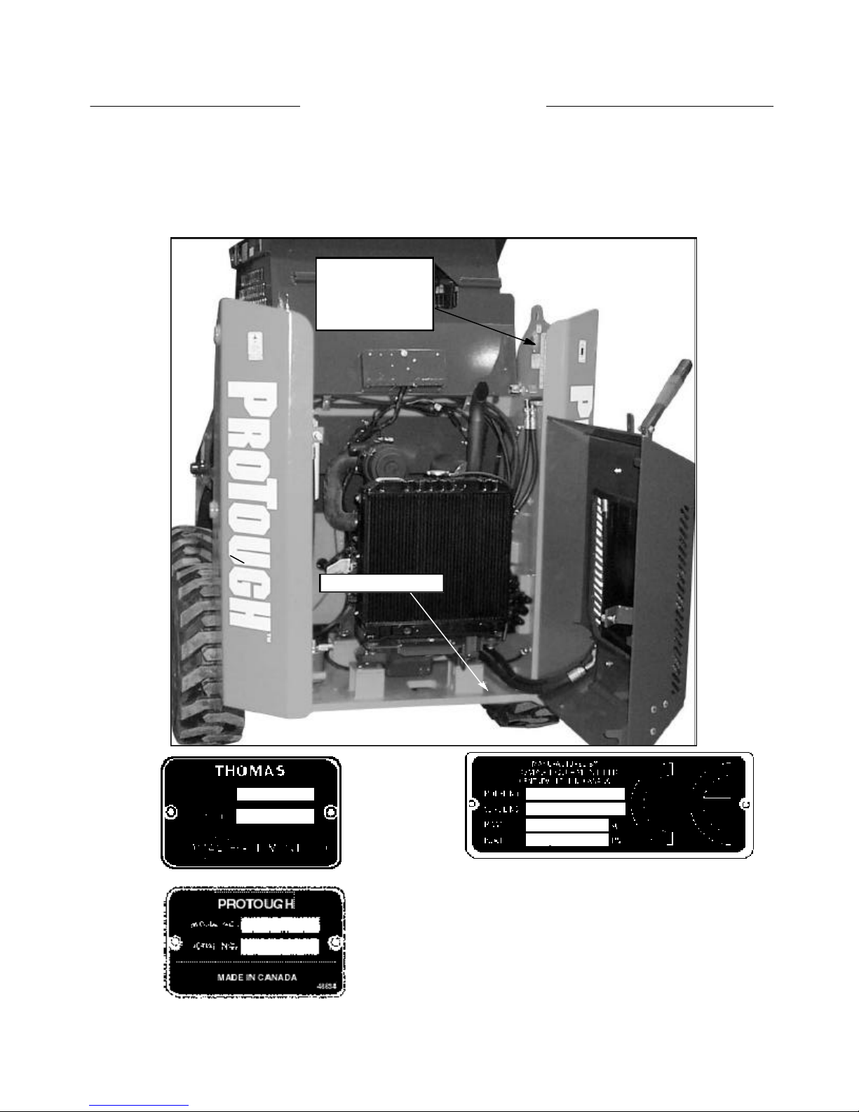
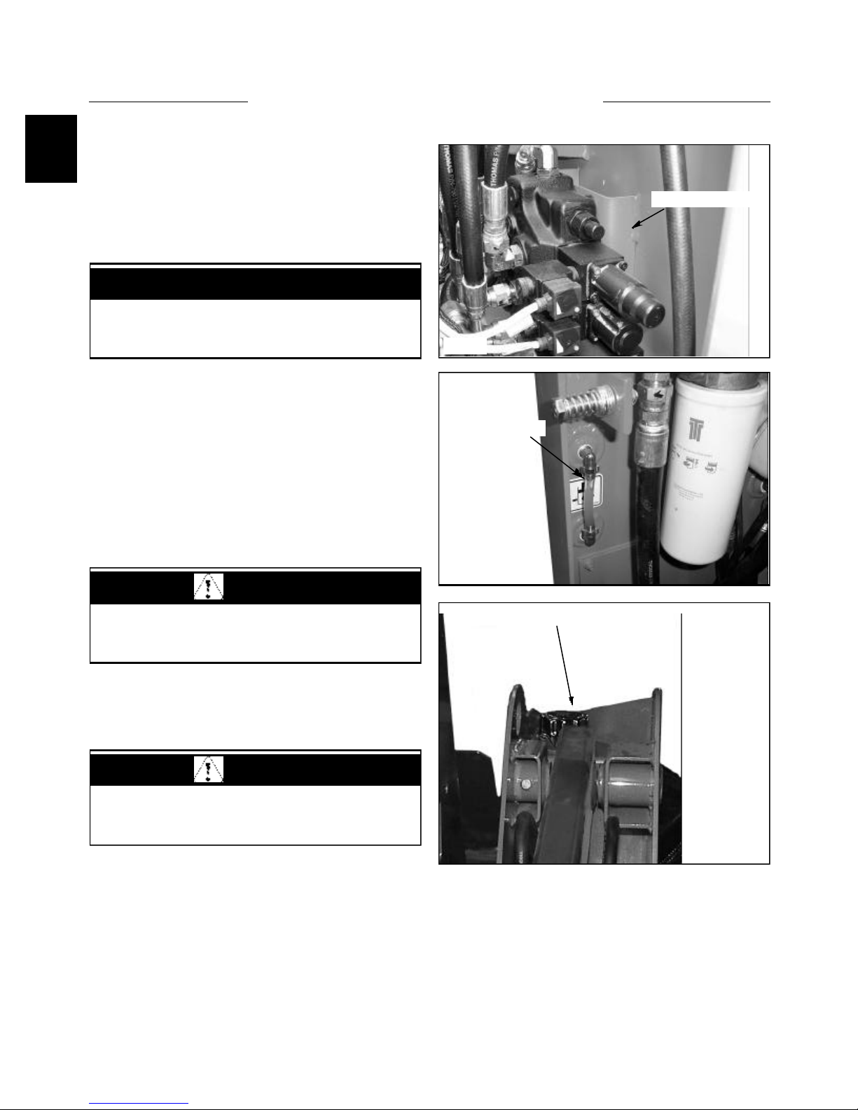
It is important when ordering replacement parts or making a service inquiry to provide both the model number
and serial number of your Thomas loader. The serial number plate is located at the rear of the machine on the
right hand side fuel tank. In the event that the serial number plate is missing, the model number and serial
number are both stamped into the main frame inside the rear door, next to the hydraulic control valve.
S / N Tag location.
Tag is found on
opposite side on
some models
C3313
S / N Stamp location
3
SAFETY PRECAUTIONS
Practically all Service work involves the need to drive the
loader. The Owner’s / Operator’s Manual, supplied with
each loader, contains safety precautions relating to
driving, operating and servicing that loader. These
precautions are as applicable to the service technicians as
they are to the operator and should be read, understood
and practiced by all personnel.
Prior to undertaking any maintenance or repair operations,
make the neccessary safety precautions to prevent
possible personal injury to yourself, or to bystanders.
PERSONAL CONSIDERATIONS
* CLOTHING
The wrong clothing or carelessness in dress can
cause accidents. Check to see that you are
suitably clothed. Some jobs require special
protective equipment.
* SKIN PROTECTION
Avoid long term contact with used motor oil.
Follow work practices that minimize the amount
of skin exposed and length of time used oil stays
on your skin.
* EYEPROTECTION
Injury can be avoided by wearing eye protection
when engaged in chiseling, grinding, welding,
painting and any other task that involves airborne
matter.
falling objects.
* SPECIALCLOTHING
For certain work it may be necessary to wear
flame or acid resistant clothing.
EQUIPMENT CONSIDERATIONS
CAUTION
Avoid injury through incorrect handling of
components. Make sure your are capable of lifting
the object. If in doubt, get help.
* MACHINE GUARDS
Before using any machine, check to ensure that
the machine guards are in position and
serviceable. These guards not only prevent parts
of the body or clothing coming in contact with
the moving parts of the machine but also ward
off objects that might fly off the machine and
cause injury.
* LIFTING APPLIANCES
Always ensure that lifting equipment, such as
chains, slings, lifting brackets, hooks and eyes
are thoroughly checked before use. If in doubt,
select stronger equipment. Never stand under a
suspended load or raised implement.
* BREATHING PROTECTION
Fumes, dust and paint spray are unpleasant and
harmful. These can be avoided by wearing
respiratory protection.
* HEARINGPROTECTION
Loud noise may damage your hearing and the
longer the exposure the greater the risk of
hearing damage. Always wear hearing protection
when working around loud machinery.
* HAND PROTECTION
It is advisable to use a protective cream before
work to prevent irritation and skin
contamination. After work, clean your hands
with soap and water. Solvents such as white
spirits, paraffin, etc. may harm the skin.
* FOOTPROTECTION
Substantial or protective footwear with
reinforced toecaps will protect the feet from
* COMPRESSED AIR
The pressure from a compressed air line is often
as high as 100 PSI (6.9 Bar). Any misuse may
cause injury.
Never use compressed air to blow dust, filing
dirt, etc. away from your work area unless the
correct type of nozzle is fitted.
Compressed air is not a cleaning agent. It will
only move dust etc. from one place to another.
Look around before using an air hose as
bystanders may get grit into their eyes, ears and
skin.
4

SAFETY PRECAUTIONS
* HAND TOOLS
Many cuts, abrasions and injuries are caused by
defective tools. Never use the wrong tool for the
job as this leads either to injury or to a poor job.
Never Use:
A hammer with a loose or split handle.
Spanners or wrenches with spread or worn
jaws.
Wrenches or files as hammers, drills, clevis
pins or bolts as punches.
For removing or replacing hardened pins use a
copper or brass drift.
For dismantling, overhaul and assembly of major
and sub-components always use the Special
Service Tools recommended. These will reduce
the work effort, labor time and the repair cost.
Always keep tools clean and in good working
order.
* ELECTRICITY
Electricity has become so familiar in day to day
usage that it’s potentially dangerous properties
are often overlooked. Misuse of electrical
equipment can endanger life.
Before using any electrical equipment,
particularly portable appliances, make a visual
check to ensure that the cable is not worn or
frayed and that the plugs, sockets etc.are intact.
Make sure you know where the nearest isolating
switch for your equipment is located.
GENERAL CONSIDERATIONS
* SOLVENTS
Use only cleaning fluids and solvents that are
known to be safe. Certain types of fluids can
cause damage to components such as seals, etc.
and can cause skin irritation. Solvents should be
checked that they are suitable not only for the
cleaning of components and individual parts but
also that they do not affect the personal safety of
the user.
* HOUSEKEEPING
Many injuries result from tripping or slipping
over, or on, objects or materials left lying around
by a careless worker.
Prevent these accidents from occurring. If you
notice a hazard, don’t ignore it, remove it.
A clean hazard free place of work improves the
surroundings and daily environment for
everybody.
* FIRE
Fire has no respect for persons or property. The
destruction that a fire can cause is not always
fully realized. Everyone must be constantly on
guard.
- Extinguish matches, cigars, cigarettes etc.
before throwing them away.
- Work cleanly, disposing of waste material into
proper containers.
- Locate all the fire extinguishers and ensure all
personnel know how to operate them.
- Do not panic, warn those near and sound the
alarm.
- Do not allow or use an open flame near the
loader fuel tank, battery or component parts.
* FIRST AID
In the type of work that mechanics are engaged
in, things such as dirt, grease, fine dust etc. all
settle upon the skin and clothing. If a cut,
abrasion or burn is disregarded it may be found
that a septic condition has formed in a short time.
What appears at first to be trivial could become
painful and injurious. It only takes a few minutes
to have a fresh cut dressed but it will take longer
if you neglect it.
* CLEANLINESS
Cleanliness of the loader hydraulic system is
essential for optimum performance. When
carrying out service and repairs, plug all hose
ends and components connections to prevent dirt
entry.
Clean the exterior of all components before
carrying out any form of repair. Dirt and abrasive
dust can reduce the efficiency and working life
of a component and lead to costly replacement.
Use of a high pressure washer or steam cleaner is
5
recommended.

SAFETY PRECAUTIONS
OPERATIONAL CONSIDERATIONS
* Stop the engine, if at all possible, before
performing any service.
* Place a warning sign on loaders which, due to
service or overhaul, would be dangerous to start.
Disconnect the battery leads if leaving such a
unit unattended.
* Do not attempt to start the engine while standing
beside the loader or attempt to bypass the safety
starting system.
* Avoid prolonged running of the engine in a
closed building or in an area with inadequate
ventilation as exhaust fumes are highly toxic.
* Always turn the radiator cap to the first stop to
allow pressure in the system to dissipate when
the coolant is hot.
* Never work beneath a loader which is on soft
ground. Always take the unit to an area which
has a hard working surface, preferably concrete.
* If it is found necessary to raise the loader for
ease of maintenance, make sure that safe and
stable supports are installed beneath the main
frame before commencing work.
* Use footsteps or working platforms when
servicing those areas of the loader that are not
within easy reach.
* Before loosening any hoses or tubes, switch off
the engine, remove all pressure in the lines by
operating the foot pedals several times. This will
remove the danger of personal injury by oil
pressure.
* If high lift attachments are installed on a loader,
beware of overhead power and telephone lines
when travelling. Drop attachment near to ground
level to increase stability and minimize risks.
* Do not park or attempt to service a loader on an
incline. If unavoidable, take extra care and block
the wheels.
* Escaping hydraulic / diesel fluid under pressure
can penetrate the skin causing serious injury. Do
not use your hand to check for leaks. Use a piece
of cardboard or paper to search for leaks. Stop
the engine and relieve pressure before connecting
or disconnecting lines. Tighten all connections
before starting the engine or pressurizing the
lines. If any fluid is injected into the skin, obtain
medical attention immediately.
* Prior to removing wheels and tires from a loader,
check to determine whether additional ballast
(liquid or weight) has been added. Seek
assistance and use suitable equipment to support
the weight of the wheel assembly.
* When inflating tires beware of over inflation;
constantly check the pressure. Over inflation can
cause tires to burst and result in personal injury.
* Safety precautions are very seldom the figment
of someone’s imagination. They are the result of
sad experience where most likely someone has
paid dearly through personal injury.
* Heed these precautions and you will protect
yourself accordingly. Disregard them and you
will duplicate the sad experiences of others.
* Prior to pressure testing, make sure all the hoses
and connectors on both the loader and on the test
machine are in good condition and tightly sealed.
Pressure readings must be taken with the gauges
specified. The correct procedure should be
rigidly observed to prevent damage to the system
or the equipment and to eliminate the possibility
of personal injury.
* Always lower equipment to the ground when
leaving the loader.
6

SAFETY PRECAUTIONS
SERVICE TECHNIQUES
A. SERVICE SAFETY
Appropriate service methods and proper repair
procedures are essential for the safe, reliable
operation of all motor vehicles as well as the
personal safety of the individual doing the work. This
shop manual provides general directions for
accomplishing service and repair work with
tested effective techniques. Following them will help
assure reliability.There are numerous variations in
procedures, techniques, tools and parts for servicing
vehicles as well as in the skill of the individual doing the
work. This manual cannot possibly anticipate all such
variations and provide advice or cautions as to each.
Accordingly, anyone who departs from the instructions
provided in this manual must first establish that he or she
compromises neither his personal safety nor the vehicle
integrity by his choice of methods, tools or parts.
B. SERVICE TECHNIQUES
Clean the exterior of all components before carrying out
any form of repair. Dirt and abrasive dust can reduce the
efficient working life of a component and lead to costly
replacement.
Use cleaning fluids which are known to be safe. Certain
types of fluid can cause damage to O- rings and cause
skin irritation. Solvents should be checked that they are
suitable for the cleaning of components and also that they
do not risk the personal safety of the user.
Time spent on the preparation and cleanliness of working
surfaces will pay dividends in making the job easier and
safer and will result in overhauled components being
more reliable and efficient in operation.
When installing a new hose, loosely connect each end and
make sure the hose takes up the designed position before
tightening the connection. Clamps should be tightened
sufficiently to hold the hose without crushing and to
prevent chafing.
The hoses are the arteries of the unit. Be sure they are in
good condition when carrying out repairs or maintenance.
Otherwise the machines output and productivity may be
affected.
After hose replacement to a moving component, check
that the hose does not foul by moving the component
through the complete range of travel.
Hose connections which are damaged, dented , crushed or
leaking, restrict oil flow and the productivity of the
components being served. Connectors which show signs
of movement from the original swaged position have
failed and will ultimately separate completely.
A hose with a chafed outer cover will allow water entry.
Concealed corrosion of the wire reinforcement will
subsequently occur along the hose length with resultant
hose failure.
Ballooning of the hose indicates an internal leakage due
to structural failure. This condition rapidly deteriorates
and total hose failure soon occurs.
Kinked, crushed, stretched or deformed hoses generally
suffer internal structural damage which results in oil
restriction, a reduction in the speed of operation and
ultimate hose failure.
Free moving, unsupported hoses must never be allowed to
touch each other or related working surfaces. This causes
chafing which reduces hose life.
Replace O rings, seals or gaskets whenever they are
disturbed. Never mix new and old seals and O rings,
regardless of condition. Always lubricate new seals and O
rings with hydraulic oil before installation.
When replacing component parts use the correct tool for
the job.
C. HOSES AND TUBES
Always replace hoses and tubes if the end connections are
damaged. Be sure any hose installed is not kinked or
twisted.
D. PRESSURE TESTING
Prior to pressure testing, be sure all hoses are in good
condition and all connections tight. Pressure readings
must be taken with gauges of specified pressure readings.
The correct procedure should be rigidly observed to
prevent damage to the system or the equipment and to
eliminate the possibility of personal injury.
7
SAFETY PRECAUTIONS
E. BEARINGS
Bearings which are considered suitable for further service
should be cleaned in a suitable solvent and immersed in
clean lubricating oil until required.
Installation of a bearing can be classified into two (2)
ways:
press fit on rotating parts such as shafts and gears,
push fit into static locations such as reduction gear
houses.
Where possible, always install the bearing onto the
rotating components first. Use the correct tools or a press
to install a bearing or bushing. In the absence of the
correct tools or press, heat the bearing and / or casing in
hot oil to assist the installation of the bearing.
When bearings or bushings are removed, always carefully
check that the bearing is free from discoloration and signs
of overheating. Also check for mechanical damage such
as excessive clearance, nicks and scuffing. If in doubt,
replace the bearings or bushings.
Bearings should never be removed unless absolutely
necessary. Always use the recommended puller to reduce
the risk of bearing or related component failure.
These bearings and bushings are subjected, in normal
operation, to high working loads and adverse conditions.
Be sure during normal routine servicing, maintenance or
repair that bearings are given the right attention and are
installed with care.
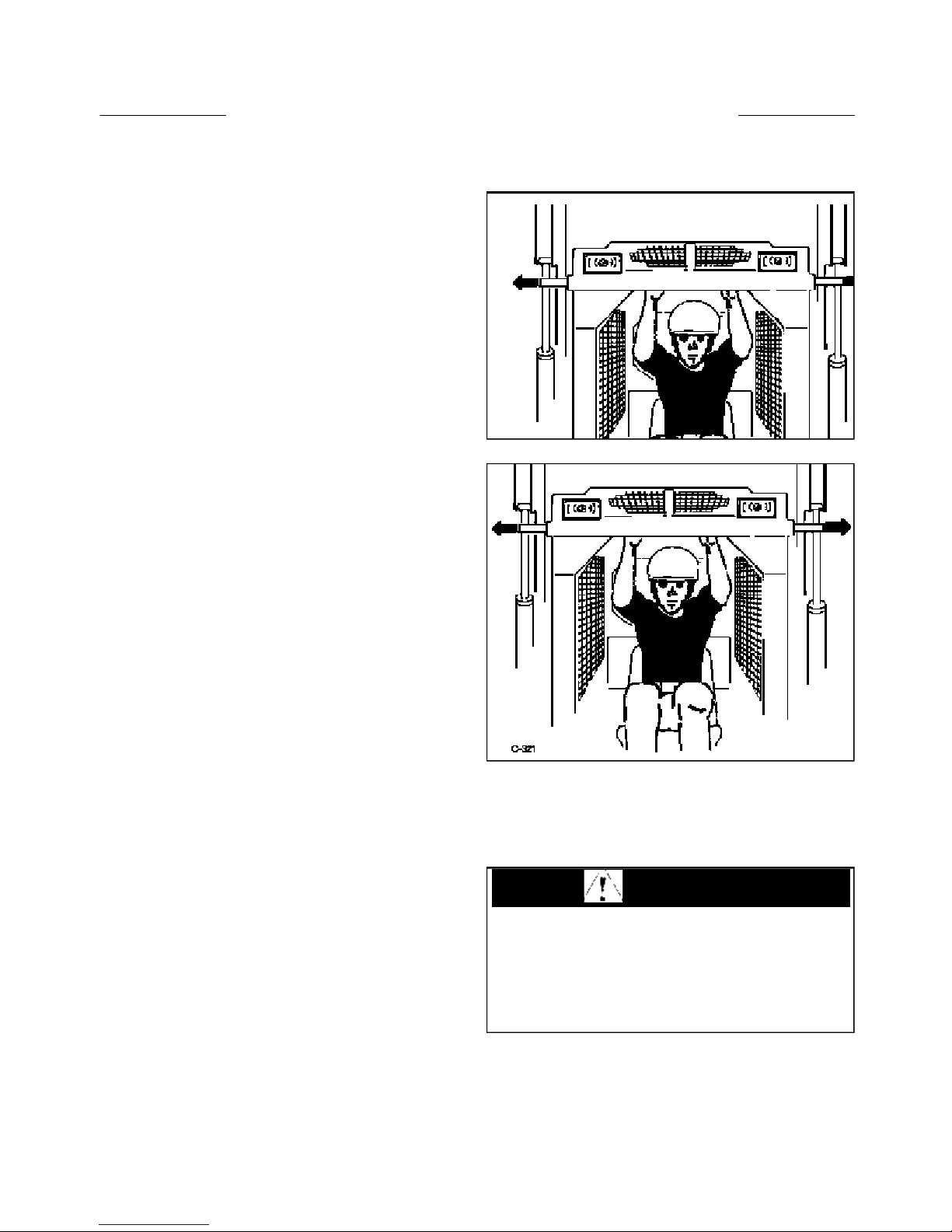
F. BOOM SUPPORTS
For safety while performing regular service or
maintenance work, the loader is equipped with boom
supports.
The boom supports, when extended, prevent the boom
arms from dropping if hydraulic pressure is relieved or
the foot control pedals are accidentally cycled.
To operate the boom supports, first remove any bucket or
attachment from the quick - tach; raise the boom arms to
full height and shut off the engine. Raise the boom
handles up and push out toward the boom arms to extend
the boom supports.
WARNING
To avoid personal injury, service the loader with the
arms down and the bucket or attachment on the
ground. If it is necessary to service the loader with
the boom arms raised be sure to engage the boom
supports. Never work under or around a loader with
raised boom arms without boom supports engaged.
8

TABLE OF CONTENTS
Section 1 Hydraulic System
Hydraulic Circuit . . . . . . . . . . . . . . . . . . . . . . . . . . . . . . . . . . . . . . .1.1
Gear Pump . . . . . . . . . . . . . . . . . . . . . . . . . . . . . . . . . . . . . . . . . . . .1.2
Control Valve . . . . . . . . . . . . . . . . . . . . . . . . . . . . . . . . . . . . . . . . . .1.3
Hydraulic Cylinders . . . . . . . . . . . . . . . . . . . . . . . . . . . . . . . . . . . . .1.4
Oil Filter . . . . . . . . . . . . . . . . . . . . . . . . . . . . . . . . . . . . . . . . . . . . . .1.5
Oil Cooler . . . . . . . . . . . . . . . . . . . . . . . . . . . . . . . . . . . . . . . . . . . . .1.6
Oil Reservoir . . . . . . . . . . . . . . . . . . . . . . . . . . . . . . . . . . . . . . . . . . .1.7
Trouble Shooting . . . . . . . . . . . . . . . . . . . . . . . . . . . . . . . . . . . . . . .1.8
Torque Chart . . . . . . . . . . . . . . . . . . . . . . . . . . . . . . . . . . . . . . . . . . .1.9
Conversion Chart . . . . . . . . . . . . . . . . . . . . . . . . . . . . . . . . . . . . . . .1.10
Section 2 Hydrostatic Drive System
Specifications.....................................................................................2.1
General Information...........................................................................2.2
Trouble Shooting ...............................................................................2.3
Pressure Tests.....................................................................................2.4
Towing Procedure ..............................................................................2.5
Flushing The Hydraulic System ........................................................2.6
Start - up Procedure ...........................................................................2.7
Gear Pump Replacement...................................................................2.8
Tandem Pump Replacement ..............................................................2.9
Tandem Pump Parts Diagram............................................................2.10
Drive Motor .......................................................................................2.11
Torque Specifications........................................................................2.12
Conversion Chart ...............................................................................2.13
Section 3 Final Drive
Specifications and Maintenance ........................................................3.1
Lubrication .........................................................................................3.2
Drive Chain........................................................................................3.3
Chain Tightener..................................................................................3.4
Drive Motor Sprocket........................................................................3.5
Axle Assembly...................................................................................3.6
Trouble Shooting ...............................................................................3.7
Section 4 Controls
Steering..............................................................................................4.1
Foot Pedals.........................................................................................4.2
Hand Controls ....................................................................................4.3
Throttle...............................................................................................4.4
Restraint Bar......................................................................................4.5
Parking Brake ....................................................................................4.6
Trouble Shooting ...............................................................................4.7
9

TABLE OF CONTENTS
Section 5 Electrical
Specifications . . . . . . . . . . . . . . . . . . . . . . . . . . . . . . . . . . . . . . . . . .5.1
Wiring Schematics . . . . . . . . . . . . . . . . . . . . . . . . . . . . . . . . . . . . . .5.2
Instrumentation . . . . . . . . . . . . . . . . . . . . . . . . . . . . . . . . . . . . . . . . .5.3
Ignition Switch . . . . . . . . . . . . . . . . . . . . . . . . . . . . . . . . . . . . . . . . .5.4
Engine Glow Plugs . . . . . . . . . . . . . . . . . . . . . . . . . . . . . . . . . . . . . .5.5
Battery . . . . . . . . . . . . . . . . . . . . . . . . . . . . . . . . . . . . . . . . . . . . . . . .5.6
Electrical Panel . . . . . . . . . . . . . . . . . . . . . . . . . . . . . . . . . . . . . . . . .5.7
Starter Circuit . . . . . . . . . . . . . . . . . . . . . . . . . . . . . . . . . . . . . . . . . .5.8
Charging Circuit . . . . . . . . . . . . . . . . . . . . . . . . . . . . . . . . . . . . . . . .5.9
Safety Circuit . . . . . . . . . . . . . . . . . . . . . . . . . . . . . . . . . . . . . . . . . .5.10
Auxiliary Circuit . . . . . . . . . . . . . . . . . . . . . . . . . . . . . . . . . . . . . . . .5.11
Accessory Circuit . . . . . . . . . . . . . . . . . . . . . . . . . . . . . . . . . . . . . . .5.12
Trouble Shooting . . . . . . . . . . . . . . . . . . . . . . . . . . . . . . . . . . . . . . .5.13
Section 6 Main Frame
Quick - Tach .......................................................................................6.1
Boom Arms........................................................................................6.2
Boom Support....................................................................................6.3
ROPS .................................................................................................6.4
Rear Door...........................................................................................6.5
Section 7 Engine
Maintenance .......................................................................................7.1
Cylinder Head ....................................................................................7.2
Replacement.......................................................................................7.3
Specifications.....................................................................................7.4
Trouble Shooting ...............................................................................7.5
Section 8 Maintenance & Specifications
Maintenance .......................................................................................8.1
Trouble Shooting ...............................................................................8.2
Special Tools ......................................................................................8.3
Specifications.....................................................................................8.4
Decals.................................................................................................8.5
10

SECTION 1 HYDRAULIC SYSTEM
1
Hydraulic Circuit 1.1
Layout . . . . . . . . . . . . . . . . . . . . . . . . . . . . . . . . . . . . . . . . . . . . . . . . . . . . . . . . . . . . . . . . . . pg. 1~2
Schematic . . . . . . . . . . . . . . . . . . . . . . . . . . . . . . . . . . . . . . . . . . . . . . . . . . . . . . . . pg. 1~3
Specifications . . . . . . . . . . . . . . . . . . . . . . . . . . . . . . . . . . . . . . . . . . . . . . . . . . . . . . . . . . . . pg. 1~4
Maintenance Schedule . . . . . . . . . . . . . . . . . . . . . . . . . . . . . . . . . . . . . . . . . . . . . . . . . . . . pg. 1~4
Gear Pump 1.2
General Information . . . . . . . . . . . . . . . . . . . . . . . . . . . . . . . . . . . . . . . . . . . . . . . . . . . . . .pg. 1~5
Replacing the Gear Pump . . . . . . . . . . . . . . . . . . . . . . . . . . . . . . . . . . . . . . . . . . . . . . . . . pg. 1~6
Gear Pump Disassembly . . . . . . . . . . . . . . . . . . . . . . . . . . . . . . . . . . . . . . . . . . . . . . pg. 1-7 ~ 10
Gear Pump Reassembly . . . . . . . . . . . . . . . . . . . . . . . . . . . . . . . . . . . . . . . . . . . . . pg. 1-11 ~ 13
Control Valve 1.3
Testing / Adjusting the Relief Valve . . . . . . . . . . . . . . . . . . . . . . . . . . . . . . . . . . . pg. 1-14 ~ 15
Control Valve Replacement . . . . . . . . . . . . . . . . . . . . . . . . . . . . . . . . . . . . . . . . . . pg. 1-15 ~ 16
Exploded Illustration Diagram . . . . . . . . . . . . . . . . . . . . . . . . . . . . . . . . . . . . . . . . pg. 1-17 ~ 18
Control Valve Disassembly / Repair(175) . . . . . . . . . . . . . . . . . . . . . . . . . . . . . . pg. 1-19 ~ 24
Control Valve Dissassembly/Repair(1700) . . . . . . . . . . . . . . . . . . . . . . . . . . . . . . .pg. 1-25~28
Hydraulic Cylinders 1.4
General Information . . . . . . . . . . . . . . . . . . . . . . . . . . . . . . . . . . . . . . . . . . . . . . . . . . . . . .pg. 1~29
Testing Piston Seals . . . . . . . . . . . . . . . . . . . . . . . . . . . . . . . . . . . . . . . . . . . . . . . . . . . . . . pg. 1~30
Lift Cylinder Replacement . . . . . . . . . . . . . . . . . . . . . . . . . . . . . . . . . . . . . . . . . . . . . . . . pg. 1~31
Tilt Cylinder Replacement . . . . . . . . . . . . . . . . . . . . . . . . . . . . . . . . . . . . . . . . . . . . . . . . pg. 1~32
Cylinder Disassembly . . . . . . . . . . . . . . . . . . . . . . . . . . . . . . . . . . . . . . . . . . . . . . . . pg. 1-33 ~ 34
Cylinder Inspection . . . . . . . . . . . . . . . . . . . . . . . . . . . . . . . . . . . . . . . . . . . . . . . . pg. 1-35
Cylinder Assembly . . . . . . . . . . . . . . . . . . . . . . . . . . . . . . . . . . . . . . . . . . . . . . . . . . pg. 1-35 ~ 36
Hydraulic Oil Filter 1.5
General Information . . . . . . . . . . . . . . . . . . . . . . . . . . . . . . . . . . . . . . . . . . . . . . . pg. 1~37
Filter Replacement . . . . . . . . . . . . . . . . . . . . . . . . . . . . . . . . . . . . . . . . . . . . . . . . pg. 1~37
Hydraulic Oil Cooler 1.6
General Information . . . . . . . . . . . . . . . . . . . . . . . . . . . . . . . . . . . . . . . . . . . . . . . .pg. 1~38
Oil Cooler Replacement . . . . . . . . . . . . . . . . . . . . . . . . . . . . . . . . . . . . . . . . . . . . . . . . . .pg. 1~38
Hydraulic Oil Reservoir 1.7
General Information . . . . . . . . . . . . . . . . . . . . . . . . . . . . . . . . . . . . . . . . . . . . . . . pg. 1~39
Checking the Oil Level . . . . . . . . . . . . . . . . . . . . . . . . . . . . . . . . . . . . . . . . . . . . . pg. 1~39
Adding Oil . . . . . . . . . . . . . . . . . . . . . . . . . . . . . . . . . . . . . . . . . . . . . . . . . . . . . . . pg. 1~39
Servicing the Reservoir . . . . . . . . . . . . . . . . . . . . . . . . . . . . . . . . . . . . . . . . . . . . . pg. 1~40
Trouble Shooting 1.8
Trouble Shooting Chart . . . . . . . . . . . . . . . . . . . . . . . . . . . . . . . . . . . . . . . . . pg. 1-41 ~ 42
Torque Chart 1.9
Torque Chart . . . . . . . . . . . . . . . . . . . . . . . . . . . . . . . . . . . . . . . . . . . . . . . . . . . . . pg. 1~42
Conversion Charts 1.10
Conversion Charts . . . . . . . . . . . . . . . . . . . . . . . . . . . . . . . . . . . . . . . . . . . pg. 1-43 ~ 1-45
1-1
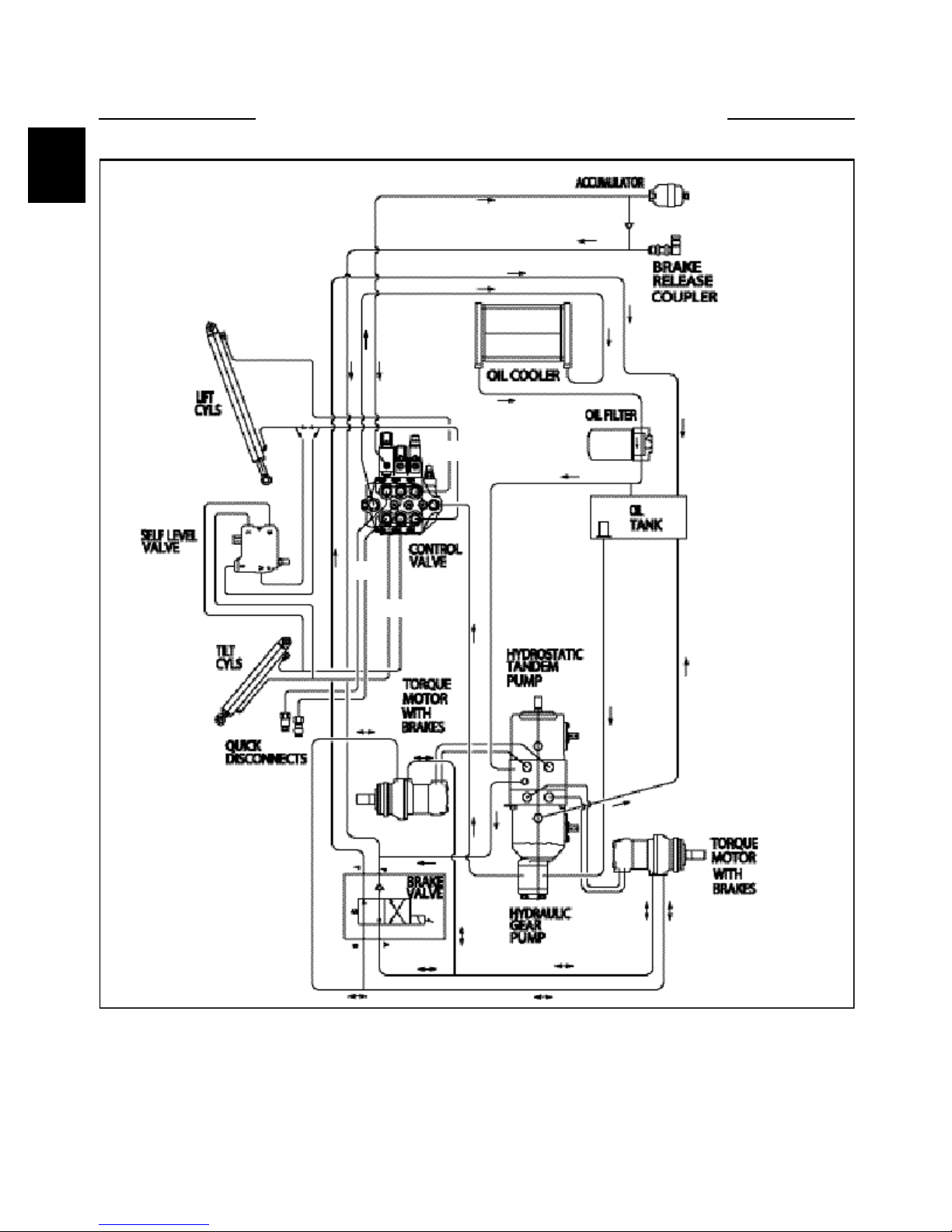
HYDRAULIC LAYOUT 1.1
C C
AA
B B
C4165
A Auxiliary Circuit
B Tilt Circuit
C Lift Circuit
NOTE: Foot pedal control operated machine illustrated.
Items (A3 / B3) are reversed for hand control operated
machines.
Hydraulic fluid comes out the port closest to the spool
end of the valve when the spool is pushed in.
Hydraulic fluid received at the fixed end of the cylinder
pushes it out. When the hydraulic cylinder receives fluid
at the ram (rod) end, it retracts.
1-2
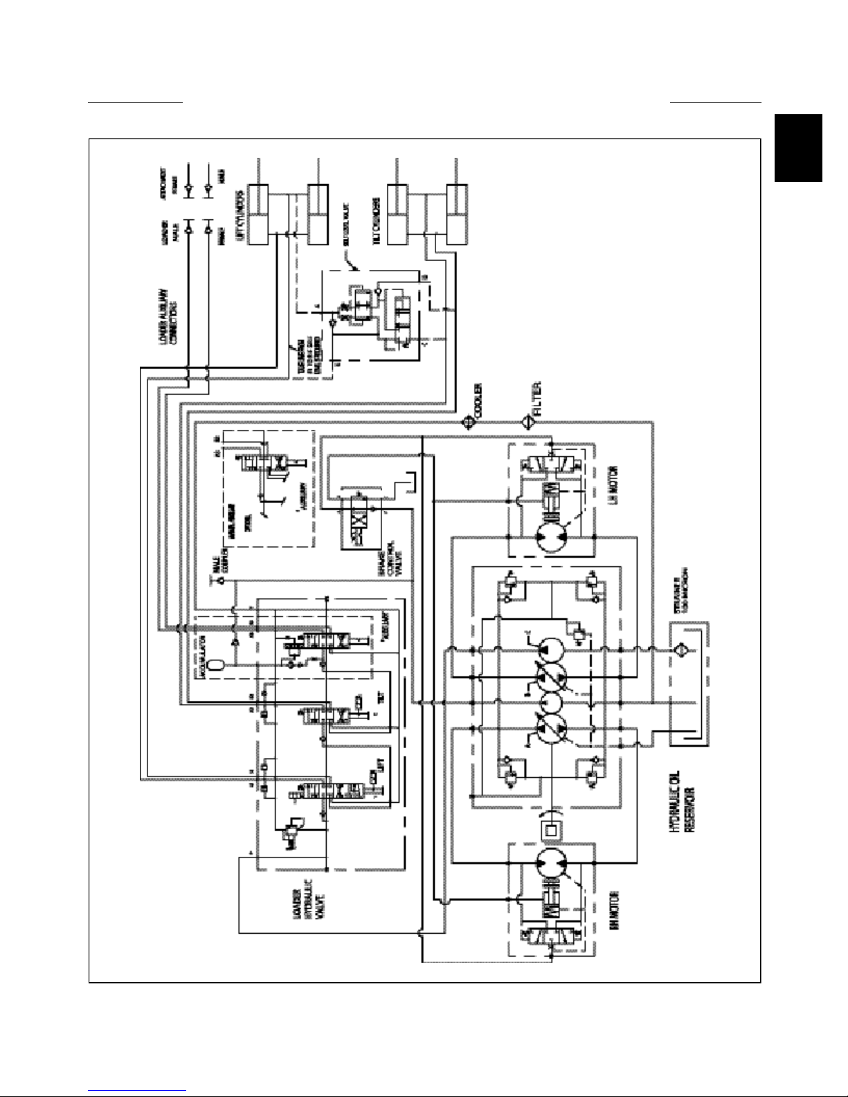
HYDRAULIC SCHEMATIC 1.1
1
C4191
1-3

SPECIFICATIONS & MAINTENANCE 1.1
Hydraulic Specifications
Pump Type . . . . . . . . . . . . . . . . . . . . . . . . . . . . . . . . . . . . . . . . . . . . Gear, 1.37 cu. in. (22.4cc)
Pump Brand . . . . . . . . . . . . . . . . . . . . . . . . . . . . . . . . . . . . . . . . . . . . . . . . . . Sauer Sundstrand
Pump Capacity . . . . . . . . . . . . . . . . . . . . . . . . . . . . . . . . . . . . . . . . . . . 16.6 GPM (62.8 LPM)
Rated Speed . . . . . . . . . . . . . . . . . . . . . . . . . . . . . . . . . . . . . . . . . . . . . . . . . . . . . . . 2800 RPM
Control Valve . . . . . . . . . . . . . . . . . . . . . . . . . . . . . . . . . . . . . . . . . . . . . . . . . . . . . Series Type
Main Relief Pressure . . . . . . . . . . . . . . . . . . . . . . . . . . . . 2400 PSI (165.5 Bar) @ Zero Flow
Reservoir Capacity . . . . . . . . . . . . . . . . . . . . . . . . . . . . . . . . . . . . 14.8 US Gallons (56 Liters)
Fluid Type . . . . . . . . . . . . . . . . . . . . . . . . . . . . . . . . . . . . . . . . . . . . . . . . . . 10W30 API SJ Oil
Reservoir Filtration . . . . . . . . . . . . . . . . . . . . . . . . . . . . . . . . . . . . . . . . . . . . . . . . . 100 Micron
System Filtration . . . . . . . . . . . . . . . . . . . . . . . . . . . . . . . . . . . . . . . . . . . . . . . . . . . . . 5 Micron
Oil Cooler . . . . . . . . . . . . . . . . . . . . . . . . . . . . . . . . . . . . . . . . . . . . . . . . . . . . . . . . . . 650 BTU
Lift Cylinders (STD) . . . . . . . . . . . . . . . . . . . . . . . . . . . . . . . . . . . . . . (2) 2.5’’ Bore Diameter
Lift Cylinder Rods (STD) . . . . . . . . . . . . . . . . . . . . . . . . . . . . . . . . . . . . . . . . . . 1.5’’ Diameter
Tilt Cylinders . . . . . . . . . . . . . . . . . . . . . . . . . . . . . . . . . . . . . . . . . . (2) 2 1/2’’ Bore Diameter
Tilt Cylinder Rods . . . . . . . . . . . . . . . . . . . . . . . . . . . . . . . . . . . . . . . . . . . . . . . 1.5’’ Diameter
Lift Cycle Cyl. + / - 1.5 seconds (Up / Down) T175 . . . . . . . . . . . . . . . . . . . . . . . . 5.50 / 3.56
Lift Cycle Cyl. + / - 1.5 seconds (Up / Down) 1700 . . . . . . . . . . . . . . . . . . . . . . . . . . 4.6 / 3.0
Tilt Cycle + / - 1.5 seconds (Up / Down) T175 . . . . . . . . . . . . . . . . . . . . . . . . . . . . 1.84 / 2.61
Tilt Cycle + / - 1.5 seconds (Up / Down) 1700 . . . . . . . . . . . . . . . . . . . . . . . . . . . . 1.73 / 2.28
Lift & Tilt Cycle Cyl., + / - 1.5 seconds (Up & Out) . . . . . . . . . . . . . . . . . . . . . . . . . . . . 5.25
Lift & Tilt Cycle Cyl., + / - 1.5 seconds (Down & In) . . . . . . . . . . . . . . . . . . . . . . . . . . . 4.55
Allowable Drop, Measured at the Cylinder Rod, Engine Off,
@ Rated Capacity and Operating Temperature . . . . . . . . . . . . . . . . 1.5’’ (38mm) / 3 Minutes
Maintenance Schedule . . . . . . . . . First (HRS) . . . . Every (HRS)
Oil level check . . . . . . . . . . . . . . . . . . . . . . . . . . . . . . . . 8 . . . . . . . . . . . . . . . . . . . . . 8
Oil filter change . . . . . . . . . . . . . . . . . . . . . . . . . . . . . . 50 . . . . . . . . . . . . . . . . . . . . 150
Oil cooler clean . . . . . . . . . . . . . . . . . . . . . . . . . . . . . . . 8 . . . . . . . . . . . . . . . . . . . . . 8
General system check
( leaks etc. ) . . . . . . . . . . . . . . . . . . . . . . . . . . . . . . . . . . 8 . . . . . . . . . . . . . . . . . . . . . 8
Cylinders, lubricate . . . . . . . . . . . . . . . . . . . . . . . . . . . . 8 . . . . . . . . . . . . . . . . . . . . . 8
Control valve relief filter . . . . . . . . . . . . . . . . . . . . . . . 500 . . . . . . . . . . . . . . . . . . . 1000
Reservoir filters change . . . . . . . . . . . . . . . . . . . . . . . 1000 . . . . . . . . . . . . . . . . . . 1000
Hydraulic oil change . . . . . . . . . . . . . . . . . . . . . . . . . 1000 . . . . . . . . . . . . . . . . . . 1000
1-4
GENERAL INFORMATION 1.2
1
Refer to figure C2018 on page 1-2.
Oil is drawn from the hydraulic oil reservoir through a
100 micron element. From there it travels to the main
hydraulic pump.
• The hydraulic pump is a gear type which is driven by a
shaft and coupler through the hydrostatic drive pump at
engine speed. The oil then flows from the gear pump to
the hydraulic control valve.
• The hydraulic control valve is equipped with an
adjustable relief valve which is adjusted to 2400 PSI
(165.5 Bar). The control valve is a series type with 3
spools (banks). The various spools activate the boom,
bucket and auxiliary hydraulic functions.
When the spools are in neutral, oil flows from the
hydraulic gear pump, through the control valve and
returns to the hydraulic cooler, to the 5 micron hydraulic
filter. From the hydraulic filter, the fluid flows to charge
the tandem hydrostatic pump and pressurize the hydraulic
brake release system and then back to the hydraulic
reservoir. As a spool is moved, oil is directed to one of
the valve ports and oil flows out to operate a function.
The return oil coming back from this operation is ported
to the next valve section which allows operation of more
than 1 function at the same time. This is a series type
valve function.
Each spool end contains a centering spring which returns
the spool to neutral when the foot pedal, or control
handle, is released.
• The boom section, on foot control operated loaders, has
a detent mechanism to hold the spool in the float position.
The auxiliary section is operated by foot pedal operation,
or may have an optional electrical solenoid operated
control, and may be engaged momentarily by the control
lever mounted switch, forward or reverse, or by engaging
the dash mounted toggle switch for constant power in the
forward direction only.
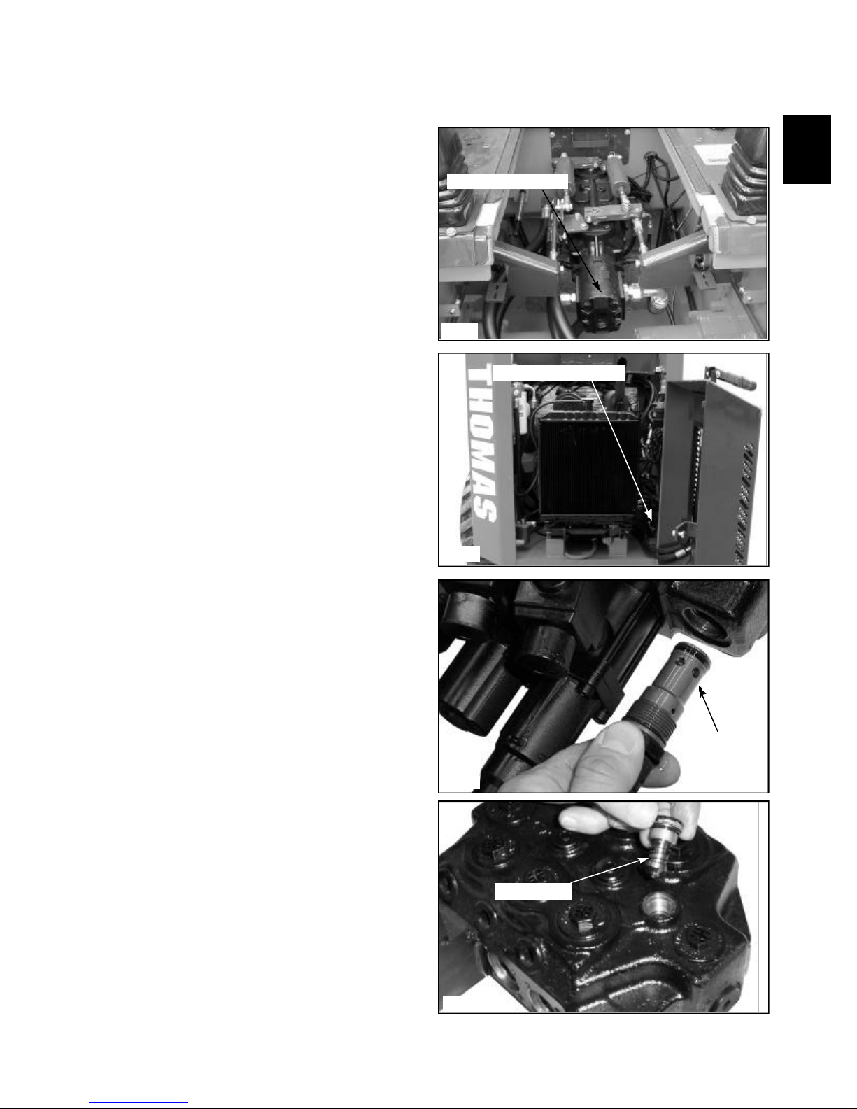
The system relief valve operates when ever a hydraulic
function has been restricted or overloaded (fig. C3746).
To protect against excessive pressure build up, the relief
valve opens and allows oil to return to the return outlet.
The system relief valve is adjustable, and is preset at
2400 PSI. (165.5 Bar)
• Load check valves are located between the ports of
each spool circuit. The function of the load check valve is
to hold the boom arms or bucket in position during initial
spool movement (fig. C3717).
Gear pump location
C3426
Control valve location
C3427
Relief Valve
C3746
Check Valve
1-5
C3717
GEAR PUMP 1.2
Replacement
Start the gear pump removal procedure by removing any
attachment, raising the boom arms and engaging the
boom support pins. Shut off the engine.
WARNING
To prevent personal injury do not work under the
boom arms without the boom supports engaged.
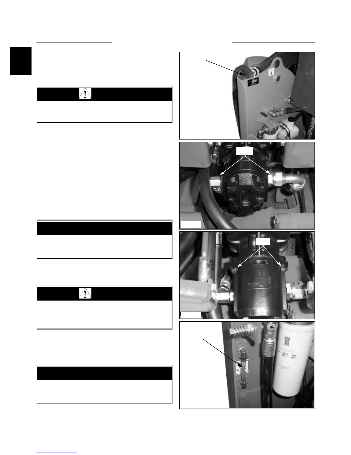
1 Remove the seat and hydrostatic shield.
2 Attach a vacuum system to the hydraulic oil reservoir
filler location. ( fig. C3428 ) Or drain the oil reservoir.
Seal the threads on the drain plug, if removed, with teflon
tape or a liquid form of pipe sealant before re - installing.
3 Disconnect the hydraulic hoses from the gear pump.
( fig. C3429 ) Remove the pump fittings. Cap all open
hoses to prevent contamination. After capping ends you
may unhook vacuum system from oil reservoir.
4 Remove the 2 bolts holding the gear pump to the
hydrostatic tandem section. ( fig. C3430) Remove the
gear pump.
5 Replace gear pump in reverse order.
Reservoir filler spout
C3428
Hoses
IMPORTANT
If gear pump replacement is being done because of
failure, the hydraulic system and oil should be
checked for contamination.
6 If the hydraulic system has been contaminated by
pump or other failure you must follow the cleaning
procedure outlined in section 2.7.
WARNING
Use caution when dealing with hydraulic fluid under
pressure. Escaping fluid under pressure can
penetrate the skin and cause serious injury.
7 Start the engine and check for leaks. Do not use your
hands to find leaks.
8 Check the fluid level in the hydraulic oil reservoir
and replenish as required. (fig. C3431)
IMPORTANT
When making repairs to the hydraulic system, keep
the work area and parts clean. Use caps and plugs
on all open lines and ports.
C3429
Bolts
C3430
Oil level
C3431
1-6
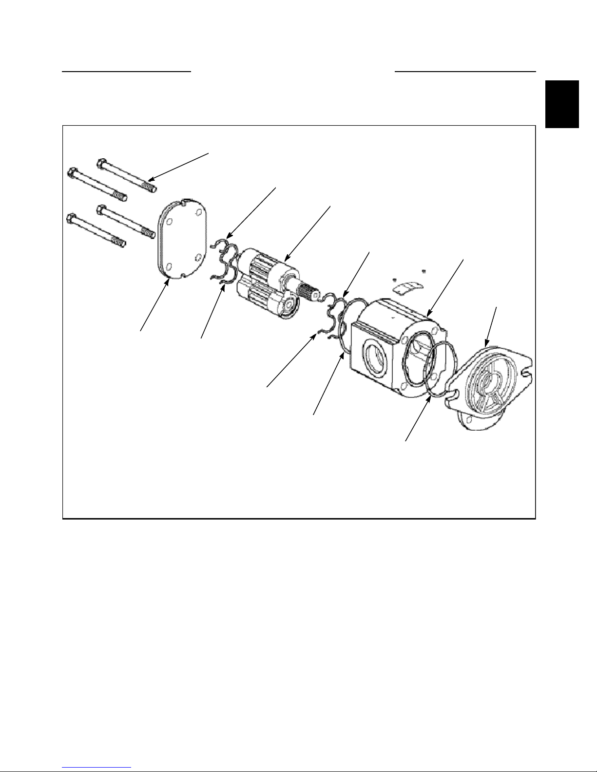
Disassembly
1
GEAR PUMP 1.2
1
3
5
C3835
3
2
4
4
6
6
7
8
1. Screws
2. Rear Cover
3. Backing Strip
4. Moulded Seal
5. Drive Gear
6. O-Ring Seal
7. Body
8. Front Plate
1-7

GEAR PUMP 1.2
Disassembly (continued)
1. General
The following is a detailed procedure for dissambly
and assembly of the SP2.5 pumps. Prior to proceeding it
may be necessary to prepare some subassemblies
seperately. The details for preparing each subassembly are
given in the following section, as well as some general
recommendations.
2. Cleanliness
Cleanliness is the primary factor for reliable pump
performance. Wash the outside of the pump thoroughly
before disassembly and all pieces prior to assembly.
Cleaning parts with clean shop solvent and air drying is
usually adequate.
3. Lubrication Of Moving Parts
During assembly, it is imperative to provide
lubrication with clean hydraulic oil to all the running
parts of the pump. It is also necessary to coat the seals
with grease. The absence of lubrication during assembly
can cause the unit to seize after a few minutes of running.
4. Care Of Surface Treatment
Be careful when handling all the internal surfaces,
especially bearings, gears, and body faces. Do not touch
or score them with metal tools or cutting edges.
5. Marking The Parts
Mark the parts before completely disassembling a
pump. The marks allow components to be reassembled in
the same relative position. This action should be applied
to the body, bearings, and gears. Scribing, bluing, or
using a felt pen to mark the outside of the body on the
inlet side is suggested to indicate the relative position of
the front flange and the rear cover to the body. Mark the
bearing blocks also on the inlet side and the gears
position relative to each other. DO NOT scribe internal
surfaces.
IMPORTANT
Mark all peices during disassembly so that the unit
can be reassembled correctly. Installing components
incorrectly could severly damage the unit and/or
cause it to not function properly.
1-8
GEAR PUMP 1.2
1
Disassembly (continued)
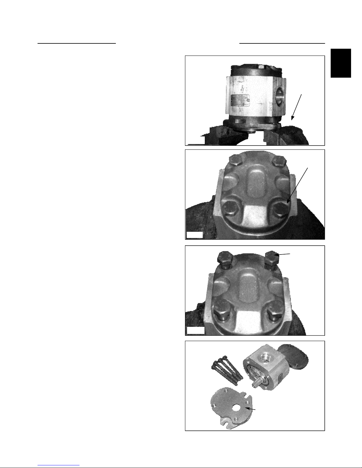
6. Procedure
1. Clamp the unit in a vice from the flange side
(fig. C3973). Make sure the vice jaws are clean and
have smooth surfaces to prevent damage to the
pump. Clamping the pump body is not recommended
because serious damage to the surfaces, on which the
ports are located, may occur.
2. Use a 19mm socket wrench to loosen the four
bolts on the rear cover (fig. C3974). Next completely
unscrew the bolts and remove them. Inspect the
threads for damage (fig. C3975).
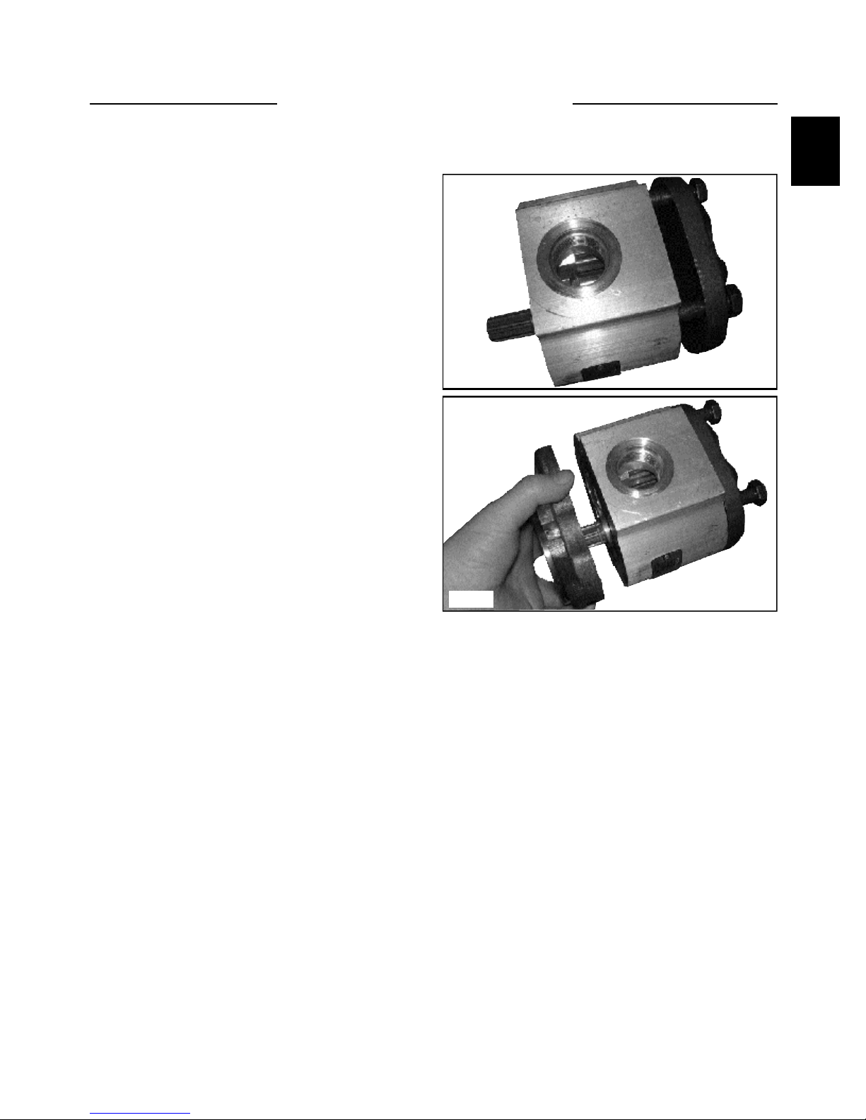
3. Place the pump on the table and slowly remove
the front flange (fog. C3976). Note, some units have
a shaft seal and others do not. Should your unit have
the shaft seal, be careful not to damage it when
removing the front flange. Inspect the front flange
and seal area.
Vice
C3973
Bolts
C3974
Remove and
inspect for
damage.
C3975
Front Flange
C3976
1-9
GEAR PUMP 1.2
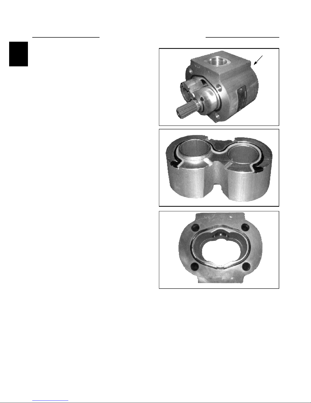
Disassembly (continued)
6. Procedure
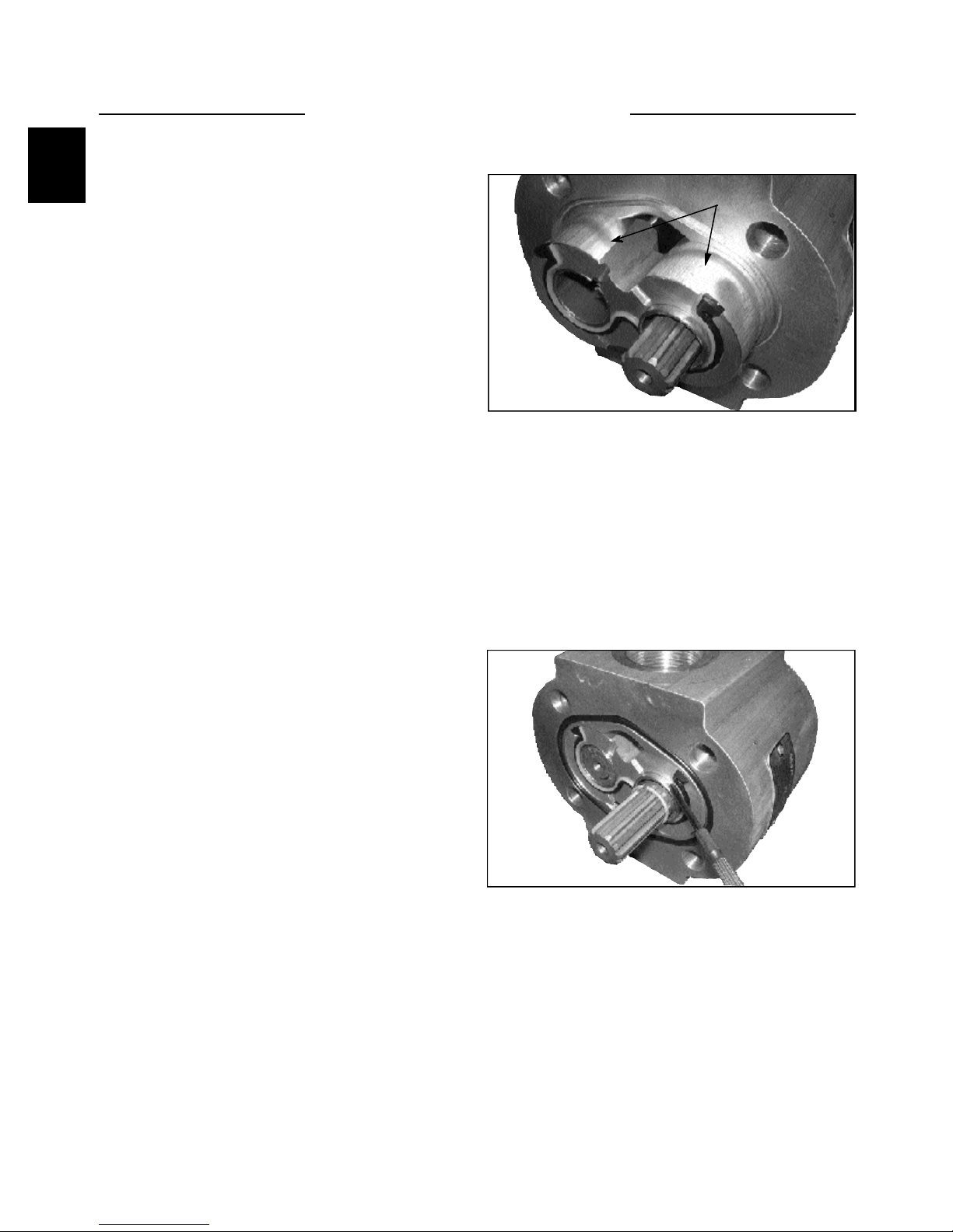
4. Place the pump on it’s side. While disassembling
the unit, you need to mark the relative positions of
the gear mesh (drive gear tooth and idler gear tooth)
and the bearing blocks to the body so they can be
reassembled in the same position. Carefilly remove
the bearing block and gear set (fig. C3977).To
accomplish this, hold the pump body and push with
your fingers on the rear bearing block.
5. Remove the pressure seals taking note how the
pressure seals and teflon back up ring are installed
(fig. C3978). Check the seal quality. Replacement is
recommended whenever there are burrs, evidence of
extrusion, or marks caused by overheating. Carefully
remove the seals from the bearing blocks beginning
with the back up ring then the pressure seal (fig.
C3979). Do not use tools with sharpe edges to
remove the seals, as damage to the bearing blocks
can result. Dispose of any damaged seals.
6. Removal of the outer o-ring seals. Check the
quality of these two seals. If necessary, replace. Do
not use tools with sharp edges to remove the seals, as
damage to the housing may result. Disgard any
damaged seals.
Push
C3977
C3978
7. Remove the shaft seal in the front flange (if
applicable). Place the flange on the work surface.
Using internal snap ring pliers, remove the snap ring.
Check the seal quality and remove it if necessary. To
remove, pry the bottom of the shaft seal and force it
out while rotating the flange to lift it out evenly. Do
not use the flange pilot to gain leverage as damage
may result. Use a plastic rod or wooden dowel as a
fulcrum. After removal, dispose of the damaged seal.
C3979
GEAR PUMP 1.2
1
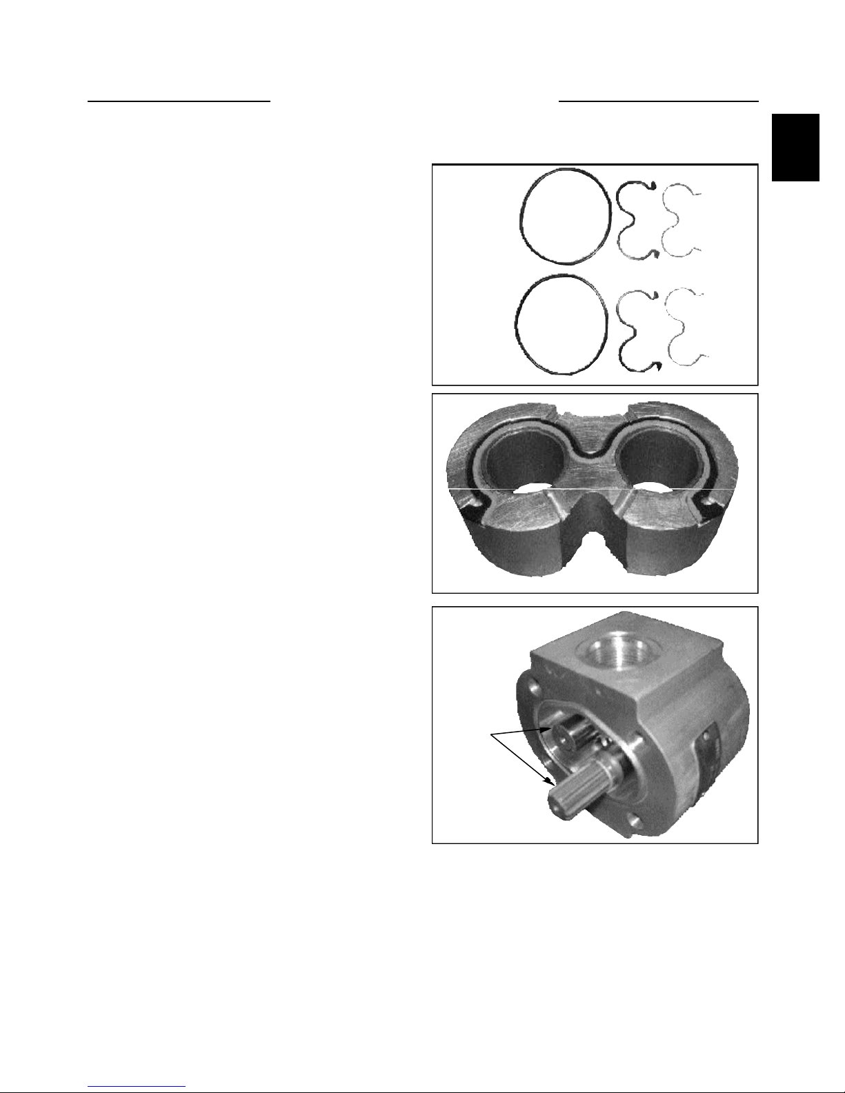
Assembly
1. Have the entire seal kit available and layed out
neatly on the table (fig. C3980). Compare the old
seal kit to the new one to ensure you have the correct
one. Lightly coat all seals with seal grease. The
grease is needed to adhere the sealsin their grooves.
DO NOT INSTALL DRY SEALS!
2. Install the shaft seal into the front flange (if
applicable). Prepare the flange and shaft seal by
lightly lubricating with grease. Seat the seal in the
flange by hand. Then, using a shaft seal installation
tool press the seal until the tool stops on the flange.
This will insure the seal is inserted to the proper
depth.
3. Install the snap ring using internal snap ring
pliers (fig. 3981). Ensure the snap ring fits securely
in its groove. This is necessary to retain the shaft
seal.
C3980
4. Prepare the body by cleaning it. Inspect the
internal and mating surfaces. Ensure the surfaces are
free of burrs and scratches. Check both the bearing
block mating surface and the cut-in path.
5. Prepare the gears (fig. C3982). Caution, the gear
surfaces are superfinished. Residue on hands and
fingers may be corrosive to this surface. DO NOT
TOUCH. Carefully clean the two gears. Inspect the
journals and the flat faces on the top and bottom of
the gears. Ensure these surfaces are free from burrs
or scratches. If scratches are found, clean them with a
flat stone and/or very fine emery paper. Rewash the
gears after this operation.
C3981
Gears
C3982
1-11
Assembly
GEAR PUMP 1.2
6. Prepare the bearing blocks by cleaning both
blocks (fig. C3983). Inspect the flat surfaces of the
bearing blocks for burrs or scratches on the edges. If
necessary, remove burrs with very fine emery paper.
Then rewash the bearings. Inspect the DU bushings
for wear. There should be no bronze showing. Using
clean hydraulic oil, lubricate the internal and external
surfaces of your blocks.
7. Assemble the bearing blocks and gears.
Lubricate the journals and gear faces. Assemble the
bearing blocks and gears in the same orientation that
it was disassembled. Align all marks made during
disassembly. Ensure the front and rear block occupy
the same location with respect tot he housing as they
did before disassembly. Misalignment of the gear
teeth may increase operating noise.
8. Install the gear and block assembly into the body
of the cavity. Align the assembly marks to ensure that
the gear block assembly is installed with the same
orientation as before assembly.
Blocks
C3983
9. Once the gears and the bearing blocks are
installed into the housing, clean the mating surfaces.
Remove any excess lubrication and grease from the
mating surfaces of the pump body. Ensure that these
surfaces are dry and free of contamination before
moving on to the next step. Install the o-rings and
back-up rings on both the bearing blocks and the
housing (fig. C3984).
C3984
1-12
GEAR PUMP 1.2
1
Assembly
10. Remove any axcess lubrication and grease from
the mating surfaces of the front flange and rear cover.
Ensure that these surfaces are dry and free of
contamination before moving on to the next step.
11. Install the four bolts through the rear cover then
slide the assembly onto the rear of the housing (fig.
C3985). Before you slide the cover against the
housing, check to make sure all o-rings and the backup seal are seated properly with no foreign material
on them. If they get pinched or there is foreign
material on an o-ring, you may get internal or
external leakage.
12. Install the front cover (fig. C3986). While
keeping pressure on the front flange and the rear
cover so the o-rings wont move out of place, set the
unit in a vise with the front in the jaws.
13. Torque the four bolts by criss crossing back and
forth a little at a time until you reach the final torque.
C3985
14. After the pump has been disassembled and
reassembled it it suggested that the pump be run in
and tested on an appropriate test stand. This is done
to verify the volumetric efficiency and the integrity
of the unit.
C3986
1-13
CONTROL VALVE 1.3
Testing and Adjusting the Relief Valve Pressure
Hoses and gauges required for this test must be capable
of withstanding 5000 PSI (207 Bar) continuous pressure,
and hydraulic flow meter capable of measuring 30 gallons
per minute. (113 LPM) (fig. C3432) This test also
checks the status of the gear pump capacities.
Pressure fluctuations may be caused by restricted oil flow
through the relief valve. The relief valve filter may need
serviced as outlined in the control valve disassembly
section on pages 1-9 through 1-13.
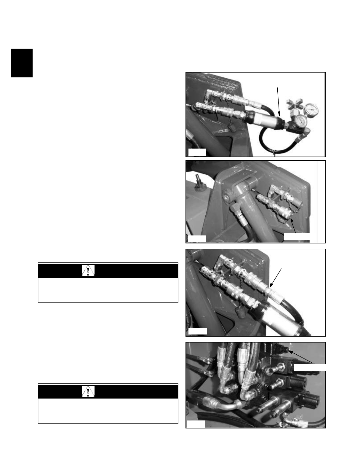
1 Install the flow meter / pressure tester to the auxiliary
hydraulic quick couplers. The female coupler attached to
the loader provides the power out when the auxiliary
control is engaged. (fig, C3646) Connect the flow meter
and pressure gauge inlet side to match the power out of
the female auxiliary coupler to prevent meter and gauge
damage. Be sure to connect a return line to the male
auxiliary hydraulic quick coupler. (fig. C3433)
2 Start the engine and engage the auxiliary hydraulic
system. Increase the engine speed to full operating RPM.
(See Section 7 for checking and adjusting engine speed to
2800 RPM plus or minus 25 RPM)
3 Turn the flow control valve on the flow meter to
restrict the oil flow down to 2 GPM. (7.5 LPM) As you
are turning the flow control valve, watch the pressure
gauge and make sure it does not go over 3000 PSI.(207
Bar) Stop further adjustment immediately if the reading
goes over this setting. Shut off the auxiliary hydraulic
CAUTION
Adjusting the relief valve setting too high may cause
damage to the gear pump.
C3432
C3646
Flow Meter/Pressure Tester
Pressure out
Pressure return
system and shut off the engine. Move to step 6 to make
initial setting.
WARNING
To prevent personal injury or damage to the loader,
do not adjust the relief valve while the engine is
operating.
C3433
Relief valve
C3434
1-14
CONTROL VALVE 1.3
1
4 Repeat steps 2 and 3 if necessary. Allow the loader to
operate at this setting until the oil temperature has
increased to 160° F (71ºC), operating temperature.
5 Turn the flow control valve further to restrict the oil
flow to no flow. (Zero) Correct pressure setting is 2400
PSI +/- 100 PSI. (165 Bar, +/-6.9 Bar)
6 If adjustment is necessary, shut down the auxiliary
hydraulic system, shut off the engine and return the flow
control valve to the open position. Locate the control
valve in the engine compartment.
7 Loosen the jam nut on the relief valve adjusting
screw and turn the screw clockwise, counting the turns,
until the screw bottoms out. (fig. C3435)
8 Turn the screw back out lesser turns than you turned
in to increase pressure, or out more turns to decrease
pressure.
9 Retake the pressure readings by performing steps 2
through 5. If necessary make further adjustments by
repeating steps 6 through 9.
NOTE: If inadequate pressure and / or flow is not
available, the gear pump could be failing, the intake to
the gear pump is restricted, or the filter in the relief
valve is clogged. (See pg. 25 for filter replacement).
Jam nut
Relief valve
C3869
Solenoid coil
mounting nuts
C3436
Control Valve Replacement
1 Remove any attachment and shut off the engine
IMPORTANT
Clean the work area prior to repair. Cap all open
lines, fittings and ports to prevent contamination.
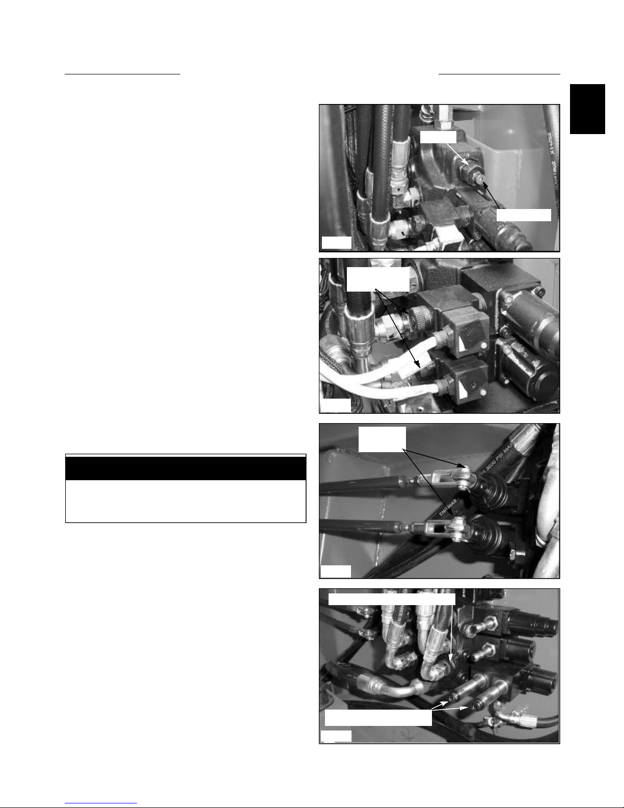
2 Disconnect the control cables, electrical solenoid
spool locks, and electrical auxiliary solenoid wiring
connectors if equipped. (fig. C3436, C3437)
3 Disconnect the the inlet hose coming from the gear
pump.Cap the hose and fitting and remove the adapter
fitting in the control valve. (fig. C3436)
4 Disconnect the 6 hoses going to the boom, bucket
and auxiliary circuits. Marking the hoses as you remove
them is recommended to ease re-assembly and assure the
circuits are functioning properly at restart.(fig. C3434)
5 Disconnect the return line from the control valve and
remove the adapter fitting. Plug and cap all open ports
and hose ends. (fig. C3436)
Cable
cotter pins
C3437
Remove and tag hose location
Solenoid Coils Removed
1-15
C3434
CONTROL VALVE 1.3
6 Remove the 3 nuts holding the control valve to the
mount and remove the control valve.
7 Remove any fittings left in the control valve. Cap all
open ports to prevent contamination. Place these fittings
in the new or repaired control valve. Be sure to check all
fitting flares and o -rings for damage and replace as
required.
IMPORTANT
Follow the hydraulic fitting torque chart in Section
1.10 when connecting fittings and lines.
8 Assemble the control valve to the loader in the
reverse order above. Torque the bolts holding the control
valve to the mount at 15 ft / lbs. (20.4 N.m.)
11 After all connections have been made, including the
control valve electrical connections, check the oil level in
the hydraulic reservoir and top off if necessary.
12 Start the engine and cycle the various hydraulic
functions to check for leaks. Make sure the control valve
lock system is functioning properly. Do not use your
hands to check for leak locations, fluid under operating
pressure can penetrate the skin and cause serious personal
injury.
WARNING
Use extreme caution when checking the hydraulic
system for leaks. Fluid under pressure can penetrate
the skin and cause serious injury.
Valve mount plate
C3438
Check fluid level
C3431
Replenish fluid as required
13 After checking for leaks, you must retest the relief
valve setting as outlined on page 1-6 Testing and
adjusting.
WARNING
All safety switches must be connected and
functioning to prevent possible operator injury.
C1108
1-16
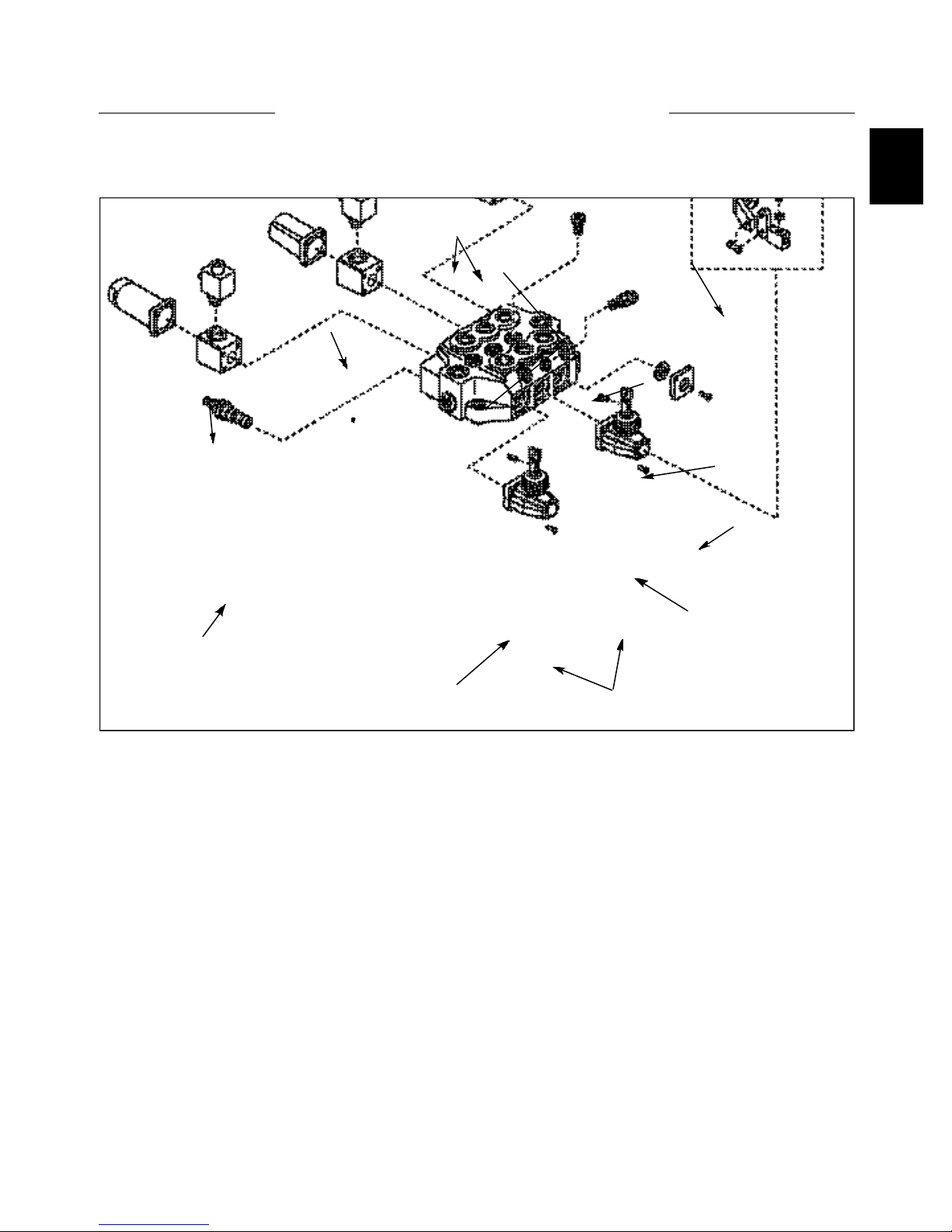
CONTROL VALVE 1.3
1
Control Valve Disassembly (175)
7
6
11
8
6
5
C3240
Diagram Legend
1. Control Box
2. Set Screws
3. Dust Cap Ass’y Kit
4. Check Valve
5. Main relief Valve
6. Lock Solenoid Coil
7. Auxiliary Solenoid Coil
8. Auxiliary Control With Coils
9. Port Relief Valve
10. Bar
11. Dust Cap With Connector For Hand Controls
4
9
3
10
2
1
1-17
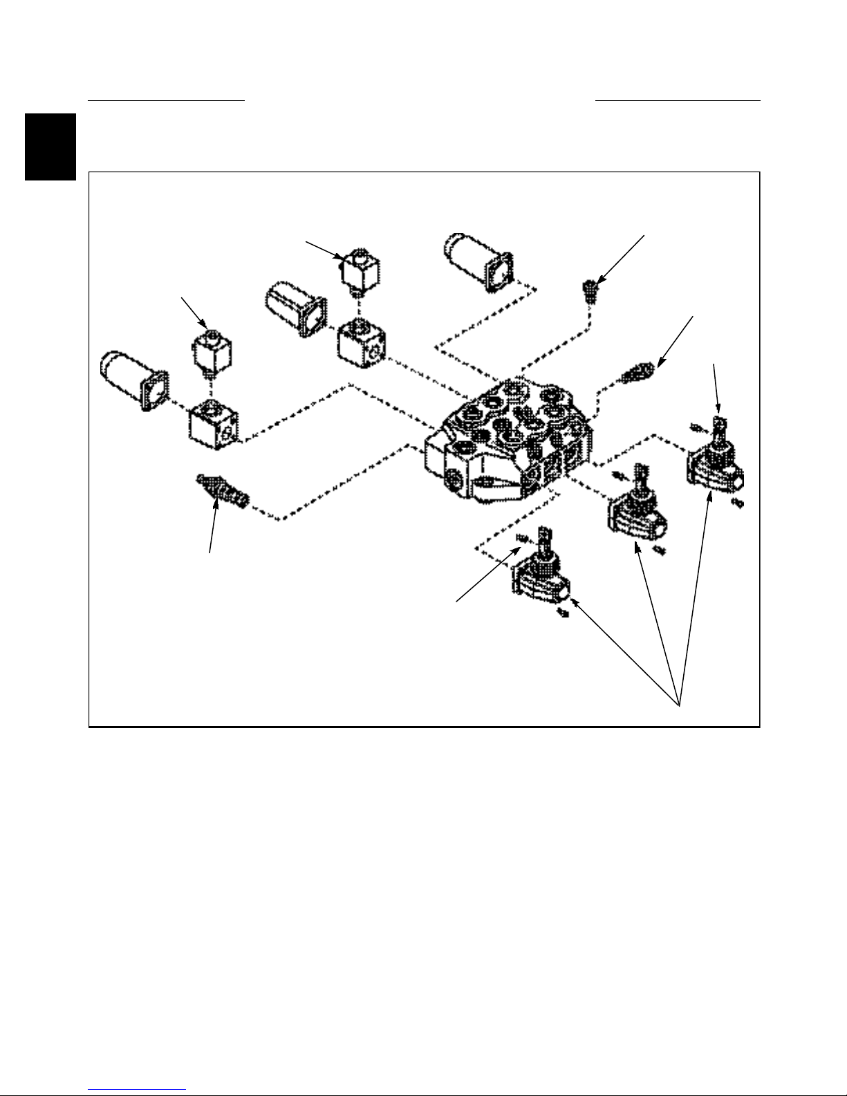
CONTROL VALVE 1.3
Control Valve Disassembly (1700)
6
6
5
2
4
3
7
C3303
Diagram Legend
1. Control Box
2. Set Screws
3. Port Relief Valve
4. Check Valve
5. Main Relief Valve
6. Lock Solenoid Coil
7. Bar
1
1-18
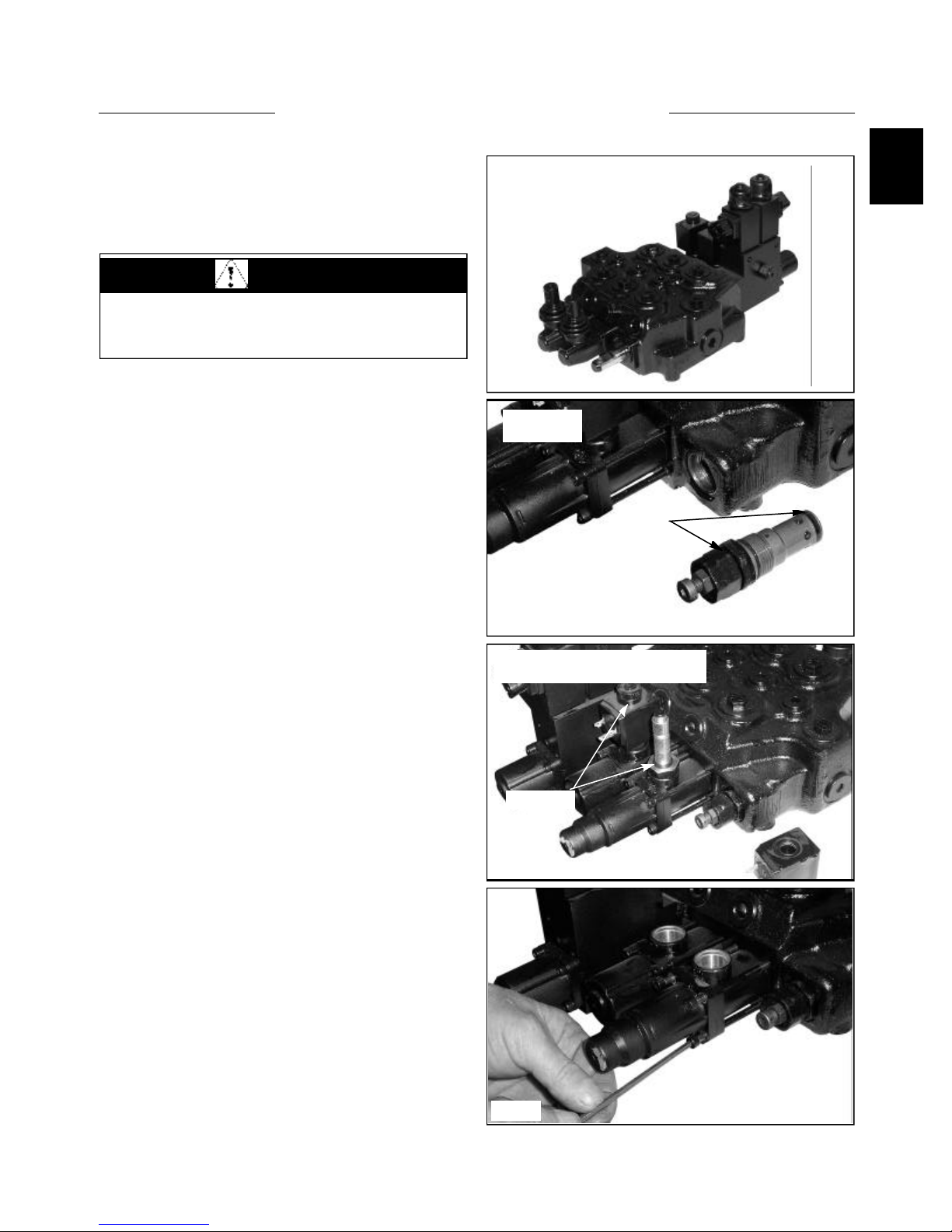
CONTROL VALVE 1.3
1
Disassembly / Repair (175)
Before disassembling the hydraulic control valve, clean
the body with a suitable solvent and dry with compressed
air. (fig. C3696)
WARNING
To avoid eye injury, use safety goggles when
cleaning with compressed air.
Ensure all openings are plugged to prevent solvents and
dirt from contaminating the control valve assembly.
1. Remove the pressure relief valve. Discard the Orings. (fig. C3698)
Control Valve
C3696
Removing the
Relief Valve
O Rings
C3698
2. Remove the solenoid coils and locking pin from the
valve lock block. (fig. C3699) There are 2 O-ring seals
located on either side of the solenoid coils.
3 Remove the spring return detent kit and spring center
cap locks. (fig. C3704, C3706)
Removing the solenoid coils from the
spool locks.
O Ring seal
C3699
C3704
1-19
CONTROL VALVE 1.3
Disassembly / Repair 175
(cont’d)
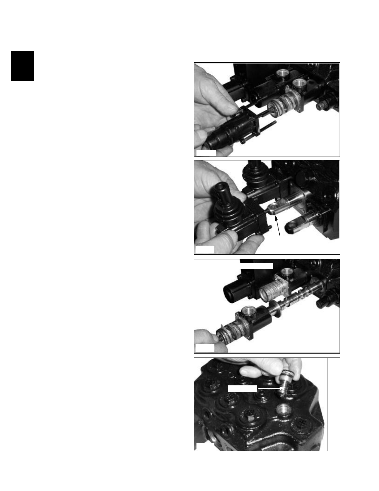
4 Remove the control box from the spool linkage end.
(fig. C3709) The box needs to be tilted upward towards
the valve to release the hardened ball from the hole in the
spool end, and then pull away from the valve.
C3706
5 Pull out the spool. (fig. C3713) As you pull out the
spool, note it’s smooth action as it comes out of the valve
body. The spool should move freely and smoothly in the
bore of the valve body. Check the control valve spool and
bore for scuff marks or abnormal wear. Replace the spool
and or control valve if signs of wear are present.
6 Remove the check valves from control valve body.
(fig. C3717) They are located between the ports of each
section. Check the seat and poppet of the valve body and
check valve. Replace the check valve and or the control
valve if any signs of wear are present.
Spool Linkage
C3709
Removing the spools from the valve.
C3713
Check Valve
C3717
1-20
 Loading...