

Page 1

T105
PUBLICATION NO. 053678
S/N LC002180-LC002185
S/N LC002192-Onward
Owner’s
and
Operator’s
Manual
Skid Steer Loader
Page 2

THOMAS EQUIPMENT LIABILITY WARRANTY
THE WARRANTY IS THE ONLY OBLIGATION OF THOMAS OR A THOMAS DEALER
TO THE PURCHASER OR ANYONE ELSE CONCERNING A PRODUCT, ITS SERVICE,
ITS USE OR PERFORMANCE OR ITS LOSS OF USE OR FAILURE TO PERFORM.
NEITHER
THOMAS NOR A THOMAS DEALER HAVE MADE AND NEITHER WILL
MAKE ANY OTHER EXPRESSED OR IMPLIED REPRESENTATION, WARRANTY OR
AGREEMENT
CONCERNING A PRODUCT. NEITHER THOMAS NOR A THOMAS
DEALER HAVE MADE OR
WILL MAKE ANY REPRESENTATION, WARRANTY OR
AGREEMENT
CONCERNING A
PRODUCTS MERCHANTABILITY OR OTHER
QUALITY, ITS SUITABILITY FOR PURCHASER’S PURPOSE (EVEN IF A PURCHASER
HAS INFORMED THOMAS OR A THOMAS DEALER OF THAT PURPOSE), ITS
DURABILITY, PERFORMANCE OR OTHER CONDITION.
EVEN IF THOMAS OR A THOMAS DEALER WAS ADVISE OF THE POSSIBILITY OF
SUCH LOSS, NEITHER THOMAS NOR A THOMAS DEALER WILL BE LIABLE TO
PURCHASER OR ANYONE ELSE FOR ANY INDIRECT, INCIDENTAL CONSEQUENTIAL,
PUNITIVE, ECONOMIC, COMMERCIAL, OR SPECIAL LOSS WHICH IS IN ANY WAY
ASSOCIATED WITH A PRODUCT. THIS INCLUDES ANY LOSS OF USE OR NONPERFORMANCE OF A PRODUCT, ANY REPLACEMENT RENTAL OR ACQUISITION
COST, ANY LOSS OF REVENUE OR PROFITS, ANY FAILURE TO REALIZE EXPECTED
SAVINGS, ANY INTEREST COSTS, ANY IMPAIRMENT OF OTHER GOODS, ANY
INCONVENIENCE OR ANY LIABILITY OF PURCHASER TO ANY OTHER PERSON.
PURCHASER MAY NOT ATTEMPT TO ENLARGE ITS RIGHTS UNDER THE
WARRANTY BY MAKING A CLAIM FOR INDEMNITY, FOR BREACH OF CONTRACT,
FOR BREACH OF COLLATERAL WARRANTY, FOR A TORT (INCLUDING NEGLIGENCE,
MISREPRESENTATION OR STRICT LIABILITY) OR BY CLAIMING ANY OTHER CAUSE
OF ACTION.
THE WARRANTY IS A CONDITION OF SALE OF THE PRODUCT TO PURCHASER
AND WILL THEREFORE APPLY EVEN IF PURCHASER ALLEGES THAT THERE IS A
TOTAL FAILURE OF THE PRODUCT.
N.B. Read and practice your Thomas operating and servicing instructions. Failure to do this may
void your warranty.
PUBLICATION NO. 053678
Page 3

3
INDEX
1. SAFETY PRECAUTIONS
2. CONTROLS
2. 1 Instrument Panel
2. 2 Seat and Seat Belt
2. 3 Seat Bar
2. 4 Parking Brake
2. 5 Throttle Control
2. 6 Lift Arm Supports
2. 7 Steering Controls
2. 8 Hand Controls
2. 9 Electrical Solenoid Auxiliary
2. 10 Foot Pedals
2. 11 Quick-Tach
2. 12 Electrical Panel
3. OPERATION
3. 1 Starting Instructions
3. 2 Operating Procedure
3. 3 Filling From a Pile
3. 4 Digging with a Bucket
3. 5 Leveling and Backfilling
3. 6 Auxiliary Hydraulics
3. 7 Lifting
3. 8 Towing
3. 9 Securing and Transporting
3. 10 Battery Maintenance and Boosting
3. 11 Lower Lift Arms
4. MAINTENANCE
4. 1 Preventative Maintenance Service Schedule
4. 2 Daily Service Checks
4. 3 50 Hour Service Check
4. 4 Service Access
4. 5 Final Drive Maintenance
4. 6 Hydraulic / Hydrostatic System Maintenance
4. 7 Engine Maintenance
4. 8 Air Cleaner Maintenance
4. 9 Electrical System
4. 10 Tire Maintenance
4. 11 Trouble Shooting
4. 12 Hydraulic / Hydrostatic Circuit
4. 13 Special Tools
5. SPECIFICATIONS
5. 1 Loader Specifications
5. 2 Torque Specifications
5. 3 Sound Power Level
5. 4 Decals, Warning
6. ATTACHMENTS AND BUCKETS
6. 1 Thomas Approved Buckets and Attachments
Page 4
This warning indicates
hazards or unsafe
practices which COULD
result in minor personal
injury or product or
property damage.
CAUTION
This warning indicates
hazards or unsafe
practices which COULD
result in severe personal
injury or death.
WARNING
This warning indicates an
immediate hazard which
WILL result in severe
personal injury or death.
DANGER
Instructions are necessary
before operating or
servicing this machine.
Read the operators
manual and service
decals on the loader.
Follow warnings and
instructions in this
manual when making
repairs, adjustments or
servicing. Check for
correct operation after
adjustments and repairs.
IMPORTANT
This notice shows
important procedures
which must be followed
to prevent damage to the
loader or attachment.
IMPORTANT
4
FOREWORD
This book has been written to give the Owner / Operator necessary operating
servicing and preventative maintenance instructions on the loader.
Read this manual completely and know the loader before operating or servicing it.
Do not do any service procedures that are not in the Operator’s manual.
Only service personnel that have had training in the service of this loader can do these
service procedures.
Reference Information
Write the correct information for your loaders in the spaces below. Always use these
numbers when referring to your loader.
Model No.
Serial No.
Dealer Name
Address
Phone
Throughout this manual the terms DANGER, WARNING and CAUTION are used to
indicate the degree of hazard in terms of personal safety. These words will be used in
conjunction with the Safety - Alert symbol, a triangle with an exclamation mark.
Throughout this manual, the term IMPORTANT is used
* To indicate that instructions are necessary before operating or servicing the
loader.
* To show important procedures which must be followed to prevent damage to
the loader or attachment.
Page 5

5
1. Read this manual carefully before using the loader.
Working with unfamiliar equipment can lead to
accidents.
2. Do not allow anyone to ride on the loader with the
operator.
3. Make sure the control locks and the seat bar are
installed and functioning at all times.
4. Never run the engine in a closed building without
adequate ventilation, as the exhaust fumes can cause
death.
5. Always fasten the seat belt around your waist before
starting the engine. Never fasten the seat belt behind
you.
6. Never attempt to start the engine while standing
beside the unit unless as specified in this manual or
under specific service and backhoe operation
procedures. Start the engine only while sitting in the
operator’s seat with the seat belt fastened around
you. Always check to make certain that the seat
cushion is secured to the frame.
7 Keep the operator’s area free of debris.
8. Never enter or leave the loader while the engine is
running. Always lower the lift arms down against
the frame, drop the attachment down to contact the
ground, set the parking brake and shut off the
engine prior to leaving the loader.
9. If the unit is equipped with a cab enclosure kit
always close the door prior to operating the loader
lift arms.
10. Do not operate the loader unless all safety
equipment, shields, seat belt, seat bar, hydraulic
controls, parking brake, operator guard, and lift arm
supports are working properly, as well as all safety
and instruction decals are in place.
OPERATING THE LOADER
1. Always drive the loader at speeds compatible with
safety, especially when operating over rough
ground, crossing ditches or when turning.
2. Avoid jerky turns, starts, stops, or reverses.
3. Use care when operating on steep grades to
maintain proper stability.
4. Do not turn the loader while the lift arms are in the
raised position.
5. Be careful when driving through door openings or
under overhead objects. Always make sure there is
sufficient clearance for the operator’s guard.
6. When travelling on public roads, know the local
rules and regulations and make sure your loader is
equipped with the proper safety equipment.
7. Always be sure of water, gas, sewage and electrical
line locations before you start to dig.
8. Watch out for overhead and underground highvoltage electrical lines when operating the loader.
9. Always park the loader on level ground where
possible. If the loader is to be parked on an incline,
always lower the attachment so it contacts the
ground, set the parking brake and block the wheels.
10. Do not leave the loader when it is in motion.
11. Do not dismount from the loader and leave the
loader lift arms raised, unless following specific
service procedures. Always lower the lift arms down
against the frame and drop the attachment down to
contact the ground.
12. Always be watchful of bystanders when operating
the loader.
13. Always carry the attachment low for maximum
stability and visibility.
14. Exercise extreme caution when operating the loader
with a raised attachment.
15. Never attempt to lift loads in excess of loader
capacity.
16. Check that the foot pedals are locked before getting
out of the operator’s seat.
MAINTENANCE
1. Stop the engine before performing any service on
the loader.
2. Never refuel the loader while smoking or with the
engine hot or running.
3. Replace all missing, illegible or damaged safety and
warning decals. See section 5.4 for list.
4. Do not modify or alter, or permit anyone to modify
or alter this loader or any of its components or any
loader function.
5. Do not bypass the safety system. Consult your
Thomas
Equipment Dealer if your safety controls are
malfunctioning. Use jumper cables only in
recommended manner. See section 3.10
6. Do not make mechanical adjustments while the
loader is in motion or when the engine is running.
However, if minor engine adjustments must be
made, securely block the loader with the wheels
clear of the ground, and use extreme caution.
7. Do not attempt to repair or tighten hydraulic hoses
when the system is under pressure, when the engine
is running or when the lift arms are raised.
8. Do not get under the attachment or lift arms or
reach through the lift arms when they are raised.
9. Never attach the chains or ropes to the operator’s
guard for pulling purposes, as the loader can tip
over.
1...SAFETY PRECAUTIONS
The following precautions are suggested to help prevent accidents.
A careful operator is the best operator. Most accidents can be avoided by observing certain precautions. Read and take the
following precautions before operating this loader to help prevent accidents. Equipment should be operated only by those
who are responsible and instructed to do so.
Page 6
10. Whenever servicing or replacing pins in cylinder
ends, buckets,
etc., always use a brass drift and a
hammer. Failure to do so could result in injury from
flying metal fragments.
11. Cooling system operates under pressure which is
controlled by the radiator cap. It is dangerous to
remove the cap while system is hot. Always turn cap
slowly to the first stop and allow the pressure to
escape before removing the cap entirely.
12. Keep the operator and foot pedal areas free from
debris.
13. For lifting and towing instructions, refer to
sections 3. 7 and 3. 8 of this manual.
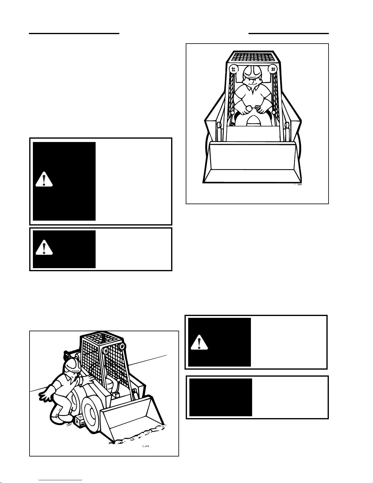
START SAFELY
1. Sit in the operator’s seat and adjust it so you can operate
all of the controls properly.
2. Adjust the seat and fasten the seat belt. Cycle the
controls to make sure they are in the locked or neutral
position. Lower the seat bar.
3. Know the exact starting procedure for your machine.
See Section 3 for the manufacturer’s instructions for
starting.
6
To avoid personal injury,
lower the lift arms, shut off
the engine, raise the seat bar
and cycle the hydraulics to
ensure they are locked.
Then, unlatch the seat belt
and exit the loader. Do not
enter or exit with the engine
running unless as specified
in this manual or under
specific service and backhoe
operating procedures.
WARNING
This engine is equipped
with glow plugs. Do not
use ether or any high
energy fuels to assist
starting.
IMPORTANT
To prevent personal
injury do not operate the
loader without lowering
the safety bar, fastening
the seat belt and keeping
feet on the control pedals
or cab floor.
WARNING
To prevent personal
injury do not start the
engine unless you are in
the seat with the seat belt
fastened around you.
WARNING
C360
PARK SAFELY
Select level ground whenever possible. If you must park on
a slope or incline, position the machine at right angles to
the slope. Lower the attachment to the ground, engage the
parking brake and block the wheels (C359).
C359
1...SAFETY PRECAUTIONS
Page 7

7
2...CONTROLS
2. 1 Instrument Panel
2. 2 Seat and Seat Belt
2. 3 Seat Bar
2. 4 Parking Brake
2. 5 Throttle Control
2. 6 Lift Arm Supports
2. 7 Steering Controls
2. 8 Hand Controls
2. 9 Electric Solenoid Auxiliary
2. 10 Foot Pedals
2. 11 Quick - Tach
2. 12 Electrical Panel
2...CONTROLS
Page 8
8
2...CONTROLS
1. Lift Arm Supports:
For safety while performing service or maintenance,
the loader is equipped with a lift arm support device.
Refer to section 2.6 for details.
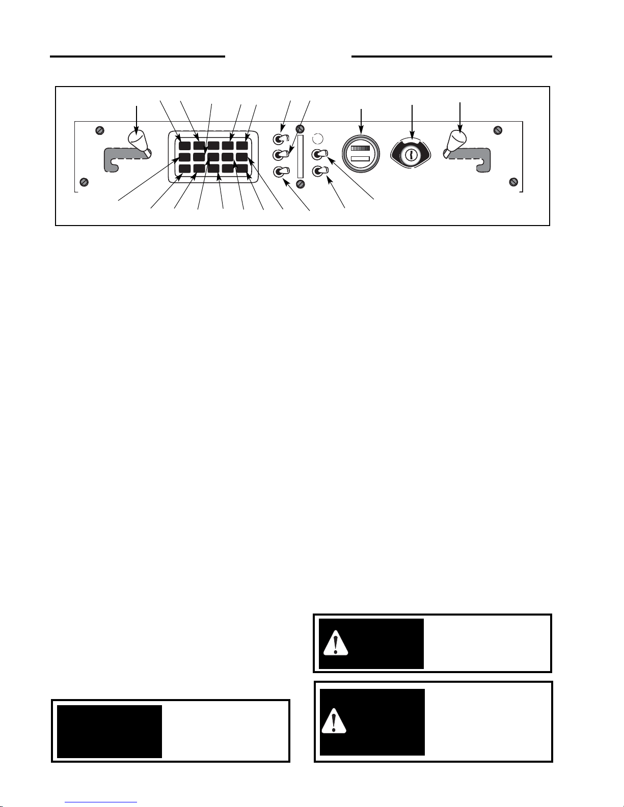
2. Left Signal Indicator Light:
This light will illuminate when the operator uses the
optional left signal (if equipped).
3. Auxiliary Front Indicator Light:
This light will illuminate when the loader auxiliary
hydraulic front switch (if equipped) is turned on.
4. Brake Indicator Light:
The brake light will illuminate when the parking
brake is engaged.
5. Work Light Indicator:
This light will illuminated when the loader
headlights are turned on. This will serve as a
reminder to turn them OFF when the loader is not in
use.
6. Right Signal Indicator Light:
This light will illuminate when the operator uses the
optional right signal (if equipped).
7. Hydraulic Oil Temperature Indicator:
This light will illuminate when the oil temperature
has exceeded recommended levels. Shut off the
engine immediately and determine the cause.
8. Hydraulic Oil Pressure Indicator Light:
This light will illuminate when there is low hydraulic
oil pressure. If this light illuminates, shut off the
engine and determine the cause.
9. Coolant Temperature Indicator Light:
This light will illuminate if there is a rise in engine
temperature. If this occurs, shut off the engine
immediately and determine the cause.
10. Seat Belt Indicator Light:
This light will illuminate when the seat belt is
unfastened.
11. Alternator Indicator Light:
This light will illuminate when the alternator is not
producing sufficient current.
12. Engine Oil Pressure Indicator:
This light will illuminate when the engine loses
lubrication pressure. Shut off the engine immediately
and determine the cause.
13. Pre-heat Indicator Light:
This light will illuminate when the ignition key is
turned counter clockwise to activate the engine glow
plugs.
14. Rotary Beacon Indicator:
This light will illuminate when the optional rotary
beacon (if equipped) is turned on.
15. Hazard Light Switch:
This switch is a toggle switch. Push up to turn the
optional hazard light (if equipped) on.
16. Rotary Beacon Light Switch:
This switch is a toggle switch. Push up to turn the
optional rotary beacon light (if equipped) on.
17. Dipped Beam Light Switch:
This switch is a toggle switch. Push up to turn the
work lights on. The light is located on the front of
the loader.
18. Auxiliary Hydraulics Front Switch:
This switch is a toggle switch. Push up to provide a
continuous flow of hydraulic oil to the quick
couplers when using an attachment.
2.1 INSTRUMENT PANEL
C3066
fig. 2.1
20
3
21
1
15
5
4
2
1
10
9
8
7
18
To prevent personal
injury never add fuel to
the loader when the
engine is running or is
hot. NO SMOKING!
WARNING
This engine is equipped
with glow plugs. Do not
use ether or any high
energy fuels to assist
starting.
IMPORTANT
To prevent personal
injury do not start the
engine unless you are in
the seat with the seat belt
fastened around you.
WARNING
19
16
17
12
6
13
14
11
Page 9
19. Work Light Switch:
This switch is a toggle switch. Push up to turn the
optional work light (if equipped) on. The light is
located on the back of the loader.
20. Fuel Gauge/Hour Meter:
The fuel gauge indicates the quantity of fuel
remaining in the fuel tank. The hour meter records
the number of engine operating hours and has a
total of 9999.9 hours.
21. Ignition Switch:
The ignition switch is a four (4) position switch:
‘OFF’, ‘PRE-HEAT’, ‘RUN’ and ‘START’. Turn
the key counter clockwise to engage engine ‘PREHEAT’. Turn the key clockwise to the ‘START’
position, this engages the starter. The key will be in
the ‘RUN’ position when released. Turn the key to
‘OFF’ to shut off the engine and remove the key.
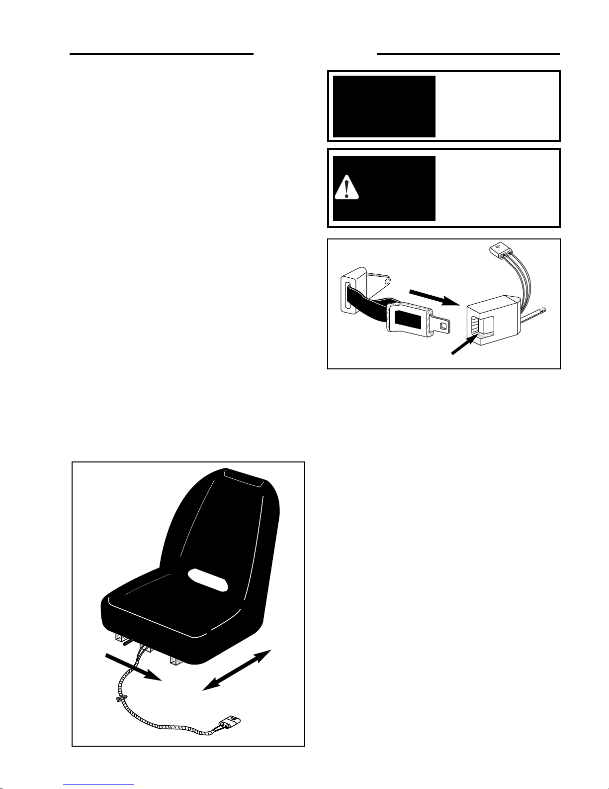
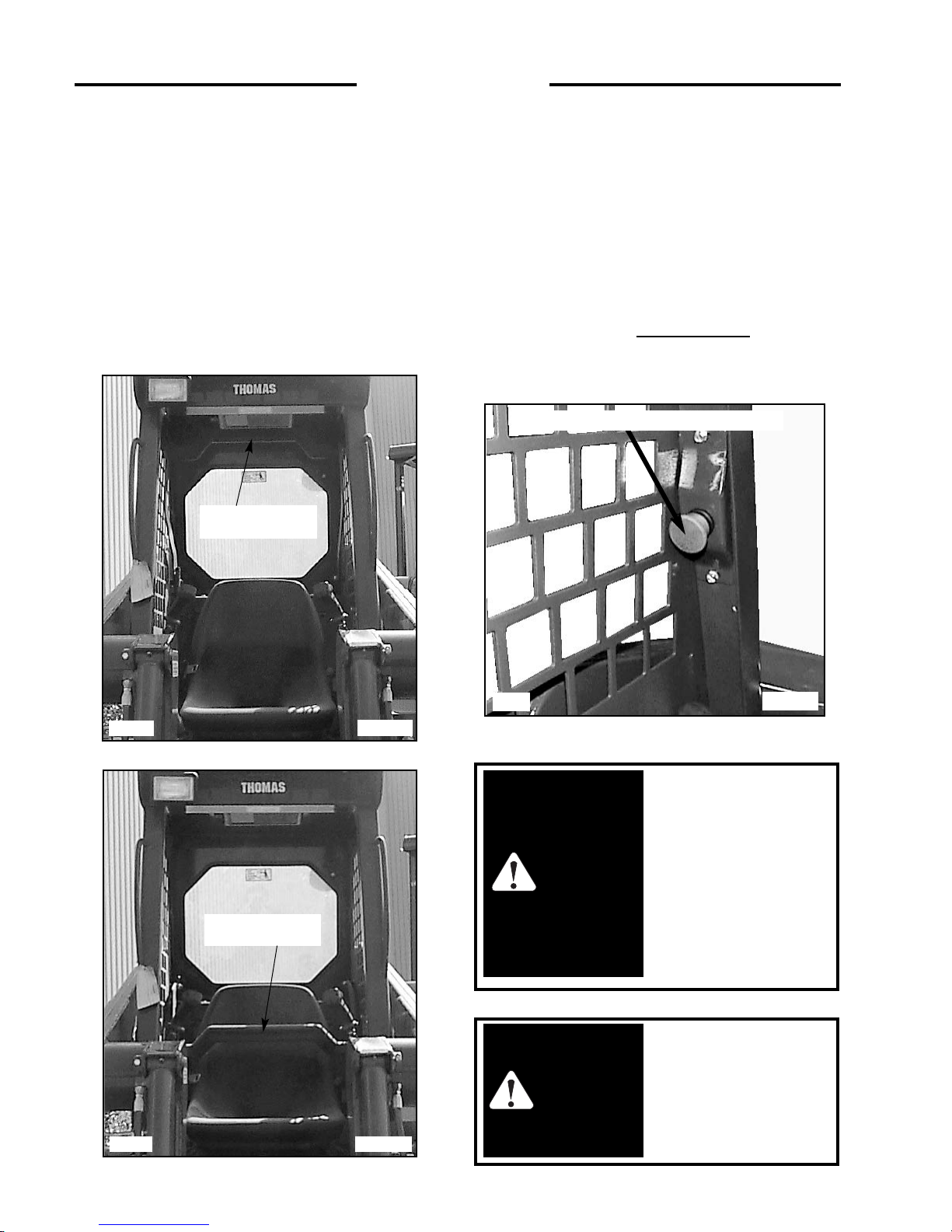
2. 2 SEAT AND SEAT BELT
The loader is equipped with a deluxe seat. The seat can
be adjusted forward or back for operator comfort. (Fig.
2.2A).
For your safety the loader is equipped with a seat belt.
Before starting the loader adjust and fasten the beat belt
(Fig. 2.2B) around you. The seat and seat belt also have
integrated safety lock switches whereby the operator
must be seated in the seat with the belt securely fastened
before the loader can be operated.
9
2...CONTROLS
fig. 2.2B
C2698
fig. 2.2A
C2699
Fully retract the lift arm
supports before raising
or lowering lift arms.
IMPORTANT
To prevent personal
injury do not start the
engine unless you are in
the seat with the seat belt
fastened around you.
WARNING
Seat Adjust
Seat Belt Mechanism
Release
Page 10
10
2. 3 SEAT BAR
For operator protection the loader is equipped with a seat
bar.
To raise the seat bar, lift up on the bar (Fig. 2. 3A). In the
up position, the seat bar activates the park brake.
Before exiting the loader always check hand control
levers by cycling them to be sure they are in the neutral
position. The loader must be started with the operator
seated in the loader and the seat bar in the up
position.When down, the seat bar releases the park brake
(Fig. 2. 3C).
2. 4 PARKING BRAKE
The loader is equipped with park brakes, located inside the
torque motor. The brakes are activated and de-activated by
the seat bar, via charge pressure. When the seat bar is in
the up position, the brake is activated (Fig. 2.3A). When
the seat bar is in the down position, the brake is off (Fig.
2.3C).
The loader has a parking brake indication light to warn that
the brake is engaged. When the seat bar is in the down
position, activation of the emergency brake
can be carried
out by pushing on the button (optional), located on the
ROPS in front of the Left Control Handle.
2...CONTROLS
To avoid personal injury,
lower the lift arms, shut off
the engine, raise the seat bar
and cycle the hydraulics to
ensure they are locked. Then,
unlatch the seat belt and exit
the loader. Do not enter or
exit with the engine running
unless as specified in this
manual or under specific
service and backhoe
operating procedures.
WARNING
C-689
fig. 2. 3C
To avoid personal injury
do not enter or exit the
loader with the engine
running unless as
specified in this manual
or under service
procedures and backhoe
operation.
WARNING
C999
fig 2. 4c
Optional Emergency Brake Button
Seat Bar DOWN
(Parking Brake Off)
C3163
fig. 2.3A
Seat Bar UP
(Parking Brake On)
Page 11
11
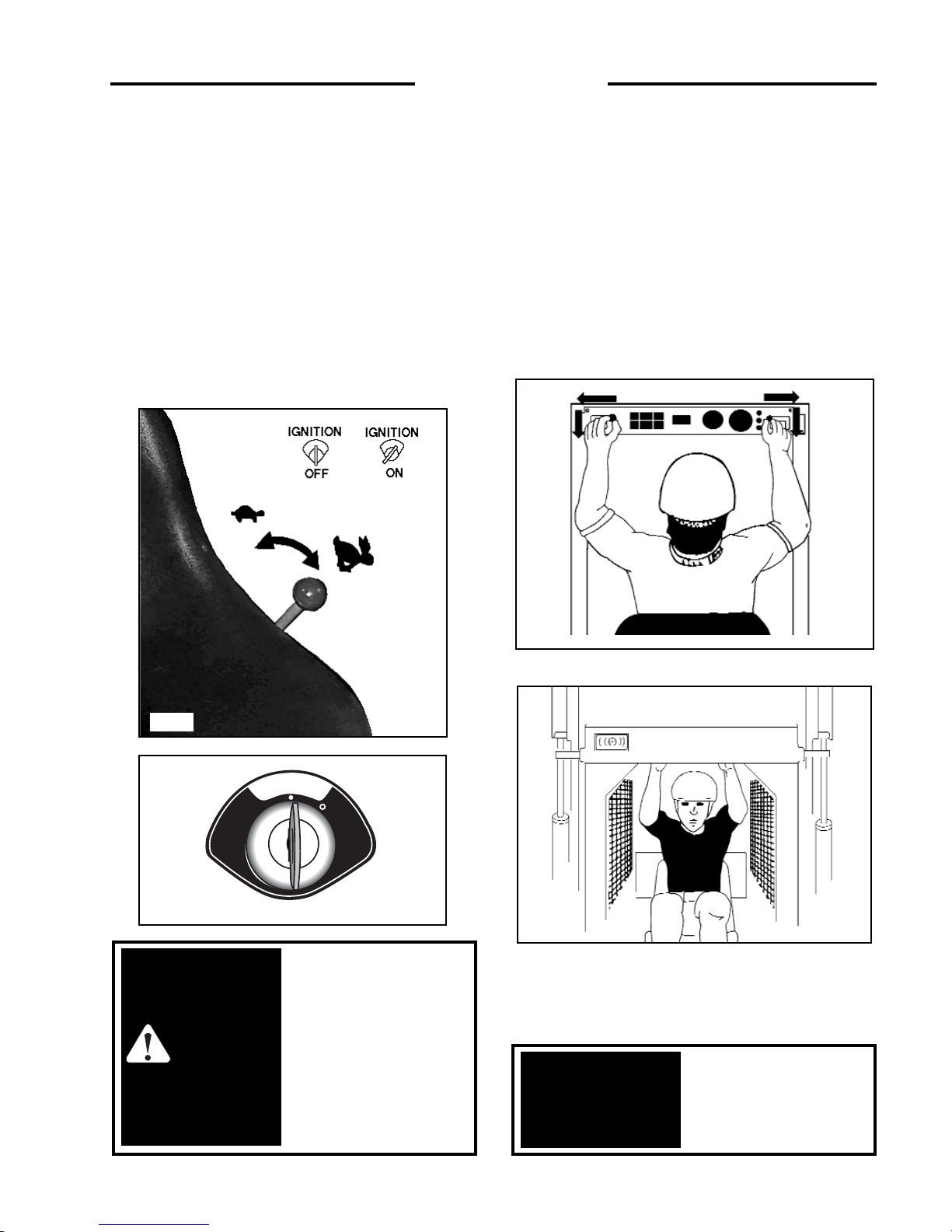
2. 5 THROTTLE CONTROL
The diesel engine throttle control, is the lever located on
the left hand side of the loader next to the steering control
lever (Fig. 2. 5A) Engine start and stop are controlled
electrically by the ignition key. (FIG. 2. 5B)
Before shutting off the engine, return the throttle control to
idle position and allow the engine to cool at least 2
minutes. Pushing the lever full forward increases the
engine speed to maximum high idle. Pulling the lever back
decreases the engine RPM.
The engine should always be operated at full speed and the
loader travel speed controlled with the steering control
levers. (See section 2. 7)
2. 6 LIFT ARM SUPPORTS
For safety while performing regular service or
maintenance work, the loader is equipped with lift arm
supports.
The lift arm supports, when extended, prevent the lift arms
from dropping if hydraulic pressure is relieved or the foot
control pedals are accidentally cycled.
To operate the lift arm supports, first remove any bucket or
attachment from the quick-tach; raise the lift arms to full
height and shut OFF the engine. Raise the lift arm support
handles (Fig. 2. 6A) up and push out toward lift arms to
extend the lift arm supports. (Fig. 2. 6B)
Fully retract the lift arm
supports before raising
or lowering lift arms.
IMPORTANT
C -729
fig. 2. 6A
C-839
fig. 2. 5A
2...CONTROLS
To avoid personal injury,
lower the lift arms, shut off
the engine, raise the seat bar
and cycle the hydraulics to
ensure they are locked. Then,
unlatch the seat belt and exit
the loader. Do not enter or
exit with the engine running
unless as specified in this
manual or under specific
service and backhoe
operating procedures.
WARNING
C3158
fig .2. 5B
C730
fig. 2. 6B
T
A
E
H
E
C
R
E
P
R
P
S
W
R
E
I
T
T
C
R
A
H
T
S
A
T
C
N
T
O
C
E
G
A
F
F
U
A
H
S
T
A
D
R
E
T
M
A
R
R
A
G
E
Page 12
12
2...CONTROLS
C2701 fig. 2. 7A
To avoid personal injury
do not start the engine
unless you are in the seat
with the seat belt
fastened around you
unless specified in this
manual or under specific
service and backhoe
operating procedures.
WARNING
To avoid personal injury
always carry the load
low.
WARNING
Faster - Slow - N - Slow - Faster
C696
fig. 2. 7B
FORWARD
C697
REVERSE
C698
LEFT TURN
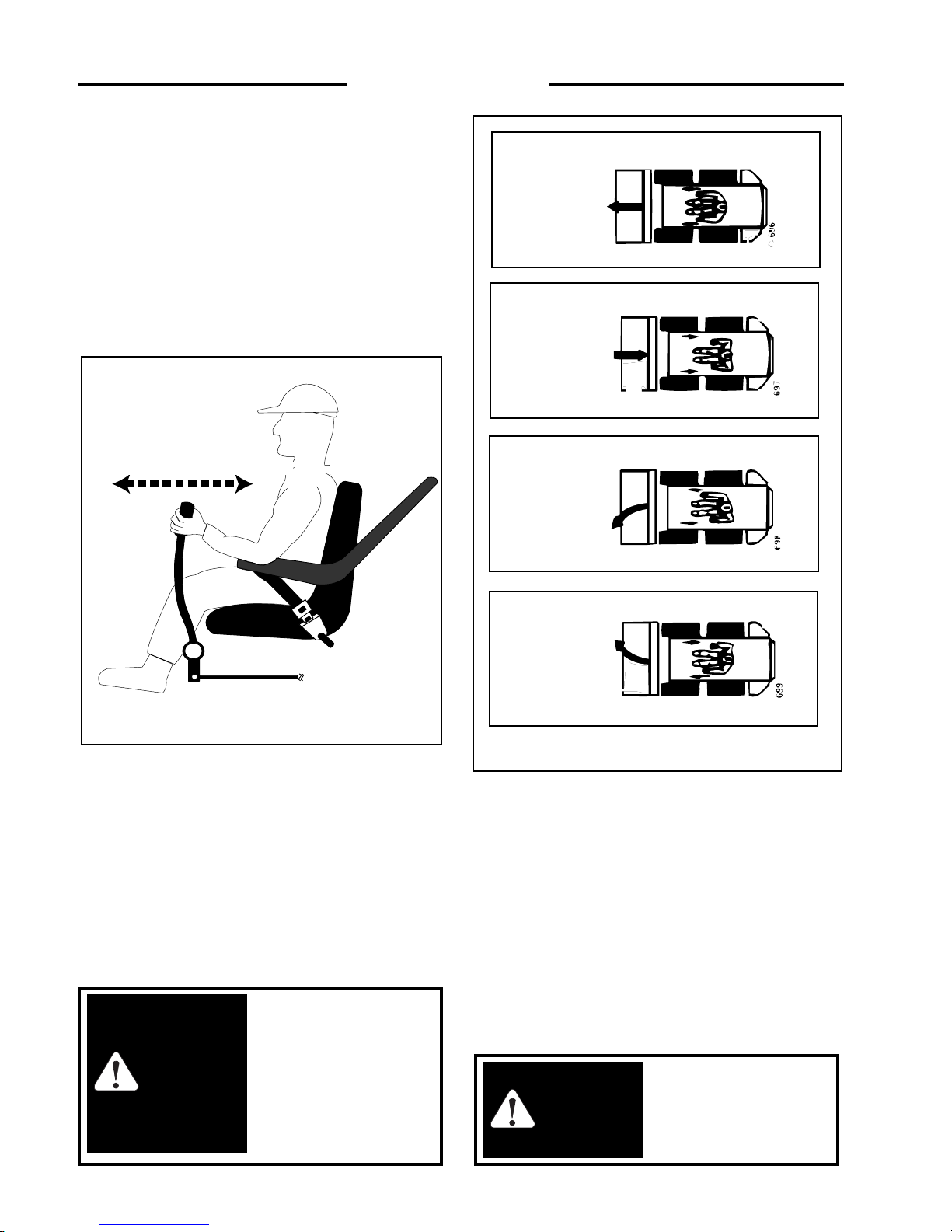
2. 7 STEERING CONTROLS
The two steering levers control speed, direction and
turning the loader. The R.H. lever controls the wheels on
the R.H. side of the loader and the L.H. lever controls the
wheels on the left hand side of the loader. The loader speed
is controlled by the amount each lever is moved from
centre or neutral position. (Fig. 2. 7A) The further away
from neutral the faster the travel speed. For maximum
power and slow travel speed move the control levers only
a small amount. To drive the loader forward in a straight
line, move both control levers forward the same amount.
(Fig. 2. 7B)
To drive the loader in reverse in a straight line, move both
control levers back the same amount (Fig. 2. 7B). The
loader is turned by moving one lever further forward than
the other. To turn right move the left lever further than the
right lever, to turn left move the right lever further than the
left lever. For the loader to turn or “skid-steer” within its
own length, one lever is moved forward and the other
back. This causes the wheels on one side to turn forward
and the wheels on the other side to reverse turning the
loader. (Fig. 2. 7B)
2.8 HAND CONTROLS (OPTIONAL)
Hand controls to operate the loaders lift arm and bucket
hydraulic system as well as the loaders travel speed and
direction are available. Refer to section 2. 7 for instruction
on steering controls.
C699
RIGHT TURN
Faster - Slow - Neutral - Slow - Faster
Page 13
13
2...CONTROLS
LIFT ARM and BUCKET CONTROLS:
The right hand lever controls the bucket tilt cylinders (Fig. 2.
8A). Moving the left hand control lever to the left will cause
the lift cylinders to extend, raising the loaders lift arms.
Moving the control lever to the right causes the lift cylinders to
retract, lowering the lift arms. Moving the control lever to
extreme right will place the lift arms in float position. This
allows the bucket to follow the contour of the ground as the
loader moves backward.
When the control levers are released they will automatically
return to the neutral position stopping all hydraulic movement
and travel speed. Before exiting the loader, shut off the engine
and lower the lift arms completely down to the frame and
ground the attachment. Raise the seat bar to the locked
position. Move both levers to the left and right to ensure the
hydraulic controls are locked before you get out of the loader.
AUXILIARY HYDRAULICS:
The foot pedal is used to engage the loaders auxiliary hydraulic
circuit to power an attachment such as a post hole auger.
Pressing on the toe of the pedal provides hydraulic flow to the
female quick - connect coupling located at the front of the lift
arms. Firm pressure on the toe of the pedal will lock it into
detent position providing a continuous flow of hydraulic oil to
the attachment.
Pressing on the heel of the pedal provides hydraulic flow to the
quick-connect coupling reversing the flow of hydraulic oil. If
not locked in detent position, releasing the pedal will cause it
to return to the neutral position stopping all hydraulic flow.
Once the pedal is locked in detent, it can be returned to neutral
by tapping the heel of the pedal.
When the auxiliary hydraulic system is not in use return the
pedal to the neutral position otherwise starting the loader may
be difficult or impossible and damage to the starter motor may
occur.
To prevent personal
injury do not start the
engine unless you are in
the seat with the seat belt
fastened around you.
WARNING
Return the auxiliary
hydraulic
foot pedal to
neutral position when not
in use.
IMPORTANT
C3165
fig. 2.8A
Reverse
Raise
Lift
Arms
Lower
Forward
Roll Back
Dump
Reverse
Forward
Page 14
14
2. 9
ELECTRICAL SOLENOID AUXILIARY
(OPTIONAL)
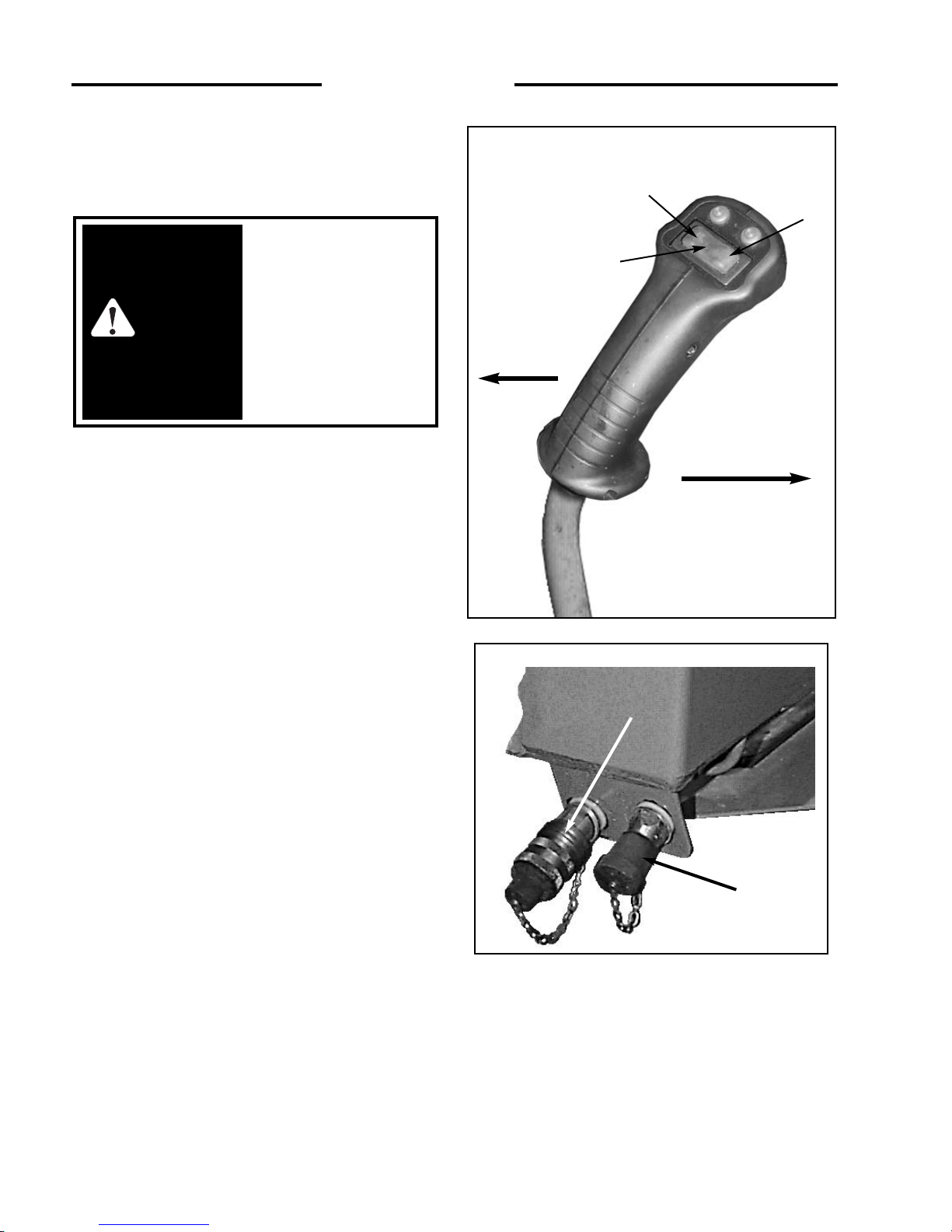
A switch located in the L.H. steering control lever (Fig. 2. 9A)
is used to engage the loaders auxiliary hydraulic circuit to
power attachments such as post hole augers, sweepers etc.
CONTROLS:
By pressing and holding the switch in position 1 (Fig. 2. 9A)
provides hydraulic flow to the female quick connect coupling
located at the front of the lift arms (Fig. 2. 9B). Releasing the
switch returns the auxiliary hydraulic circuit to neutral,
stopping hydraulic flow.
By pressing and holding the switch in position 2 (Fig. 2. 9A)
provides hydraulic flow to the male quick connect coupling
located at the front of the lift arms (Fig. 2. 9B). Releasing the
switch returns the auxiliary hydraulic circuit to neutral,
stopping hydraulic flow.
For continuous flow to the auxiliary hydraulic circuit, a toggle
switch is located on the Instrument Panel. Placing the switch in
the ON position provides continuous hydraulic flow to the
female quick connect coupling located at the front of the lift
arms (Fig. 2. 9B). To stop hydraulic flow to the auxiliary
hydraulic circuit, return the switch to the “OFF” position.
When the switch on the instrument panel is in the ON position,
the switch located in the L.H. control lever is not operable.
NOTE: The optional left hand control lever auxiliary control
switch operates a horn, if equipped.
To avoid personal injury,
lower the lift arms, shut off the
engine, raise the seat bar and
cycle the hydraulics to ensure
they are locked. Then, unlatch
the seat belt and exit the
loader. Do not enter or exit
with the engine running unless
as specified in this manual or
under specific service and
backhoe operating procedures.
WARNING
fig. 2. 9A
C3166
Fig. 2. 9B
C - 641
MALE QUICK CONNECT
FEMALE QUICK CONNECT
2...CONTROLS
Control Lever Switch (L.H.)
Seat side
ROPS side
2
1
NEUTRAL
Page 15
15
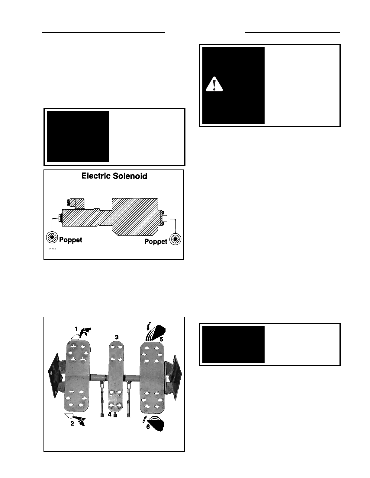
2...CONTROLS
When the auxiliary circuit is not in use and before starting the
loader, ensure the switch located in the. instrument panel is in
the off position, otherwise starting the loader may be difficult
or impossible and damage to the starter may occur. If for any
reason the loader stops or loses current when the electric
solenoid is engaged, it can be disengaged by simply turning off
the switch located in the upper panel, or by depressing the
poppet located at either end of the control valve (Fig. 2.9B).
2.10 FOOT PEDALS
Operation of the lift cylinders, bucket tilt cylinders and
auxiliary hydraulic circuit are controlled by foot pedals
(Fig. 2. 10) connected to a hydraulic control valve. The
hydraulic control valve is a series type valve which allows
simultaneous use of both the lift and bucket tilt circuits.
Lift –
The L.H. pedal is the lift control (Fig. 2. 10). To raise
the lift arms press on the heel (2) of the pedal. To lower the lift
arms press on the toe (1) of the pedal. Firm pressure on the toe
(1) of the pedal will lock the lift arms in float position. This
allows the bucket to follow the ground as the loader moves
backward.
Auxiliary Hydraulics –
The center pedal is used to engage
the auxiliary hydraulic circuit to power an attachment such as
a backhoe. Pressing on the toe (3) of the pedal provides
hydraulic pressure to the female quick - connect coupling
located at the front of the lift arms. Firm pressure on the toe (3)
of the pedal places the valve in detent position providing a
continuous flow of hydraulic oil to the attachment. Pressing on
the heel of the pedal (4) provides hydraulic pressure to the male
quick-connect coupling reversing the flow of hydraulic oil.
When the auxiliary circuit is not in use return the foot pedal to
neutral position otherwise starting the loader may be difficult
or impossible and damage to the starter may occur.
Bucket Tilt –
The R.H. pedal is the bucket tilt (dump)
control. Pressing on the toe (5) of the pedal will dump the
bucket. Pressing on the heel (6) of the pedal will roll the bucket
back.
To avoid personal injury,
lower the lift arms, shut off
the engine, raise the seat bar
and cycle the hydraulics to
ensure they are locked. Then,
unlatch the seat belt and exit
the loader. Do not enter or
exit with the engine running
unless as specified in this
manual or under specific
service and backhoe
operating procedures.
WARNING
Return auxiliary
hydraulic foot pedal to
neutral position when not
in use.
IMPORTANT
C - 318
fig. 2. 10
C - 702
fig. 2. 9B
Return the auxiliary control
switch to OFF when not in
use otherwise starting may
be impossible and damage
to the starter may occur.
Return toggle switch to
neutral
.
IMPORTANT
Page 16
16
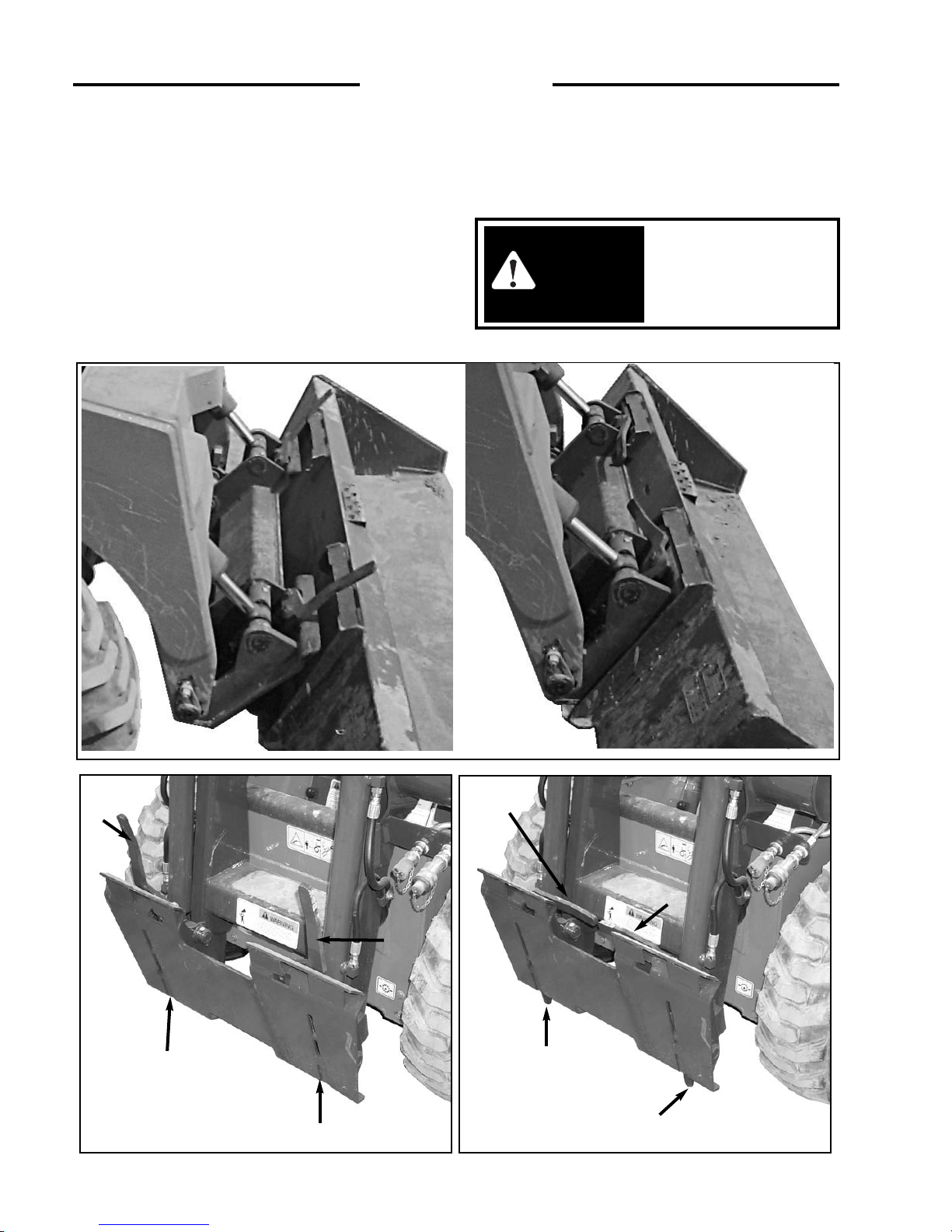
2. 11 QUICK - TACH
The loader is available with a Thomas Quick - Tach. The
Thomas Quick - Tach is designed to fit Thomas approved
attachments.
The quick - tach, which is standard equipment, allows
changing from one attachment to another quickly without
having to remove bolt or pins.
To operate, simply lift the
two over - centre locking levers to disengage the lock pins
(Fig. 2. 11B). Tilt the quick-tach frame forward (Fig. 2. 11A)
with the bucket tilt cylinders and drive into the attachment.
Retract the bucket tilt cylinders which will line up the
bottom of the attachment with the quick-tach lock pins. Shut
off the engine. Push the locking levers down (4) (Fig. 2.
11B) extending the lock pins (5) through the attachment.
Before operating the attachment check that the locking pins
are correctly engaged.
After hook up the
attachment check to be
sure pins and locking
levers are fully engaged.
WARNING
1108 Fig. 2.11A
C-660
C-661
Fig. 2.11A
Fig. 2. 11A
C3069
C3070
fig. 2. 11B
5
4
5
fig. 2. 11B
2...CONTROLS
4
5
4
5
4
Page 17
17
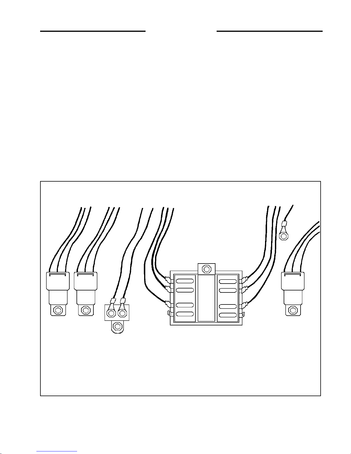
2. 12 ELECTRICAL PANEL
The loader is equipped with a 12 volt, negative ground
electrical system. The fuse and relay panel is located in the
engine compartment just in front of the battery box. The
panel consist of the following:
1. Glow Plug Relay
2. Starter Relay
3. Fan Relay
4 Main Electrical Circuit Breaker
FUSE PANEL
5. Valve Locks / Park Brake
6 Fan
7. Electric Fuel Shutoff
8. Spare
9. Horn
10. Solenoid Auxiliary
11. Alternator
12. Spare
STARTER
RELAY
GLOW
PLUG
RELAY
2...CONTROLS
FAN
RELAY
MAIN
ELECTRICAL
CIRCUIT
BREAKER
1
3 2
4
C-897
GROUND
5
9
6
10
7 11
8
12
10
10
10
10
10
10
Page 18

18
3...OPERATION
3. 1 Starting Instructions
A. Pre - Starting Inspection
B. Starting Procedure
C. Shut - Off Procedure
3. 2 Operating Procedure
3. 3 Filling From a Pile
3. 4 Digging With a Bucket
3. 5 Leveling and Backfilling
3. 6 Auxiliary Hydraulics
3. 7 Lifting
3. 8 Towing
3. 9 Securing and Transporting
3. 10 Battery Maintenance and Boosting
3. 11 Lowering Lift Arms
3...OPERATION
Page 19
19
3. 1 STARTING INSTRUCTIONS
A. Pre-Starting Inspection
Before starting the loader complete the
following inspection:
1. Check the hydraulic oil level, engine oil
level, engine coolant level and fuel supply.
2. Check the air filter indicator.
3. Check for fuel, oil and hydraulic leaks.
4. Check lights, battery level and cables.
5. Check tire pressure:
8.50 X 15 30 - 35 P.S.I. (207 - 241 kPa)
10.50 x 15 30 - 35 P.S.I. (207 - 241 kPa)
6. Check wheel nut torque 100 - 110 ft. lbs. (136 - 149
Nm)
7. Lubricate all grease fittings.
8. Check the condition and operation of all safety decals
and equipment – Ensure all shields and safety screens
are in place. If necessary repair or replace before
starting.
For complete daily servicing refer to section 4. 2.
B. Starting Procedure – Diesel
1. Ensure the seat bar is in the UP position and the
steering controls are centered and the hydraulic
controls are locked.
2. Adjust and fasten the seat belt securely around you.
3. Place the throttle control in idle position.
4. Turn the ignition key counter clockwise to activate the
glow plugs. Hold approximately 15 seconds. Both the
alternator and engine oil pressure warning lights
should be on.
5. Turn the key clockwise to start position to engage the
starter. Do not crank the starter for more than 15
seconds. If the engine fails to start turn the key counter
clockwise and pre - heat again.
6. When the engine has started the engine oil pressure
and alternator warning lights should go out. If they
don’t, shut - off the engine immediately and determine
cause. Allow the engine to warm up for five minutes
before operating. When ready to operate, lower the
seat bar and advance the throttle to full on position.
C. Shut-Off Procedure
1. Park the loader on level ground. If it’s necessary to
park on a slope, position the machine at right angles to
the slope.
2. Lower the lift arms and ground the attachment.
3. Return the throttle control to idle position. If the
engine is hot allow it to idle until normal. At least 2
minutes.
4. When the engine is cool, turn the ignition key to the
OFF position and remove the key.
5. Never enter or exit the loader when the engine is
running unless as specified in this manual or under
specific service and backhoe operating procedures.
6. Place the auxiliary foot pedal in neutral position. If the
auxiliary foot pedal is left in detent, restarting the
machine may be impossible. If equipped with an
electric solenoid make sure the switch is in the OFF
position.
7. Raise the seat bar to apply the park brake. Turn the
ignition switch to the OFF position, unfasten the seat
belt, and ensure the pedals are locked by rocking them,
and ensure the steering levers are in neutral.
3...OPERATION
This engine is equipped
with glow plugs. Do not
use ether or any high
energy fuels to assist
starting.
IMPORTANT
WARNING
To avoid personal injury,
lower the lift arms, shut off
the engine, raise the seat bar
and cycle the hydraulics to
ensure they are locked. Then,
unlatch the seat belt and exit
the loader. Do not enter or
exit with the engine running
unless as specified in this
manual or under specific
service and backhoe operating
procedures.
To prevent personal
injury do not operate the
loader without lowering
the safety bar, fastening
the seat belt and keeping
feet on the control pedals
or cab floor.
WARNING
WARNING
To avoid personal injury,
do not start the engine
unless you are in the seat
with the seat belt fastened
around you. Do not enter
or exit with the engine
running unless as specified
in this manual or under
specific service and
backhoe operating
procedures.
Page 20
20
3...OPERATION
Always let the engine
warm completely before
you begin operation each
day.
IMPORTANT
C-705
fig. 3.3A
fig. 3.3B
LH
RH
LH
RH
3. 2 OPERATING PROCEDURES
1. When learning to use the loader operate at a slow rate.
2. Take advantage of the efficient operation of the loader.
Keep the travel distance as short as possible. Keep the
work area small so the cycle time is short.
3. Keep the work area as level as possible.
4. Decrease cycle time by “skid” turning (section 2 .7) rather
than a go backward-go forward turn.
5. Fill the bucket to rated capacity. Turning is easier with a
full load than with a partial load. Keep the loaded bucket
close to the ground when transporting.
6. Tilt the bucket as you raise the lift arms or drive up a
slope. This will prevent material from falling off the back
of the bucket.
7. Do not drive across a slope. Always go up or down a slope
with the heavy end of the loader pointing up towards the
top of the slope.
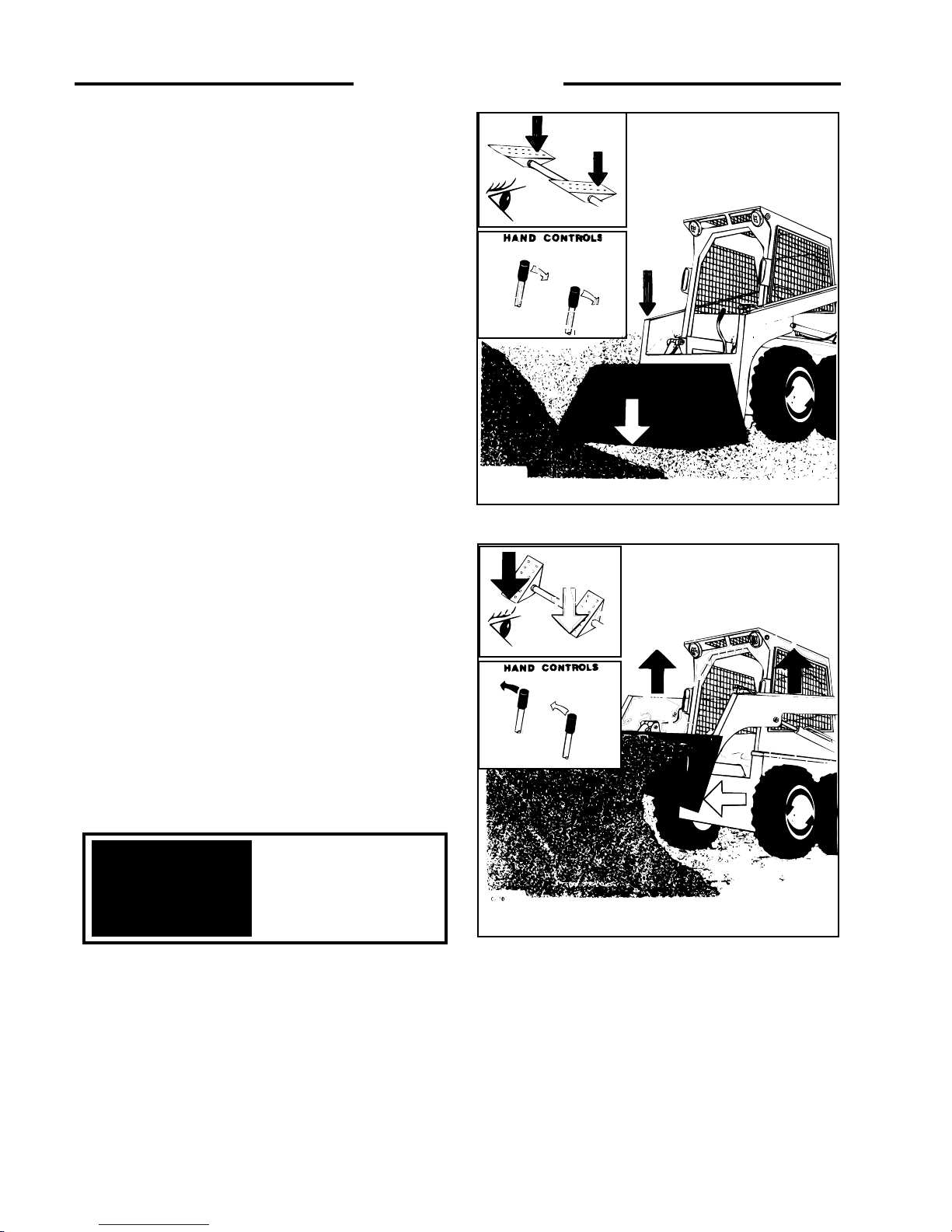
3. 3 FILLING FROM A PILE
Push down on the toe of the lift arm pedal and lower the lift arms
completely down (Fig. 3. 3A). Push the toe of the bucket pedal
and place the cutting edge of the bucket on the ground. For hand
control units, move the L.H. control lever towards you and lower
the lift arms completely down.Move the R.H. control lever away
from you (Fig. 3. 3A) and place the cutting edge of the bucket on
the ground.
Drive the loader forward slowly. As the bucket begins to fill push
on the heel of the bucket pedal to raise the front of the bucket
(Fig. 3. 3B) and push on the heel of the lift arm pedal to raise the
lift arms. When the bucket is full back away from the pile. For
hand control units, move the R.H. control lever towards you to
raise the front of the bucket, and move the L.H. control lever
away from you to raise the lift arms (Fig. 3. 3B). When the bucket
is full back away from the pile.
C-708
C-706
Page 21

To dump the bucket (Fig. 3. 3C) push down on the heel of the
lift arm pedal to raise the lift arms. Push down on the toe of
the bucket pedal small amounts as the lift arms are raising to
stop material from falling off the back of the bucket. When
the bucket is at the correct height for dumping, push on the toe
of the bucket pedal to empty the bucket.
For hand control units, move the L.H. control lever away
from you (Fig. 3. 3C) to raise the lift arms. Move the R.H.
control lever away from you in small amounts as the lift arms
are raising to stop material from falling from the back of the
bucket. When the bucket is at the correct height for dumping,
move the R.H. lever away from you to empty the bucket.
3. 4 DIGGING WITH A BUCKET
Push on the toe of the lift arm pedal and lower the lift arms
completely down. Push on the toe of the bucket pedal and
place the cutting edge of the bucket on the ground (Fig. 3.
4D). Drive the loader forward at a slow rate and continue to
tilt the bucket down until it enters the ground.
Push down on the heel of the bucket pedal (Fig. 3.4E) to
increase traction and keep an even digging depth.
Continue to drive forward until the bucket is full. When
digging in hard ground, it is easier to raise and lower the
bucket cutting edge with the tilt pedal while slowly driving
forward.
When the bucket is full push down on the heel of the bucket
pedal (Fig. 3. 4F) to raise the tip of the bucket.
For hand control units, move the L.H. control lever towards
you to lower the lift arms completely down. Move the R.H.
control lever away from you and place the cutting edge of the
bucket on the ground (Fig. 3. 4D). Drive the loader forward
at a slow rate and continue to tilt the bucket down until it
enters the ground. Move the R.H. control lever towards you
(Fig. 3. 4E) to increase traction and keep an even digging
depth. Continue to drive forward until the bucket is full.
When the bucket is full, move the R.H. control lever towards
you (Fig. 3. 4F) to raise the tip of the bucket.
21
C711
fig. 3.4D
3...OPERATION
To avoid personal injury:
When starting or
operating loader in an
enclosed area make sure
there is enough
ventilation. Exhaust
fumes can kill.
WARNING
To avoid personal injury
always carry the load
low.
WARNING
fig. 3.3C
1055
LH
LH
LH
RH
RH
RH
fig. 3. 4E
C-710
C - 712
C - 714
Page 22

22
3. 5 LEVELING AND BACKFILLING
Spread dirt on uneven ground by pushing on the heel of the lift
arm pedal (Fig. 3.5G) to raise the lift arms and push on the toe
of the bucket pedal to tilt the bucket down as you drive
forward.
For hand control units, spread dirt on uneven ground by
moving the L.H. control lever away from you (Fig. 3. 5G). To
raise the lift arms and move the right hand control lever away
from you to tilt the bucket down as you drive forward.
To level the ground; raise the lift arms and tilt the bucket down
by pressing on the toe of the bucket pedal (Fig. 3.5H). Push
firmly on the toe of the lift arm pedal to lock the lift arms in
float position. The weight of the lift arms and bucket will hold
the bucket on the ground. Drive backward to level material.
To level the ground with a hand control unit, raise the lift arms
and tilt the bucket down by moving the R.H. control lever
away from you. Move the L.H. control lever all of the way
towards you (Fig. 3. 5H) to place the lift arms in the float
position. The weight of the lift arms and the bucket will hold
the bucket on the ground. Drive backwards to level material.
To fill a hole (Fig. 3. 5I) drive the loader slowly with the
bucket low, up to the hole. As the bucket passes the edge of the
hole, push on the toe of the bucket pedal to dump the bucket.
When necessary raise the lift arms to empty the bucket.
On hand control units, as the bucket passes the edge of the
hole, move the R.H. control lever away from you to dump the
bucket. When necessary, raise the lift arms to empty the
bucket.
3...OPERATION
C- 718
C - 716
LH
LH
LH
LH
RH
RH
RH
RH
1059
FIG 3.5G
FIG 3. 5H
FIG 3. 5I
Fig.3. 4F
C-720
C-722
Page 23

23
3. 6 AUXILIARY HYDRAULICS
To operate an attachment such as a grapple fork using the
auxiliary hydraulic circuit, push on the heel of the centre
or auxiliary pedal to open the grapple (Fig. 3. 6J).
To close the grapple (Fig. 3. 6K), push down on the toe of
the auxiliary pedal. The lift arm and the bucket pedals can
be used to raise and tilt the grapple as with a bucket.
To operate an attachment which requires a constant flow of
oil such as a sweeper push down firmly on the toe of the
auxiliary pedal until the pedal locks in detent position.
When the auxiliary circuit is not in use return the auxiliary
pedal to neutral position otherwise starting the loader may
be difficult or impossible.
3. 7 LIFTING
The loader can be equipped with optional features to use in
lifting (for example by crane onto a flatbed trailer or a flat
car), for securing, and for extraction (from mud or snow).
To lift using a crane, first follow the shut-off procedure in
section 3.1C.
Once this is done, attach properly rated cables, chains or
straps to lift points provided (Fig. 3.7). To prevent marking
the operator guard or chafing of the lifting cable, a lifting
frame should be used.
3...OPERATION
Return the auxiliary
control to neutral when
not in use otherwise
starting may be
impossible and damage
to the starter may occur.
Return toggle switch to
neutral.
IMPORTANT
To avoid personal injury,
lower the lift arms, shut off
the engine, raise the seat bar
and cycle the hydraulics to
ensure they are locked. Then,
unlatch the seat belt and exit
the loader. Do not enter or
exit with the engine running
unless as specified in this
manual or under specific
service and backhoe
operation procedures.
WARNING
Fig. 3. 6K
Fig. 3. 6J
Fig. 3.7
C3021
Page 24

24
3...OPERATION
3. 8 TOWING
1. When winching or towing a stuck loader from the rear,
always lower the lift arms until the attachment is
resting on the ground and then follow the shut-off
procedure (See 3.1C).
2. When winching or towing a stuck loader from the
front, lower the attachment so that the front attachment
points are accessible and have an assistant block the
attachment, then follow the shut-off procedure (See
3.1C).
3. Attach a properly rated chain, cable or towing strap to
the towing point provided (Fig. 3.8). The point was
designed to accommodate a chain, but a cable or strap
with a sufficiently large hook to prevent jamming in
the chain slot may be used.
4. If towing from the front, remove the blocks supporting
the attachment prior to engaging tow equipment.
5. The attachment point on the towing or winching
equipment should be kept as low as possible and in as
direct a line as possible with the stuck loader. A steep
tow line angle or side pull could result in upsetting the
stuck loader.
3. 9 SECURING AND TRANSPORTING
There are three tie down points provided for securing the
skid steer while transporting. One at the lower front and
two at the rear (fig. 3. 9).
Be sure the trailer and/or truck is of adequate size and
capacity to safely transport your skid steer.
Measure the clearance height of the machine and trailer or
truck, and post it in the cab of the truck.
Before loading the skid steer make sure the ramps and
parking surface are free of all oil, grease, ice, etc. and of
sufficient strength to support the load.
Know the local rules and regulations, and make sure your
truck and trailer is equipped with the correct safety
equipment.
When loading a skid steer with an attachment, always load
the heavy end of the skid steer first.
Once the skid steer has been loaded, lower the attachment
to the floor, stop the engine and engage the park brake.
Install chains at the front and rear tie down locations, and
securely attach to the transport vehicle.
NOTE: Minimum 3/8 in. grade 40 chain is required
IMPORTANT
Never install tie down
chains across the bucket
cylinders. Damage to the
cylinders may occur.
IMPORTANT
When moving your skid
steer on or off a transport
vehicle, drive slowly and
keep the machine
centered.
C - 727
fig. 3.9
To avoid personal injury,
lower the lift arms, shut off
the engine, raise the seat bar
and cycle the hydraulics to
ensure they are locked. Then,
unlatch the seat belt and exit
the loader. Do not enter or
exit with the engine running
unless as specified in this
manual or under specific
service and backhoe operating
procedures.
WARNING
C - 726
FIG. 3. 8
Page 25

25
3.10 BATTERY MAINTENANCE AND BOOSTING
Inspect the battery on a regular basis for damage such as a
cracked or broken case or cover which would allow
electrolyte loss.
Check the battery cables for tightness and that they are
corrosion free. Remove any acid corrosion from the battery
and cables with a baking soda and water solution. Coat the
terminal connections with di-electric grease.
If it is necessary to use a booster battery to start the engine,
BE CAREFUL !
The ignition must be in the OFF position. The booster
battery to be used must be 12 volt. Connect the end of the
first cable to the positive (+) terminal of the booster battery.
Connect the other end of the same cable to the loader
battery positive (+) terminal, or to the boosting lug. (See
Fig 3. 10). Connect the end of the second cable to the
negative (–) terminal of the booster battery. Connect the
other end of the same cable to a ground. Keep cables away
from moving parts. Start the engine. After the engine has
started, disconnect the end of the second cable from the
negative (–) terminal of the booster battery. Disconnect the
other end of the same cable from the ground. Disconnect
the end of the first cable from the positive (+) terminal of
the booster battery. Disconnect the other end of the same
cable from the loader battery positive (+) terminal, or
boosting lug. (See Fig 3. 10).
WARNING
3...OPERATION
To prevent personal injury
DO NOT charge a frozen
battery because it can
explode and cause
personal injury. Let the
battery warm to 60ÞF.
(15.5ÞC.) before putting
on a charger.
WARNING
Ramps must be of
sufficient strength to
support the weight of
your skid steer. Wooden
ramps can break and
cause personal injury.
C-914
fig. 3.10
Boosting
Lug
To avoid personal injury,
lower the lift arms, shut off
the engine, raise the seat bar
and cycle the hydraulics to
ensure they are locked. Then,
unlatch the seat belt and exit
the loader. Do not enter or
exit with the engine running
unless as specified in this
manual or under specific
service and backhoe
operating procedures.
WARNING
Lead-acid batteries
contain sulfuric acid
which will damage the
eyes or skin on contact.
Always wear goggles to
avoid acid in the eyes. If
acid contacts the eyes,
wash immediately with
LARGE QUANTITIES of
clean water and get
medical attention. Wear
rubber gloves and
protective clothing to keep
acid off the skin. If acid
contacts the skin, wash off
immediately with clean
water.
WARNING
Page 26

26
Safe Shutdown Procedures
- Stop machine
- Lower the bucket and other attachments flat on the
ground
- Position controls in neutral
- Idle engine for short cool-down period
- Stop engine
- Cycle hydraulic controls to eliminate pressure
- Raise operator seat bar
- Check that lift arm/bucket controls are locked in neutral
- Unbuckle seat belt
- Remove ignition key and lock covers and closures
Don’t give anyone the key to an accident.
3... OPERATION
C-361
C-362
Page 27

27
3. 11 LOWERING LIFT ARMS (ENGINE OFF)
In the event that you should have an electrical failure which
renders your skid steer inoperable with the lift arms up, the
following procedures would apply.
1. Lift Arm Height Is Sufficient To Engage
Lift Arm Support Pins
Engage lift arm support pins. (Fig. 3. 11A) Raise seat bar
and cycle all controls to ensure they are locked. Exit loader
and open rear door. Locate the control valve on the right
side of the machine. Unplug the electrical wire and remove
the knurled nut holding the solenoid on the spool lock.
Remove the solenoid, then remove the lock pin and spring
assembly. (Fig. 3. 11B2) Once the lock pin and spring are
removed, the lift arm spool is free to travel. Enter the
machine, being careful not to cycle the foot pedals or the
control levers as the locking system has been disabled.
Once in the operator seat, lower the safety bar, and disengage lift arm support pins. Move the lift arm pedal or
control lever to lower the lift arms to the ground.
2. Lift Arm Height Is Not Sufficient To
Engage Lift Arm Support Pins
DO NOT EXIT FROM FRONT OF LOADER WITHOUT
LIFT - ARMS ON GROUND OR SUPPORTED BY
ACCEPTABLE MEANS!
Raise seat bar and cycle all controls to ensure they are
locked. If help is readily available, have some one place a
suitable support under the lift arms (e.g. 4” x 4” Lumber)
or a piece of angle iron between lift cylinder end cap and
lift cylinder rod mount.
Then exit loader using extreme caution. If help is not
available, the operator must exit the loader from the rear
window and perform the proper lift arm supporting (As
described previously). Once this is completed, open rear
door. Locate the control valve on the right side of the
machine. (FIG. 3. 11B1) Unplug the electrical wire and
remove the knurled nut holding the solenoid on the spool
lock. Remove the solenoid, then remove the lock pin and
spring assembly (Fig. 3. 11B2). Once the lock pin and
spring are removed, the lift arm spool is free to travel.
Ensure assistance is available, then the operator can enter
the machine, being careful not to cycle the foot pedals or
the control levers as the locking system has been disabled.
Once in the operator seat, lower the safety bar. Have the
assistant remove the lift arm support devices. The operator
can then move the lift arm pedal or control lever to lower
the lift arms to the ground.
3...OPERATION
To avoid personal injury:
Do not leave lift arms up
unless the lift arm
supports are engaged.
WARNING
C-730
fig. 3.11A
Fig. 3.11B2
C-805
Spring
Knurled
Nut
Lock Pin
Solenoid
C887
Fig. 3.11B1
LIFT SOLENOID
Page 28

28
4. 1 Preventative Maintenance Service
Schedule
4. 2 Daily Service Checks
1. Radiator Service
2. Hydraulic Oil Level
3. Air Cleaner
4. Tires and Wheel Nuts
5. Safety Equipment
6. Decals
7. Lubrication
8. Engine Oil Level
4. 3 50 Hour Service Check
1. Engine
2. Hydraulic / Hydrostatic
3. Final Drive
4. Controls & Safety Equipment
5. Electrical
6. Grease / Lubrication
7. General
4. .4 Service Access
1. Lift Arm Support
2. Seat Removal
3. Engine Compartment
4. 5 Final Drive Maintenance
1. Oil Level Check
2. Adding Oil
3. Drive Chain,Axles and
Socket Inspection
4. Mounting Bolts
4. 6 Hydraulic/Hydrostatic System
Maintenance
1. Oil Level Check
2. Adding Oil
3. Main Hydraulic Filter
Replacement
4. Draining System Fluid
5. Brake Service Override
4. 7 Engine Maintenance
1. Engine Specifications
2. Oil Level Check
3. Engine Oil and Filter
Replacement
4. Cooling System Fluid
5. Fan Belt Tension
6. Fuel Filter Replacement
7. Adding Fuel
4. 8 Air Cleaner Maintenance
1. Daily Maintenance
2. Servicing Cleaner Element
4. 9 Electrical System
1. Circuit Diagram
2. Battery Access
4. 10 Tire Maintenance
1. Tire Inflation and Service
2. Tire Rotation
4. 11 Trouble Shooting
1. Hydrostatic Drive System
2. Hydraulic System
3. Final Drive System
4. Control System
5. Park Brake
6. Electrical
7. Engine
4. 12 Hydraulic/Hydrostatic Circuit
4. 13 Special Tools
4...MAINTENANCE
4...MAINTENANCE
Page 29

29
4...MAINTENANCE
ITEM SERVICE REQUIRED
8 HOURS
50 HOURS
150 HOURS
400 HOURS
1000 HOURS
Engine Oil
Radiator
Hydraulic Oil
Air Cleaner
Tires and Wheel Nuts
Safety Equipment
Decals
Hydraulic Oil Filter
50 Hour Service
Lubrication
Engine Oil
Engine Oil Filter
Muffler
Safety System Linkages
and Springs
Hydraulic Oil Filter
50 Hour Service
Final Drive
Engine Oil
Engine Oil Filter
Hydraulic Oil Filter
Check level and add if necessary. Use appropriate oil (See Section 5
for appropriate oil).
Check level and add if necessary. Fill with 50% mixture of ethylene
glycol and water. Check cooling fins for dirt. If necessary blow out
with compressed air. Check rubber seal around radiator baffle.
Check level and add if necessary. Use appropriate oil (See Section 5
for appropriate oil).
Empty dust cap. Check condition indicator and service or replace
element as required.
Check for low pressure or tire damage.Inflate standard tires 30 - 35
PSI (345 KPa), flotation tires 30 - 35 PSI (207 - 241 KPa). Check
wheel nut torque 100 - 110 ft. lbs. (136-149 N m)
Check all safety equipment for proper operation and condition. Seat
belt, lift arm supports, quick - tach locks, parking brake, foot pedal
locks, safety treads . Repair or replace if necessary.
Check for damaged safety or instruction decals (see section 5.4). If
necessary replace.
Check Filter Service Indicator
Perform complete 50 hour service (see 4. 3).
Grease all hinge pin fittings until excess shows.
Replace engine oil. (See Section 5 for appropriate oil). Initial
change only.
Change engine oil filter element. Initial change only.
Check the muffler for carbon buildup and plugging. If necessary
clean. Check every 100 hours.
Check and if necessary adjust. Lubricate foot pedal lock springs,
shaft and linkage with a silicone based lubricant.
Change hydraulic oil filter element. Initial change only.
Perform complete 50 hour service (see 4. 3).
Check chain and sprocket condition. Check every 150 hours.
Replace engine oil (initial change already made) (See Section 5 for
appropriate oil). Replace every 200 hours.
Replace engine oil filter. See 4. 7 - 3. Replace every 200 hours
Replace engine oil filter every 150 hrs or when the Service Indicator
shows red.
4.1 PREVENTIVE MAINTENANCE SERVICE SCHEDULE
200 HOURS
Page 30

30
WARNING
4...MAINTENANCE
ITEM SERVICE REQUIRED
8 HOURS
50 HOURS
150 HOURS
400 HOURS
1000 HOURS
Preventative
Maintenance
Service Check
Final Drive
Engine Fuel Filter
Hydraulic Oil
Final Drive
Engine Cooling
System
Hydraulic Reservoir
Filters
It is recommended as a preventative maintenance procedure that
the 50 hour service be repeated every 150 hours. (See section 4. 3)
Check Chain and Sprocket Condition.
Replace engine fuel filter. See 4. 7 - 3.
Change hydraulic oil. (See Section 5 for appropriate oil
specification).
Change final drive lubricating oil. (See Section 5 for appropriate
oil specifications).
Drain, flush and refill. Use 50% mixture of ethylene glycol and
water.
Remove and replace the 100 micron suction element in the oil
reservoir. (See 4. 6 - 3)
To avoid personal injury
service repairs must be
performed by an
authorized Thomas
dealer.
NOTE: For complete engine service details refer to the engine manufacturers service manual. Specify Kubota Part #
V1305B for this manual.
200 HOURS
Page 31

31
4. 2 DAILY SERVICE CHECK
1. Radiator Service
With the engine cool remove the radiator cap and check
the coolant level. If adding coolant is required fill with a
50% mixture of ethylene glycol and water for cold weather
protection.
The radiator cooling fins must be kept free of debris
otherwise overheating of the engine will occur. Inspect the
radiator cooling fins for damage or buildup of debris.
Repair any damage and if necessary flush the radiator with
compressed air to remove debris.
2. Hydraulic Oil Level
Check the oil level with the machine on a level surface
with the lift arms down and the bucket flat on the ground.
Open the rear door and check the oil level sight glass (Fig.
4. 2A). If oil is apparent the oil level is satisfactory.
If necessary to add oil, remove the reservoir cap located at
the top of the oil reservoir and add oil until oil appears in
the oil level sight glass.
Use a good quality oil (See Section 5 for appropriate oil
specifications).
3. Air Cleaner
The T105S is equipped with an air pre-cleaner restriction
visual indicator. If indicator changes from green to red,
shut off the engine and determine cause. Possibly a
plugged air filter. (Fig. 4.2B)
4 Tires and Wheel Nuts
Inspect tires for wear or damage. Check and inflate tires to
correct pressure:
27.00 X 8.50 X 15 30 - 35 PSI (207 - 241 kPa)
27.00 X 10.50 X 15 30 - 35 PSI (207 - 241 kPa)
To prevent shearing of the wheel studs and rim damage
check wheel nuts for proper torque 100 -110 lbs. ft.(136 149 N m) daily (Fig. 4. 2C). After changing a rim, Check
wheel nuts hourly, until the reading stabilizes.
WARNING
To avoid personal injury:
Stop, Cool and Clean the
engine of flammable
materials before
servicing. Never service
or adjust machine with
engine running.
TORQUE WHEEL NUTS 100 - 110 LBS. FT. (136 - 149 N m)
4...MAINTENANCE
C - 892
fig. 4. 2A
C-731
Fig. 4.2C
C5530
FIG 4. 2B
AIR CLEANER
Restriction Indicator
Page 32

32
5. Safety Equipment
Do not operate the loader unless equipment shields, seat
belt, seat bar, hydraulic controls, parking brake, operator
guard and lift arm supports are working properly as well as
all safety and instruction decals are in place.
6. Decals
Check the condition of all safety and instruction decals.
Replace any damaged or missing decals. Refer to section
5. 4 for decal description and locations.
7. Lubrication
There are sixteen grease fittings located in the loader that
require lubrication every eight hours. Lubricate with a
good quality multi-purpose lithium based grease. Apply
grease until excess shows. Refer to the service schedule for
complete service details.(See Fig. 4. 4G). The sixteen
lubrication points are:
Rear Lift Arm Pivots (2)
Lift Arm Cylinder Bushings (4)
Bucket Cylinder Bushings (4)
Lift Arm Supports (2)
Quick Tach Pivot and Lock Pins (4)
8. Engine Oil Level
To check the oil level, stop the engine with the loader on
level ground, open the rear door and remove the dipstick
(Fig. 4. 4I1).
Keep the oil level between the full and low mark on the
dipstick (Fig. 4. 4I2). Do not fill above the full mark (See
Section 5 for appropriate oil).
4...MAINTENANCE
C - 642
fig. 4. 4I2
FIG 4. 4I1
C-880
C-732
Fig. 4. 4G
Page 33

33
4...MAINTENANCE
4. 3 50 HOUR SERVICE CHECK
The following service check is to be performed by your
dealer after the first 50 hours of operation.
1 Engine
1. 1 Oil Filter:
Change the engine oil filter. Use only original
replacement parts. Refer to section 4. 7 - 3 for
installation details. Change the oil filter every 150
hours.
1. 2 Engine Oil:
Change the engine oil (See Section 5 for appropriate
oil specifications). Refer to section 4. 7 - 3 for
procedure. Change engine oil every 150 hours.
1. 3 Coolant Level:
Check that the coolant is to the proper level. The
cooling system is filled with a 50% mixture of ethylene
glycol and water. (see Section 4. 7 - 4)
1. 4 Radiator for Leakage and Dirt:
If necessary flush the radiator with compressed air. A
dirt buildup on the radiator cooling fins can cause both
engine and hydraulic system overheating. Check
rubber gasket on radiator baffle.
1. 5 Fan Belt Tension and Condition:
Check fan belt for cuts and wear, if necessary replace.
Check tension and adjust as shown Section 4. 7 - 5.
1. 6 Fuel System for Leaks:
Make a visual inspection of fuel system for leaks and
potential hazards such as fuel line(s) touching exhaust
manifold, flywheel, etc. Replace fuel filter every 400
hours.
1. 7 Air Intake and Cleaner System:
Visually inspect the air cleaner system and be sure all
hose clamps are secure. Check that the filter indicator
is not indicating that filter service is required.
1. 8 Exhaust System:
Visually inspect the exhaust system and ensure all
clamps are secure and the manifold bolts/nuts are tight.
1. 9 Engine Speed:
Check and if necessary adjust engine R.P.M. See
specifications.
1. 10 Muffler:
Check muffler for carbon and soot buildup and
plugging. If necessary clean.
2 Hydraulic/Hydrostatic
2. 1 Hydraulic Oil Filter:
Change the hydraulic filter only when the filter
indicator changes from green to red or every 150 hrs.
Lubricate the filter cartridge seal with system fluid.
2. 2 Hydraulic Oil Level:
If oil is visible in the oil level sight glass the level
satisfactory. If additional oil is required use
appropriate oil (See Section 5 for specicications). Fill
to the top or maximum check point.
2. 3 Hoses and Pipes:
Make a visual inspection of all hydraulic lines and
fittings for leaks. Check that steel lines do not touch
one another.
2. 4 Cylinders:
Inspect cylinders for leaks. Extend cylinders and
check for rod damage.
2. 5 Hydraulic Functions:
Check that the following operate properly: control
valve float position, auxiliary hydraulic detent,
hydraulic cylinders.
2. 6 Pumps & Motors, Leakage:
Inspect pumps and motors for leaks.
Keep the rear door
closed except for
servicing. Make sure the
door is closed and
latched before operating
the loader.
IMPORTANT
To avoid personal injury:
Never repair or tighten
hydraulic hoses or
fittings with the engine
running or the system
under pressure.
WARNING
To avoid personal injury,
lower the lift arms, shut off
the engine, raise the seat bar
and cycle the hydraulics to
ensure they are locked. Then,
unlatch the seat belt and exit
the loader. Do not enter or
exit with the engine running
unless as specified in this
manual or under specific
service and backhoe
operating procedures.
WARNING
Page 34

34
4...MAINTENANCE
3 Final Drive
3. 1 Oil Level:
Check lubricating oil level. If necessary add (See
Section 5 for appropriate specifications).
3. 2 Drive Chain Tension and Condition:
Check drive chains for any sign of wear or damage.
Check lubrication oil in housing for signs of
contamination.
3. 3 Hydrostatic Motor Mounting Bolts: Check torque 85
- 90 ft. lbs. (115 - 122 N m)
3. 4 Axle Bearing End Play:
Axle bearings are preloaded and must have no end
play. Inspect and adjust if necessary.
4 Controls and Safety Equipment
4. 1 Control Levers, Operation and Linkage:
Check that the steering levers operate freely without
binding, they return to neutral when released and the
machine travels in a straight line with both levers in
forward position. Lubricate linkage with a silicone
based lubricant.
4. 2 Foot Pedals, Operation and Linkage:
Check that the foot pedals operate freely without
binding. Before leaving the operator seat, ensure the
pedals are locked, raise the safety bar and unbuckle the
seat belt, to test the seat switch, grasp the seat bar and
raise your weight off the seat and check pedals at the
same time to ensure they are locked. Lubricate linkage
with a silicone based lubricant.
4. 3 Engine Throttle Control:
Check that the throttle control operates freely without
binding or slackening off due to vibration.
4. 4 Parking Brake:
Check that the parking brake engages and completely
disengages. The park brake automatically engages with
seat bar up.
4. 5 Lift Arm Supports:
Check that the lift arm supports operate without
binding.
NOTE:Ensure the lift arm supports are fully retracted
before raising or lowering the lift arms.
4. 6 Quick - Tach, Operation & Linkage:
Ensure the quick - tach linkage operates smoothly
without binding engage completely.
4. 7 Seat Belt:
Check seat belt condition. If necessary replace.
For your safety, the loader is equipped with electrically
activated safety devices through the seat and seat belt.
Consult your repair manual for repairs.
5 Electrical
5. 1 Battery: Maintenance Free.
5. 2 Battery Terminals:
Check battery terminals for corrosion. If necessary,
clean.
5. 3 Operation of Starter:
Engage and disengage the starter several times to
ensure it’s working properly. To prevent starter damage
do not engage for more than 15 seconds. Allow 1
minute between starting attempts for cooling the starter.
5. 4 Operation of Electrical Equipment:
Make a complete check of all electrical equipment,
gauges, warning devices, pre - heat indicator, work
lights, seat belt switch and seat bar and all optional
equipment to ensure they are operating correctly.
6 Grease/Lubrication
Lubricate the following points with a good quality
grease. Numbers marked ( ) indicate the number of
fittings at each location.
Rear Lift Arm Pivots (2)
Lift Arm Cylinder Bushings (4)
Bucket Cylinder Bushings (4)
Lift Arm Supports (2)
Quick - Tach Pivot and Lock Pins (4)
7 General
7. 1 Tire Pressure:
Check tire pressure and if necessary inflate to the
following pressures:
8.50 x 15.0 . . . . . . . . 30 - 35 PSI (207 - 241 kPa)
10.50 x 15.0 . . . . . . . 30 - 35 PSI (207 - 241 kPa)
7. 2 Wheel Nut Torque:
Check and torque wheel nuts to 100 - 110 ft. lbs. (136
- 149 N m).
Page 35

35
7. 3 Condition of Cab:
Inspect both the seat and seat belt. Ensure all safety
and instruction decals are in place. Inspect sound
insulation, side windows and door operation for
machines equipped with cab enclosure kits. Inspect for
structural damage and alterations to R.O.P.S
7. 4 Condition of Shields and Safety Equipment:
Inspect and ensure all shields are in place and
securely fastened. Inspect and ensure all safety
equipment is working properly. Ensure owners and
operators manual,
safety manual and all safety and
instruction decals are in place. if necessary replace. If
the safety controls are malfunctioning or require
adjustment consult your Thomas Equipment Dealer
for service.
7. 5 General Condition:
Make a general inspection of the machine looking for
loose or missing parts, oil leaks, etc.
4. 4 SERVICE ACCESS
1. Lift Arm Support
For safety while performing regular service or
maintenance work, the loader is equipped with lift arm
support pins. The lift arm support pins, when extended,
prevent the lift arms from dropping if hydraulic pressure is
relieved or the hydraulic controls are accidentally cycled.
To operate the lift arm support, first remove any bucket or
attachment from the quick - tach; raise the lift arms to full
height. Raise the lift arm support handle (fig. 4. 4A1) up
and push out toward lift arms to extend the lift arm locking
pins (fig. 4. 4A2) Slowly lower the lift arms down on to
the pins.
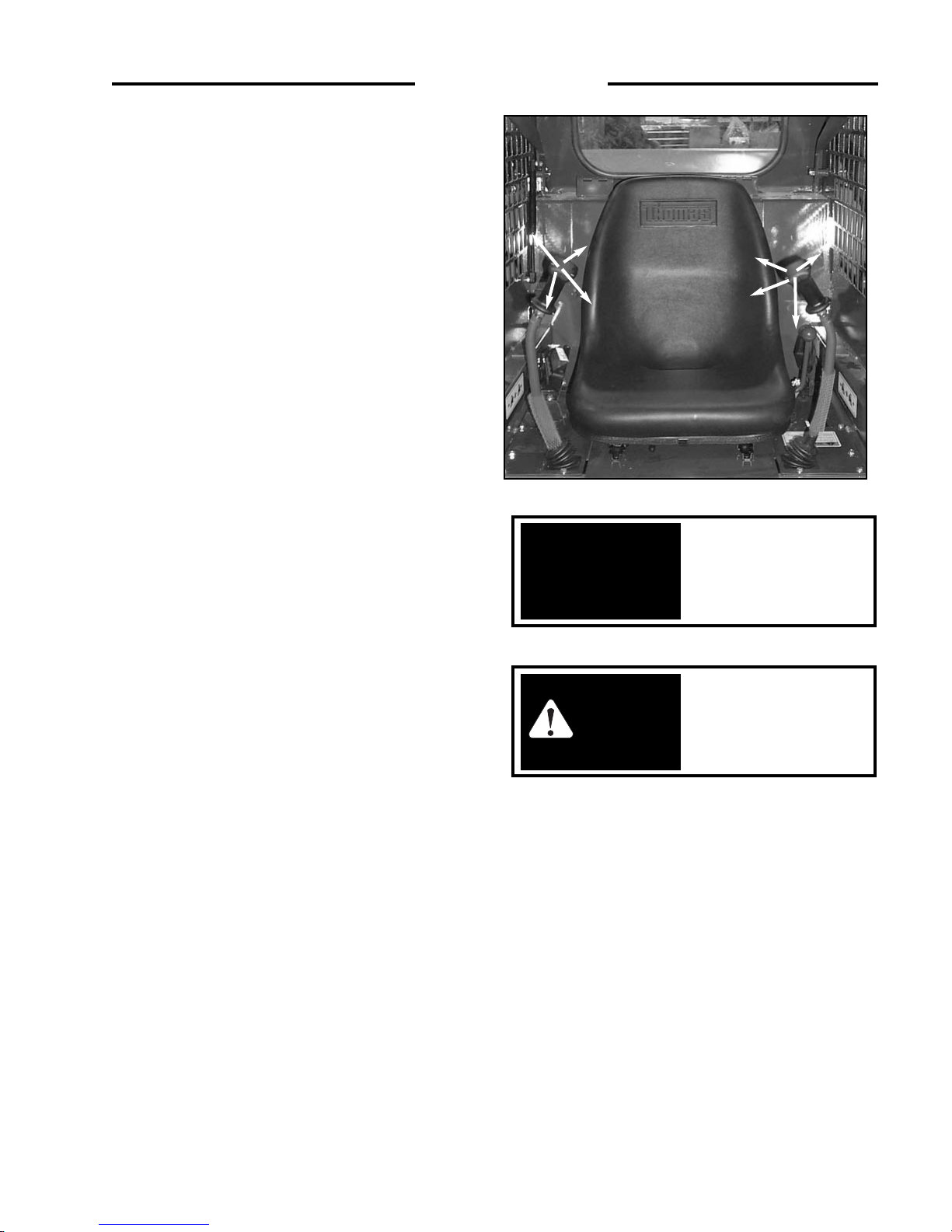
2. Seat Removal
The seat and seat plate can be removed to provide access
to the controls, hydraulic and hydrostatic components. To
remove the seat assembly, remove the fasteners located at
the front of the seat. Disconnect the electrical plug!! Lift
the seat assembly out of the machine. When installing the
seat, be sure the seat plate locks are in place at the rear
(Fig. 4. 4B).
Fully retract pins before
raising or lowering lift
arms.
IMPORTANT
To avoid personal injury:
Do not leave lift arms up
unless the lift arm locks
are engaged.
WARNING
C-729 Fig. 4. 4A1
C-730
Fig. 4. 4A2
4...MAINTENANCE
C-796
fig. 4.4B
Seat Switch
Electrical Plug
Page 36

36
4. 5 FINAL DRIVE MAINTENANCE
1. Oil Level Check
The loader has two independent final drive housings. Check
the lubricating oil level with the loader on a level surface.
Remove the check plug (Fig. 4. 5A) located on the front of
the frame to determine the oil level. The oil level should be
checked after 50 operating hours and every 150 hours
thereafter. It is recommended the oil be changed after 1000
operating hours of if it shows signs of contamination.
4...MAINTENANCE
Keep the rear door
closed except for
servicing. Make sure the
door is closed and
latched before operating
the loader.
IMPORTANT
Oil Drain
Plug
Oil Level
Check Plug
C-893 FIG 4.5A
C3072 4.4C2
3. Engine Compartment
The engine compartment is completely enclosed for
component protection and lockable to discourage
vandalism. For servicing, the rear door swings open and
the engine cover hinges up. To open; pull door latch
upward, releasing the door catch, grasp the door handle
and swing the door open. (See Fig. 4. 4C1). Lower the
engine cover before closing the rear door. (See Fig. 4. 4C2)
C3071
4.4C1
Door Handle
Door Latch
Engine
Cover
Page 37

37
4...MAINTENANCE
2. Adding Oil
Add oil with the loader on level ground. Remove the oil
level check plug (Fig. 4. 5A) on the final drive housing.
remove the filler cap (Fig. 4. 5B). Fill with appropriate oil
(See Section 5 for specifications) engine oil check plug
level, total capacity is 3.5 gal. (13 l).
3. Drive Chain, Axle and Sprocket Inspection
The condition of the drive chains should be checked after the
first 50 hours of operation and every 150 hours thereafter.
To inspect, block the loader securely with all four wheels
clear off the ground. Remove both the front and rear
wheels. On reassembly torque the wheel nuts to 100-110 ft.
lbs. (136-149 N m). Remove the inspection cover on the
side of the chain drive housing.
Inspect the chain for any sign of wear, damage or excessive
looseness. Inspect the sprockets for any sign of damage or
excessive wear. Inspect the lubricating oil for signs of
contamination. Check the axle bearings for loss of bearing
preload. If necessary adjust the bearings for zero end play.
4.6 HYDRAULIC/ HYDROSTATIC
SYSTEM MAINTENANCE
1. Oil Level Check
Check the oil level of the hydraulic reservoir with the
machine on a level surface with the lift arms down and the
bucket flat on the ground. Open the rear door and check
the oil level sight glass (Fig. 4.6A). If oil is apparent the
level is satisfactory.
2. Adding Oil
To add oil, remove the oil filler cap located at the top of the
oil reservoir (Fig. 4. 6B). Check the filter screen in the filler
neck for signs of damage. Add 10W30 or 20W50API
Classification SE/ CD engine oil until oil is visible in the
oil level sight glass (Fig. 4.6A).
To avoid personal injury,
lower the lift arms, shut off
the engine, raise the seat bar
and cycle the hydraulics to
ensure they are locked. Then,
unlatch the seat belt and exit
the loader. Do not enter or
exit with the engine running
unless as specified in this
manual or under specific
service and backhoe
operating procedures.
WARNING
WARNING
WARNING: Escaping
hydraulic fluid under
pressure can penetrate the
skin causing serious injury.
• DO NOT use your hand to
check for leaks. Use a piece of
cardboard or paper to search
for leaks.
• Stop engine and relieve
pressure before connecting or
disconnecting lines.
• Tighten all connections before
starting engine or pressurizing
lines.
If any fluid is injected into the
skin obtain medical attention
immediately.
C3073
FIG 4.6B
C-892
FIG 4.6A
C-896
FIG 4.5B
Filler Holes
Page 38

38
4...MAINTENANCE
3. Main Hydraulic Filter Replacement
The hydraulic oil filter must be changed after the first 50
hours operation. This filter has an indicator which
indicates a blocked filter. Change the filter when it
indicates a blocked condition or every 150 hours
whichever is first. To change the filter; shut off the engine,
lower the lift arms, ground any attachment and set the
parking brake. Open the rear door and using an oil filter
wrench remove the filter element (Fig. 4.6C). Lubricate
the new filter element with system fluid and reinstall.
4. Draining System Fluid:
Change the hydraulic oil:
1. after 1000 operating hours,
2. if the oil has become contaminated
3. after any major hydrostatic repair.
To drain the oil: remove the drain plug located at the
bottom of the reservoir (Fig. 4.6D).
Refill the hydraulic oil
reservoir with engine oil See Section 5 for appropriate
specifications).
5. Brake Service Override
A Service Override has been incorporated for use by
Thomas Dealers. The normal position of the plunger is
down and turned into the locked position.
4.7 ENGINE MAINTENANCE
1. Engine Specifications
Make . . . . . . . . . . . . . . . . . . . . . . . . . . . . . . . . Kubota
Model . . . . . . . . . . . . . . . . . . . . . . . . . . . V1505-E3B
No. of Cyls. . . . . . . . . . . . . . . . . . . . . . . . . . . . . . . . 4
H.P (kW)Gross . . . . . . . . . 35.5 (26.5) @ 3000 RPM
Max. Torque . . . . . . . . . . . . . . . . . . . . . . . 69.3 ft lbs.
. . . . . . . . . . . . . . . . . . . . . . . . (94 nm.) @ 3000 RPM
Displacement . . . . . . . . . . . . 91.41 cu. in.(1498 c.c.)
Max. High Idle . . . . . . . . . . . . . . . . . . . . . . . . . . 3000
Engine Oil Capacity . . . . . . . . . . . . 1.6 Gallons. (6 L)
Oil Pressure . . . . . . . . . . . . . . . . 28 - 64 PSI @ 3000
. . . . . . . . . . . . . . . . . . . . . . . . . . . . . . (193 - 441 kPa)
Injector Working Pressure . . . . . . . . 1991 - 2133 PSI
. . . . . . . . . . . . . . . . . . . . . . . . . . . (13. 7 - 14. 7 MPa)
Cooling System Capacity . . . . . . . . . . 3. 2 gal. (12 l)
Radiator Pressure Cap Setting . . . . . . 7 PSI (48 kPa)
Thermostat Rating . . . . . . . . . . . . . . . . 180oF (82oC)
. . . . . . . . . . . . . . . . . . . . . . . . . . . . . . . . . . . Full open
Alternator . . . . . . . . . . . . . . . . . . . . . . . . . . . . . . 60 A
OIL RESERVOIR DRAIN
C3177 FIG 4.6C
Main Hydraulic
Filter
C-734
FIG 4.6D
Service Override Plunger
C5531
WARNING
To avoid personal injury:
Stop, Cool and Clean the
engine of flammable
materials before
servicing. Never service
or adjust machine with
engine running.
Page 39

39
2. Oil Level Check
To check the oil level, stop the engine with the loader on
level ground, open the rear door and remove the dipstick
(Fig. 4. 7B1).
Keep the oil level between the full and low mark on the
dipstick (Fig. 4. 7B2). Do not fill above the full mark and
use only appropriat oil (See Section 5 for specifications).
3. Engine Oil and Filter Replacement
Operate the engine until warm, approximately 5 minutes.
Stop the engine.
Remove the cap on the oil drain hose located at the bottom
of the oil pan. (Fig 4. 7C1).
Remove the oil filter (Fig. 4. 7C2). Clean the filter housing
surface. Put clean oil on the seal of the new filter and
install the filter hand tight. Replace the oil drain plug.
Remove the filler cap and add appropriate engine oil (See
Section 5 for specifications). Start the engine and run for 5
minutes. Stop the engine and check for leaks at the filter.
Recheck the oil level and add oil until the level is at the top
mark on the dipstick.
Oil Check Daily
Oil Change 150 hrs.
Filter Change 150 hrs.
Engine Oil Drain
C-842
Fig. 4.7C1
4...MAINTENANCE
C-642
fig. 47B2
C-894
FIG 4.7C2
FIG 4.7.B1
C-880
Engine Oil Filter
Engine Fuel Filter
Page 40

4. Cooling System Fluid
The engine cooling system fluid is a 50 - 50 mixture of
ethylene glycol and water for cold - weather protection.
To drain the cooling system; attach a hose to the drain
valve located at the engine block (Fig. 4. 7D1). Remove
the radiator cap. Turn the drain valve handle so that it’s
toward the valve outlet. To completely drain the radiator
open the drain valve located at the bottom of the radiator
(Fig. 4. 7D1).
To fill the cooling system; close the drain valve on the
engine block (Fig. 4. 7D1) and refit the radiator drain plug.
Fill the radiator with a 50 - 50 mixture of ethylene glycol
and water. Refit the radiator cap.
5. Fan Belt Tension
Check the fan belt tension midway between the fan pulley
and alternator pulley (Fig. 4. 7E1). Deflection should be
between 1/4 to 3/8 in. (7 - 9 mm). Ensure the Fan Belt
Guard is replaced after the tension check.(Fig 4. 7E2).
6. Fuel Filter Replacement
The fuel filter is located in the engine compartment on the
left hand side (Fig. 4. 7F). The fuel filter should be
removed every 100 hours and any water or dirt found in
the element drained off. Change the filter every 400 hours.
To replace the filter; close the fuel inlet line shut - off
located on the side of the fuel tank (Fig. 4. 7F). Remove
the filter element (Fig. 4. 7F). Lubricate the seal on the
new filter and install the filter hand tight. Open the fuel
inlet shut-off. It is not a requirement to bleed air from the
fuel system. Follow Section 3. 1 for starting procedures.
40
4...MAINTENANCE
Alternator
Pulley
Crankshaft Pulley
Fuel Filter
fig 4.7E1
C2932
Fig 4. 7F
C - 879
C - 838
Fuel Inlet Shut-off
WARNING
To avoid personal injury:
DO NOT remove the
radiator cap when the
engine is hot.
Water Pump Pulley
Fig. 4.7D1
Radiator Drain
C-1006
fig 4. 7E2
Fan Belt Guard
Page 41

41
7. Adding Fuel
Use appropriate fuel only (See Section 5 for specification).
Total tank capacity 14.6 gal. (55 L).
Before adding fuel to the loader the key switch must be off
and the engine must be cool. Remove the fuel cap (Fig. 4.
7G). Use a clean approved safety container to add fuel.
Add fuel only in an area that is well ventilated and away
from open flames or sparks – NO SMOKING.
4. 8 AIR CLEANER MAINTENANCE
1. Daily Maintenance
Inspect the air precleaner canister for holes or dents, or
missing or mis-aligned gaskets. Check all hose clamps for
tightness and inspect the hoses for damage. Check the
vacuator for damage.
2. Servicing Cleaner Element
To replace the air filter element carry out the following:
1. Empty the dust cap as required.Dust should not
be allowed to build up closer than 1 in.
from the baffle.
2. Remove the primary element as gently as
possible. Before installing the new element
inspect the element and gasket for shipping or
storage damage.
3. Always clean the inside of the housing and
gasket seating surface making sure no
dust is allowed into the intake duct.
4. Check for uneven dirt patterns on the old
filter. Make sure the new gasket is seating
evenly. Reinstall dust cap, making sure it
seals 360 degrees around the cleaner body.
Reset the restriction indicator.
5. Check all connections between the air
cleaner and the engine to be certain they
are tight and leak - free.
4...MAINTENANCE
Fig. 4.7GC3074
VACUATOR
COVER
ASSEMBLY
INLET
PRIMARY FILTER
MAIN BODY
C - 891
OUTLET
To avoid personal injury
never add fuel to the loader
when the engine is running
or is hot. NO SMOKING.
WARNING
Page 42

4...MAINTENANCE
4.9 ELECTRICAL SYSTEM
Electrical Schematic 105
To Fuse Box
Light Kit Wire Harness
Light Kit Wire Harness
42
C3159
Page 43

43
4...MAINTENANCE
4.9 ELECTRICAL SYSTEM
Electrical Schematic 105
Light Kit Wire Harness
Light Kit
Wire Harness
Engine Wire Harness
To Switch at
Left Hand
Control Lever
C3160
Page 44

44
4...MAINTENANCE
4.9 ELECTRICAL SYSTEM
Electrical Schematic 105
Light Kit Wire Harness
ROPS
Wire Harness
C3161
Page 45

45
2. Battery Access
The battery is located behind the LH transmission, in the
engine compartment ( See Fig. 4. 9B1 & B2)).
4...MAINTENANCE
WARNING
To avoid personal injury,
lower the lift arms, shut off
the engine, raise the seat bar
and cycle the hydraulics to
ensure they are locked. Then,
unlatch the seat belt and exit
the loader. Do not enter or
exit with the engine running
unless as specified in this
manual or under specific
service and backhoe
operating procedures.
Fig 4.9B1
C-895
Fig 4.9B2
C-1004
Battery
Page 46

46
4.10 TIRE MAINTENANCE
1. Tire Inflation and Service
1. 1 Upon receiving your loader, check the air
pressure in the tires as indicated in the
table.
1. 2 Check tire pressure every 50 hours or
weekly.
1. 3 Tire inflation pressure affects the amount
of weight which a tire may carry. Do not
over or under inflate the tires.
1. 4 Do not inflate a tire above the
manufacturer’s maximum pressure shown
on the tire or the maximum pressure
shown in the table.
1. 5 Do not re - inflate a tire that has been run
flat or seriously under - inflated until the
tire has been inspected for damage by a
qualified person.
1. 6 When checking tire pressure, inspect the
tire for damaged side walls and tread cuts.
Neglected damage will lead to early tire
failure.
1. 7 Be sure the rim is clean and free of rust.
1. 8 Lubricate both tire beads and rim flanges
with soap solution. Do not use oil or
grease.
1. 9 Use a clip - on tire chuck with a remote
hose and gauge which allows the operator
to stand clear of the tire while inflating it.
1. 10 After seating the beads, adjust inflation
pressure to recommended operating
pressure.
1. 11 Do not inflate a tire unless the rim is
mounted on the loader or is secured so that
it will not move if the tire or rim should
suddenly fail.
1. 12 Do not weld, braze or otherwise repair a
rim. Do not use a damaged rim.
1. 13 Never attempt tire repairs on a public road or
highway.
1. 14 Use jack stands or other suitable blocking
to support the loader while repairing tires.
1. 15 Insure jack has adequate capacity to lift
your loader.
1. 16 Insure jack is placed on a firm level surface.
1. 17 Do not put any part of your body under the
loader or start the engine while the loader
is on the jack.
1. 18 Torque lug nuts to specification after
reinstalling wheel. Check lug not torque
hourly until torque stabilizes.
Tire Inflation Table
Tire Inflation Pressure
8.50 x 15.0 30 - 35 PSI (207 - 241 kPa)
10.50 x 15.0 30 - 35 PSI (207 - 241 kPa)
2. Tire Rotation
The front and rear tires will wear at different rates. For
even wear move the front tires to the rear and the rear tires
to the front when wear is first noticed.
If two tires become worn more than the other two put the
two worn tires on the same side.
When new tires are installed, always keep tires the same
size on the same side of the loader. Two different size tires
on the same side of the loader will cause drive chain wear,
tire wear and a loss of power.
WARNING
4...MAINTENANCE
To avoid personal injury:
Inflating or servicing
tires can be dangerous.
Trained personnel should
be called to service
and/or mount tires when
possible. In any event to
avoid possible serious or
fatal injury, follow the
safety precautions below.
WARNING
NEVER INFLATE
TIRES TO OVER 240
KPA (35 PSI) TO SEAT
BEADS. If beads have not
seated by the time
pressure reaches 240 KPa
(35 PSI), deflate the
assembly, reposition the
tire on the rim,
relubricate both tire
beads, rim flanges and re-
inflate. INFLATION
Beyond 240 KPa (35 PSI)
with unseated beads may
break the bead or rim
with EXPLOSIVE force,
sufficient to cause serious
injury.
Page 47

47
PROBLEM CAUSE REMEDY
Loss of
hydraulic
power (no
flow from
gear pump)
Loss of
hydraulic
power (flow
from gear
pump)
Hydraulic
action jerky
Reservoir low on
fluid hose or fitting
leak.
Flexible coupling
between engine and
pump failure
Spline coupling
failure between front
and rear hydrostatic
pump
Hydraulic gear pump
not functioning
Reservoir low on
fluid
Foot pedal linkage
disconnected or
binding
Auxiliary foot
pedal engaged
Relief valve failure in
control valve
Reservoir low on oil
Air in hydraulic
system
Replenish with
appropriate oil (See
Section 5 for
specifications). Check for
leaks.
Inspect and replace
damaged parts. Check for
misalignment between
engine and
pumps.
Inspect coupling for
sheared splines. Also
check pump shaft
bearings.
Inspect and repair.
Replenish with
appropriate oil (See
Section 5 for
specifications).
Inspect and adjust.
Disengage
Check pressure and
adjust.
Replenish with
appropriate oil (See
Section 5 for
specifications).
Check for leak
between reservoir
and pump. Bleed System
by extending and
retracting lift cylinders
several times.
Power Cause Remedy
4...MAINTENANCE
1. Hydrostatic Drive
4. 11 TROUBLESHOOTING
2. Hydraulic System
Power
No power on
one side (both
directions)
No power on
one side (one
direction only)
No power on
both sides, also
loss of hyd.
power
Gradule loss of
power as
machine warms
up
Cause
Reservoir low on
oil
Disconnected
control linkage
Groove pin
sheared on pump
pintle lever
High pressure line
failure
Drive chain
failure.
Adjust tightener
tension.
Motor shaft or key
failure. Check
mounting bolts.
Excessive internal
leakage in motor
and/or pump.
Defective relief
valve
Damaged ball
check
Reserve low on
oil.
Pump coupling
failure
Check system
pressure
Excessive internal
leakage in pump
and/or motor.
Remedy
Replenish with
appropriate oil (See
Section 5 for
specifications). Check
for hose or fitting leak.
Reconnect and adjust
linkage.
Replace. Check pintle
lever for loose bolt or
excessive play.
Replace line. Ensure
new line fits without
being forced. If
necessary, stress relieve.
Replace chain or
connection link.
Inspect and repair
defective parts.
Inspect and repair
defective unit. Flush all
lines and tank. Replace
filter. Check on type of
fluid used and engine
RPM.
Replace defective valve.
Disassemble and repair.
Replace with appropriate
oil (See Section 5 for oil
specifications).
If damaged, consult
dealer or Thomas
Service Dept.
If low, consult dealer or
Thomas Service Dept.
Consult dealer or
Thomas Service Dept.
System erratic
and/or noisy
Machine will not
travel in a
straight line in
high range
Air in system due to
low oil level in
reservoir
Air in system due to
leak at suction fitting
Internal pump or
motor wear caused
by overspeeding
Excessive play in
linkage or pintle
lever
Control levers
binding
Replenish using
appropriate oil (See
Section 5 for
specifications)
Check fittings and
tighten.
Consult your dealer or
Thomas Service Dept.
Adjust linkage and
tighten or replace pintle
lever.
Check that shields are
not stopping lever from
full travel.
Check for linkage
binding at spring mount.
Adjust tracking.
Page 48

48
Control levers
will not centre
Machine operates
erratically
Machine will not
travel in straight
line
Linkage out of
adjustment
Linkage
disconnected
Centering spring
broken
Linkage binding
Control lever
linkage loose
Spiral pin in pintle
lever worn or
broken
Linkage binding
Control lever
travel out of
adjustment
Adjust, check for wear at
rod ends, loose counter
nuts
Reconnect, check for wear
at rod ends, loose counter
nuts
Replace
Binding of spring bushing
in spring box. Align spring
box with linkage.
Control levers binding
with safety shields or
sound insulation Adjust
Control lever bearings
binding in lever assy.
Inspect replace or clean as
required
Inspect linkage for wear at
rod ends, loose counter
nuts
Replace pin. Inspect pintle
lever for wear at pin hole.
Ensure bolt clamping lever
to pump shaft is tight
See hydrostatic system
Adjust
Adjust
Final drive
transmission
noisy
No lubricating oil
Axles have too
much end play
Chain loose
Check and bring oil to
the proper level. Use
appropriate engine oil
(See Section 5 for
specifications).
Pre-load axle bearings
removing all end play
Replace the chain
3. Final Drive Transmission
Foot pedals do
not operate
smoothly
Foot pedal linkage
out of adjustment
Foot pedal
linkages need
lubrication
Cable Binding
Adjust foot pedal
linkages
Lubricate with a
silicone based lubricant
Check routing for kinks
etc.
Lift arms raise
slowly at full
engine rpm
Lift or tilt
cylinders will not
support a load
Hydraulic oil
overheating
Anti-cavitation
check valve not
functioning
Reservoir low on
oil
Foot pedal linkage
binding
Auxiliary foot
pedal engaged
Engine RPM too
slow
Anti-cavitation
check valve spring
broken
Main relief valve
in control valve
faulty
Internal leakage in
pump due to wear
Oil bypassing one
or both lift
cylinder piston
seals
External leak
between or at
control valve and
cylinders
Control valve
spool not
centering
Oil leaking by one
or both cylinder
piston seals
Reservoir low on
fluid
Auxiliary foot
pedal engaged
Engine RPM too
slow
Incorrect
temperature
sensor
Inspect and repair or
replace
Replenish with appropriate
oil (See Section 5 for
specifications).
Inspect and adjust
Disengage
Check RPM and reset
Replace
Check pressure if
necessary - adjust
Check pump flow and
repair or replace as
necessary
Install new piston seal kits
Check for leaks and
correct
Check for sticking foot
pedal linkage
Check for broken or stuck
return spring on valve
spool
Install new piston seal kits
Replenish with appropriate
oil(See Section 5 for
specifications).
Disengage
Check RPM and adjust
Replace
4...MAINTENANCE
4. Control Levers
Page 49

49
4...MAINTENANCE
Engine will not
crank over
Engine cranks
over, but will not
start
Loader starts, but
foot pedals will
not release
Engine will not
stop when the
key is tuned OFF
Battery failure
Battery cable
failure
Starter failure
Fuse burnt
Defective relay
Ignition switch
failure
Auxiliary
hydraulics
engaged
Defective glow
plug relay
Defective glow
plugs
Broken connection
or defective wire
No fuel
Electro solenoids
not releasing valve
spools
Defective fuel
solenoid switch
Check battery, charge or
replace
Check for loose or
corroded connectors.
tighten and clean as
required. Use di-electric
grease to prevent
corrosion.
Check continuity of cables
and replace if defective
Repair or replace
Check and replace
Check relay continuity if
defective, replace
Check continuity and if
defective, replace
Engine will smoke but not
run unassisted by starter.
Disengage aux. hydraulics
Check continuity and if
defective, replace
Check continuity and if
defective, replace
Disconnect the ROPS
harness from the engine
harness. Open the dash
panel and check continuity
of the circuit not
functioning properly in
both engine and ROPS
harness.
Check fuel levels and
system
Defective solenoid or
solenoid lock. Loosen
screws and readjust
Check and correct
6. Electrical
Control levers do
not operate
smoothly
Internal pump
and/or motor
leakage
Control lever
linkages out of
adjustment
See troubleshooting
hydrostatic system
Adjust control lever
linkages
4. Control Levers
Brake will not
hold machine
Brake will not
release machine
Brake valve will
not release
pressure
Brake parts
damaged or worn
Brakes are
disengaged
No power to brake
valve solenoid
No pressure in
supply line to
brake valve
Brakes are
engaged
Verify position of override
Sect 4.6 - 5
Consult your Dealer or
Thomas Service Dept.
Engage parking brake
Check fuse, If fine, consult
Dealer or Thomas Service
Dept.
Consult your Dealer or
Thomas service Dept.
Release brake
5. Park Brake
Page 50

50
PROBABLE CAUSE
No fuel
Air in the fuel
Water in the fuel
Fuel pipe clogged
Fuel filter clogged
Excessively high viscosity of fuel or engine oil at low
temperature
Fuel with low cetane number
Fuel leak due to loose injection pipe retaining nut
Incorrect injection timing
Fuel cam shaft worn
Injection nozzle clogged
Injection pump malfunctioning
Seizure of crankshaft, camshaft, piston, cylinder liner
or bearing
Compression leak from cylinder
Improper valve timing
Piston ring and liner worn
Excessive valve clearance
Battery discharged
Starter malfunctioning
Key switch malfunctioning
Wiring disconnected
Fuel filter clogged or dirty
Air cleaner clogged
Fuel leak due to loose injection pipe retaining nut
Injection pump malfunctioning
Incorrect nozzle opening pressure
Injection nozzle stuck or clogged
Fuel overflow pipe clogged
Governor malfunctioning
Excessive engine oil
Low grade fuel used
Fuel filter clogged
Air cleaner clogged
Overload
Low grade fuel used
fuel filter clogged
air cleaner clogged
SOLUTION
Replenish fuel
Vent air
Change fuel and repair or replace
fuel system
Clean
Clean or change
Use the specified fuel or engine oil
Use the specified fuel
Tighten nut
Adjust
Replace
Clean
Repair or replace
Repair or replace
Replace head gasket, tighten
cylinder head bolt, glow plug and
nozzle holder
Correct or replace timing gear
Replace
Adjust
Charge
Repair or replace
Repair or replace
Connect
Clean or change
Clean or change
Tighten nut
Repair or replace
Adjust
Repair or replace
Clean
Repair
Reduce to the specified level
Repair or replace
Adjust
Adjust top clearance
Lessen the load
Use the specified fuel
Clean or change
Clean or change
SYMPTOM
Engine does not start
Starter does not run
Engine revolution is not smooth
Either white or blue exhaust gas is
observed
Either black or dark gray exhaust gas is
observed
4...MAINTENANCE
7. Diesel Engine
Page 51

51
PROBABLE CAUSE
Piston rings gap facing the same direction
Oil ring worn or stuck
Piston ring groove worn
Valve stem and guide worn
Crankshaft bearing and crank pin bearing worn
Injection pump plunger worn
Injection pump broken
Head gasket defective
Cylinder block or cylinder head flawed
Engine oil insufficient
Oil strainer clogged
Relief valve stuck with dirt
Relief valve spring weakened or broken
Excessive oil clearance of crankshaft bearing
Excessive oil clearance of crank pin bearing
Excessive oil clearance of rocker arm bearing
Oil passage clogged
Oil pump defective
Different type of oil
Relief valve defective
Engine oil insufficient
Fan belt broken or elongated
Cooling water insufficient
Radiator net and radiator fin clogged with dust
Inside of radiator corroded
Cooling water flow route corroded
Radiator cap defective
Overload running
Head gasket defective
Incorrect injection timing
Unsuitable fuel used
Incorrect injection timing
Engine’s moving parts seem to be seizing
Uneven fuel injection
Deficient nozzle injection
Compression leak
Battery electrolyte insufficient
Fan belt slips
Wiring disconnected
Rectifier defective
Alternator defective
Battery defective
4...MAINTENANCE
7. Diesel Engine
SYMPTOM
Excessive lubricant oil consumption
Fuel mixed into lubricant oil
Water mixed into lubricant oil
Low oil pressure
High oil pressure
Engine overheated
Deficient output
Battery quickly discharges
SOLUTION
Shift gap direction
Replace
Replace
Replace
Replace
Replace pump element or pump
Replace
Replace
Replace
Replenish
Clean
Clean
Replace
Replace
Replace
Replace
Clean
Use the specified oil type
Use the specified oil type
Replace
Replenish
Change or adjust
Replenish
Clean
Clean or replace
Clean or replace
Replace
Loosen the load
Replace
Adjust
Use the specified fuel
Adjust
Repair or replace
Repair or replace injection pump
Repair or replace nozzle
Replace head gasket, tighten
cylinder head bolt, glow plug and
nozzle holder
Replenish distilled water recharge
Adjust belt tension or change
Connect
Replace
Replace
Change
Page 52

52
4...MAINTENANCE
4.12 HYDRAULIC/HYDROSTATIC CIRCUIT
Oil Filter
10 Micron
Brake Coupler
Control
Valve
Hydraulic Gear
Pump
Oil Filter 100 Micron
Hydrostatic
Pump
Torque
Motor
Brake Valve
Oil Reservoir
Torque
Motor
C3162
Oil Cooler
Page 53

53
Lift Cylinders
Auxiliary Hydraulics
Tilt Cylinders
Control
Valve
4...MAINTENANCE
4.12 HYDRAULIC/HYDROSTATIC CIRCUIT
C-1008
Page 54

54
4...MAINTENANCE
4.13 SPECIAL TOOLS
T133
T133’S’
T103
T103S
T133
T133’S’
ALL
LOADERS
T173
T233
T173HL
T173HL’S’II
T203HD
T233HD
T243HD’S
T103
T133
T133’S’
ALL
MODELS
P/N
ILLUSTRATION DESCRIPTION MODEL
955280
AXLE INSTALLATION TOOL - To install
axle in final drive housing.
Quantity - 1
960849
955281
SEAL INSTALLATION TOOL - To install axle
seal in final drive housing.
Quantity - 3 required
955283
AXLE EXTRACTOR TOOLS- To remove axle
from final drive housing.
Quantity - 2
955287
SEAL INSTALLATION TOOL - To install axle
seal in final drive housing.
Quantity - 1
957189
SEAL INSTALLATION TOOL - To install axle
seal in final drive housing.
Quantity - 1
959849
CHAIN TENSION TOOL - To test chain tension.
U-1288
Universal Tool Kit
1 each. Combination wrench 7/16”, 1/2”,
9/16”,11/16” 3/4”, 1 1/16”,1 1/4”. Sockets, 1”,
1/2” drive, 7/8”, 1/2” drive, tool pouch, allen
wrench 5/32” and 1/8”
Page 55

55
916 - 30042-01
25197
07909 - 30202-01
25198
07916 - 30820-01
25199
07916 - 30840-01
25200
70090 - 01125-01
25201
960456
DRY LINER PULLER - Used for removing and
installing the dry liner of the engine.
Consists of:
304742 (64mm); 304743 (68mm); 30744 (75mm)
304745 (76mm); 304746 (82mm); 304747
(105mm); Removing Plates; 304748 Installing
Plate
DIESEL ENGINE COMPRESSION TESTER Used to measure diesel engine compression and
diagnosis of need for major overhaul.
CRANKSHAFT NUT SOCKET - Used to take off
and fix the crankshaft nut. (46 mm).
NOZZLE REMOVER SOCKET - Used to
unfasten the screw type nozzle holders.
NOZZLE DISASSEMBLY SOCKET - Used in
place of a vice for disassembly and repair of
nozzles.
HYDRAULIC FLOW AND PRESSURE GAUGE
ASSEMBLY.
KUBOTA
KUBOTA
KUBOTA
KUBOTA
KUBOTA
All Models
Order # Illustration Description Models
4...MAINTENANCE
4.13 SPECIAL TOOLS
Page 56

56
TOOTHED BELT TENSION GAUGE
Quantity -1
ADJUSTING PIN FOR
CRANKSHAFT AND CAMSHAFT
T243 HDS
T243HDS
Order # Illustration Description Models
4...MAINTENANCE
42530
42531
4.13 SPECIAL TOOLS
Page 57

57
5...SPECIFICATIONS
5...SPECIFICATIONS
5. 1 Loader Specifications
5. 2 Torque Specifications
5. 3 Sound Power Level
5. 4 Decals, Warning
Page 58

58
5...SPECIFICATIONS
Dimensions – 5. 1: (With Std. Tires & Dirt Bucket)
A. Overall operating height . . . . . . . . . . . . . . . . . . . . . . . . . . . . . . . . . . . . . . . . . . . . . . . . . . . . . . . . . 134. 5” (3416 mm)
B. Height to hinge pin . . . . . . . . . . . . . . . . . . . . . . . . . . . . . . . . . . . . . . . . . . . . . . . . . . . . . . . . . . . . . . 102.5” (2604 mm)
C. Overall vehicle height with ROPS . . . . . . . . . . . . . . . . . . . . . . . . . . . . . . . . . . . . . . . . . . . . . . . . . . . . . 71” (1803 mm)
D. Overall length with bucket . . . . . . . . . . . . . . . . . . . . . . . . . . . . . . . . . . . . . . . . . . . . . . . . . . . . . . . . . 115” (2921 mm)
E. Dump angle . . . . . . . . . . . . . . . . . . . . . . . . . . . . . . . . . . . . . . . . . . . . . . . . . . . . . . . . . . . . . . . . . . . . . . . . . . . . . . . . 30°
F. Dump height . . . . . . . . . . . . . . . . . . . . . . . . . . . . . . . . . . . . . . . . . . . . . . . . . . . . . . . . . . . . . . . . . . . . 81.5” (2070 mm)
G. Reach — fully raised . . . . . . . . . . . . . . . . . . . . . . . . . . . . . . . . . . . . . . . . . . . . . . . . . . . . . . . . . . . . . 22.75” (578 mm)
H. Height at 45° dump angle . . . . . . . . . . . . . . . . . . . . . . . . . . . . . . . . . . . . . . . . . . . . . . . . . . . . . . . . . 54.75” (1391 mm)
I. Reach at 45° dump angle . . . . . . . . . . . . . . . . . . . . . . . . . . . . . . . . . . . . . . . . . . . . . . . . . . . . . . . . . . . . 27” (686 mm)
J. Maximum roll back at ground . . . . . . . . . . . . . . . . . . . . . . . . . . . . . . . . . . . . . . . . . . . . . . . . . . . . . . . . . . . . . . . . . 32°
K. Maximum roll back fully raised . . . . . . . . . . . . . . . . . . . . . . . . . . . . . . . . . . . . . . . . . . . . . . . . . . . . . . . . . . . . . . . . 97°
M. Wheel base . . . . . . . . . . . . . . . . . . . . . . . . . . . . . . . . . . . . . . . . . . . . . . . . . . . . . . . . . . . . . . . . . . . . . 33.18” (843 mm)
N. Overall length less bucket . . . . . . . . . . . . . . . . . . . . . . . . . . . . . . . . . . . . . . . . . . . . . . . . . . . . . . . . . . . 91” (2311 mm)
O. Ground clearance . . . . . . . . . . . . . . . . . . . . . . . . . . . . . . . . . . . . . . . . . . . . . . . . . . . . . . . . . . . . . . . . . 6.75” (171 mm)
P. Maximum grading angle – bucket . . . . . . . . . . . . . . . . . . . . . . . . . . . . . . . . . . . . . . . . . . . . . . . . . . . . . . . . . . . . . . 80°
Q. Angle of departure . . . . . . . . . . . . . . . . . . . . . . . . . . . . . . . . . . . . . . . . . . . . . . . . . . . . . . . . . . . . . . . . . . . . . . . . . . 23°
R. Bucket width . . . . . . . . . . . . . . . . . . . . . . . . . . . . . . . . . . . . . . . . . . . . . . . . . . . . . . . . . . . . . . . . . . . . . . 48” (1219mm)
S. Clearance circle – front – less bucket . . . . . . . . . . . . . . . . . . . . . . . . . . . . . . . . . . . . . . . . . . . . . . . . . . 41” (1041 mm)
T. Clearance circle – front – with bucket . . . . . . . . . . . . . . . . . . . . . . . . . . . . . . . . . . . . . . . . . . . . . . . 66.25” (1683 mm)
U. Clearance circle – rear . . . . . . . . . . . . . . . . . . . . . . . . . . . . . . . . . . . . . . . . . . . . . . . . . . . . . . . . . . . . . . 54” (1372 mm)
V. Overall width – less bucket . . . . . . . . . . . . . . . . . . . . . . . . . . . . . . . . . . . . . . . . . . . . . . . . . . . . . . . 47.75” (1213 mm)
W. Tread . . . . . . . . . . . . . . . . . . . . . . . . . . . . . . . . . . . . . . . . . . . . . . . . . . . . . . . . . . . . . . . . . . . . . . . . . . . . . . . 38.5” (978)
Performance
Rated operating capacity . . . . . . . . . . . . . . . . . . . . . . . . . . . . . . . . . . . . . . . . . . . . . . . . . . . . . . . . . . . . 1000 lbs. (454 kg)
Operating weight . . . . . . . . . . . . . . . . . . . . . . . . . . . . . . . . . . . . . . . . . . . . . . . . . . . . . . . . . . . . . . . . . 3650 lbs. (1656 kg)
Shipping weight . . . . . . . . . . . . . . . . . . . . . . . . . . . . . . . . . . . . . . . . . . . . . . . . . . . . . . . . . . . . . . . . . . 3150 lbs. (1429 kg)
Speed . . . . . . . . . . . . . . . . . . . . . . . . . . . . . . . . . . . . . . . . . . . . . . . . . . . . . . . . . . . . . . . . . 3000 RPM 5.8 mph (9.3 km/hr)
Tipping Load . . . . . . . . . . . . . . . . . . . . . . . . . . . . . . . . . . . . . . . . . . . . . . . . . . . . . . . . . . . . . . . . . . . . . . 2100 lbs. (953 kg)
5. 1 LOADER SPECIFICATIONS
Page 59

59
5...SPECIFICATIONS
Controls
VEHICLE: Steering direction and speed controlled
by two hand operated control levers.
HYDRAULICS: Lift, bucket tilt and auxiliary hydraulic
functions controlled by separate foot
pedals.
ENGINE: Hand lever throttle, engine stop and key
type ignition switch.
Engine
Make and model ................................Kubota V1505-E3B
Cylinders...........................................................................4
Cooling system ........................................................Liquid
Displacement ................................91.41 cu. in. (1498 cc)
Horsepower (kW) Gross ..........35.5 (26.5) @ 3000 RPM
Torque ..............................................69.3 ft. lbs (94 N.m.)
Fuel type .........................Low or Ultra Low Sulfer Diesel
Air cleaner ...............................Replaceable Dry Cartridge
....................................................................w/ indicator
Maximum governed RPM (no load).................3000 RPM
Hydraulic System
Pump type ...................................................................Gear
Pump capacity.................................8.7 GPM / 3000 RPM
......................................................33 L/M / 3000 RPM
Control valve ............. Parallel type with float on lift and
.........................................................detent on auxiliary
System relief pressure (Zero Flow) ................... 2200 PSI
.................................................................... (151.5 Bar)
Filtration ............................................................. 5 micron
Hydraulic fluid .............................. 10W30 API Class, SJ
.....................................................20W50 API Class, SJ
Oil Cooler...............................250 BTU/min (264 kJ/min)
Engine Oil ...................................................5W40 API CF
Cylinders (double acting) Lift Tilt
Bore dia. 2 in. 2 in.
Rod dia. 1.125 in. 1.125 in.
Hydrostatic Transmission & Final Drive
Pump type .................................. Two in line, axial piston
Pump displacement ............................ 1.5 cu. in. (25 cm
3
)
Motor type ..................................... Geroler, torque motor
System relief setting ..........................3625 PSI (250 Bar)
Final drive ................................... No. 60 HT roller chain
....................................................running in an oil bath
Electrical
Alternator.....................................................................60A
Battery ........................................................................12 V
Type ...........................................................................34/78
Cranking amps..............................................................730
Reserve capacity...........................................................125
Starter..........................................................................12 V
Tires
Standard ....................................................8.50 x 15, 4 ply
Flotation ..................................................10.50 x 15, 4 ply
...............................................30 - 35 PSI (207 - 241 kPa)
Fluid Capacities
Fuel tank ..................................................11.3 gal. (43 L)
Final drive transmission ..........................5.9 gal. (22.3 L)
Hyd. Reservoir ................................................9 gal (34 L)
Engine cooling system ............................3.2 gal. (12.1 L)
Engine oil................................................1.6 Gallons (6 L)
Page 60

60
5. 2 TORQUE SPECIFICATIONS
Loader
Wheel nuts (32) . . . . . . . . . . . . . . . . . . . 100 - 110 lbs. ft.
. . . . . . . . . . . . . . . . . . . . . . . . . . . . . . .(136 - 149 N m)
Hydrostatic pump mtg. bolts (4) . . . . . . . . 80 - 85 lbs. ft.
(109 - 115 N m)
Hydraulic / Hydrostatic
Gear pump section bolts . . . 25 - 28 lbs. ft. (34 - 38 N m)
Piston pump section bolts . . . . . . . . . . . . . 27 - 31 lbs. ft.
. . . . . . . . . . . . . . . . . . . . . . . . . . . . . . . . .(37 - 42 N m)
Torque motor section bolts . . . . . . . 70 lbs. ft.. (9.4 N m)
Hydraulic filter, case . . . . . . . . . . . . . 30 lbs. ft. (41 N m)
Bolts & Nuts Torque lbs. ft. (N m)
1/4-20 . . . . . . . . . . . . . . . 5 - 7 (6. 7 - 9. 5)
5/16-18 . . . . . . . . . . . . . . 12 - 15 (16 - 20)
5/16-24 . . . . . . . . . . . . . . 12 - 15 (16 - 20)
3/8-16 . . . . . . . . . . . . . . . 17 - 22 (23 - 30)
3/8-24 . . . . . . . . . . . . . . . 22 - 27 (30 - 37)
7/16-14 . . . . . . . . . . . . . . 30 - 35 (41 - 47)
7/16-20 . . . . . . . . . . . . . . 40 - 45 (54 - 61)
1/2-13 . . . . . . . . . . . . . . . 45 - 50 (61 - 68)
1/2-20 . . . . . . . . . . . . . . . 50 - 60 (68 - 81)
9/16-12 . . . . . . . . . . . . . . 60 - 70 (81 - 95)
9/16-18 . . . . . . . . . . . . . 65 - 75 (88 - 102)
5/8-18 . . . . . . . . . . . 100 - 110 (136 - 139)
5.3 Sound Power Level Specification
LPA Sound level at operators ear. . . . . . . . . . .83 dB(A)
LWA Adjusted sound level . . . . . . . . . . . . . . .96 dB(A)
5...SPECIFICATIONS
Page 61

61
1
2
3
4
5
6
7
8
9
10
11
12
13
14
15
16
17
24
34
32
5. 4 DECAL CHART
30
TH31291
LENT
LENTO
LANGSAM
SLOW
RAPIDE
RAPIDO
SCHNELL
FAST
Page 62

62
CAUTION
TH23312
TH41064
19
20
21
22
23
25
26
27
28
28
29
36
37
On top of Radiator
5. 4 DECAL CHART
34
40A
TH43144
AUX
10A
10A
10A
OPTIONS
P
10A
10A
STOP
OPTIONS
10A
40A
SM
40A
Page 63

63
5. 4 DECAL CHART
1. 39196
2. 42107
3. 23324
4. 35886
5. 37060
6. 23301
7. 35935
8. 25460
9. 36598
10. 35885
11. 37059
12. 41045
13. 31291
14. 23326
15. 41066
16. 23309
17. 32275
18. 44615
19. 23308
20. 23307
21. 38043
22. 38044
23. 23312
24. 36841
25. 23321
26. 41064
27. 23310
28. 23325
29. 43144
30. 39191
31. 41065
32. 43145
33. 47265 (Kit)
(Up to S/N
LC001999)
T105 DECAL PARTS LIST
18
33
34
33
35
30
33. 52768 (Kit)
(S/N LC002000
Onward)
34. 39192
35. 44616
36. 37010
37. 42108
31
A806 / ECP
TH44615
A806 / ECP
TH44615
Page 64

64
6...ATTACHMENTS AND BUCKETS
6. 1 Thomas Approved Buckets and Attachments
6...ATTACHMENTS AND BUCKETS
Page 65

6...ATTACHMENTS AND BUCKETS
Cat. # Description SAE Heaped Capacity (ft3) Approx. Weight
2093 48 inch Dirt Bucket 8. 8 274 lb.
2059 54 inch Bucket 9. 9 301 lb.
BUCKETS - DIRT/CONSTRUCTION
65
6.1 THOMAS APPROVED BUCKETS AND ATTACHMENTS
Cat. # Description Approx. Weight
2096 Pallet Fork Frame (Requires Tines) 120 lb.
99 30” Tines (Set of Two) 110 lb.
98 36” Tines (Set of Two) 138 lb.
437 42” Tines (Set of Two) 149 lb.
2564 48” Tines (Set of Two) 160 lb.
PALLET FORK
Cat. # Description Approx. Weight
1536 HH 150-150 ft. lb. Class Hydraulic Breaker 250 lb.
1693 Side Plates 120 lb.
2144 Breaker Mount 190 lb.
1530 Moil Point - HH150 25 lb.
1531 Chisel Point - HH150 25 lb.
1532 Blunt Point - HH150 25 lb.
1567 Asphalt Point - HH150 25 lb.
1568 Tamping Pad 8x8 - HH150 70 lb.
1548 Gas Charger 2 lb.
HYDRAULIC BREAKER
 Loading...