

Page 1
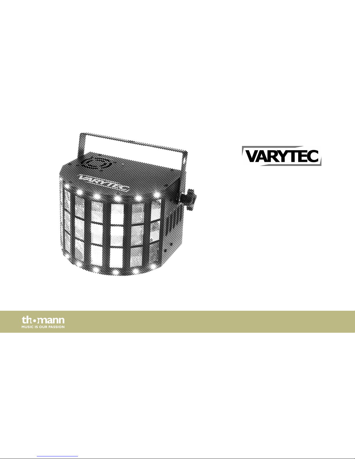
LED Derby ST
LED effect
user manual
Page 2

Musikhaus Thomann
Thomann GmbH
Hans-Thomann-Straße 1
96138 Burgebrach
Germany
Telephone: +49 (0) 9546 9223-0
E-mail: [email protected]
Internet: www.thomann.de
02.06.2017, ID: 390843
Page 3
Table of contents
1 General notes............................................................................................................................................... 5
1.1 Further information........................................................................................................................... 6
1.2 Notational conventions.................................................................................................................... 7
1.3 Symbols and signal words............................................................................................................... 7
2 Safety instructions.................................................................................................................................. 10
3 Features....................................................................................................................................................... 15
4 Installation.................................................................................................................................................. 16
5 Starting up.................................................................................................................................................. 21
6 Connections and controls................................................................................................................... 24
7 Operating.................................................................................................................................................... 29
7.1 Starting the device........................................................................................................................... 29
7.2 Main menu.......................................................................................................................................... 29
7.3 Menu overview................................................................................................................................. 33
7.4 Functions in 1-channel DMX mode........................................................................................... 34
7.5 Functions in 4-channel DMX mode........................................................................................... 35
Table of contents
LED Derby ST
3
Page 4
8 Technical specifications....................................................................................................................... 39
9 Plug and connection assignments.................................................................................................. 40
10 Troubleshooting...................................................................................................................................... 41
11 Cleaning....................................................................................................................................................... 43
12 Protecting the environment.............................................................................................................. 44
Table of contents
LED effect
4
Page 5
1 General notes
This manual contains important instructions for the safe operation of the unit. Read and follow
the safety instructions and all other instructions. Keep the manual for future reference. Make
sure that it is available to all those using the device. If you sell the unit please make sure that
the buyer also receives this manual.
Our products are subject to a process of continuous development. Thus, they are subject to
change.
General notes
LED Derby ST
5
Page 6
1.1 Further information
On our website (www.thomann.de) you will find lots of further information and details on the
following points:
Download This manual is also available as PDF file for you to download.
Keyword search
Use the search function in the electronic version to find the topics of
interest for you quickly.
Online guides
Our online guides provide detailed information on technical basics
and terms.
Personal consultation For personal consultation please contact our technical hotline.
Service
If you have any problems with the device the customer service will
gladly assist you.
General notes
LED effect
6
Page 7
1.2 Notational conventions
This manual uses the following notational conventions:
The letterings for connectors and controls are marked by square brackets and italics.
Examples: [VOLUME] control, [Mono] button.
Texts and values displayed on the device are marked by quotation marks and italics.
Examples: ‘24ch’ , ‘OFF’.
1.3 Symbols and signal words
In this section you will find an overview of the meaning of symbols and signal words that are
used in this manual.
Letterings
Displays
General notes
LED Derby ST
7
Page 8
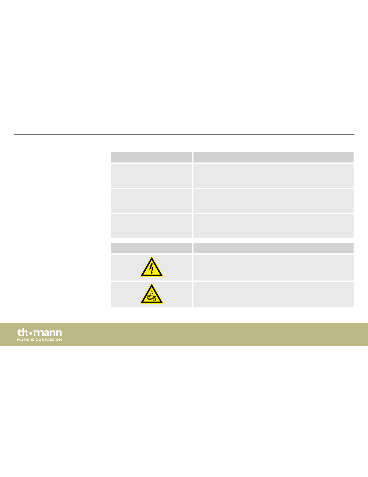
Signal word Meaning
DANGER! This combination of symbol and signal word indicates an
immediate dangerous situation that will result in death or
serious injury if it is not avoided.
WARNING! This combination of symbol and signal word indicates a pos‐
sible dangerous situation that can result in death or serious
injury if it is not avoided.
NOTICE! This combination of symbol and signal word indicates a pos‐
sible dangerous situation that can result in material and
environmental damage if it is not avoided.
Warning signs Type of danger
Warning – high-voltage.
Warning – suspended load.
General notes
LED effect
8
Page 9
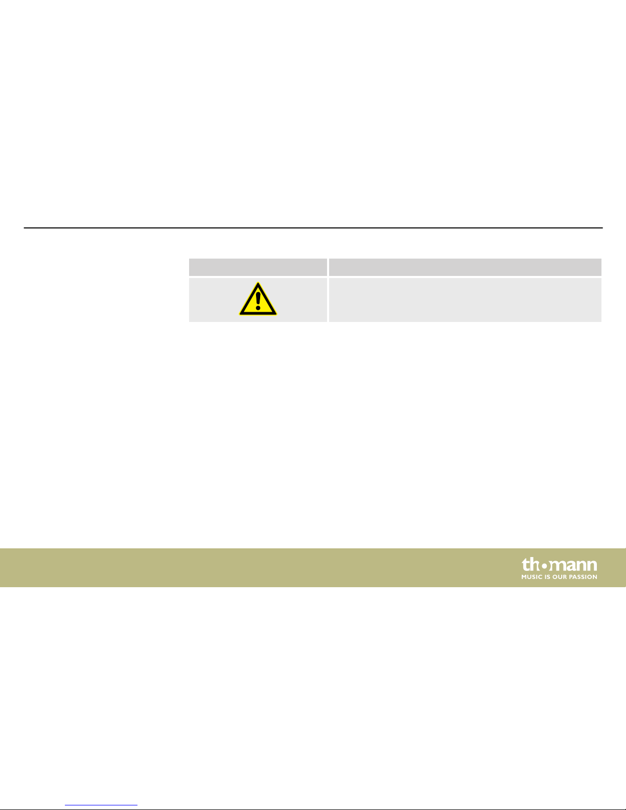
Warning signs Type of danger
Warning – danger zone.
General notes
LED Derby ST
9
Page 10
2 Safety instructions
This device is intended to be used as an electronic illumination effect using LED technics. The
device is designed for professional use and is not suitable for use in households. Use the
device only as described in this user manual. Any other use or use under other operating con‐
ditions is considered to be improper and may result in personal injury or property damage. No
liability will be assumed for damages resulting from improper use.
This device may be used only by persons with sufficient physical, sensorial, and intellectual
abilities and having corresponding knowledge and experience. Other persons may use this
device only if they are supervised or instructed by a person who is responsible for their safety.
Intended use
Safety instructions
LED effect
10
Page 11
DANGER!
Danger for children
Ensure that plastic bags, packaging, etc. are disposed of properly and are not
within reach of babies and young children. Choking hazard!
Ensure that children do not detach any small parts (e.g. knobs or the like) from
the unit. They could swallow the pieces and choke!
Never let children unattended use electrical devices.
DANGER!
Electric shock caused by high voltages inside
Within the device there are areas where high voltages may be present. Never
remove any covers.
There are no user-serviceable parts inside.
Do not use the device if covers, protectors or optical components are missing or
damaged.
Safety
Safety instructions
LED Derby ST
11
Page 12
DANGER!
Electric shock caused by short-circuit
Always use proper ready-made insulated mains cabling (power cord) with a pro‐
tective contact plug. Do not modify the mains cable or the plug. Failure to do so
could result in electric shock/death or fire. If in doubt, seek advice from a regis‐
tered electrician.
WARNING!
Eye damage caused by high light intensity
Never look directly into the light source.
WARNING!
Risk of epileptic shock
Strobe lighting can trigger seizures in photosensitive epilepsy. Sensitive persons
should avoid looking at strobe lights.
Safety instructions
LED effect
12
Page 13
NOTICE!
Risk of fire
Do not block areas of ventilation. Do not install the device near any direct heat
source. Keep the device away from naked flames.
NOTICE!
Operating conditions
This device has been designed for indoor use only. To prevent damage, never
expose the device to any liquid or moisture. Avoid direct sunlight, heavy dirt, and
strong vibrations.
Safety instructions
LED Derby ST
13
Page 14
NOTICE!
Power supply
Before connecting the device, ensure that the input voltage (AC outlet) matches
the voltage rating of the device and that the AC outlet is protected by a residual
current circuit breaker. Failure to do so could result in damage to the device and
possibly injure the user.
Unplug the device before electrical storms occur and when it is unused for long
periods of time to reduce the risk of electric shock or fire.
Safety instructions
LED effect
14
Page 15
3 Features
The LED-effect is suitable for almost all applications, for example in clubs, bars, small stages
and theatres.
Special features of the device:
n 2-in-1 Derby effect for individual colour LEDs
n 4 × RGBW LEDs (each 3 W)
n Motor to direct the light beams
n 16 white LEDs for strobe applications (each 0.5 W)
n Control via DMX (two modes), via the supplied remote control and via buttons and display
on the unit
n Automatic mode and sound control
n Master/Slave mode
Features
LED Derby ST
15
Page 16
4 Installation
Unpack and carefully check that there is no transportation damage before using the unit. Keep
the equipment packaging. To fully protect the device against vibration, dust and moisture
during transportation or storage use the original packaging or your own packaging material
suitable for transport or storage, respectively.
WARNING!
Risk of injury caused by falling objects
Make sure that the installation complies with the standards and rules that apply
in your country. Always secure the device with a secondary safety attachment,
such as a safety cable or a safety chain.
Installation
LED effect
16
Page 17
NOTICE!
Risk of overheating
Always ensure sufficient ventilation.
The ambient temperature must always be below 40 °C (104 °F).
NOTICE!
Use of stands
When mounting the device onto a stand, ensure that the stand is in a safe and
stable position and that the weight of the device does not exceed the maximum
permissible load capacity of the stand.
Installation
LED Derby ST
17
Page 18
NOTICE!
Possible data transmission errors
For error-free operation make use of dedicated DMX cables and do not use ordi‐
nary microphone cables.
Never connect the DMX input or output to audio devices such as mixers or ampli‐
fiers.
You can install the unit in hanging or standing position. When in use, the device must always
be attached to a solid surface or an approved truss. Use the openings provided on the twopiece bracket for attaching.
Always work from a stable platform whenever installing, moving or servicing the unit. In doing
so, the area underneath the device must be cordoned off.
The safety cable must be routed through the safety eyelet on the rear side of the unit.
Mounting options
Installation
LED effect
18
Page 19
Please note that this device must not be connected to a dimmer.
Installation
LED Derby ST
19
Page 20
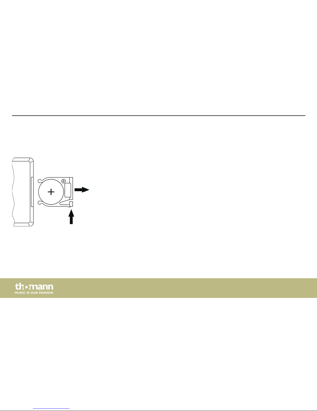
Press the lock of the battery holder to the centre of the housing and pull out the battery holder
like a drawer. Insert the battery. The battery is correct if the positive pole points to the housing
base of the remote control. Slide the battery holder back into the remote until it clicks into
place.
When shipping, the battery is already installed in the remote and protected against discharge
by a transparent plastic foil. Remove the plastic foil prior to first use.
Inserting the battery into the
remote control
Installation
LED effect
20
Page 21
5 Starting up
Create all connections while the device is off. Use the shortest possible high-quality cables for
all connections. Take care when running the cables to prevent tripping hazards.
Starting up
LED Derby ST
21
Page 22
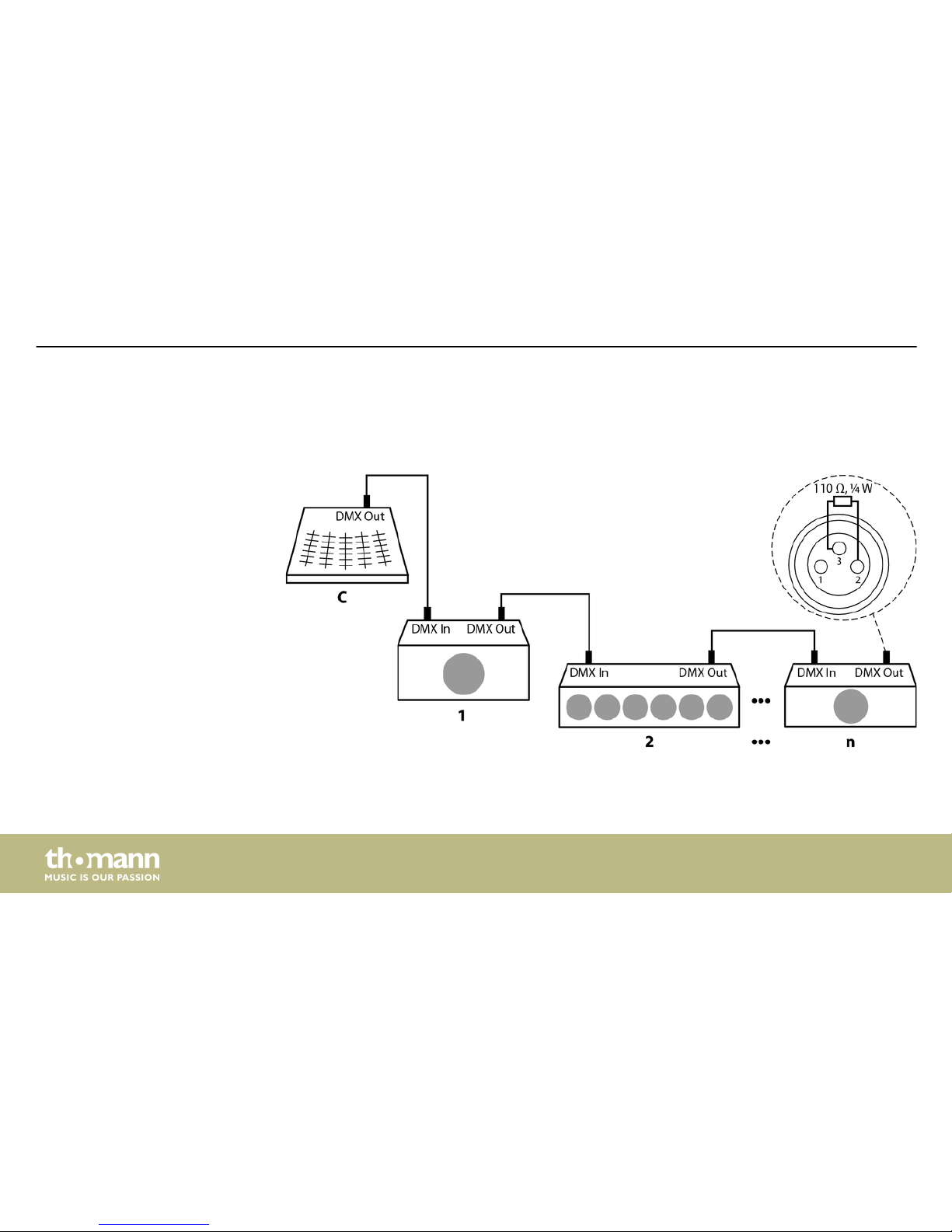
Connect the DMX input of the device to the DMX output of a DMX controller or another DMX
device. Connect the output of the first DMX device to the input of the second one, and so on
to form a daisy chain. Always ensure that the output of the last DMX device in the daisy chain
is terminated with a resistor (110 Ω, ¼ W).
Connections in DMX mode
Starting up
LED effect
22
Page 23
When you configure a group of devices in master/slave mode, the first unit will control the
other units for an automatic, sound-activated, synchronized show. This function is ideal when
you want to start a show immediately. Connect the DMX output of the master device to the
DMX input of the first slave device. Then connect the DMX output of the first slave device to
the DMX input of the second slave device and so on.
Connections in master/slave
mode
Starting up
LED Derby ST
23
Page 24
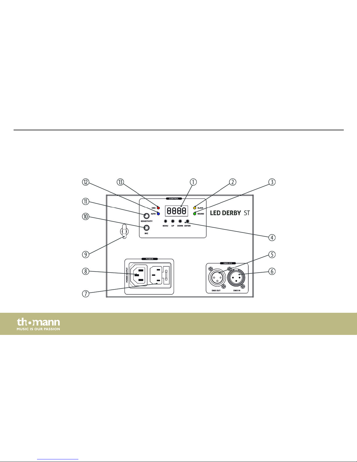
6 Connections and controls
Rear panel
Connections and controls
LED effect
24
Page 25
1 Display
2 [SLAVE]
Indicates that the device is in ‘Slave’ mode.
3 [SOUND]
Indicates that sound control (sound-to-light) is active.
4 Control buttons
[MENU]: Calls up the main menu or a submenu.
[UP]: Button to increase the displayed value by one.
[DOWN]: Button to decrease the displayed value by one.
[ENTER]: Confirms a selected value.
5 [DMX OUT]
DMX output.
Connections and controls
LED Derby ST
25
Page 26
6 [DMX IN]
DMX input.
7 IEC chassis plug with fuse holder for the power supply. Should the fuse have blown, disconnect the unit from the
power supply and replace the fuse with a new fuse of the same type.
8 [POWER OUTPUT]
Output socket to power another device with mains voltage.
9 Safety cable eyelet
10 [MIC]
Microphone for sound control.
11 [SENSITIVITY]
Rotary control to set the microphone sensitivity.
12 [AUTO]
Indicates that the device is in ‘Automatic’ mode.
13 [DMX]
Indicates that the device is receiving a DMX signal.
Connections and controls
LED effect
26
Page 27
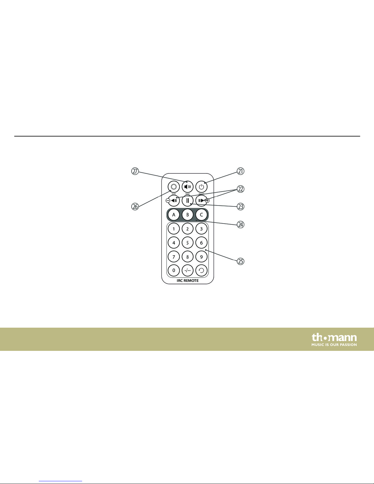
Remote control
Connections and controls
LED Derby ST
27
Page 28
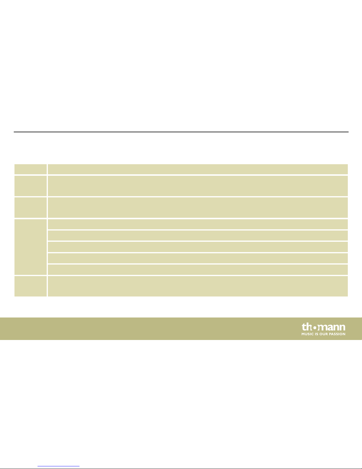
21 Main switch, turns the device on and off.
22 Changes colour, forwards or backwards.
23 Pause
24
n A: Turns the Derby effect of the four-colour LEDs on and off
n B: Selects a strobe program for the white LEDs
n C: Turns the strobe program for the white LEDs on and off
25 Numeric keys for setting the speed (0: slow, 9: fast)
26 Activates 'Automatic' mode (playback of preprogrammed automatic shows).
27 Activates 'Sound control' mode (playback of sound-controlled automatic shows).
Connections and controls
LED effect
28
Page 29
7 Operating
7.1 Starting the device
Connect the device to the power supply to start operation. After a few seconds the unit is
ready for use.
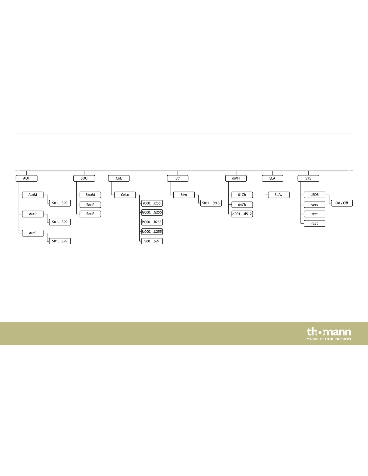
7.2 Main menu
Press [MENU] to activate the main menu. Use [UP] or [DOWN] to change the respectively dis‐
played value. When the display shows the desired value, press [ENTER].
Operating
LED Derby ST
29
Page 30
Press [MENU]. Then use [UP] or [DOWN] to select the menu item ‘dMH’ . Press [ENTER]. Select
either the 1-channel DMX mode (display ‘01Ch’ ), the 4-channel DMX mode (display ‘04Ch’) or
change to the input of the DMX address (display ‘dxxx’ ). Confirm with [ENTER].
If you have selected the menu item ‘dxxx’ , set the number of the first DMX channel used by
the device (DMX address). Use [UP] and [DOWN] to select a value between 1 and 512 (display
shows ‘A001’ …‘A512’).
When the display shows the desired value, press [ENTER] to confirm the selection and then
[MENU] to return to the parent menu.
Make sure that this number matches the configuration of your DMX controller.
Press [MENU]. Then use [UP] or [DOWN] to select the menu item ‘AUT’ . Press [ENTER]. Use [UP]
or [DOWN] to choose between ‘AutM’ (automatic show), ‘AutP’ (automatic program) or ‘AutF’
(strobe program). When the display shows the desired value, press [ENTER].
To set the speed, select a value between ‘S01’ (slow) and ‘S99’.
When the display shows the desired value, press [ENTER] to confirm the selection and then
[MENU] to return to the parent menu.
DMX address
Operating mode ‘Automatic’
Operating
LED effect
30
Page 31
Press [MENU]. Use [UP] or [DOWN] to select the menu item ‘SOU’ . Press [ENTER]. Use [UP] or
[DOWN] to choose between ‘SouM’ (sound-controlled automatic show), ‘SouP’ (sound-con‐
trolled automatic program) or ‘SouF’ (sound-controlled strobe program). When the display
shows the desired value, press [ENTER].
When the display shows the desired value, press [ENTER] to confirm the selection and then
[MENU] to return to the parent menu.
Press [MENU]. Use [UP] or [DOWN] to select the menu item ‘COL’ . Press [ENTER]. The display
shows ‘CoLo’ . Press [ENTER]. Use [UP] or [DOWN] to choose between ‘rxxx’ (red intensity),
‘Gxxx’ (green intensity), ‘bxxx’ (blue intensity), ‘Uxxx’ (white intensity) and ‘Sxx’ (speed of the
strobe effect). When the display shows the desired value, press [ENTER]. Set the corresponding
value with [UP] or [DOWN].
When the display shows the desired value, press [ENTER] to confirm the selection and then
[MENU] to return to the parent menu.
Press [MENU]. Use [UP] or [DOWN] to select the menu item ‘Str’ . Press [ENTER]. The display
shows ‘Stro’ . Press [ENTER]. Use [Up] and [Down] to select a strobe effect between ‘St01’ and
‘St18’ .
When the display shows the desired value, press [ENTER] to confirm the selection and then
[MENU] to return to the parent menu.
Sound control
Manual settings
Strobe effect
Operating
LED Derby ST
31
Page 32
Press [MENU]. Use [UP] or [DOWN] to select the menu item ‘SLA’ . Press [ENTER]. The display
shows ‘SLAv’ .
Confirm with [ENTER]. The slave device now exactly follows the specifications of the master
device. Then press [MENU] to return to the higher-level menu.
Press [MENU]. Use [UP] or [DOWN] to select the menu item ‘SYS’ . Press [ENTER]. Use [UP] or
[DOWN] to select one of the following menu items and then press [ENTER]:
n ‘LEDS’ : Choose between ‘On’ and ‘Off’ to turn all LEDs on or off
n ‘vers’ : The display shows the current software version used by the device.
n ‘test’ : A test program is started.
n ‘rESt’ : All device settings are reset.
n
Operating mode ‘Slave’
System menu
Operating
LED effect
32
Page 33
7.3 Menu overview
Operating
LED Derby ST
33
Page 34
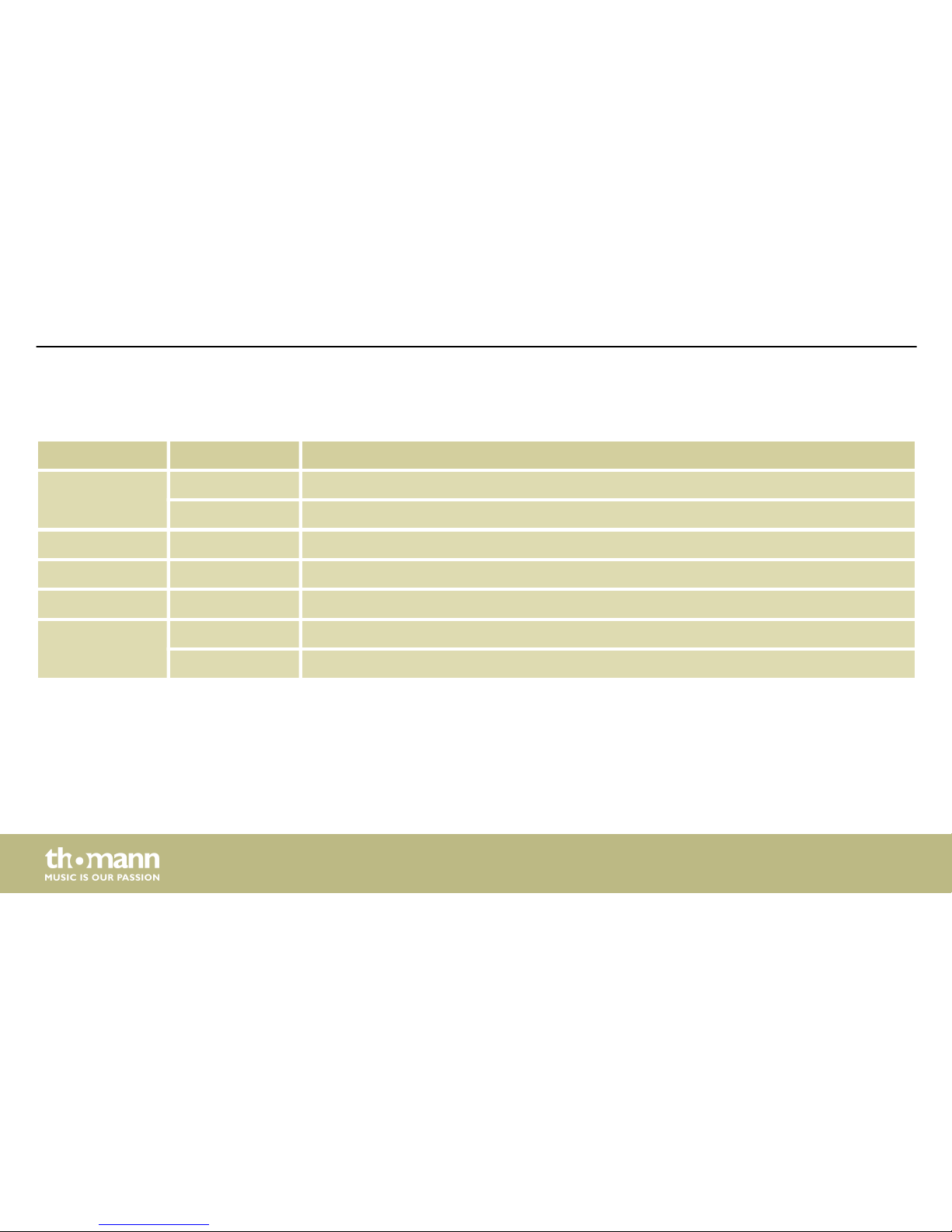
7.4 Functions in 1-channel DMX mode
Channel Value Function
1 0…9 No function
10…50 Auto show
51…90 Automatic program
91…130 Strobe program
131…170 Sound-controlled automatic show
171…210 Sound-controlled automatic program
211…255 Sound-controlled strobe program
Operating
LED effect
34
Page 35
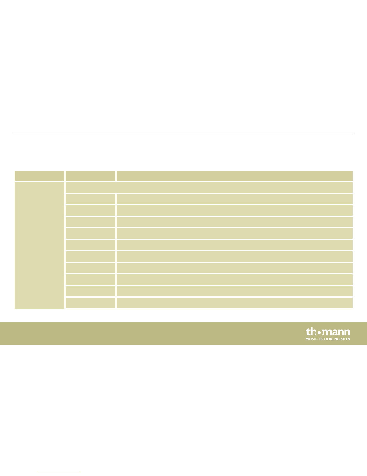
7.5 Functions in 4-channel DMX mode
Channel Value Function
1 Derby effect of the four-colour LEDs
0…5 No function
6…20 Red
21…35 Green
36…50 Blue
51…65 White
66…80 Red / green
81…95 Red / blue
96…110 Red / white
111…125 Green / blue
126…140 Green / white
Operating
LED Derby ST
35
Page 36
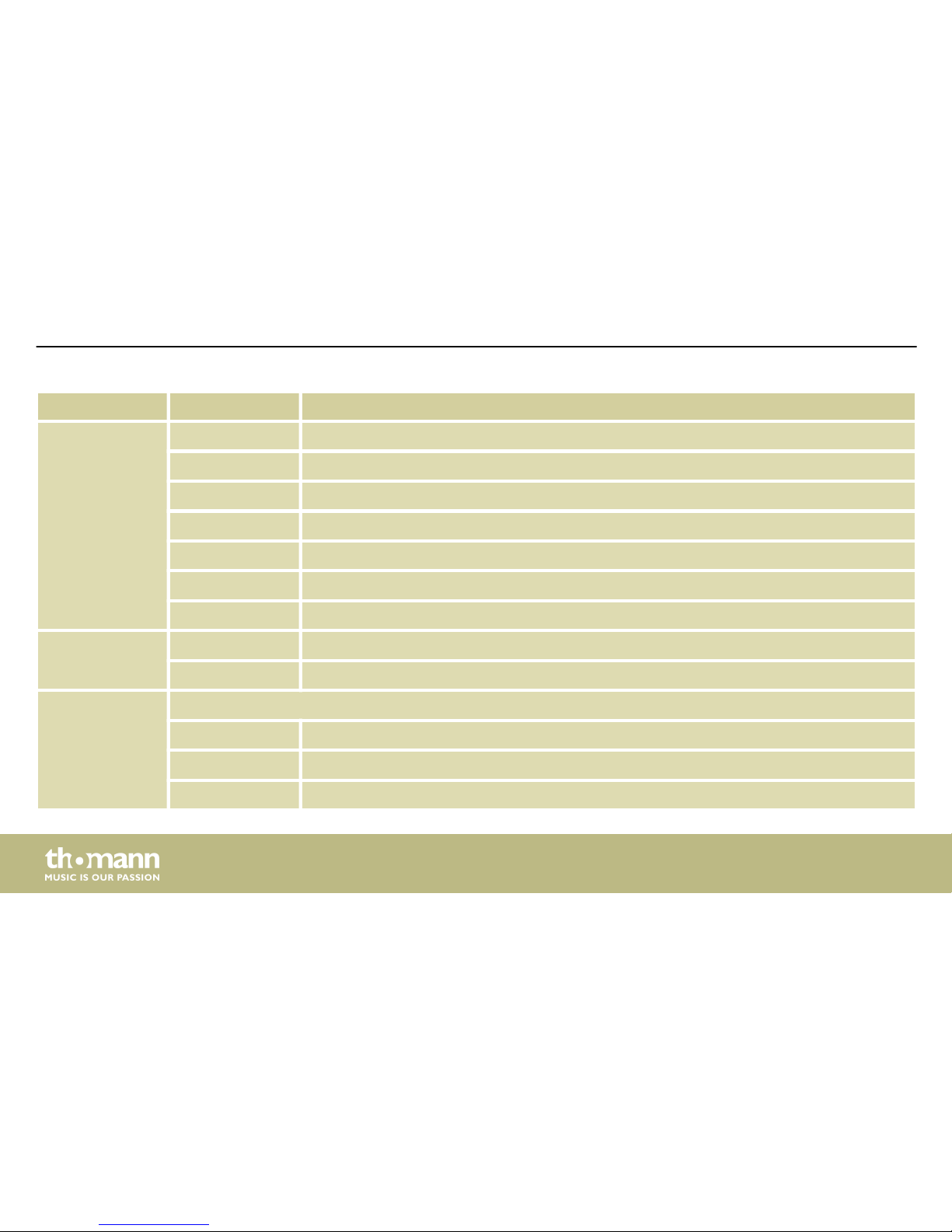
Channel Value Function
141…155 Blue / white
156…170 Red / green / blue
171…185 Red / green / white
186…200 Green / blue / white
201…215 Red / green / blue / white
216…230 Colour change 1
231…255 Colour change 2
2 0…5 No function
6…255 Strobe effect, increasing speed
3 Motor for moving light beams
0 No function
1…127 Fixed position (indexing)
128…255 Rotation
Operating
LED effect
36
Page 37
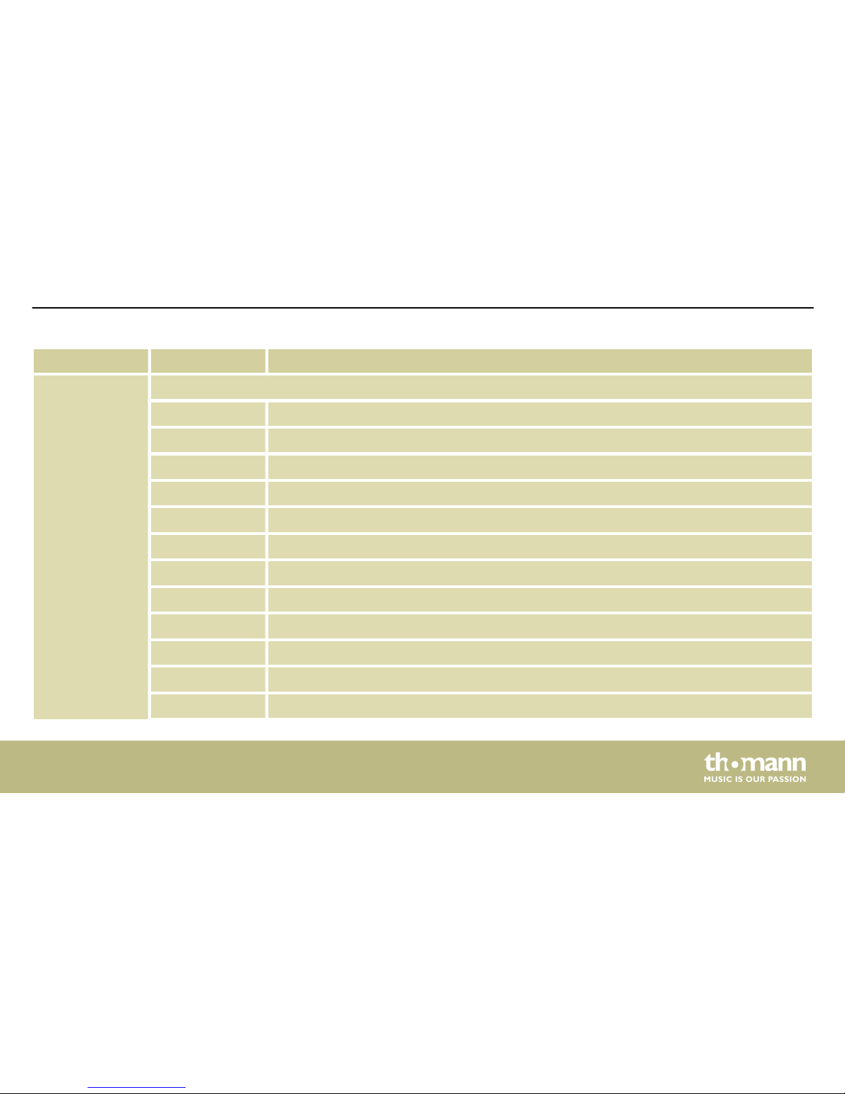
Channel Value Function
4 Strobe effect (white LEDs)
0…9 No function
10…19 Strobe pattern 1, increasing speed
20…29 Strobe pattern 2, increasing speed
30…39 Strobe pattern 3, increasing speed
40…49 Strobe pattern 4, increasing speed
50…59 Strobe pattern 5, increasing speed
60…69 Strobe pattern 6, increasing speed
70…79 Strobe pattern 7, increasing speed
80…89 Strobe pattern 8, increasing speed
90…99 Strobe pattern 9, increasing speed
100…109 Strobe pattern 10, increasing speed
110…119 Strobe pattern 11, increasing speed
Operating
LED Derby ST
37
Page 38
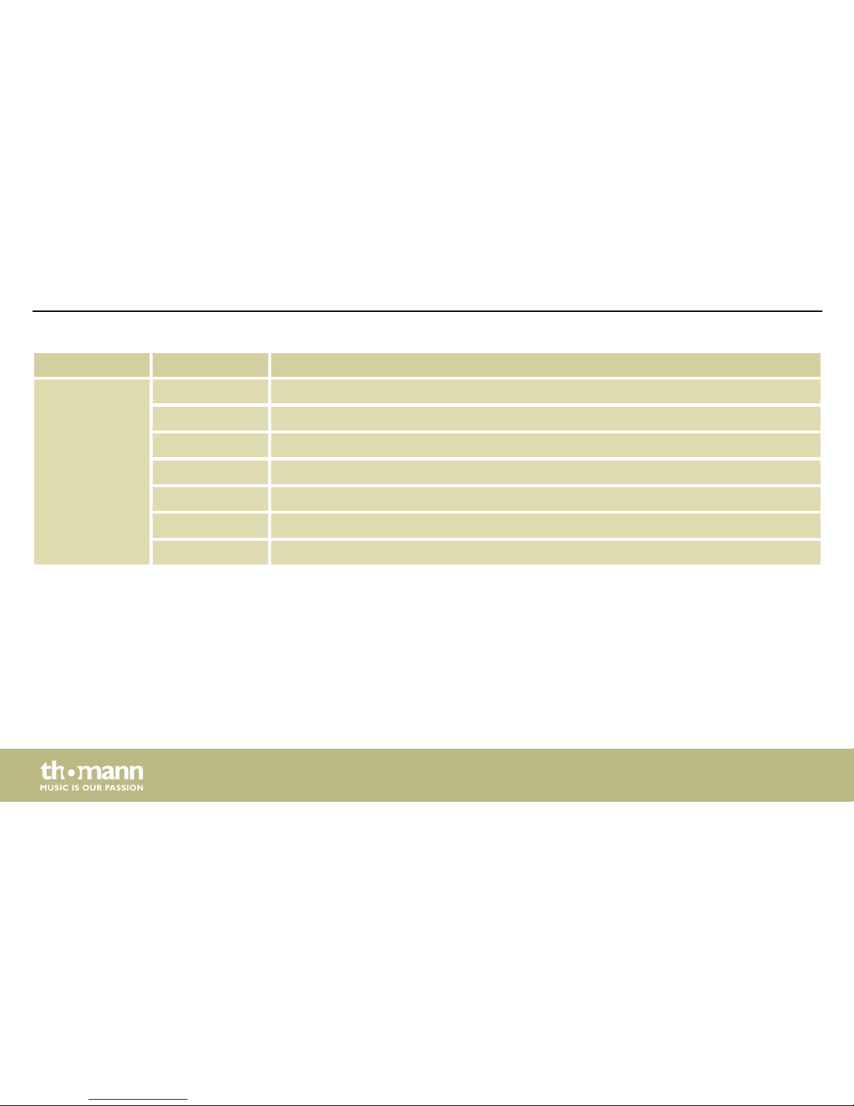
Channel Value Function
120…129 Strobe pattern 12, increasing speed
130…139 Strobe pattern 13, increasing speed
140…149 Strobe pattern 14, increasing speed
150…159 Strobe pattern 15, increasing speed
160…169 Strobe pattern 16, increasing speed
170…179 Strobe pattern 17, increasing speed
180…255 Full brightness, without strobe effect
Operating
LED effect
38
Page 39
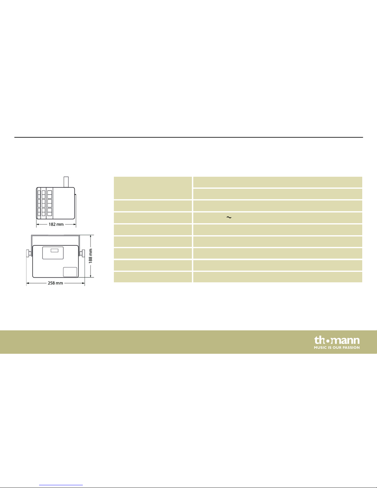
8 Technical specifications
LEDs 4 × RGBW-LEDs, each 3 W
16 white LEDs for strobe effects, each 0.5 W
Number of DMX channels 1 or 4, depending on operating mode
Operating voltage supply
100 – 240 V 50/60 Hz
Fuse 5 mm × 20 mm, 1 A, 250 V, slow blow
Power consumption 28 W
Protection class IP20
Dimensions (W × H × D) 258 mm × 188 mm × 182 mm
Weight 2.0 kg
Technical specifications
LED Derby ST
39
Page 40
9 Plug and connection assignments
This chapter will help you select the right cables and plugs to connect your valuable equip‐
ment so that a perfect light experience is guaranteed.
Please take our tips, because especially in ‘Sound & Light’ caution is indicated: Even if a plug
fits into a socket, the result of an incorrect connection may be a destroyed DMX controller, a
short circuit or ‘just’ a not working light show!
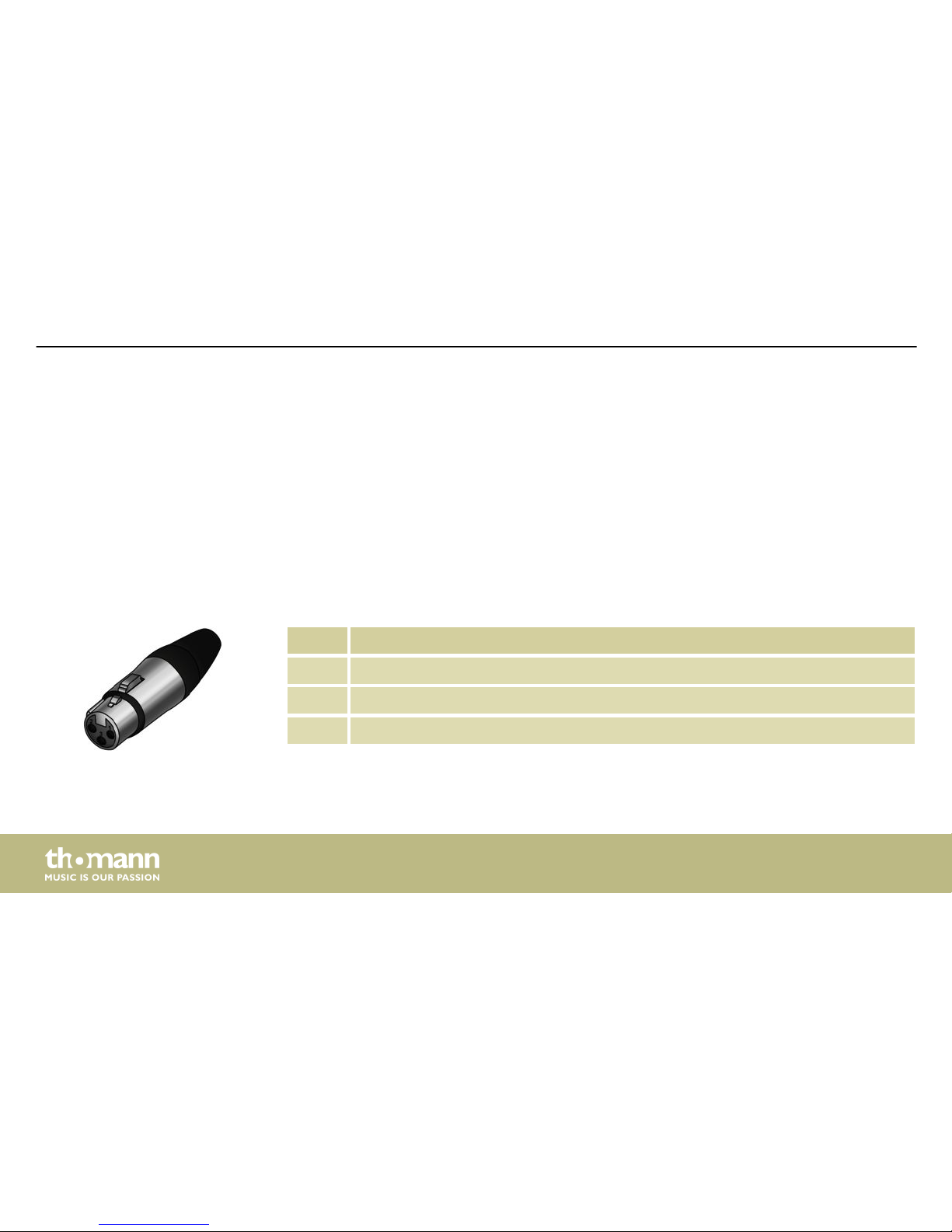
The unit offers a 3-pin XLR socket for DMX output and a 3-pin XLR plug for DMX input. Please
refer to the drawing and table below for the pin assignment of a suitable XLR plug.
Pin Configuration
1 Ground, shielding
2 Signal inverted (DMX–, ‘cold signal’)
3 Signal (DMX+, ‘hot signal’)
Introduction
DMX connections
Plug and connection assignments
LED effect
40
Page 41
10 Troubleshooting
NOTICE!
Possible data transmission errors
For error-free operation make use of dedicated DMX cables and do not use ordi‐
nary microphone cables.
Never connect the DMX input or output to audio devices such as mixers or ampli‐
fiers.
In the following we list a few common problems that may occur during operation. We give you
some suggestions for easy troubleshooting:
Troubleshooting
LED Derby ST
41
Page 42
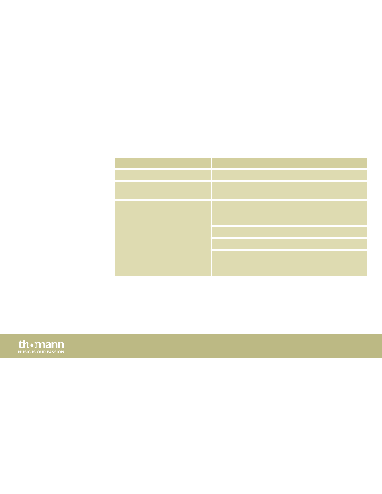
Symptom Remedy
The unit does not work, no light Check the mains connection.
Apparently no function despite
proper power supply
Check if the unit is in DMX mode or in ‘slave’ mode. If so,
check the unit in another mode.
No response to the DMX con‐
troller
1. Check whether the DMX controller is switched on.
Check the DMX connectors and cables for proper con‐
nection.
2. Check the address settings and the DMX polarity.
3. Try using another DMX controller.
4. Check to see if the DMX cables run near or alongside
to high voltage cables that may cause damage or inter‐
ference to DMX interface circuits.
If the procedures recommended above do not succeed, please contact our Service Center. You
can find the contact information at www.thomann.de.
Troubleshooting
LED effect
42
Page 43
11 Cleaning
Clean the optical lenses, that are accessible from the outside, regularly in order to optimize the
light output. The frequency of cleaning depends on the operating environment: wet, smoky or
particularly dirty surroundings can cause more accumulation of dirt on the optics of the
device.
n Clean with a soft cloth using our lamp and lens cleaner (item no. 280122).
n Always dry the parts carefully.
The fan grids of the device must be cleaned on a regular basis to remove dust and dirt. Before
cleaning, switch off the device and disconnect AC-powered devices from the mains. Use a lintfree damp cloth for cleaning. Never use solvents or alcohol for cleaning.
Optical lenses
Fan grids
Cleaning
LED Derby ST
43
Page 44
12 Protecting the environment
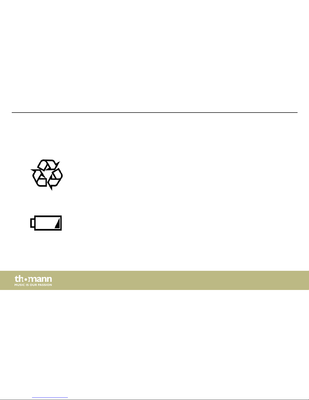
For the transport and protective packaging, environmentally friendly materials have been
chosen that can be supplied to normal recycling.
Ensure that plastic bags, packaging, etc. are properly disposed of.
Do not just dispose these materials with your normal household waste, but make sure that
they are fed to a recovery. Please follow the notes and markings on the packaging.
Batteries must not be disposed of as domestic waste or thrown into fire. Dispose of the bat‐
teries according to national or local regulations regarding hazardous waste. To protect the
environment, dispose of empty batteries at your retail store or at appropriate collection sites.
Disposal of the packaging mate‐
rial
Disposal of batteries
Protecting the environment
LED effect
44
Page 45
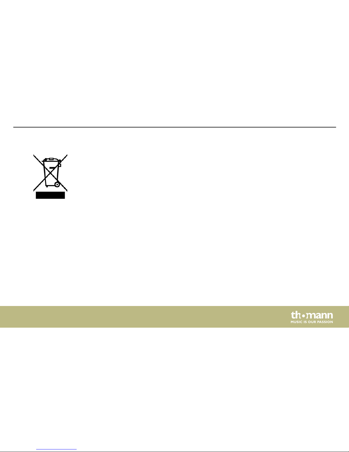
This product is subject to the European Waste Electrical and Electronic Equipment Directive
(WEEE). Do not dispose with your normal household waste.
Dispose this device through an approved waste disposal firm or through your local waste
facility. When discarding the device, comply with the rules and regulations that apply in your
country. If in doubt, consult your local waste disposal facility.
Disposal of your old device
Protecting the environment
LED Derby ST
45
Page 46
Notes
LED effect
46
Page 47

Page 48

Musikhaus Thomann · Hans-Thomann-Straße 1 · 96138 Burgebrach · Germany · www.thomann.de
 Loading...