

Page 1
mix 502, mix 802,
mix 1202FX
mixer
user manual
Page 2

Musikhaus Thomann
Thomann GmbH
Hans-Thomann-Straße 1
96138 Burgebrach
Germany
Telephone: +49 (0) 9546 9223-0
E-mail: info@thomann.de
Internet: www.thomann.de
08.02.2019, ID: 370662, 370664, 370666 (V3)
Page 3

Table of contents
Table of contents
1 General information................................................................................................................................. 4
1.1 Further information........................................................................................................................... 5
1.2 Notational conventions.................................................................................................................... 6
1.3 Symbols and signal words............................................................................................................... 6
2 Safety instructions..................................................................................................................................... 8
3 Features....................................................................................................................................................... 12
4 Installation and starting up................................................................................................................ 15
5 Connections and controls................................................................................................................... 16
6 Technical specications....................................................................................................................... 40
7 Plug and connection assignment.................................................................................................... 45
8 Protecting the environment.............................................................................................................. 49
mix 502, mix 802, mix 1202FX
3
Page 4

General information
1 General information
This user manual contains important information on the safe operation of the device. Read and
follow all safety notes and all instructions. Save this manual for future reference. Make sure
that it is available to all persons using this device. If you sell the device to another user, be sure
that they also receive this manual.
Our products and user manuals are subject to a process of continuous development. We there‐
fore reserve the right to make changes without notice. Please refer to the latest version of the
user manual which is ready for download under www.thomann.de.
mixer
4
Page 5
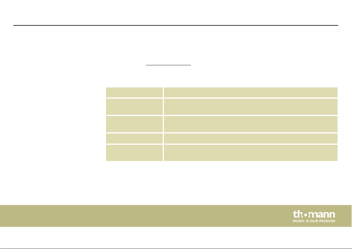
1.1 Further information
General information
On our website (www.thomann.de) you will nd lots of further information and details on the
following points:
Download This manual is also available as PDF le for you to download.
Keyword search
Online guides
Personal consultation For personal consultation please contact our technical hotline.
Service
Use the search function in the electronic version to nd the topics of
interest for you quickly.
Our online guides provide detailed information on technical basics
and terms.
If you have any problems with the device the customer service will
gladly assist you.
mix 502, mix 802, mix 1202FX
5
Page 6

General information
1.2 Notational conventions
This manual uses the following notational conventions:
Letterings
The letterings for connectors and controls are marked by square brackets and italics.
Examples: [VOLUME] control, [Mono] button.
1.3 Symbols and signal words
In this section you will nd an overview of the meaning of symbols and signal words that are
used in this manual.
6
mixer
Page 7
General information
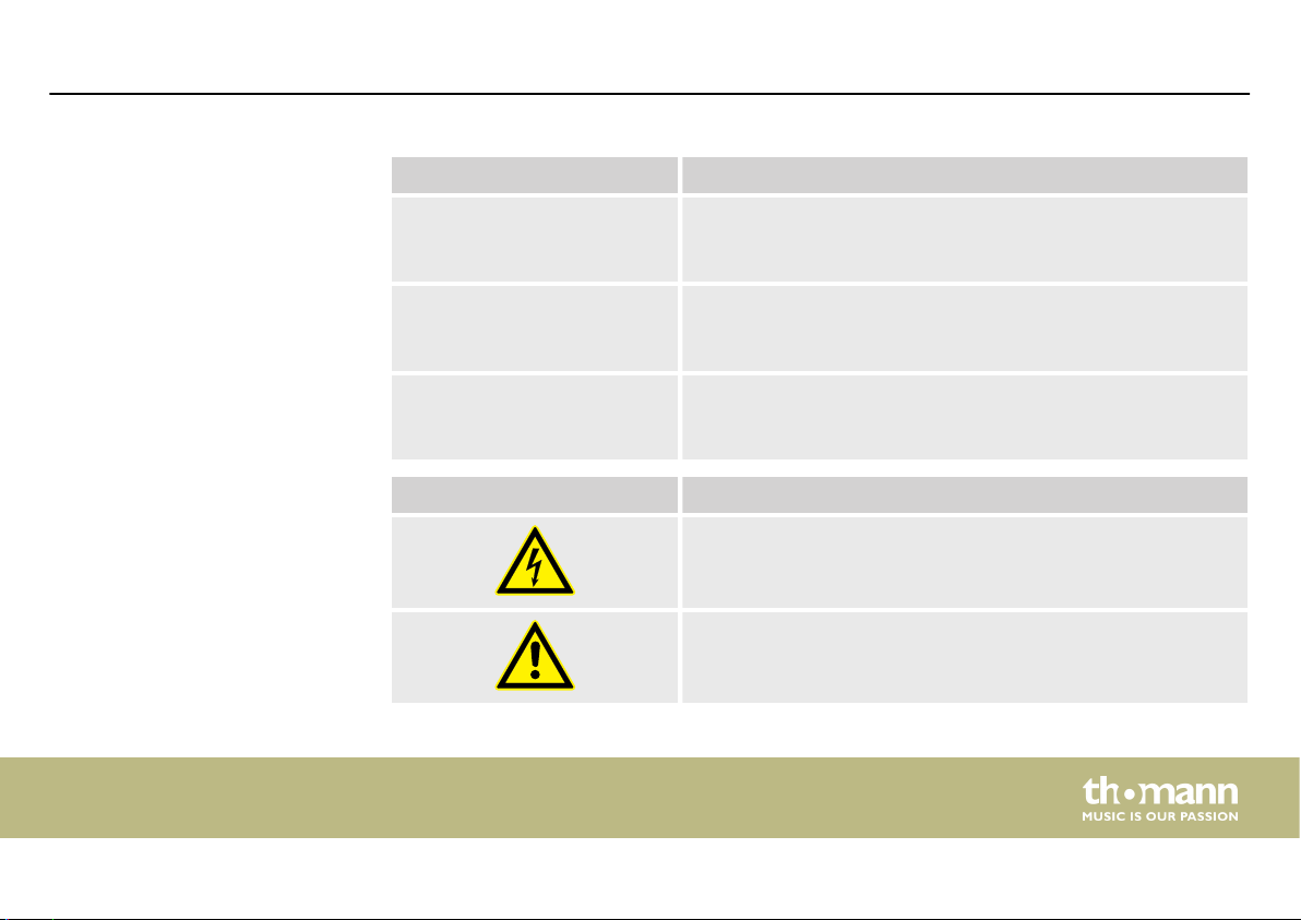
Signal word Meaning
DANGER! This combination of symbol and signal word indicates an
immediate dangerous situation that will result in death or
serious injury if it is not avoided.
CAUTION! This combination of symbol and signal word indicates a pos‐
sible dangerous situation that can result in minor injury if it
is not avoided.
NOTICE! This combination of symbol and signal word indicates a pos‐
sible dangerous situation that can result in material and
environmental damage if it is not avoided.
Warning signs Type of danger
Warning – high-voltage.
Warning – danger zone.
mix 502, mix 802, mix 1202FX
7
Page 8

Safety instructions
2 Safety instructions
Intended use
8
This device is intended to be used for amplication, mixing and playback of signals from
musical instruments and microphones. Use the device only as described in this user manual.
Any other use or use under other operating conditions is considered to be improper and may
result in personal injury or property damage. No liability will be assumed for damages resulting
from improper use.
This device may be used only by persons with sucient physical, sensorial, and intellectual
abilities and having corresponding knowledge and experience. Other persons may use this
device only if they are supervised or instructed by a person who is responsible for their safety.
mixer
Page 9
Safety
Safety instructions
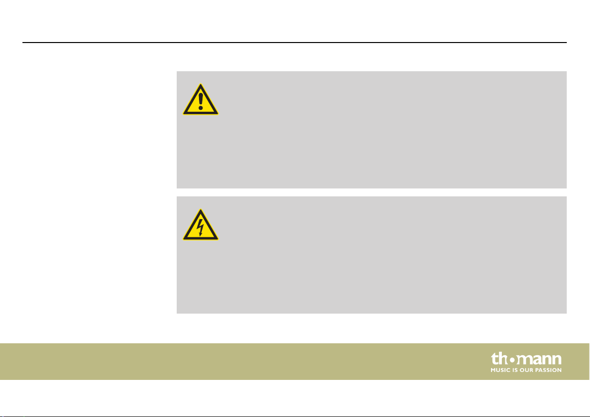
DANGER!
Danger for children
Ensure that plastic bags, packaging, etc. are disposed of properly and are not
within reach of babies and young children. Choking hazard!
Ensure that children do not detach any small parts (e.g. knobs or the like) from
the unit. They could swallow the pieces and choke!
Never let children unattended use electrical devices.
DANGER!
Electric shock caused by high voltages inside
Within the device there are areas where high voltages may be present. Never
remove any covers.
There are no user-serviceable parts inside.
Do not use the device if covers, protectors or optical components are missing or
damaged.
mix 502, mix 802, mix 1202FX
9
Page 10
Safety instructions
CAUTION!
Possible hearing damage
With loudspeakers or headphones connected, the device can produce volume
levels that may cause temporary or permanent hearing impairment.
Do not operate the device permanently at a high volume level. Decrease the
volume level immediately if you experience ringing in your ears or hearing
impairment.
NOTICE!
Risk of re
Do not block areas of ventilation. Do not install the device near any direct heat
source. Keep the device away from naked ames.
10
mixer
Page 11

Safety instructions
NOTICE!
Operating conditions
This device has been designed for indoor use only. To prevent damage, never
expose the device to any liquid or moisture. Avoid direct sunlight, heavy dirt, and
strong vibrations.
NOTICE!
External power supply
The device is powered by an external power supply. Before connecting the
external power supply, ensure that the input voltage (AC outlet) matches the
voltage rating of the device and that the AC outlet is protected by a residual cur‐
rent circuit breaker. Failure to do so could result in damage to the device and pos‐
sibly the user.
Unplug the external power supply before electrical storms occur and when the
device is unused for long periods of time to reduce the risk of electric shock or
re.
mix 502, mix 802, mix 1202FX
11
Page 12

Features
3 Features
mix 502
12
n 5-channel mixer
n 1 × mono input (MIC, line)
n 2 × stereo input (line)
n 1 × master output (stereo)
n 1 × stereo RCA audio input
n 1 × stereo RCA audio output
n 2-band equalizer (mono channel)
n Pan control
n 48 V phantom power
n Headphones output separately adjustable
n Suitable power supply included
mixer
Page 13

Features
mix 802
n 8-channel mixer
n 4 × mono input (MIC, line)
n 2 × stereo input (line)
n 1 × master output (stereo)
n 1 × control room output
n 1 × stereo RCA audio input
n 1 × stereo RCA audio output
n 3-band equalizer
n Pan control
n 48 V phantom power
n Headphones output separately adjustable
n Suitable power supply included
mix 502, mix 802, mix 1202FX
13
Page 14

Features
mix 1202fx
n 12-channel FX mixer
n 4 × mono input (MIC, line)
n 4 × stereo input (line)
n 1 × master output (stereo)
n 1 × control room output
n 1 × stereo RCA audio input
n 1 × stereo RCA audio output
n 3-band equalizer
n Pan control
n 48 V phantom power
n Headphones output separately adjustable
n Suitable power supply included
mixer
14
Page 15

4 Installation and starting up
Unpack and check carefully there is no transportation damage before using the unit. Keep the
equipment packaging. To fully protect the product against vibration, dust and moisture during
transportation or storage use the original packaging or your own packaging material suitable
for transport or storage, respectively.
Only use the supplied power adapter. The connector for the power supply is located on the
rear panel.
The device has no main switch. Supply voltage is available as soon as you connect the device
to the power grid via the power supply.
Before connecting the supply voltage and before connecting or disconnecting audio cables,
set all volume controls of the unit to zero to avoid damage to the connected speakers and
devices.
Installation and starting up
mix 502, mix 802, mix 1202FX
15
Page 16
Connections and controls
5 Connections and controls
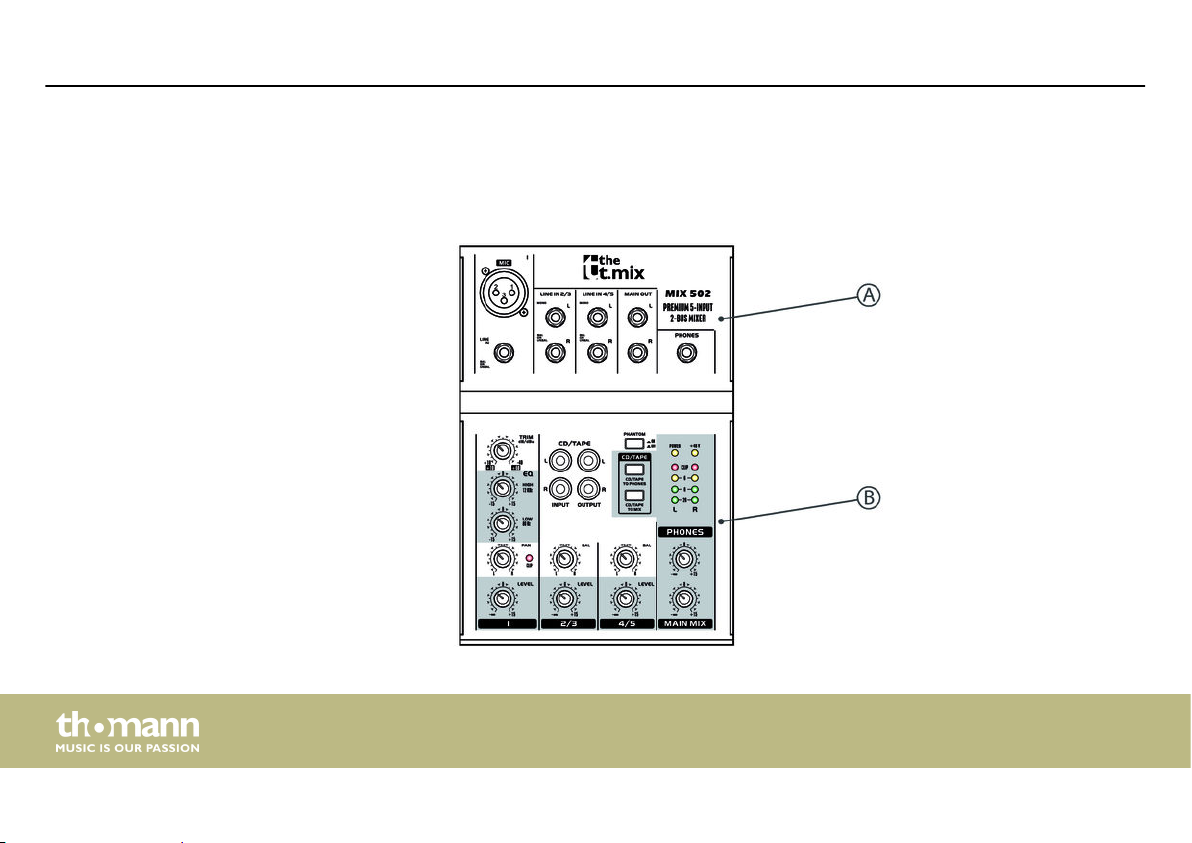
mix 502 – overview
16
mixer
Page 17

mix 502 – partial view A
Connections and controls
mix 502, mix 802, mix 1202FX
17
Page 18

Connections and controls
1 [MIC] | [LINE IN]
Mono input channel with XLR input socket [MIC] and 1/4" phone socket [LINE IN].
2 [LINE IN X/X]
Stereo input channels, each with 2 × 1/4" phone sockets (L/R) to connect a stereo source (keyboard, drum module, etc.) or
an instrument (guitar, bass). Always use the input L (mono jack) for mono operation on these channels.
3 [MAIN OUT]
Mono output with 2 × 1/4" phone sockets (unbalanced) for connecting a PA system, a PC or powered speakers. The main
signal is present with 0 dBu on this output, volume is controlled by rotary control [MAIN MIX].
4 [PHONES]
Headphones output, designed as 1/4" phone socket.
18
mixer
Page 19

mix 502 – partial view B
Connections and controls
mix 502, mix 802, mix 1202FX
19
Page 20

Connections and controls
5 [CD/TAPE INPUT]
Stereo RCA input sockets for feeding the signal from a CD or MP3 player.
[CD/TAPE OUTPUT]
Stereo RCA output sockets for connecting an external recording device.
6 [PHANTOM]
Switch to enable 48 V phantom power for condenser microphones connected to the XLR socket of the mono input
channel. When pressed, phantom power is present and the LED [+48V] lights yellow.
Disable 48 V phantom power before connecting a microphone. Set all volume controls of the device to zero before ena‐
bling 48 V phantom power.
7 [CD/TAPE TO PHONES]
Press [CD/TAPE TO PHONES] to route the [CD/TAPE INPUT] input signal to the headphones output.
[CD/TAPE TO MIX]
Press [CD/TAPE TO MIX] to route the [CD/TAPE INPUT] input signal to the main mix. Volume is then controlled via rotary
control [MAIN MIX].
20
mixer
Page 21

Connections and controls
8 Indicator LEDs:
[POWER]: lights yellow when operating voltage is present.
[+48V]: lights yellow when 48 V phantom power is present.
[CLIP]: lights red when the output signal is clipping. The associated LED chain shows the output signal level.
9 [PHONES] | [MAIN MIX]
Rotary controls for adjusting the volume of the headphones output [PHONES] and the output signal [MAIN MIX] of the
device.
The headphones output and [MAIN MIX] can only be adjusted together.
mix 502, mix 802, mix 1202FX
21
Page 22

Connections and controls
10 Stereo channels 5 … 8
[BAL]: Rotary volume for stereo balance setting.
[LEVEL]: Rotary control for setting the output signal volume.
11 Mono channel 1
[TRIM]: Rotary control to adjust the gain.
[EQ]: Rotary controls for adjusting treble and bass.
[PAN]: Rotary control to position the signal within the stereo panorama.
[LEVEL]: Rotary control for adjusting the output signal volume.
22
mixer
Page 23

mix 802 – overview
Connections and controls
mix 502, mix 802, mix 1202FX
23
Page 24

Connections and controls
mix 802 – partial view A
24
mixer
Page 25

Connections and controls
1 [MIC] | [LINE IN]
Mono input channels with XLR input socket [MIC] and 1/4" phone socket [LINE IN] to connect a microphone, with rotary
control [TRIM] for channel gain.
2 [LINE IN X/X]
Stereo input channels, each with 2 × 1/4" phone sockets (L/R) to connect a stereo source (keyboard, drum module, etc.) or
an instrument (guitar, bass). Always use the input L (mono jack) for mono operation on these channels.
3 [MAIN OUT]
Mono output with 2 × 1/4" phone sockets (unbalanced) for connecting a PA system, a PC or powered speakers. The main
signal is present with 0 dBu on this output, volume is controlled by rotary control [MAIN MIX].
4 [STEREO AUX RETURN]
1/4" input sockets for the processed signal of a looped-in eects device.
5 [CTRL ROOM OUT]
1/4" output sockets for connecting stage or near-eld monitors.
mix 502, mix 802, mix 1202FX
25
Page 26

Connections and controls
6 [FX SEND]
1/4" output socket to feed the signal to an external eects device.
7 [PHONES]
Headphones output, designed as 1/4" phone socket.
26
mixer
Page 27

mix 802 – partial view B
Connections and controls
mix 502, mix 802, mix 1202FX
27
Page 28

Connections and controls
8 [CD/TAPE TO PHONES]
Press [CD/TAPE TO PHONES] to route the [CD/TAPE INPUT] input signal to the headphones output. Then the signal is not
present on the main output.
[CD/TAPE TO MIX]
Press [CD/TAPE TO MIX] to route the [CD/TAPE INPUT] input signal to the main mix. Volume is then controlled via rotary
control [MAIN MIX].
9 [CD/TAPE INPUT]
Stereo RCA input sockets for feeding the signal from a CD or MP3 player.
[CD/TAPE OUTPUT]
Stereo RCA output sockets for connecting an external recording device.
10 [MAIN SECTION]
Indicator LEDs:
[POWER]: lights yellow when operating voltage is present.
[+48V]: lights yellow when 48 V phantom power is present.
[CLIP]: lights red when the output signal is clipping. The associated LED chain shows the output signal level.
28
mixer
Page 29

Connections and controls
[MAIN MIX]: Rotary control for adjusting the volume of the output signal.
[PHONES/CTRL ROOM]: Rotary control for adjusting the volume of the headphones output or the connected stage or near-
eld monitors, respectively.
[PHANTOM]: Switch to enable 48 V phantom power for condenser microphones connected to the XLR socket of a mono
input channel. When pressed, phantom power is present and the LED [+48V] lights yellow.
Disable 48 V phantom power before connecting a microphone. Set all volume controls of the device to zero before ena‐
bling 48 V phantom power.
[AUX FX RETURN]: Rotary control to adjust the eect volume of the overall volume.
mix 502, mix 802, mix 1202FX
29
Page 30

Connections and controls
11 Mono channels 1 … 4
[EQ]: Rotary controls for adjusting treble, mids and bass.
[FX]: Rotary control to adjust the channel eects ratio to the overall volume.
[PAN]: Rotary control to position the signal within the stereo panorama.
[LEVEL]: Rotary control for adjusting the output signal volume.
12 Stereo channels 5 … 8
[EQ]: Rotary controls for adjusting treble, mids and bass.
[FX]: Rotary control to adjust the channel eects ratio to the overall volume.
[PAN]: Rotary control to position the signal within the stereo panorama.
[LEVEL]: Rotary control for adjusting the output signal volume.
30
mixer
Page 31

mix 1202FX – overview
Connections and controls
mix 502, mix 802, mix 1202FX
31
Page 32

Connections and controls
mix 1202FX – partial view A
32
mixer
Page 33

Connections and controls
1 [MIC] | [LINE IN]
Mono input channels with XLR input socket [MIC] and 1/4" phone socket [LINE IN] to connect a microphone, with rotary
control [TRIM] for channel gain.
2 [LINE IN X/X]
Stereo input channels, each with 2 × 1/4" phone sockets (L/R) to connect a stereo source (keyboard, drum module, etc.) or
an instrument (guitar, bass). Always use the input L (mono jack) for mono operation on these channels.
3 [MAIN OUT]
Mono output with 2 × 1/4" phone sockets (unbalanced) for connecting a PA system, a PC or powered speakers. The main
signal is present with 0 dBu on this output, volume is controlled by the main fader.
4 [CTRL ROOM OUT]
1/4" output sockets for connecting stage or near-eld monitors.
5 [FX SEND]
1/4" output socket to connect an external eects device.
6 [PHONES]
Headphones output, designed as 1/4" phone socket.
mix 502, mix 802, mix 1202FX
33
Page 34

Connections and controls
mix 1202FX – partial view B
34
mixer
Page 35

Connections and controls
7 [CD/TAPE INPUT]
Stereo RCA input sockets for feeding the signal from a CD or MP3 player.
[CD/TAPE OUTPUT]
Stereo RCA output sockets for connecting an external recording device.
8 [CD/TAPE TO PHONES]
Press [CD/TAPE TO PHONES] to route the [CD/TAPE INPUT] input signal to the headphones output. Then the signal is not
present on the main output.
[CD/TAPE TO MIX]
Press [CD/TAPE TO MIX] to route the [CD/TAPE INPUT] input signal to the main mix. Volume is then controlled via rotary
control [MAIN MIX].
9 [FX TO CTRL]
Press [FX TO CTRL] to route the processed signal to the stage or near-eld monitors.
mix 502, mix 802, mix 1202FX
35
Page 36

Connections and controls
10 [PHANTOM]
Switch to enable 48 V phantom power for condenser microphones connected to the XLR socket of a mono input channel.
When pressed, phantom power is present and the LED [+48V] lights yellow.
Disable 48 V phantom power before connecting a microphone. Set all volume controls of the device to zero before ena‐
bling 48 V phantom power.
11 [PHONES]: Rotary control for adjusting the volume of the headphones output.
[FX TO MAIN]: Rotary control to adjust the eect volume of the overall volume.
12 Display to indicate the selected eect.
13 [PROGRAM (PUSH)]
Eects selector switch. The number of the selected eect is ashing in the display. Press the selector switch to conrm the
selection and to enable the eect.
14 [MAIN MIX]
Indicator LEDs:
[POWER]: lights yellow when operating voltage is present.
[+48V]: lights yellow when 48 V phantom power is present.
[CLIP]: lights red when the output signal is clipping. The associated LED chain shows the output signal level.
36
mixer
Page 37

Fader for adjusting the volume of the output signal.
15 Stereo channels 5 … 8
[FX]: Rotary control to adjust the channel eects ratio to the overall volume.
[BAL]: Rotary control to position the signal within the stereo panorama.
[LEVEL]: Rotary control for adjusting the output signal volume.
[+4/–10]: Toggle switch for input sensitivity +4 dBu (studio level) or –10 dBu (home recording level).
16 Mono channels 1 … 4
[EQ]: Rotary controls for adjusting treble, mids and bass.
[FX]: Rotary control to adjust the channel eects ratio to the overall volume.
[PAN]: Rotary control to position the signal within the stereo panorama.
[LEVEL]: Rotary control for adjusting the output signal volume.
[LOW CUT]: Switch to enable the high pass lter.
Connections and controls
mix 502, mix 802, mix 1202FX
37
Page 38

Connections and controls
Connection pattern – club gig
38
mixer
Page 39

Connection pattern – PC home
recording
Connections and controls
mix 502, mix 802, mix 1202FX
39
Page 40

Technical specications
6 Technical specications
Input connections Mono Type 1/4" jack socket, balanced
Level max. +12 dBu @ +10 dB Gain
Impedance 2.6 kΩ
Signal gain +10 … +60 dB
Line Type 1/4" jack socket, balanced
Level max. +22 dBu @ +0 dB Gain
Impedance 20 kΩ, balanced
10 kΩ, unbalanced
Signal gain -10 … +40 dB
Stereo Type Pair of RCA sockets
Level max. +22 dBu
Impedance 20 kΩ
40
mixer
Page 41

Microphone Type XLR chassis socket, 3-pin
Output connections Main Type 1/4" jack socket (unbalanced)
Level max. +28 dBu
Impedance 120 Ω, unbalanced
Aux Type 1/4" jack socket
Level max. +22 dBu
Impedance 20 kΩ
CTRL Type 1/4" jack socket
Level max. +22 dBu
Impedance 120 Ω
Phones Level max. +25 dBu
Frequency range Mono <10 Hz … 150 kHz (–1 dB)
<10 Hz … 200 kHz (–3 dB)
Technical specications
Line <10 Hz … 90 kHz (0 dB / –1 dB)
mix 502, mix 802, mix 1202FX
41
Page 42

Technical specications
<10 Hz … 160 kHz (0 dB / -3 dB)
Stereo <10 Hz … 90 kHz (0 dB / –1 dB)
<10 Hz … 160 kHz (0 dB / -3 dB)
Signal-to-noise ratio 110 dB / 112 dB, A-weighted
Total harmonic distortion (THD) 0.005 % / 0.004 %, A-weighted
Equalizer Range HIGH 12 kHz / 15 dB
Range MID 2.5 kHz / 15 dB
Range LOW 80 Hz / 15 dB
Phantom power 48 V
Power consumption t.mix 502 13 W
t.mix 802 17 W
t.mix 1202FX 23 W
Supply voltage
Dimensions (W × H × D) t.mix 502 125 mm × 50 mm × 195 mm
230 V 50 Hz
mixer
42
Page 43

t.mix 802 245 mm × 60 mm × 240 mm
t.mix 1202FX 270 mm × 60 mm × 240 mm
Weight t.mix 502 0.7 kg
t.mix 802 1.5 kg
t.mix 1202FX 1.7 kg
Technical specications
Ambient conditions Temperature
range
Relative humidity 50 %, non condensing
mix 502, mix 802, mix 1202FX
0 °C…40 °C
43
Page 44

Technical specications
Further information
t.mix mix 502 t.mix mix 802 t.mix mix 1202FX
Built-in eects unit No No Yes
Suitable for 19" No No No
Microphone channels 1 4 4
Number of stereo inputs 2 2 4
Number of buses 0 1 (post) 1 (post)
Phantom powering Yes Yes Yes
Built-in power supply No No No
Parametric No No No
Digital interface No No No
44
mixer
Page 45

7 Plug and connection assignment
Plug and connection assignment
Introduction
Balanced and unbalanced trans‐
mission
This chapter will help you select the right cables and plugs to connect your valuable equip‐
ment in such a way that a perfect sound experience is ensured.
Please note these advices, because especially in ‘Sound & Light’ caution is indicated: Even if a
plug ts into the socket, an incorrect connection may result in a destroyed power amp, a short
circuit or ‘just’ in poor transmission quality!
Unbalanced transmission is mainly used in semi-professional environment and in hi use.
Instrument cables with two conductors (one core plus shielding) are typical representatives of
the unbalanced transmission. One conductor is ground and shielding while the signal is trans‐
mitted through the core.
Unbalanced transmission is susceptible to electromagnetic interference, especially at low
levels, such as microphone signals and when using long cables.
In a professional environment, therefore, the balanced transmission is preferred, because this
enables an undisturbed transmission of signals over long distances. In addition to the conduc‐
tors ‘Ground’ and ‘Signal’, in a balanced transmission a second core is added. This also transfers
the signal, but phase-shifted by 180°.
mix 502, mix 802, mix 1202FX
45
Page 46

Plug and connection assignment
1/4" TS phone plug (mono,
unbalanced)
1/4" TRS phone plug (mono, bal‐
anced)
Since the interference aects both cores equally, by subtracting the phase-shifted signals, the
interfering signal is completely neutralized. The result is a pure signal without any noise inter‐
ference.
1 Signal
2 Ground, shielding
1 Signal (in phase, +)
2 Signal (out of phase, –)
3 Ground
46
mixer
Page 47

1/4" TRS phone plug (stereo,
unbalanced)
XLR plug (balanced)
Plug and connection assignment
1 Signal (left)
2 Signal (right)
3 Ground
1 Ground, shielding
2 Signal (in phase, +)
3 Signal (out of phase, –)
4 Shielding on plug housing (option)
mix 502, mix 802, mix 1202FX
47
Page 48

Plug and connection assignment
XLR plug (unbalanced)
1 Ground, shielding
2 Signal
3 Bridged to pin 1
RCA connection
48
Drawing and table indicate the pin assignment of an RCA plug.
1 Signal
2 Ground, shielding
mixer
Page 49

8 Protecting the environment
Disposal of the packaging mate‐
rial
For the transport and protective packaging, environmentally friendly materials have been
chosen that can be supplied to normal recycling.
Ensure that plastic bags, packaging, etc. are properly disposed of.
Do not just dispose of these materials with your normal household waste, but make sure that
they are collected for recycling. Please follow the notes and markings on the packaging.
Disposal of your old device
This product is subject to the European Waste Electrical and Electronic Equipment Directive
(WEEE) in its currently valid version. Do not dispose with your normal household waste.
Dispose of this device through an approved waste disposal rm or through your local waste
facility. When discarding the device, comply with the rules and regulations that apply in your
country. If in doubt, consult your local waste disposal facility.
Protecting the environment
mix 502, mix 802, mix 1202FX
49
Page 50

Notes
50
mixer
Page 51

Page 52

Musikhaus Thomann · Hans-Thomann-Straße 1 · 96138 Burgebrach · Germany · www.thomann.de
 Loading...