

Page 1
MBA120W MKII HTPT
battery-powered
speaker
user manual
Page 2

Musikhaus Thomann
Thomann GmbH
Hans-Thomann-Straße 1
96138 Burgebrach
Germany
Telephone: +49 (0) 9546 9223-0
E-mail: info@thomann.de
Internet: www.thomann.de
10.03.2021, ID: 490318 (V2)
Page 3

Table of contents
Table of contents
1 General information................................................................................................................................. 5
1.1 Further information........................................................................................................................... 6
1.2 Notational conventions.................................................................................................................... 7
1.3 Symbols and signal words............................................................................................................... 8
2 Safety instructions.................................................................................................................................. 10
3 Features....................................................................................................................................................... 14
4 Installation.................................................................................................................................................. 16
4.1 Speaker................................................................................................................................................ 17
4.2 Remote control................................................................................................................................. 19
4.3 UHF handheld transmitter............................................................................................................ 20
4.4 UHF pocket transmitter................................................................................................................. 21
5 Connections and operating elements........................................................................................... 22
5.1 UHF receiver....................................................................................................................................... 24
5.2 Speaker................................................................................................................................................ 27
5.3 Remote control................................................................................................................................. 40
MBA120W MKII HTPT
3
Page 4

Table of contents
5.4 UHF handheld transmitter............................................................................................................ 44
5.5 UHF pocket transmitter................................................................................................................. 47
6 Technical specications....................................................................................................................... 50
6.1 Speaker................................................................................................................................................ 50
6.2 UHF receiver....................................................................................................................................... 53
6.3 UHF handheld transmitter............................................................................................................ 54
6.4 UHF pocket transmitter................................................................................................................. 55
6.5 Headset................................................................................................................................................ 57
7 Plug and connection assignment.................................................................................................... 59
8 Cleaning....................................................................................................................................................... 63
9 Protecting the environment.............................................................................................................. 64
battery-powered speaker
4
Page 5

1 General information
This user manual contains important information on the safe operation of the device. Read and
follow all safety notes and all instructions. Save this manual for future reference. Make sure
that it is available to all persons using this device. If you sell the device to another user, be sure
that they also receive this manual.
Our products and user manuals are subject to a process of continuous development. We there‐
fore reserve the right to make changes without notice. Please refer to the latest version of the
user manual which is ready for download under www.thomann.de.
General information
MBA120W MKII HTPT
5
Page 6
General information
1.1 Further information
On our website (www.thomann.de) you will nd lots of further information and details on the
following points:
Download This manual is also available as PDF le for you to download.
Keyword search
Online guides
Personal consultation For personal consultation please contact our technical hotline.
Service
Use the search function in the electronic version to nd the topics of
interest for you quickly.
Our online guides provide detailed information on technical basics
and terms.
If you have any problems with the device the customer service will
gladly assist you.
battery-powered speaker
6
Page 7

1.2 Notational conventions
This manual uses the following notational conventions:
General information
Letterings
Displays
Cross-references
The letterings for connectors and controls are marked by square brackets and italics.
Examples: [VOLUME] control, [Mono] button.
Texts and values displayed on the device are marked by quotation marks and italics.
Examples: ‘24ch’ , ‘OFF’.
References to other locations in this manual are identied by an arrow and the specied page
number. In the electronic version of the manual, you can click the cross-reference to jump to
the specied location.
Example: See Ä ‘Cross-references’ on page 7.
MBA120W MKII HTPT
7
Page 8

General information
1.3 Symbols and signal words
In this section you will nd an overview of the meaning of symbols and signal words that are
used in this manual.
Signal word Meaning
DANGER! This combination of symbol and signal word indicates an
CAUTION! This combination of symbol and signal word indicates a pos‐
NOTICE! This combination of symbol and signal word indicates a pos‐
immediate dangerous situation that will result in death or
serious injury if it is not avoided.
sible dangerous situation that can result in minor injury if it
is not avoided.
sible dangerous situation that can result in material and
environmental damage if it is not avoided.
battery-powered speaker
8
Page 9
Warning signs Type of danger
Warning – high-voltage.
Warning – danger zone.
General information
MBA120W MKII HTPT
9
Page 10

Safety instructions
2 Safety instructions
Intended use
Safety
DANGER!
Danger for children
Ensure that plastic bags, packaging, etc. are disposed of properly and are not within reach of babies and young children. Choking
hazard! Ensure that children do not detach any small parts (e.g. knobs or the like) from the unit. They could swallow the pieces and
choke! Never let children unattended use electrical devices.
10
This device is designed for sound reinforcement. Use the device only as described in this user
manual. Any other use or use under other operating conditions is considered to be improper
and may result in personal injury or property damage. No liability will be assumed for damages
resulting from improper use.
This device may be used only by persons with sucient physical, sensorial, and intellectual
abilities and having corresponding knowledge and experience. Other persons may use this
device only if they are supervised or instructed by a person who is responsible for their safety.
battery-powered speaker
Page 11

Safety instructions
DANGER!
Electric shock caused by high voltages inside
Within the device there are areas where high voltages may be present. Never remove any covers. There are no user-serviceable parts
inside. Do not use the device if covers, protectors or optical components are missing or damaged.
DANGER!
Electric shock caused by short-circuit
Always use proper ready-made insulated mains cabling (power cord) with a protective contact plug. Do not modify the mains cable
or the plug. Failure to do so could result in electric shock/death or re. If in doubt, seek advice from a registered electrician.
CAUTION!
Possible hearing damage
The device can produce volume levels that may cause temporary or permanent hearing impairment. Over an extended period of
time, even levels that seem to be uncritical can cause hearing damage. Decrease the volume level immediately if you experience
ringing in your ears or hearing impairment. If this is not possible, keep a greater distance or use sucient ear protectors.
NOTICE!
Risk of re
Do not block areas of ventilation. Do not install the device near any direct heat source. Keep the device away from naked ames.
MBA120W MKII HTPT
11
Page 12

Safety instructions
NOTICE!
Power supply
Before connecting the device, ensure that the input voltage (AC outlet) matches the voltage rating of the device and that the AC
outlet is protected by a residual current circuit breaker. Failure to do so could result in damage to the device and possibly injure the
user. Unplug the device before electrical storms occur and when it is unused for long periods of time to reduce the risk of electric
shock or re.
NOTICE!
Risk of re due to incorrect polarity
Incorrectly inserted batteries may destroy the device or the batteries. Ensure that proper polarity is observed when inserting bat‐
teries.
NOTICE!
Possible damage by leaking batteries
Leaking batteries can cause permanent damage to the device. Take batteries out of the device if it is not going to be used for a
longer period.
NOTICE!
Possible damage of VRLA batteries due to incorrect storage
VRLA batteries may be permanently damaged due to storage in discharged or partly discharged condition. Charge the batteries
completely before prolonged rest periods. Store the batteries at +20 °C or cooler, but frost-free in as dry an environment as possible.
Higher temperatures reduce considerably the lifetime of the batteries. Storing the batteries up to six months allows to use them
again directly. During extended storage periods (max. 12 to 18 months), the batteries should be recharged to avoid permanent
damage due to deep self-discharge.
12
battery-powered speaker
Page 13

Safety instructions
Notes on radio transmission
n This equipment uses a frequency range that is free of charge and registration within the
European Union.
For more information, please visit: http://www.thomann.de.
n When operating, make sure that transmitter and receiver are set to the same channel.
n Never set more than one transmitter to the same channel.
n Make sure that no metal objects are located between transmitter and receiver.
n Avoid interference by other radio and in-ear systems.
MBA120W MKII HTPT
13
Page 14

Features
3 Features
The mobile PA system is characterized by the following features:
n Compact all-in-one system
n 2 × UHF wireless system (863 MHz … 865 MHz)
– 2 × integrated UHF receiver
– 1 × UHF handheld transmitter
– 1 × UHF bodypack transmitter with headset
– 2 × antenna
n Power supply via AC mains power or through the built-in rechargeable VRLA batteries
n 10" woofer, 1" compression driver
n 120 W output power in mains operation, 80 W in battery operation
n Frequency range 55 Hz … 18 kHz
n 2-band equalizer
n Integrated adjustable Delay (Echo) eect
n Built-in media player with display, SD card slot, USB port and Bluetooth receiver
n Infrared remote control
n 2 × MIC / Line inputs, 1 × stereo input, 2 × RCA inputs
n 1 × line output
14
battery-powered speaker
Page 15

n Plastic housing with pole mount, carrying handle, trolley handle and casters
n Spacious storage compartment for accessories embedded in the housing
n Compatible cover (item no. 382254) not included
Features
MBA120W MKII HTPT
15
Page 16

Installation
4 Installation
Unpack and check carefully there is no transportation damage before using the unit. Keep the
equipment packaging. To fully protect the product against vibration, dust and moisture during
transportation or storage use the original packaging or your own packaging material suitable
for transport or storage, respectively.
Create all connections while the device is o. Use the shortest possible high-quality cables for
all connections. Take care when running the cables to prevent tripping hazards.
NOTICE!
Possible property damage by magnetic elds
Loudspeakers produce a static magnetic eld. Therefore, maintain an appropriate
distance to devices that can be adversely aected or damaged by an external
magnetic eld.
16
battery-powered speaker
Page 17

4.1 Speaker
Installation
Battery operation
Installation and replacement of
VRLA rechargeable batteries
You can also operate the device independently of the mains power supply with the supplied
integrated VRLA rechargeable batteries.
Disconnect the device from the mains.
Remove the mounting screw of the battery compartment cover. Remove the two mounting
screws of the xing plate. Use only suitable VRLA rechargeable batteries of the same size and
type (see Ä Chapter 6.1 ‘Speaker’ on page 50).
The power supply cables are colour-coded and equipped with blade receptacles. To release
the connections, press slightly on the blade receptacle. When tting and wiring VRLA
rechargeable batteries, make sure the polarity is correct:
n red to + (battery 1)
n black to – (battery 2)
n blue connects + and – of the two rechargeable batteries
Then attach the rechargeable batteries with the xing plate in the battery compartment (two
screws) and replace the battery cover of the unit (one screw).
MBA120W MKII HTPT
17
Page 18

Installation
Tips on handling VRLA
rechargeable batteries
n Charge the batteries completely before rst use and with each charging process.
n Avoid deep discharge.
n Charge the batteries completely after each use and before extended storage. VRLA bat‐
teries may be permanently damaged due to storage in discharged or partly discharged
condition.
n Storing the batteries up to six months allows to use them again directly. During extended
storage periods (max. 12 to 18 months), the batteries should be recharged to avoid perma‐
nent damage due to deep self-discharge.
battery-powered speaker
18
Page 19
4.2 Remote control
Installation
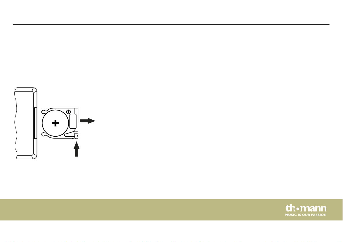
Inserting the battery into the
remote control
Press the lock of the battery holder to the centre of the housing and pull out the battery holder
like a drawer. Insert the battery. The battery is correct if the positive pole points to the housing
base of the remote control. Slide the battery holder back into the remote until it clicks into
place.
When shipping, the battery is already installed in the remote and protected against discharge
by a transparent plastic foil. Remove the plastic foil prior to rst use.
MBA120W MKII HTPT
19
Page 20
Installation
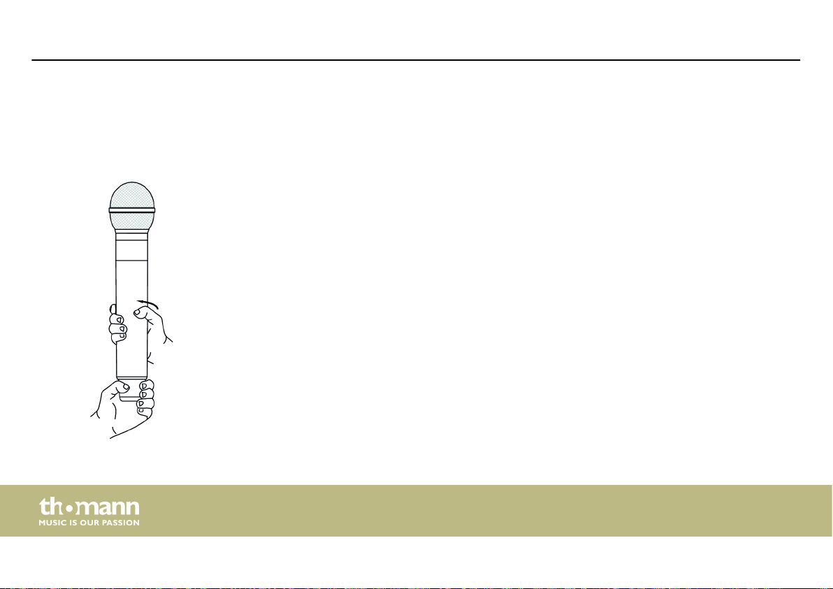
4.3 UHF handheld transmitter
Installation and replacement of
batteries
The battery compartment of the UHF handheld transmitter is located under the grip sleeve
and shares the same thread with the microphone capsule. To access the battery compartment
without accidentally unscrewing the microphone capsule, hold the UHF handheld transmitter
at the bottom of the antenna base and turn the sleeve as shown. After replacing the battery,
close the compartment again. Take care not to over tighten the grip sleeve.
Use only AA batteries or rechargeable Ni-MH batteries (nickel metal hydride). Note the correct
polarity when inserting the batteries.
20
battery-powered speaker
Page 21
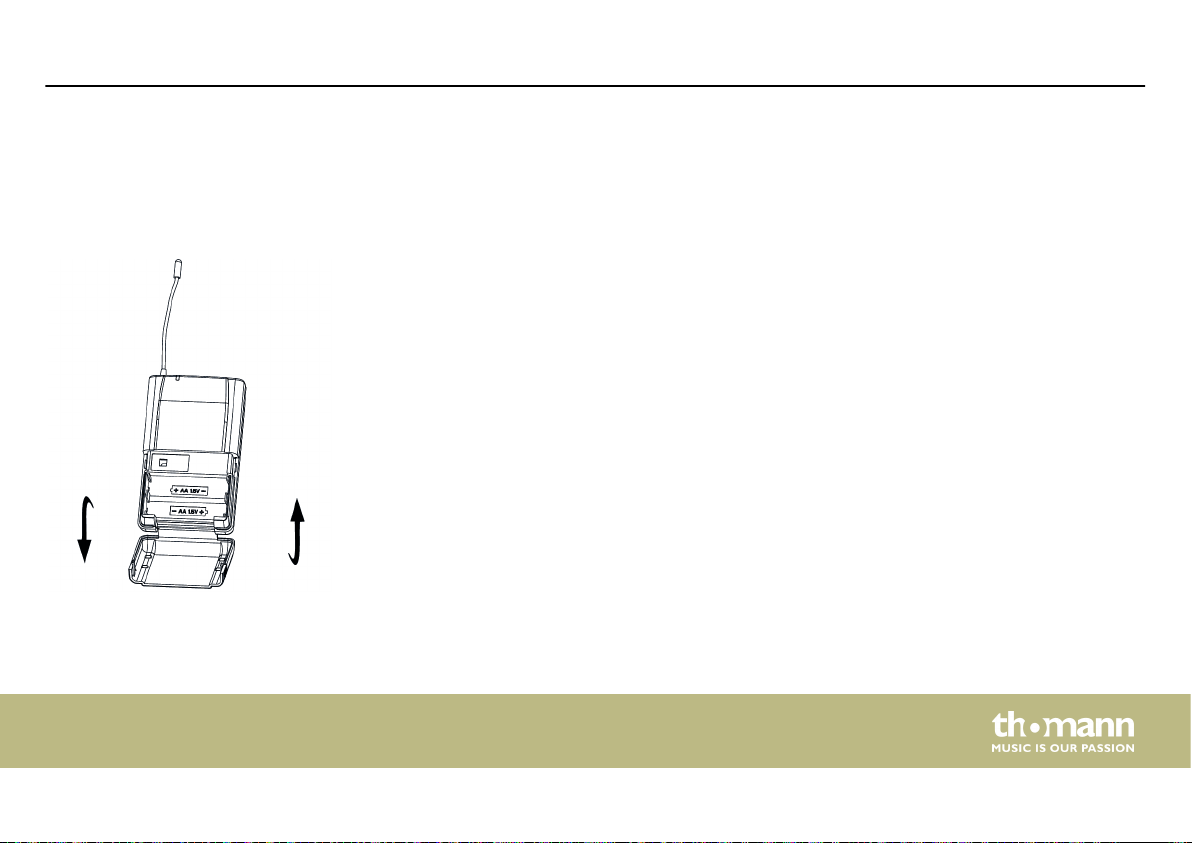
4.4 UHF pocket transmitter
Installation and replacement of
batteries
The battery compartment of the UHF pocket transmitter is located on the back of the device.
Make sure that the main switch is in the [OFF] position. Press the side latches to open the bat‐
tery compartment cover. Insert the batteries. Pay attention to the correct location of the poles.
Close the battery compartment and slide the main switch to the [ON] position. The LED of the
battery status display lights up briey.
Use only AA batteries.
Installation
MBA120W MKII HTPT
21
Page 22

Connections and operating elements
5 Connections and operating elements
Rear view - overview
22
battery-powered speaker
Page 23

Connections and operating elements
Left gure: Device with 1 UHF receiver (item no. 466279, 490317)
Right gure: Device with 2 UHF receivers (item no. 490318, 490319, 490320)
MBA120W MKII HTPT
23
Page 24

Connections and operating elements
5.1 UHF receiver
Partial view A
24
battery-powered speaker
Page 25

Connections and operating elements
1 Channel display.
Double-digit display for selecting and displaying the radio transmission channel (range ‘01’ … ‘16’).
2 [RF | AF]
The red indicator LED [RF] lights up when a radio signal is transmitted between UHF handheld transmitter and UHF
receiver.
The green indicator LED [AF] lights up when an audio signal from an external device is present.
3 [ASC]
Press this button to transfer the channel setting from the device via the infrared port to the microphone.
4 [IR]
Infrared transmitter for transmitting the channel setting from the device to the UHF handheld transmitter.
5 Item no. 466279 and 490317: Additional compartment for a second UHF receiver and second antenna jack.
For mounting a second UHF receiver loosen the two screws and remove the cover plate. The cables for power supply
and signal transmission are already prepared and equipped with suitable plugs. Carefully loosen the cables out of the
device housing and plug them to the corresponding connectors of the UHF receiver. Place the second UHF receiver
in the compartment and fasten it with the two mounting screws. Keep the cover in a safe place.
Item no. 490318, 490319 and 490320: Second UHF receiver and second antenna connection socket.
MBA120W MKII HTPT
25
Page 26

Connections and operating elements
6 [DOWN | UP]
Pushbutton for selecting the radio transmission channel.
Proceed as follows to nd a free channel:
n Turn o the UHF handheld transmitter with the slide switch [ON/OFF] and the UHF receiver with the controller
[POWER-VOL].
n Use [DOWN | UP] to switch through the available channels. If the displayed channel is already in use, the red LED
[RF]. When a free channel is found, press the [ASC] button to transmit the settings to the transmitter.
The rst and (if applicable) second UHF receiver must be tuned to dierent channels.
7 Antenna connector.
8 [MUTE LEVEL]
Control to set the minimum signal strength on the radio transmission channel.
9 [POWER-VOL]
On / o switch and volume control of the UHF receiver.
26
battery-powered speaker
Page 27

5.2 Speaker
5.2.1 Partial view B
Connections and operating elements
MBA120W MKII HTPT
27
Page 28

Connections and operating elements
1 SD card slot
2 Display
3 USB port
4 Selection and control buttons:
[MODE]
Selection button. Press this button to select an audio source: SD card, USB input or Bluetooth port. The active source
is shown on the display.
For setting up and using the Bluetooth interface note Ä Chapter 5.2.5 ‘Playback via Bluetooth’ on page 38.
Depending on operating mode, Play / Pause button to start / stop playback or button to select a menu item.
Stop button to stop playback
28
battery-powered speaker
Page 29

Connections and operating elements
Selection button. Press the button repeatedly to activate a playback mode. The active mode and the title of the cur‐
rent track will appear on the display:
n Normal ‘N’ . All tracks of the selected audio source are played in succession according to the MP3 le date. The
prerequisite for this is that a subdirectory with the desired titles has been created on the data medium.
n Random ‘R’
n Intro ‘I’ . The rst ten seconds of each track of the selected audio source will be played.
n All ‘A’
n Single ‘1’ . Only the selected track is repeated in a loop.
n Folder ‘F’
Depending on operating mode, Skip forward (to the next track) or switch to the next menu option.
Keep this button pressed to increase the volume of the internal media player.
Depending on operating mode, Skip backwards (to the previous track) or switch to the previous menu option.
Keep this button pressed to decrease the volume of the internal media player. We highly recommend to keep this
volume at maximum value and adjust the volume with the controller [LEVEL] (24).
. All tracks of the selected audio source are played in random order.
. All tracks in endless loop, like Normal mode.
. All tracks of a specic folder of the selected audio source are being played.
MBA120W MKII HTPT
29
Page 30

Connections and operating elements
5 [LEVEL]
Gain control for channel 3. Use this control to adjust the level of the input signal in Channel 3.
6 [ON | LIMIT]
Indicator LED (green). This LED lights solid in normal operation and ickers when the box is overdriven. In this case,
turn the gain control of the active channel down to reduce the level of the input signal.
7 [MASTER]
Volume control. Use this control to adjust the overall volume of the device (sum of all input channels).
8 [EFFECT]
Eects control. Use this control to adjust the amount of built-in Delay eect on the overall volume for all channels.
9 [EQ LOW | HIGH]
Equalizer. Controller for adjusting the high and low frequencies in a range of [–15] … [+15].
10 [CH3]
Signal input for channel 3, designed as XLR / 1/4" jack combo socket, beneath toggle switch for LINE and MIC input
signal level.
30
battery-powered speaker
Page 31

Connections and operating elements
11 [CH2]
Signal input for channel 2, designed as XLR / 1/4" combo socket, beneath switch between LINE and MIC input signal
level.
12 [CH1]
RCA input sockets to connect an external audio device to channel 1.
13 [LINE IN]
3.5 mm input socket to connect an external audio device to channel 1.
14 [LEVEL]
Gain control for channel 2. Use this control to adjust the level of the input signal in Channel 2.
15 [LEVEL]
Gain control for channel 1. Use this control to adjust the level of the input signal in Channel 1.
16 [CHI | MP]
Channel 1 input signal switch: external device via RCA sockets / 3.5 mm jack or built-in media player.
MBA120W MKII HTPT
31
Page 32

Connections and operating elements
5.2.2 Partial view C
32
battery-powered speaker
Page 33

Connections and operating elements
1 [BATTERY LEVEL]
Charging indicator.
If only the red LED [LOW] lights, the remaining battery capacity is low (<20 %). Then connect the device to the mains
power to charge the batteries.
During charging, the red LED [LOW] lights and the green LEDs [1] … [3] light up one by one depending on charging
level ([1] = 40 %, [2] = 60 %, [3] = 100 %).
When the batteries are completely charged, the red LED [LOW] turns o and the three green LEDs light. When
capacity decreases, the green LEDs turn o one by one.
Please refer also to the instructions in section Ä Chapter 4.1 ‘Speaker’ on page 17.
2 [LINE OUT]
Line output (1/4" socket) to connect an amplier, a PA or an additional speaker.
3 [POWER]
On / o switch and fuse holder.
MBA120W MKII HTPT
33
Page 34

Connections and operating elements
4 [CHARGE]
This LED lights green during charging. Once the installed battery pack is fully charged, the LED turns o.
5 IEC chassis plug for power connection and mains voltage selector switch.
Once the unit is connected to the mains, the built-in rechargeable batteries are being charged even when the power
is o.
34
battery-powered speaker
Page 35

5.2.3 Partial view D
Connections and operating elements
MBA120W MKII HTPT
35
Page 36

Connections and operating elements
1 Mounting screws of the xing plate
2, 3 VRLA batteries 1 and 2
Observe the correct polarity when wiring the batteries. Connect the red cable to the positive pole of battery 1 and
the black cable to the negative pole of battery 2. Use the blue cable to connect the negative pole of battery 1 to the
positive pole of battery 2.
36
battery-powered speaker
Page 37

5.2.4 Display
Connections and operating elements
a Play/Pause.
b Endless loop.
c Number of the currently playing track and number of tracks in the current folder.
d Selected EQ setting.
e Bit rate and le type of the currently playing track.
f Symbol for the selected data source.
g Elapsed time / total time of the currently playing track.
h Frequency spectrum bar graph.
i File name of the currently playing track.
MBA120W MKII HTPT
37
Page 38

Connections and operating elements
5.2.5 Playback via Bluetooth
Establishing connection to Bluetooth device
Follow the instructions given in the manual of the Bluetooth device and turn it on. Place it near
the device.
Press [MODE] and select the Bluetooth interface as the source for playback. After a few seconds
your Bluetooth device is detected. The display shows the message ‘BT Connected’ . If it does
not work automatically, press and start synchronisation from the Bluetooth device.
Bluetooth menu
Hold [MODE] pressed for a few seconds to open the Bluetooth menu.
To navigate within the menu, use [PREV / NEXT]. To select an option, use [PLAY / PAUSE].
The menu oers the following options:
n ‘Recently reconnection’ – re-connect to the last used Bluetooth device.
n ‘EQ’
– ‘Normal’ – Normal
– ‘Pop’ – Pop music
– ‘Rock’ – Rock music
– ‘Jazz’ – Jazz
38
battery-powered speaker
Page 39

Connections and operating elements
– ‘Classic’ – Classic music
– ‘County’ – Country music
– ‘Lowbass’ – Bass boost
n ‘Deleted paired info’ – erases all information on last link with a Bluetooth device. Try this
option to solve problems establishing a Bluetooth connection.
n ‘Device Information’
interface of the device on the display.
n ‘Exit’ – to exit the menu.
– shows information about the name and address of the Bluetooth
MBA120W MKII HTPT
39
Page 40

Connections and operating elements
5.3 Remote control
40
battery-powered speaker
Page 41

Connections and operating elements
1 [CHANNEL]
No function.
2 [VOL– / VOL+]
To decrease or increase the volume.
3 [PREV / NEXT]
Forward (skip to the next track) or backward (skip to the previous track).
4 Numeric keypad for direct access to tracks.
5 [MODE]
Selection button. Press this button to select an audio source: SD card, USB input or Bluetooth port. The active source
is shown on the display.
For setting up and using the Bluetooth interface note .
MBA120W MKII HTPT
41
Page 42

Connections and operating elements
6 [ENTER]
This button opens a menu with the following options:
n ‘EQ’ – selects an equalizer setting, corresponds to the key [EQ] on the remote.
n ‘PLAY MODE’ – selects a play mode, corresponds to the key on the unit.
n ‘CHANGE DEVICE’
n ‘EXIT’ – to exit the selection menu.
To navigate within the selection menu use [PREV / NEXT]. To select an option use [PLAY/PAUSE].
7 [PICK SONG]
No function.
– selects an audio source, corresponds to the key [MODE] on the remote.
42
battery-powered speaker
Page 43

8 [EQ]
Selects an EQ setting:
n ‘NOR’ – Normal
n ‘POP’
n ‘ROCK’ – Rock music
n ‘JAZZ’
n ‘CLAS’ – Classic music
n ‘COU’
n ‘BAS’ – Bass boost
9 [PLAY/PAUSE]
Play / pause button to start / stop playback.
– Pop music
– Jazz
– Country music
Connections and operating elements
MBA120W MKII HTPT
43
Page 44

Connections and operating elements
5.4 UHF handheld transmitter
44
battery-powered speaker
Page 45

Connections and operating elements
1 Microphone head grill to prevent damage and to reduce wind and breath noise.
2 Lower housing part. Unscrew to open.
3 [BATT]
This LED shows the state of the batteries. When the UHF handheld transmitter is turned on and the capacity of the
battery is sucient, the LED lights green. When the batteries are exhausted, the LED lights red.
4 [ON/OFF]
Slide switch to turn the UHF handheld transmitter on and o.
5 Infrared sensor for receiving the channel setting from the device to the UHF handheld transmitter. The sensor is
accessible after removal of the lower housing part. After each change, transfer the channel setting from the device to
the UHF handheld transmitter. Place the UHF handheld transmitter as close as possible to the device and then press
[ASC]. The LED [RF ] LED lights up when the transmission was successful.
6 Battery compartment for 2 AA cells or appropriate rechargeable batteries.
MBA120W MKII HTPT
45
Page 46

Connections and operating elements
7 [GAIN]
Control to adjust the sensitivity of the UHF handheld transmitter.
8 [H/L]
Switch for selecting the transmission level. In ‘L’ position, a low level is used to save the batteries. As a result, the
range is reduced to about 10 m. In ‘H’ position, a high level is used for an expanded transmission range (about 30 m).
This reduces battery life.
46
battery-powered speaker
Page 47

5.5 UHF pocket transmitter
Connections and operating elements
MBA120W MKII HTPT
47
Page 48

Connections and operating elements
UHF pocket transmitter
1, 6 Antenna
2 Battery status indicator
LED lights up red: Battery capacity insucient.
3 3.5 mm jack socket to connect the headset.
4 [MIC] | [0 dB] | [–10 dB]
Gain switch. Toggles the level between [MIC], [0 dB] and [–10 dB].
5 [ON] | [STANDBY] | [OFF]
Main switch
[ON]: The device is turned on.
[OFF]: The device is turned o.
[STANDBY]: The device is in standby mode.
Headset
48
battery-powered speaker
Page 49

7 3.5 mm jack socket for connection to the UHF pocket transmitter
8 Microphone
Connections and operating elements
MBA120W MKII HTPT
49
Page 50

Technical specications
6 Technical specications
6.1 Speaker
Speaker Two-way system with 1" compression driver and 10" woofer
Input connections Microphone/Line 2 × XLR/1/4" combo socket
Line (stereo) 1 × 3.5 mm jack socket
2 × RCA sockets for additional signal input, for CD
players or similar devices with line out signal
USB port USB A
Power supply IEC chassis plug C14
Output connector Line out 1 × 1/4" phone socket
Output power Mains operation 120 W (RMS)
360 W (Peak)
50
Battery operation 80 W
battery-powered speaker
Page 51

Frequency range 55 Hz … 18 kHz, –3 dB
Power consumption 43 W
Bluetooth® Frequency of operation 2.402 GHz … 2.480 GHz
Max. transmission power +4 dBm
Technical specications
Supply voltage
Fuse 110 V: 5 mm × 20 mm, 2 A, 250 V, slow-blow
Operating time per battery charge Music: approx. 4 h
Charging time 10 h … 12 h
110 V , 60 Hz / 230 V , 50 Hz
2 × 12 V lead-gel rechargeable batteries (VRLA batteries, 5 Ah each), maintenance-free
Recommended types:
n Ritar RT1250
n Fiamm FG20451
230 V: 5 mm × 20 mm, 1 A, 250 V, slow-blow
Speech: approx. 6 h
MBA120W MKII HTPT
51
Page 52

Technical specications
Battery remote control Battery type Lithium button cell, 3 V, CR 2025
or rechargeable Ni-MH batteries (nickel metal
hydride)
Dimensions (W × H × D) 360 mm × 290 mm × 567 mm
Weight 19 kg
Ambient conditions Temperature range 0 °C…40 °C
Relative humidity 20 %…80 % (non condensing)
52
battery-powered speaker
Page 53

Further information
Incl. player Yes
Incl. microphone Yes
Incl. radio system Yes
Incl. subwoofer No
Incl. cover No (optional, item no. 382254)
6.2 UHF receiver
Carrier frequency UHF band (863 MHz … 865 MHz)
NF frequency response 60 Hz … 16 kHz, –3 dB
Modulation type Frequency modulation (FM)
Technical specications
MBA120W MKII HTPT
53
Page 54

Technical specications
Signal-to-noise ratio > 100 dB
THD < 0.1 %
6.3 UHF handheld transmitter
Frequency of operation 863 MHz … 865 MHz
Max. transmission power 10 mW
Maximum input level –10 dBV
Input impedance (antenna) 50 Ω
Range (free eld) Up to 30 m
Battery Battery type 2 × AA
or rechargeable Ni-MH batteries (nickel metal hydride)
54
battery-powered speaker
Page 55

Voltage 1.5 V
Dimensions (W × H, without antenna) 54 mm × 250 mm
Dimensions antenna (W × H) 13 mm × 250 mm
Weight 270 g
Ambient conditions Temperature range 0 °C…40 °C
Relative humidity 20 %…80 % (non condensing)
6.4 UHF pocket transmitter
Input connections Headset 1 × 3.5 mm jack socket
Number of channels 16
Frequency of operation 863 MHz … 865 MHz
Technical specications
MBA120W MKII HTPT
55
Page 56

Technical specications
Max. transmission power 10 mW
Frequency response 50 Hz … 16 kHz
Maximum depth of modulation +55 kHz
Maximum output 250 mV
Wave impedance 50 dBc
Battery / rechargeable battery Battery type 2 × AA
or rechargeable Ni-MH batteries (nickel metal hydride)
Voltage 1.5 V
Capacity 1000 mAh
Dimensions (W × H × D, without
antenna)
Weight 80 g
56
105 mm × 65 mm × 24 mm
battery-powered speaker
Page 57

Technical specications
Ambient conditions Temperature range 0 °C…40 °C
Relative humidity 20 %…80 % (non condensing)
6.5 Headset
Output connections Audio signal 3.5 mm jack socket for connection to the UHF
pocket transmitter
Output impedance ≤680 Ω
Sensitivity –47 dB (+2 dB)
Signal-to-noise ratio 58 dB
NF frequency response 20 Hz … 20 kHz (–2 dB)
Power consumption 0.5 mA
MBA120W MKII HTPT
57
Page 58

Technical specications
Voltage supply via connected UHF pocket trans‐
mitter
Ambient conditions Temperature range 0 °C…40 °C
Relative humidity 20 %…80 % (non condensing)
1.5 V
battery-powered speaker
58
Page 59

7 Plug and connection assignment
Plug and connection assignment
Introduction
Balanced and unbalanced trans‐
mission
This chapter will help you select the right cables and plugs to connect your valuable equip‐
ment in such a way that a perfect sound experience is ensured.
Please note these advices, because especially in ‘Sound & Light’ caution is indicated: Even if a
plug ts into the socket, an incorrect connection may result in a destroyed power amp, a short
circuit or ‘just’ in poor transmission quality!
Unbalanced transmission is mainly used in semi-professional environment and in hi use.
Instrument cables with two conductors (one core plus shielding) are typical representatives of
the unbalanced transmission. One conductor is ground and shielding while the signal is trans‐
mitted through the core.
Unbalanced transmission is susceptible to electromagnetic interference, especially at low
levels, such as microphone signals and when using long cables.
In a professional environment, therefore, the balanced transmission is preferred, because this
enables an undisturbed transmission of signals over long distances. In addition to the conduc‐
tors ‘Ground’ and ‘Signal’, in a balanced transmission a second core is added. This also transfers
the signal, but phase-shifted by 180°.
MBA120W MKII HTPT
59
Page 60

Plug and connection assignment
1/4" TS phone plug (mono,
unbalanced)
1/4" TRS phone plug (mono, bal‐
anced)
Since the interference aects both cores equally, by subtracting the phase-shifted signals, the
interfering signal is completely neutralized. The result is a pure signal without any noise inter‐
ference.
1 Signal
2 Ground, shielding
1 Signal (in phase, +)
2 Signal (out of phase, –)
3 Ground
60
battery-powered speaker
Page 61

Three-pole 1/8" mini phone jack
(stereo, unbalanced)
XLR plug (balanced)
Plug and connection assignment
1 Signal (left)
2 Signal (right)
3 Ground, shielding
1 Ground, shielding
2 Signal (in phase, +)
3 Signal (out of phase, –)
4 Shielding on plug housing (option)
MBA120W MKII HTPT
61
Page 62

Plug and connection assignment
RCA connection
Drawing and table indicate the pin assignment of an RCA plug.
1 Signal
2 Ground, shielding
battery-powered speaker
62
Page 63

8 Cleaning
Cleaning
Device components
Clean the device components that are accessible from the outside regularly. The cleaning fre‐
quency depends on the operating environment: damp, smoky or particularly dirty environ‐
ments can cause greater accumulation of dirt on the device components.
n Clean with a dry soft cloth.
n Stubborn dirt can be removed with a slightly dampened cloth.
n Never use solvents or alcohol for cleaning.
MBA120W MKII HTPT
63
Page 64

Protecting the environment
9 Protecting the environment
Disposal of the packaging mate‐
rial
For the transport and protective packaging, environmentally friendly materials have been
chosen that can be supplied to normal recycling.
Ensure that plastic bags, packaging, etc. are properly disposed of.
Do not just dispose these materials with your normal household waste, but make sure that
they are fed to a recovery. Please follow the notes and markings on the packaging.
Disposal of batteries
Batteries must not be disposed of as domestic waste or thrown into re. Dispose of the bat‐
teries according to national or local regulations regarding hazardous waste. To protect the
environment, dispose of empty batteries at your retail store or at appropriate collection sites.
64
battery-powered speaker
Page 65

Disposal of your old device
Protecting the environment
This product is subject to the European Waste Electrical and Electronic Equipment Directive
(WEEE) in its currently valid version. Do not dispose with your normal household waste.
Dispose this device through an approved waste disposal rm or through your local waste
facility. When discarding the device, comply with the rules and regulations that apply in your
country. If in doubt, consult your local waste disposal facility.
MBA120W MKII HTPT
65
Page 66

Notes
66
battery-powered speaker
Page 67

Page 68

Musikhaus Thomann · Hans-Thomann-Straße 1 · 96138 Burgebrach · Germany · www.thomann.de
 Loading...