

Page 1
DSP 4x4 Mini Amp
digital speaker
management system
user manual
Page 2

Musikhaus Thomann
Thomann GmbH
Hans-Thomann-Straße 1
96138 Burgebrach
Germany
Telephone: +49 (0) 9546 9223-0
E-mail: info@thomann.de
Internet: www.thomann.de
15.01.2021, ID: 495806
Page 3

Table of contents
Table of contents
1 General information................................................................................................................................. 4
1.1 Further information........................................................................................................................... 5
1.2 Notational conventions.................................................................................................................... 6
1.3 Symbols and signal words............................................................................................................... 7
2 Safety instructions..................................................................................................................................... 9
3 Features....................................................................................................................................................... 13
4 Installation and starting up................................................................................................................ 14
5 Connections and controls................................................................................................................... 16
6 Operating on the computer............................................................................................................... 18
7 Technical specications....................................................................................................................... 35
8 Plug and connection assignment.................................................................................................... 38
9 Protecting the environment.............................................................................................................. 39
DSP 4x4 Mini Amp
3
Page 4

General information
1 General information
This user manual contains important information on the safe operation of the device. Read and
follow all safety notes and all instructions. Save this manual for future reference. Make sure
that it is available to all persons using this device. If you sell the device to another user, be sure
that they also receive this manual.
Our products and user manuals are subject to a process of continuous development. We there‐
fore reserve the right to make changes without notice. Please refer to the latest version of the
user manual which is ready for download under www.thomann.de.
digital speaker management system
4
Page 5
1.1 Further information
General information
On our website (www.thomann.de) you will nd lots of further information and details on the
following points:
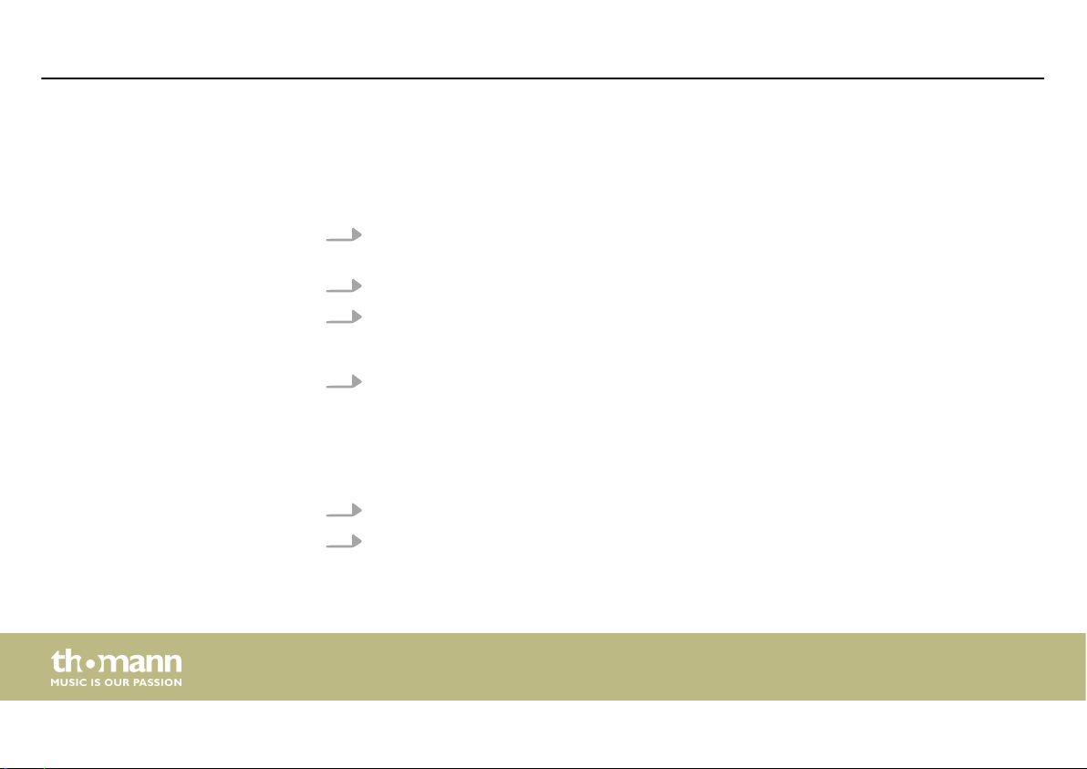
Download This manual is also available as PDF le for you to download.
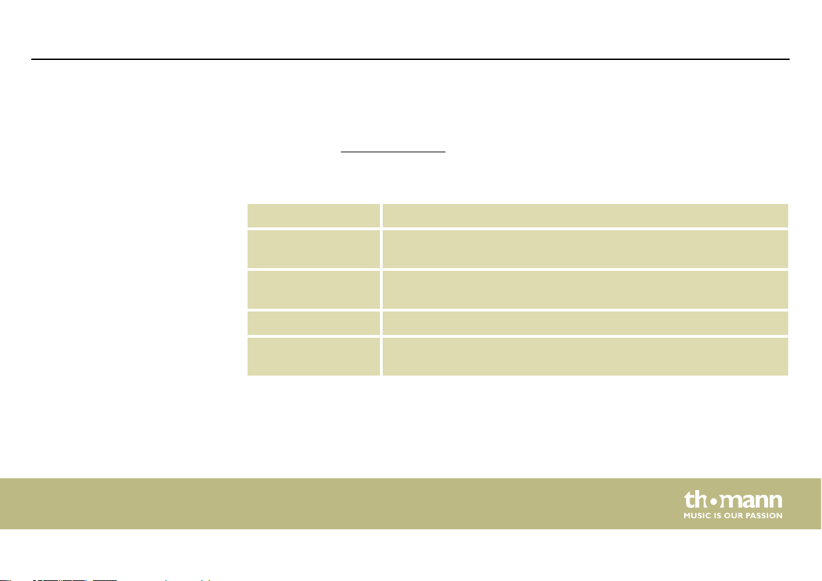
Keyword search
Online guides
Personal consultation For personal consultation please contact our technical hotline.
Service
Use the search function in the electronic version to nd the topics of
interest for you quickly.
Our online guides provide detailed information on technical basics
and terms.
If you have any problems with the device the customer service will
gladly assist you.
DSP 4x4 Mini Amp
5
Page 6

General information
1.2 Notational conventions
This manual uses the following notational conventions:
Letterings
Displays
6
The letterings for connectors and controls are marked by square brackets and italics.
Examples: [VOLUME] control, [Mono] button.
Texts and values displayed on the device are marked by quotation marks and italics.
Examples: ‘24ch’ , ‘OFF’.
digital speaker management system
Page 7
General information
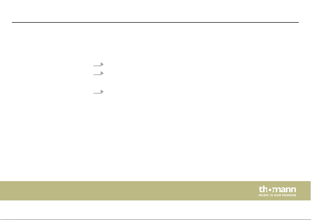
Instructions
The individual steps of an instruction are numbered consecutively. The result of a step is
indented and highlighted by an arrow.
Example:
1. Switch on the device.
2. Press [Auto].
3. Switch o the device.
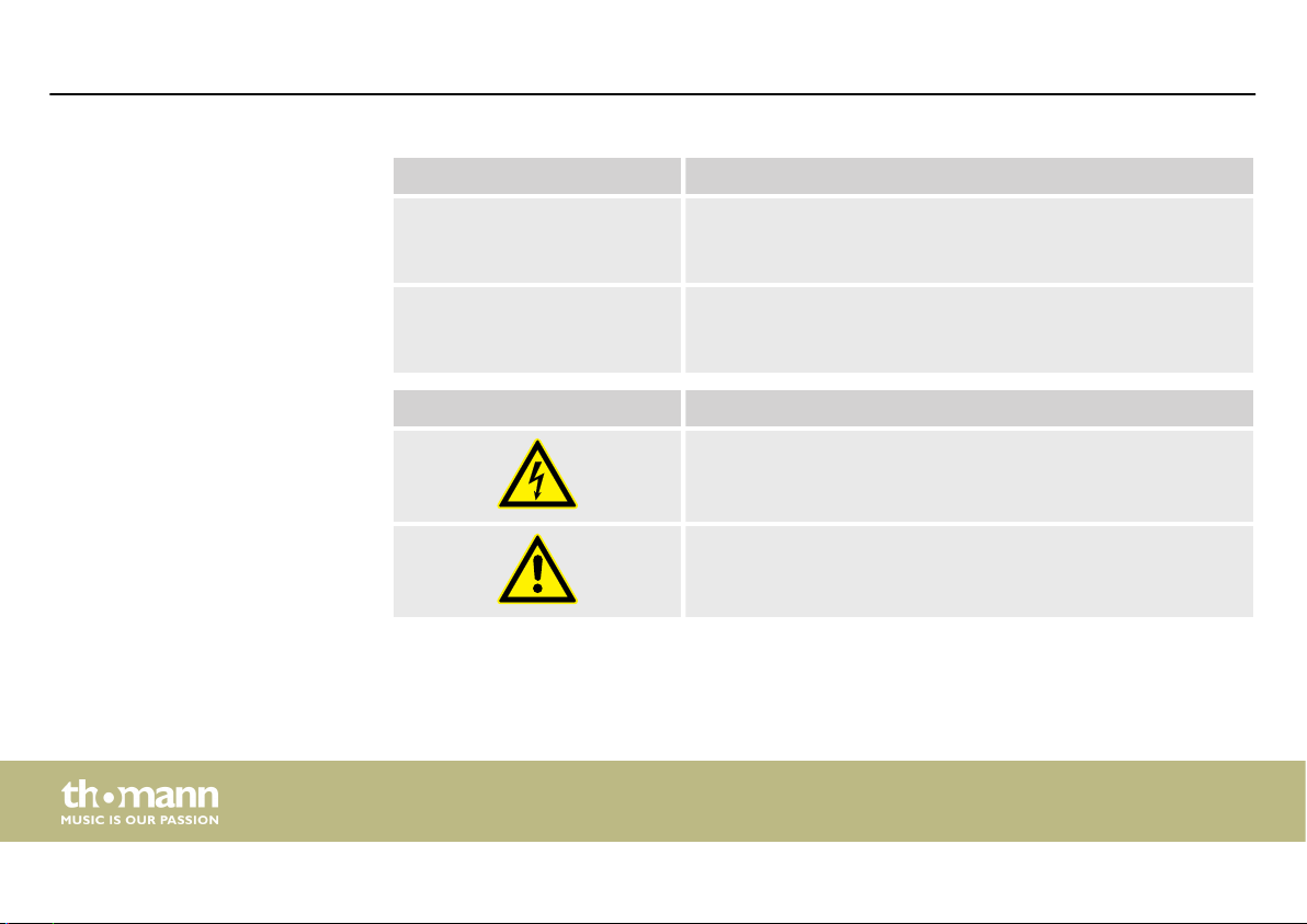
1.3 Symbols and signal words
In this section you will nd an overview of the meaning of symbols and signal words that are
used in this manual.
Automatic operation is started.
ð
DSP 4x4 Mini Amp
7
Page 8
General information
Signal word Meaning
DANGER! This combination of symbol and signal word indicates an
immediate dangerous situation that will result in death or
serious injury if it is not avoided.
NOTICE! This combination of symbol and signal word indicates a pos‐
sible dangerous situation that can result in material and
environmental damage if it is not avoided.
Warning signs Type of danger
Warning – high-voltage.
Warning – danger zone.
digital speaker management system
8
Page 9

2 Safety instructions
Safety instructions
Intended use
This device is intended to be used for amplication, mixing and playback of signals from
musical instruments and microphones. Use the device only as described in this user manual.
Any other use or use under other operating conditions is considered to be improper and may
result in personal injury or property damage. No liability will be assumed for damages resulting
from improper use.
This device may be used only by persons with sucient physical, sensorial, and intellectual
abilities and having corresponding knowledge and experience. Other persons may use this
device only if they are supervised or instructed by a person who is responsible for their safety.
DSP 4x4 Mini Amp
9
Page 10
Safety instructions
Safety
DANGER!
Danger for children
Ensure that plastic bags, packaging, etc. are disposed of properly and are not
within reach of babies and young children. Choking hazard!
Ensure that children do not detach any small parts (e.g. knobs or the like) from
the unit. They could swallow the pieces and choke!
Never let children unattended use electrical devices.
DANGER!
Electric shock caused by high voltages inside
Within the device there are areas where high voltages may be present. Never
remove any covers.
There are no user-serviceable parts inside.
Do not use the device if covers, protectors or optical components are missing or
damaged.
10
digital speaker management system
Page 11
Safety instructions
NOTICE!
Risk of re
Do not block areas of ventilation. Do not install the device near any direct heat
source. Keep the device away from naked ames.
DSP 4x4 Mini Amp
11
Page 12
Safety instructions
NOTICE!
Operating conditions
This device has been designed for indoor use only. To prevent damage, never
expose the device to any liquid or moisture. Avoid direct sunlight, heavy dirt, and
strong vibrations.
Only operate the device within the ambient conditions specied in the chapter
‘Technical specications’ of this user manual. Avoid heavy temperature uctua‐
tions and do not switch the device on immediately after it was exposed to tem‐
perature uctuations (for example after transport at low outside temperatures).
Dust and dirt inside can damage the unit. When operated in harmful ambient
conditions (dust, smoke, nicotine, fog, etc.), the unit should be maintained by
qualied service personnel at regular intervals to prevent overheating and other
malfunction.
12
digital speaker management system
Page 13

3 Features
Features
n Ultra-compact 4-channel DSP and 4-channel power amplier
n Ideal for small installations and in combination with ceiling speakers
n Inputs: 4 × 1/4" jack socket (balanced)
n Outputs: 4 ×1/4" jack socket (balanced) and screw terminals
n USB connection for control via PC using the supplied software (cable included)
n Comprehensive setting options for optimal sound
– Parametric Equalizer
– Graphic Equalizer
– High- and low-pass lters
– Noise Gate
– Limiter
– Phase inversion
DSP 4x4 Mini Amp
13
Page 14

Installation and starting up
4 Installation and starting up
Unpack and check carefully there is no transportation damage before using the unit. Keep the
equipment packaging. To fully protect the product against vibration, dust and moisture during
transportation or storage use the original packaging or your own packaging material suitable
for transport or storage, respectively.
Create all connections while the device is o. Use the shortest possible high-quality cables for
all connections. Take care when running the cables to prevent tripping hazards.
14
digital speaker management system
Page 15

Installation and starting up
The gure schematically shows how the device can be controlled via a computer's USB port.Conguration example
DSP 4x4 Mini Amp
15
Page 16

Connections and controls
5 Connections and controls
16
digital speaker management system
Page 17

Front panel
1 LEDs [1], [2], [3], [4]
The LED lights up when a signal is present at the respective input.
2 Inputs [CH 1] … [CH 4], designed as 1/4" phone jack (mono, balanced).
3 [USB]
USB port
4 [POWER]
This LED lights when the device is turned on.
Rear panel
5 [SPEAKER OUTPUT]
Screw terminal strip
6 [PASSIVE OUTPUT]
Outputs [CH 1] … [CH 4], designed as 1/4" phone jack (mono, balanced).
7 Power cord
Connections and controls
DSP 4x4 Mini Amp
17
Page 18
Operating on the computer
6 Operating on the computer
Install and start the software.
1. Insert the software CD into the disk drive of your Windows PC and start the installation
programme that matches the device version.
2. Follow the instructions of the installation programme to completion.
3. Connect your PC to the device via a USB cable and turn on the device.
The operating system detects the newly added USB device.
ð
4. Open the PC programme. It automatically detects the connected device.
In the upper right corner of the programme window the marking ‘Online’ appears.
ð
Exit software
1. Click on the ‘Online’ button in the programme window.
2. Close the programme window.
18
digital speaker management system
Page 19

Operating on the computer
Components of the programme
window
All tabs of the programme window have a similar structure and are divided into the following
areas:
DSP 4x4 Mini Amp
19
Page 20

Operating on the computer
1 Tab for selecting a function group
2 Main menu
3 Button for the status of the connection to the PC
4 Display area
5 Control area
6 Buttons for quick access to important presets
20
digital speaker management system
Page 21

Operating on the computer
Main menu
Menu item Meaning
‘File’ Loading user presets and saving them on the PC
‘Link’ Assignment of input to output channels
‘Copy’ Copying parameter settings from one input or output channel to another
‘Lock’ Changing device password
‘Test Tone’ Setting the internal test tone generator: Pink noise, white noise, sine wave 20 Hz…20 kHz
‘Language’ Language selection for the user interface of the programme (English or German)
‘About’ Information about the programme version
DSP 4x4 Mini Amp
21
Page 22

Operating on the computer
Buttons for quick access to
important presets
Range Meaning
‘Address’ Display of the marking of the device
‘Preset’ Display of the current user's preset
‘Store’ Saving user preset
‘Recall’ Recalling user preset
22
digital speaker management system
Page 23

‘Gain’ tab
Operating on the computer
DSP 4x4 Mini Amp
23
Page 24

Operating on the computer
Range Meaning
Display area The waveform of input and output channels is graphically displayed. Use the radio buttons ‘Inx’ and
‘Outx’ to determine the inputs and outputs to be displayed.
Control area Drag the faders with the mouse to adjust the levels for the input and output channels. The ‘Mute’
button mutes or unmutes the respective channel. The ‘Normal’ /‘Inverse’ button inverts the phase of the
respective channel by 180° when needed.
24
digital speaker management system
Page 25

‘Gate’ tab
Operating on the computer
DSP 4x4 Mini Amp
25
Page 26

Operating on the computer
Range Meaning
Display area Shows the current settings of the noise gate for the respective channel, with a symbolic level indicator
symbol appearing next to it for the input channels. The red dot represents the threshold level at which
the noise gate opens.
Control area Drag the faders with the mouse to set the noise gate parameters for all input and output channels:
Threshold, hold, attack, release
26
digital speaker management system
Page 27

‘Comp’ tab
Operating on the computer
DSP 4x4 Mini Amp
27
Page 28

Operating on the computer
Range Meaning
Display area Shows the current settings of the compressor function for the respective output channel, with a sym‐
bolic level indicator symbol appearing next to it for all output channels. The red dot marks the threshold
from which the compressor operates.
Control area Drag the faders with the mouse to set the compressor parameters for the output channels: Threshold,
ratio, knee, attack, release
28
digital speaker management system
Page 29

‘Delay’ tab
Operating on the computer
DSP 4x4 Mini Amp
29
Page 30

Operating on the computer
Range Meaning
Display area Shows the set delays for all output channels.
Control area Drag the faders with the mouse to adjust the delay for the respective channel. In the Unit area, you can
select the measuring unit milliseconds (ms), meters (m) or feet (ft).
30
digital speaker management system
Page 31

‘Matrix’ tab
Operating on the computer
DSP 4x4 Mini Amp
31
Page 32

Operating on the computer
Range Meaning
Display area Shows the current interconnection of input to output channels.
Input and output channels can be renamed. Click on a function area (such as ‘PEQ’ or ‘DELAY’) to open
the tab. Here you can enter the corresponding parameters directly.
Control area With a mouse click you can interconnect each input with each output channel. To each output channel,
an input channel or the mix of several input channels can be freely assigned. The green input channels
are assigned to the respective output channel. You can adjust the level for each combination of input
and output channel.
32
digital speaker management system
Page 33

‘Out 1’ – ‘Out 4’
Operating on the computer
DSP 4x4 Mini Amp
33
Page 34

Operating on the computer
Range Meaning
Display area Use the radio buttons ‘Mag’ or ‘Phase’ to switch the diagram from Cartesian coordinates (level vs. fre‐
quency) to polar coordinates (angle vs. frequency).
Use the radio button ‘SHOW ALL EQ’ to show the parameters for all seven of the frequency bands.
The corner points of the equalizer can be moved in the display area with the mouse.
Control area You can enter the parameters of the parametric equalizer for each input channel and all seven fre‐
quency bands (numbered with ‘PEQ’ ) in the left part of the window directly as numerical values: Centre
frequency, lter quality, slope, lter type. With the ‘Bypass’ button, the equalizer for the respective fre‐
quency band and the respective channel can be turned o temporarily.
In the middle part of the window ( ‘PEQ Parameter’ ) you can set the parameters centre frequency, lter
quality, and slope using the faders. The setting refers to the frequency band that is highlighted green in
the left part of the window.
You can select the cut-o frequency and the lter type for the low pass and the high pass lter. Use the
‘Bypass’ button to temporarily turn o the lter.
Drag the fader in the right part of the window using the mouse to set the level for the input channel.
The ‘Mute’ button mutes or unmutes the respective channel. The ‘Normal’/‘Inverse’ button inverts the
phase of the respective channel by 180° when needed.
34
digital speaker management system
Page 35

Technical specications
7 Technical specications
Amp class D
Input connections Audio signal Type 4 × 1/4" jack socket, balanced
Level +12 dBu
Impedance 1 MΩ (stereo), 500 kΩ (mono)
Output connections Audio signal Type 4 × 1/4" jack socket, balanced
Level +12 dBu
Impedance < 500 Ω
Frequency response 20 Hz … 20 kHz
–0.3 dB
Total harmonic distortion (THD) < 0.5 % (1 kHz, 0 dBu)
Signal-to-noise ratio > 95 dBu
DSP 4x4 Mini Amp
35
Page 36

Technical specications
Crosstalk > 70 dBu
20 Hz … 20 kHz
Digital signal processing Digital signal processor 32 bit
A/D-D/A converter 24 bit
Sampling rate 48 kHz
Output power 8 Ω 4 × 50 W RMS
4 Ω 4 × 60 W RMS
Operating supply voltage
Dimensions (W × H × D) 240 mm × 160 mm × 43 mm
Weight 1.6 kg
Ambient conditions Temperature range 0 °C…40 °C
AC 230 V 50 Hz
Relative humidity 50 %, non-condensing
digital speaker management system
36
Page 37

Further information
2-way stereo Yes
3-way stereo No
Digital Yes
Delay Yes
EQ Yes
Limiter Yes
Computer remote Yes
RTA connection No
Suitable for rack mounting No
Bridged operation No
Temperature-controlled fan No
Convection cooling Yes
Technical specications
DSP 4x4 Mini Amp
37
Page 38

Plug and connection assignment
8 Plug and connection assignment
Introduction
1/4" TRS phone plug (mono, bal‐
anced)
38
This chapter will help you select the right cables and plugs to connect your valuable equip‐
ment in such a way that a perfect sound experience is ensured.
Please note these advices, because especially in ‘Sound & Light’ caution is indicated: Even if a
plug ts into the socket, an incorrect connection may result in a destroyed power amp, a short
circuit or ‘just’ in poor transmission quality!
1 Signal (in phase, +)
2 Signal (out of phase, –)
3 Ground
digital speaker management system
Page 39

9 Protecting the environment
Disposal of the packaging mate‐
rial
For the transport and protective packaging, environmentally friendly materials have been
chosen that can be supplied to normal recycling.
Ensure that plastic bags, packaging, etc. are properly disposed of.
Do not just dispose of these materials with your normal household waste, but make sure that
they are collected for recycling. Please follow the notes and markings on the packaging.
Disposal of your old device
This product is subject to the European Waste Electrical and Electronic Equipment Directive
(WEEE) in its currently valid version. Do not dispose with your normal household waste.
Dispose of this device through an approved waste disposal rm or through your local waste
facility. When discarding the device, comply with the rules and regulations that apply in your
country. If in doubt, consult your local waste disposal facility.
Protecting the environment
DSP 4x4 Mini Amp
39
Page 40

Notes
40
digital speaker management system
Page 41

Notes
DSP 4x4 Mini Amp
41
Page 42

Notes
42
digital speaker management system
Page 43

Page 44

Musikhaus Thomann · Hans-Thomann-Straße 1 · 96138 Burgebrach · Germany · www.thomann.de
 Loading...