

Thoebe Servo-Loop Preamplifier Owner's Manual
Your Thoebe Servo-Loop Preamplifier derives
performance from the technology and experience Great American
Sound Company engineers have gained from the development of
Thaedra. To insure equal performance, Thoebe uses
circuitry (i.e. phono and line amp cards).
is
The result
equipment.
It must be remembered that Thoebe is a complex, highly sophisticated
example of electronic equipment and some common sense must be
exercised when operating it.
a welcome addition to our growing line of Audiophile
its
"State of the Art"
identical
active
INTRODUCTION
1.
When Thoebe
seconds before anything will be heard. DO NOT attempt to turn up
gain during this period. When the relay closes, you may be delivering
in excess of
probably will not save your speakers (or ears) from permanent
damage.
2.
Turn level down between musical or source selections and when
turning the power on or off.
3.
Thoebe runs warm! Make sure it has adequate ventilation.
WARNING:
appliance to rain or moisture.
is
turned on, there will be a time delay of several
10V
RMS signal to amplifier, your reaction time
To prevent fire or shock hazard, do not expose this
UNPACKING
Immediately upon receiving Thoebe, inspect the carton for evidence of
mishandling during shipment. Then, carefully unpack the amplifier
and inspect it for any sign of damage. Please save the shipping carton
and all the associated packing materials for future use. The shipping
materials have been carefully designed to transport your Thoebe with a
minimum of disturbance.
must
Shipment to the factory for any purpose
carton and packing. If the original carton
G.A.S. Company for replacement.
NOTE: If damage has occurred in shipping, please contact your dealer
immediately.
THOEBE is designed primarily for mounting on a shelf. An optional
is
wood cabinet
available.
be made in the original
is
lost or damaged, contact
Where THOEBE
cutout must be provided.
Allow enough space and/or holes for proper ventilation
cjrcumstances should the ventilation slots on the top and bottom of the
chassis be blocked.
RACK-MOUNTING: A rack mount panel version of THOEBE
available from your dealer, for use with the standard,
rack. Be certain that the insulating plastic bushings (provided with the
panel) are used under each mounting screw to provide electrical
isolation of the unit from the metal rack.
CAUTION: Under no circumstances should you mount the unit in
is
to be inserted into a panel,
vertical position. This will cause overheating of the unit.
a
17
inch by
-
19
5-114
Under no
inch metal
inch
is
a
With the power switch in the OFF position, plug the line cord into any
105-125V. 50 or
other connections have been completed.
60Hz
outlet. Do not turn on the power switch until all
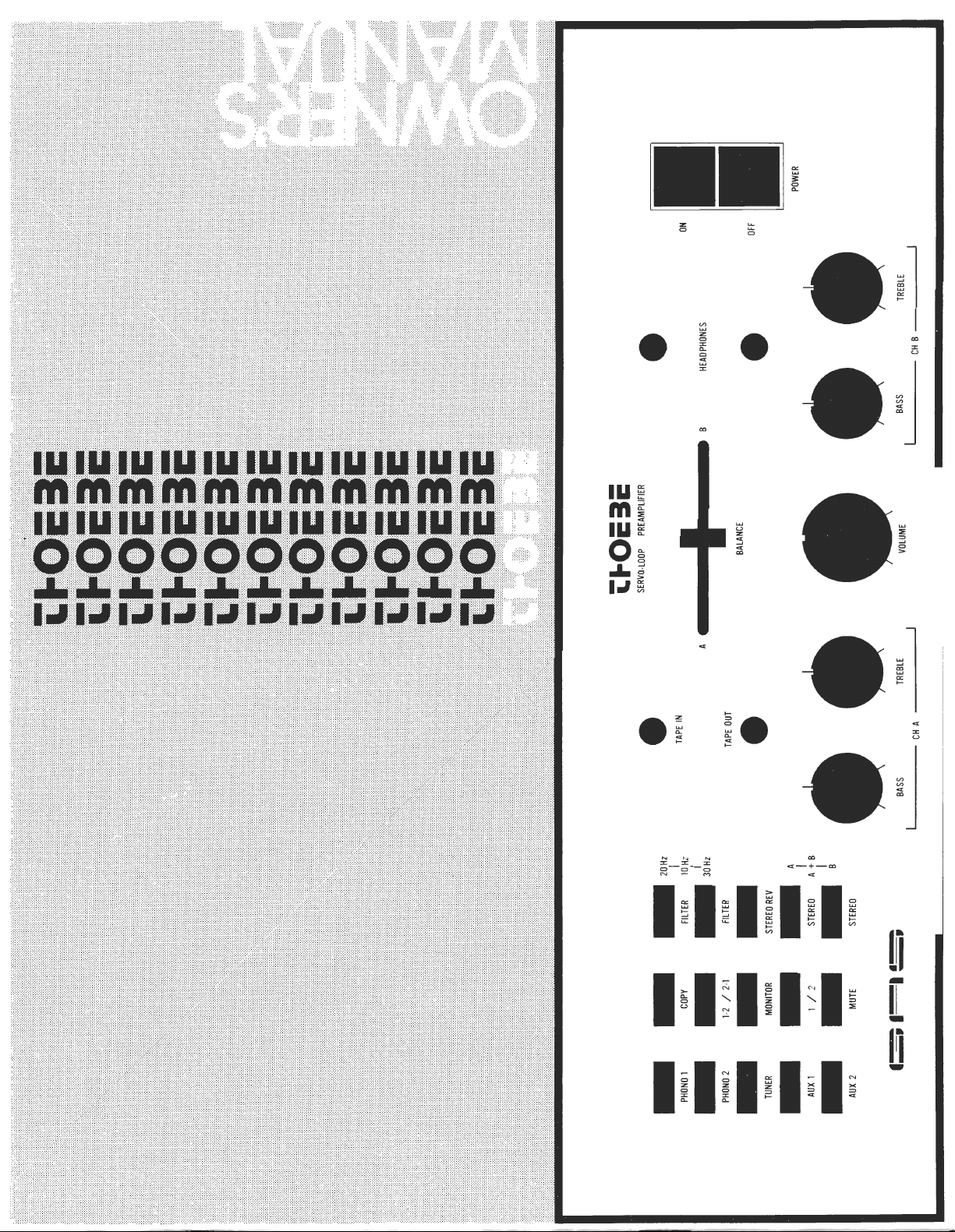
CONVENIENCE OUTLETS:
Refer
to
pictorial
Four convenience outlets have been provided on the rear panel to
power associated components in your system. Of these outlets, three
are controlled by the front panel onloff switch
use with tape recorders, and medium powered amplifiers, (i.e. Son of
Ampzilla). The one remaining outlet
turntables that have built-in power switches mechanically linked to
disengage their rubber idler wheels.
NOTE: We do not recommend using these outlets with high power
amplifiers. AMPZILLA cannot be plugged into these outlets.
Under no circumstances should
be used to plug the AMPZILLA line cord into one of Thoebe's
convenience outlets! To keep within
AMPZILLA must be powered directly from
the third wire can be grounded (No ground wire
recommended for Thoebe).
A
(1000
Watts total) for
is
unswitched and may be used for
a
three-to-two prong adapter
its
warranty provisions,
a
wall outlet where
is
required or
PRE-PREAMP POWER SUPPLY
Located on the back panel of Thoebe
+
connector. This supplies
28V for using Goliath pre-preamp.
JACK
is
a power supply output
MAlN OUTPUTS
CONNE
FSi&
Refer to pictorial
Two stereo sets of audio output jacks are provided for connection to
power amplifiers or electronic crossovers. Special audio cables with
gold-plated contacts have been supplied for this purpose. The
gold-plated contacts have the low resistance necessary for a reliable
interconnection throughout the life of the equipment; additionally, the
high quality coaxial cable with braided shield guarantees highest
possible isolation from external electrostatic and electromagnetic
radiation.
The stereo output jacks are labeled MAlN 1 and
identical and turn on is time-delayed by a relay.
Make certain that the cable contacts are fully engaged so that no loss of
circuit ground exists when the equipment is turned on. A very loud
hum or buzz will be heard if this condition does occur.
The source impedance of the two main outputs are each 60 Ohms, low
enough to permit the use of shielded, interconnecting cables up to 100
feet in length.
A
2.
They are both
TAPE OUTPUTS
Refer to pictorial
Two pairs of stereo output jacks are provided on the rear panel for
connection to any tape recorder having a minimum load impedance of
5K
Ohms or higher. Since the source impedance of each
cables up to 100 feet may be used without high-frequency attenuation.
Unlike the main' outputs, the tape-output signals are independant of
balance, volume and tone control settings and are at a level equal to the
source-input level (Tuner, Aux, Etc.)
NOTE: The TAPE OUT stereo phone jack on the front panel has been
provided for tape-copying purposes and may always be utilized
in the same manner as the rear outputs. (Refer to the
paragraph on TAPE COPYING).
A
&
B
is
500
Ohms,
 Loading...