


© Third Dimension Confidential Document D13-1604-OP-EN-3.3
V7.5

2
© Third Dimension Confidential Document D13-1604-OP-EN-3.3
V7.5
Copyright © 2016 Third Dimension
All rights reserved.
You must not reproduce or distribute any part of this
publication in any form or by any means, electronic or
mechanical, without prior permission in writing from
Third Dimension. This includes photocopying, recording
or any other information storage or retrieval system.
This version produced on 16 September 2016
For support with your GapGun Pro please contact Third
Dimension:
Brabazon Office Park, Bristol, BS34 7PZ, UK
T: +44 (0)3333 44 3000
F: +44 (0)3333 44 0041
E: support@third.com
www.third.com
The laser complies with IEC60825-1 AM2:2001.
Because your blink reflex provides enough protection, it
is called eye safe
• Do not shine in eyes
• Do not view with optical instruments
• Do not shine in open space
• Take care around reflective surfaces
LASER RADIATION
DO NOT STARE INTO BEAM
OR VIEW DIRECTLY WITH
OPTICAL INSTRUMENTS
CLASS 2M LASER PRODUCT

© Third Dimension Confidential Document D13-1604-OP-EN-3.3
V7.5
3
Page
Operator Guide 3
The GapGun Pro 4
Measuring with the GapGun 8
Checking Sensor Calibration 14
Administrator Guide 15
Creating a Checkplan 17
Measuring a Works Order 20
Setting nominals and tolerances 21
Glossary 23

4
© Third Dimension Confidential Document D13-1604-OP-EN-3.3
V7.5
A. Laser source
B. Camera
C. Green indicator LEDs
D. Vchange collar release
E. Trigger
F. On / Off switch
G. USB slot
H. Touch screen display
I. Head power indicator
J. Red laser activity indicator
K. Drop Protection jacket
L. V-Standoff
M. Wrist strap
H
I
J
K
L
M
A
B
C
E
F
D
G
M
A. Desktop battery charger
B. GapGun Pro with VChange sensor
C. Calibration gauge block
D. Hex tool training artifact
E. Docking station
F. Docking Station Cabling
G. Calibration pin gauge
H. Gauge block cleaning brush
I. Clip-on rechargeable battery pack
J. Spare rechargeable battery
K. GapGun software memory stick
L. Space for Shock protection sensor jacket
M. Extra VChange Sensors
N. Standoffs
O. Desktop charger power supply
E
B
O
E
G
D
J
A
C
K
F
H
L
M
N
N I M

© Third Dimension Confidential Document D13-1604-OP-EN-3.3
V7.5
5
The clip on battery pack attaches onto the base
of the handle and provides power for additional
4-6 hours.
The Desktop charger will recharge the battery in
about 1.5 hours.
The VChange sensor system allows sensor heads
to be quickly and easily changed without using
any tools. The Vchange system can be retrofitted
to existing MX+ handles and sensors. Sensor
heads can be freely interchanged between
different handles.
To swap the sensor head squeeze the orange
release tabs on the Vchange collar and pull the
sensor off the handle. Push the new sensor into
place until the collar lock clicks. The sensor can
be swapped without turning off the GapGun.
The GapGun Pro has an internal battery which can
power the GapGun for 4 to 5 hours of normal use.
The battery can be recharged using the docking
station or via the clip-on battery which can be used to
extend the period of use by a further 4-6 hours.

6
© Third Dimension Confidential Document D13-1604-OP-EN-3.3
V7.5
Some heads have a three position mask in front of the laser. Turning the laser cap changes the mask:
Position I places a mask line in the centre of the laser line. This artificially divides the laser line into a left and
right side. It can be used to measure features where it is difficult to identify the left and right sides
of a feature.
Position II is the default position which allows the full width of the laser line to be used.
Position III masks the laser on the right and left ends of the line presenting a shorter laser line on the feature.
The Docking Station connects the GapGun to the PC
though an Ethernet connection.
It also powers the GapGun, recharges the internal
battery and is a safe place to store the GapGun.
Standoffs are used in applications where the
parts being measured can’t possibly move. The
standoffs help stabilise the GapGun and position
it correctly.
The black V standoffs are for measuring gaps and
the grey H standoffs are for sealant beads.
I
II
III
III
II
I
I
II
III

© Third Dimension Confidential Document D13-1604-OP-EN-3.3
V7.5
7
Protect the GapGun by always using the Head
Jacket (above) and wrist loop.
Before each use: check lenses are clean, check
for any damage and verify calibration.
If the GapGun is dropped, check it for damage
and verify calibration.
The GapGun lenses need to be clean: Inspect the
highlighted areas for dust, grease or fingerprints;
clean them with the kit provided if required.
The GapGun Pro is designed for indoor use; keep
the system and its accessories dry and clean. Do
not use solvents on any surface.
Always verify calibration before use by measuring the Gauge Block or Pin Gauge supplied with your system. See
the Checking Head Calibration section in this manual for more details on running the Head Check checkplan.
FOV15/40/80 To perform a calibration check successfully, place the gauge block on a flat, stable surface.
Using the V-standoff, locate the tip in the gap to position the sensor at the correct distance
from the block.
FOV7 To perform a calibration check successfully. Using the V-standoff, locate the pin into the V
from the top of the standoff, taking care not to apply undue pressure to the pin.
NOTE: Failure to follow these steps may cause false calibration failures.
FOV 15 / 40 / 80 FOV 7

8
© Third Dimension Confidential Document D13-1604-OP-EN-3.3
V7.5
A
B
C
D
The SPC3D PC application is used to open Checkplans,
load Works Orders onto the GapGun and store the
measurements that are made.
A. Context-sensitive command ribbon.
B. Checkplan tree view.
C. Tabbed Properties, Results and GapGuns windows.
D. Tabbed Workspace, Checkplan and Live display.
1
This guide shows how use a Checkplan to verify
accuracy of the GapGun by measuring a calibration
block gauge or pin gauge.
It uses the pre-defined Calibration Checkplan. Open
this in SPC3D by selecting Open from the ribbon menu.
Place the GapGun onto the Docking Station.
The display will show the GapGun locating the SPC3D
host.
If Wi-Fi has been configured the GapGun will already be
connected.
2
When using the GapGun, it will have been
preconfigured to guide you through a sequence of
locations to scan (Features), each one has a picture, a
type of measurement (e.g. gap and flush) and a set of
tolerances.
This configuration is called a Checkplan, and an
instruction to measure a specific object with the
Checkplan is called a Works Order.
CHECKPLAN: Hex
SN: ####
GROUP: Gaps
1 Rounded
2 Square cut
3 Rounded square
GROUP: RADII
1 Radius
2 Twin Radius
CHECKPLAN: Hex
SN: 0001
GROUP: Gaps
1 Rounded
2 Square cut
3 Rounded
square
GROUP: RADII
1 Radius
2 Twin Radius
CHECKPLAN: Hex
SN: 0002
GROUP: Gaps
1 Rounded
2 Square cut
3 Rounded
square
GROUP: RADII
1 Radius
2 Twin Radius
CHECKPLAN: Hex
SN: 0003
GROUP: Gaps
1 Rounded
2 Square cut
3 Rounded
square
GROUP: RADII
1 Radius
2 Twin Radius

© Third Dimension Confidential Document D13-1604-OP-EN-3.3
V7.5
9
3
4
To navigate on the GapGun tap on an item to select that action or pull the trigger if the item is already selected.
To download a Works Order based on the Calibration Checkplan:
3. Tap on the “Download…” item. Note: If the “Download…” item is not shown then there is a problem
connecting the GapGun to SPC3D.
4. Tap on the SPD3D server that is to supply the checkplan.
5. Tap on the name of the Checkplan to be downloaded. The GapGun can now be undocked and clipped into the
Clip-on battery pack.
6. Tap the name of the Checkplan to start measuring.
5
7
8
By default, a Works Order gives a list of five Jobs to perform. This allows you to make measurements on five separate
parts (or five times on the same part.) For each Job just pulling the trigger will take you through the menus in the
right sequence.
7. Pull the trigger to enter the selected Job.
8. Enter the serial number of the part to be measured in this Job.
9. This menu shows Groups of Features for each type of GapGun head. Click on the one that matches your
GapGun head type.
10. Pull the trigger to measure each Feature using the following steps.
9
10
6

10
© Third Dimension Confidential Document D13-1604-OP-EN-3.3
V7.5
11. Start with the GapGun 10cm/4” away from the feature, then pull the trigger. If standoffs are being used then
locate them on the object and this will place the GapGun in the correct range immediately.
12. Aim the laser line at right angles across the feature. Move the GapGun closer keeping it perpendicular to the
feature. The arrows on the display show whether to move the GapGun towards or away from the feature.
13. When the GapGun is at the best position the green LEDs will appear. When the count reaches eight the
measurement is made. The measurement can be delayed by keeping the trigger pulled.
13
12
11
14. The GapGun should to be moved closer to the feature.
15. The GapGun should be moved away from the feature.
16. The green LEDS will be lit and the counters will start to turn green. “Trigger Lock” is displayed when
measurement has been delayed by pulling the trigger.
17. When the counters all turn green the GapGun will beep and the measurement will be made.
If “Measurement Failed” is shown try again, however this may mean that the wrong virtual tool is being used.
14
15
16
17

© Third Dimension Confidential Document D13-1604-OP-EN-3.3
V7.5
11
+15
°
-15°
The GapGun must be held within ±15° of a perpendicular
line from the feature to be measured. The most accurate
measurements are made closest to the perpendicular.
Standoffs can be used to guarantee alignment.
Because the camera is set on a different axis from the
laser, edges can obscure parts of the feature.
Switching the GapGun round will solve this problem.
The laser stripe should be placed at right angles to the feature. Use standoffs to guarantee alignment.
For best performance with surface finish or colour differences always use U series measurement heads—these have
industry leading performance on challenging surfaces.
Always use M series measurement heads for measuring reflective finishes. When using U series light from the laser
can be reflected indirectly off the object back to the camera and return false readings.

12
© Third Dimension Confidential Document D13-1604-OP-EN-3.3
V7.5
18. The measured results will be green if successful and in tolerance. If the measurement failed or the results were
out of tolerance they will be shown in red. Pulling the trigger will move on to measure the next Feature.
19. If the measurement failed then Review screen is displayed. Tapping on a measured Feature will also show this
screen. Use <Remeasure> to try again, <Delete> to delete an incorrectly taken measurement, <Save> to store
it, <View> to display. <Error code> allows the operator to enter a code for a non-measurable Feature.
20. When the Group is complete, pull the trigger or tap the top line to return to the Group screen.
If everything is green then the calibration of the GapGun has been verified.
19
18
20
21. Each Group shows the percentage of Features that have been measured. Tap or Trigger moves to the next
Group. When all Groups are complete Trigger or Back arrow will return to the Jobs screen.
22. Tap or Trigger moves to the next Checkplan. Trigger or Back arrow will move to the Works Orders screen when
all Checkplans are complete.
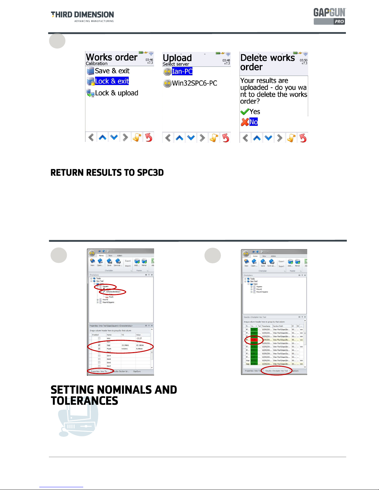
23. “Lock & exit” prepares the results to return them to SPC3D. “Save & exit” saves results if more measurements
are to be made. “Lock & upload” will upload the results to SPC3D immediately.
24. The WorksOrders shows that the Calibration checkplan is locked ready for uploading. Place the GapGun onto
the Docking Station and tap on the name “Calibration” to begin the upload.
21
22
23
24

© Third Dimension Confidential Document D13-1604-OP-EN-3.3
V7.5
13
The results from the measurements are displayed in the
Results Tab. Click on the Checkplan, Group or Feature
to see results for that selection.
Measurements that are outside the tolerances are
flagged in red for easy identification.
25. Tap “Upload” to begin uploading. Unlock will allow more results to be added to a locked Checkplan.
26. Select the SPC3D server which supplied the checkplan.
27. When the data has been sent back to SPC3D the Checkplan can be removed from the Works Orders list. Use
Download... to download the next set of Jobs.
28
25
26
27
14
© Third Dimension Confidential Document D13-1604-OP-EN-3.3
V7.5
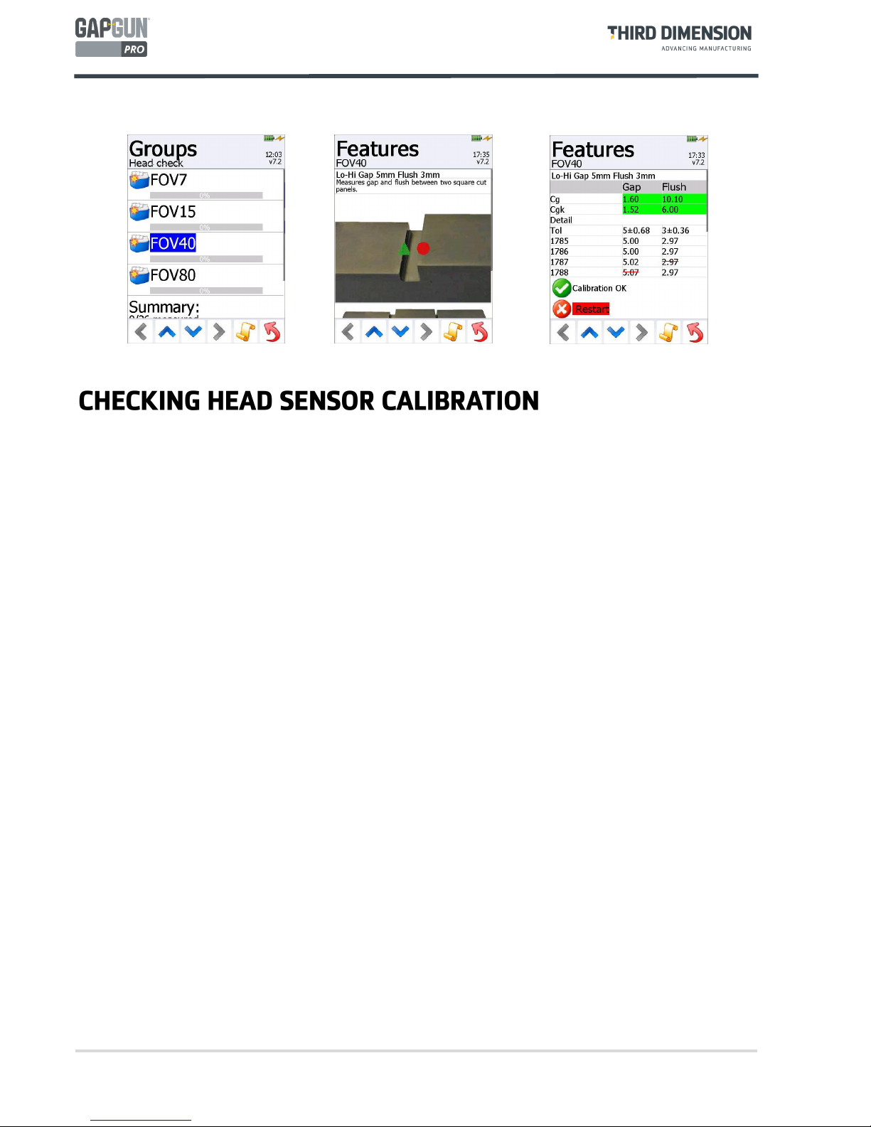
The calibration of the head can be checked by selecting the
Head Check
item at any time during measurement.
1. The Operator should then select the Group relevant to the head installed on the Gapgun.
2. Each of the features on the gauges should be tested using the up and down arrows.
3. Each measurement must be taken at least three times and the Cg and Cgk calculated. The check can be
restarted at any time by tapping Restart. Once enough successful measurements have been captured the result
is shown, in green if the calibration is okay and in red if it is out of calibration. The Operator should seek advice
on how to proceed from a Supervisor.

© Third Dimension Confidential Document D13-1604-OP-EN-3.3
V7.5
15
16
© Third Dimension Confidential Document D13-1604-OP-EN-3.3
V7.5
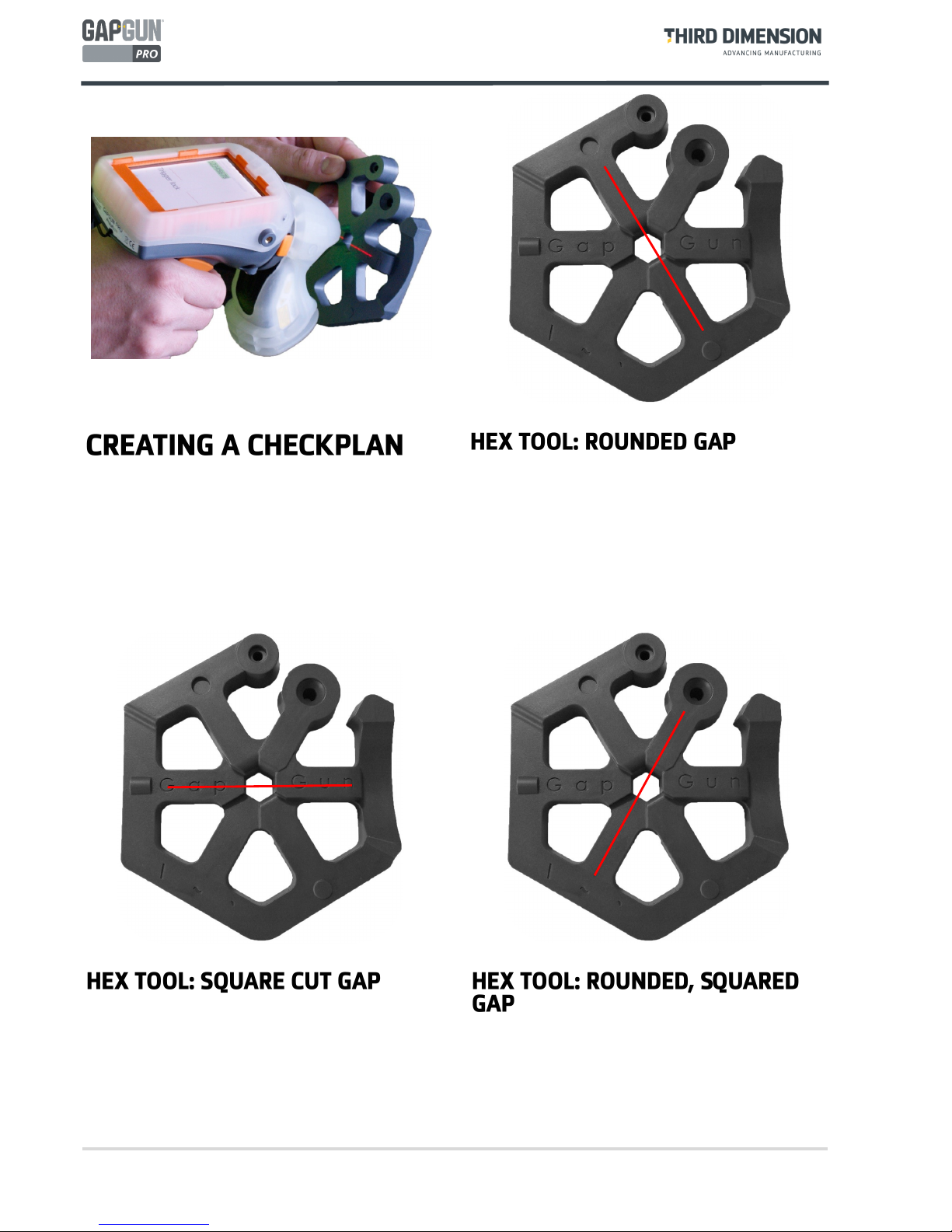
This guide demonstrates how to configure a GapGun
Checkplan to measure three Gap/Flush features on the
Hex Tool training artifact supplied with the GapGun.
The Square cut gap has square cut edges as found in
many industrial or aerospace applications, such as
panels on aircraft.
This feature has embossed lettering which shows how
the GapGun can ignore surface imperfections around
the feature when measuring.
The Hex Tool training artifact provides a wealth of
features to practice on. This guide uses three common
features.
The Rounded Gap consists of a gap and flush (step) that
have rounded edges as found on many consumer items
such as cars and white goods.
The Rounded, square gap has one side is rounded and
the other square, as found for example in automotive
ring gauges.
One side of this feature is set at an angle, to show how
the GapGun can cope with geometries that are
challenging to measure manually.

© Third Dimension Confidential Document D13-1604-OP-EN-3.3
V7.5
17
A
B
C
D
The SPC3D PC application is used to configure
Checkplans, collect measurements and configure
Features.
A. Context-sensitive command ribbon.
B. Checkplan tree view.
C. Tabbed Properties, Results and GapGuns windows.
D. Tabbed Workspace, Checkplan and Live display.
The GapGun uses a Checkplan to describe what
Features are to be measured and in what order.
Features can be put into Groups so that related
measurements can kept together.
The first step is to create a new Checkplan and give it a
descriptive name ‘Hex’.
A Checkplan can have one or more Groups, for example
grouping Features on one part of the object. A Group
can be copied to create repeating sets of Features or
mirrored to create a Group for the opposite side of the
object.
Add a Group to the Checkplan and give it a descriptive
name ‘Gaps’.
1
2
SPC3D is used to define the checkplan and configure the
features that are to be measured. These are combined
into a Works Order which is downloaded to the GapGun
to tell the operator what to measure and where to
measure each feature.
The measured results are then returned to SPC3D to be
stored and formatted for further processing.
Checkplan
Feature 1
Feature 2
Feature 3
Group 1
Group 2

18
© Third Dimension Confidential Document D13-1604-OP-EN-3.3
V7.5
Feature describes the measurement of a feature on a
part. This can have multiple measurement values, for
example Gap and Flush.
Add three Features:
Rounded - set the link to \Tools\GapFlush\PanelRad
Square - set the link to \Tools\GapFlush\PanelGF
RndSq - set the link to \Tools\GapFlush\CRV_SQR
Markers can be added to indicate which way to aim the
GapGun. The triangle indicates the left side and the
circle indicates the right, these symbols are also etched
onto the sides of the GapGun head.
The Plus, Cross and Done buttons can be used to
manage user-defined markers.
A picture of the feature can be added so that the
operator knows the precise location of the feature and
how to orientate the GapGun.
Right-click the Feature name and click on “Define
Instruction graphic…”
Select a graphic from the left hand panel or click on
the Green Plus button to import a new picture. Delete
graphics using the Cross Button or click the ‘None’
button to remove the graphic from the Feature.
4
5 6
3

© Third Dimension Confidential Document D13-1604-OP-EN-3.3
V7.5
19
7
It is recommended that the Checkplan is saved before
downloading to the GapGun this will make reviewing
measurements easier later on.
Select the Checkplan tab in the workspace then click the
Save icon on the ribbon or right-click the Checkplan
name and select Save.
8
Place the GapGun onto the Docking Station.
The GapGun will show the GapGun locating the SPC3D
host.
If Wi-Fi has been configured the GapGun will already be
connected.
To download a Checkplan to the GapGun it must first
be opened in SPC3D.
Select Open from the ribbon and select the required
Checkplan file. These files can be freely copied, emailed
or renamed.
On the GapGun the checkplan becomes a Works Order
which tells the operator what to measure.
The Operator Guide describes how to download the
Checkplan onto the GapGun and return the results.
10
9

20
© Third Dimension Confidential Document D13-1604-OP-EN-3.3
V7.5
By default, a Works Order gives a list of five Jobs to perform. This allows you to make measurements on five
separate parts (or five times on the same part.) For each Job just pulling the trigger will take you through the
menus in the right sequence.
Pull the trigger to enter the selected Job.
Enter the serial number of the part to be measured in this Job.
There is only one group in our checkplan so select this Group.
Pull the trigger to measure each Feature using the following steps.
The measurements must always be made in the same orientation so that the sign of the flush is the same.
When measuring as shown the flush will be negative, but when measured the other way round it will be
positive.
Take the measurement as described in the operator manual.
The GapGun will display the dimensions of the gap and flush measured. If the GapGun reports ERR11 then
the wrong tool is being used, ERR13 indicates that the GapGun is no being held stably enough to get good
images.
11
12
© Third Dimension Confidential Document D13-1604-OP-EN-3.3
V7.5
21
.
The nominal value (and tolerances) can also be set from
engineering drawings. Select the Feature, expand the
tree then select Characteristics.
In the Properties tab locate the Characteristics being
measured and enter the nominal and tolerance values.
Once all the measurements have been taken then use the Back button to get to the Save & exit menu.
If the GapGun is connected to the network the select Lock and Upload to return the results to SPC3D
Otherwise, Lock & exit prepares the results to be upload later when the GapGun has been connected to
SPC3D.
Once the nominals and tolerances have been set, the
Results tab will show values which are in and out of
tolerance as soon as the results are uploaded from the
GapGun.
14
15
13

22
© Third Dimension Confidential Document D13-1604-OP-EN-3.3
V7.5
Now the Checkplan has the nominal and tolerance
values set, the Checkplan is ready for use.
Select the Checkplan workspace and then save the
Checkplan or right-click the Checkplan name and select
Save.
16
To use the new Checkplan open it in SPC3D, place the
GapGun onto the Docking Station and download it or
connect to Wi-Fi and download it wirelessly.
Measure the Hex Tool against the nominals and
tolerances defined, and upload the measured data to
SPC3D.
17
Create a Checkplan to measure the radius on the
rounded gap by experimenting with different tools to
see what they do.
Right click on one the rounded gap Feature and select
Properties, then change the Link combo box to try
different ways of measuring.
Use the techniques described to measure another
object such as a car body, or an airframe.. The
principles are the same.

© Third Dimension Confidential Document D13-1604-OP-EN-3.3
V7.5
23
Characteristic
A measurement to be made of an object, for example, gap, flush, radius, angle,
depth, height, width, roughness, chamfer, burr, proud. A feature will typically have
a number of characteristics measured.
Checkplan
A set of Groups which describe the list of features which need to be measured on
an object.
Feature
A feature is a point on an object that is to be measured. It can have a number of
measurements depending on what characteristics are to measured,
e.g. Gap and Flush
FOV7, FOV15,
FOV40, FOV80
The GapGun can have a number of different heads to measure different sized features. The FOV, Field Of View defines the length of the feature to be scanned in
millimetres.
GapGun Pro
GapGun Pro is an improved highly flexible and configurable handheld measurement system designed to deliver enterprise level product build quality checks.
GapGun MX+
GapGun MX+ is a flexible and configurable handheld measurement system designed to deliver enterprise level product build quality checks.
Hex Tool
A demonstration artefact which exhibits all of the pre-defined tools measured by
the GapGun Virtual Tools library.
Group
A set of related Features, for example the features to be measured on one side of
an object. A second Group could be added for a similar object or mirrored to measure the other side of an object.
Object
The object is the target of the measurements. It may have multiple features that are
to be measured.
e.g. The Hex Tool has 21 features that can be measured.
SPC3D
PC based application software to create Checkplans, to manage delivery of Works
Orders to GapGuns, to retrieve measurements made and to customize Virtual
Tools.
Standoffs
To improve reliability and repeatability, standoffs can be used to help the operator
place the GapGun in the optimal position for accurate measurement. Customized
standoffs can be constructed for particular user requirements.
Virtual Tool
The GapGun can measure a number of dimensions of a feature, for example, the
gap between two panels and the flush height difference between the panels. The
GapGun comes with a set of pre-defined Virtual Tools to measure a wide variety of
features. They are organised into Tool families: Angle, Edge, GapFlush, Position,
Radius, Rivet, Seal, Surface and Custom. These tools are described in the Tools Appendix.
Works Order
One or more Checkplans downloaded to a GapGun to allocate a series of measurements to be made on one or more objects by this GapGun. When the Works Order
is complete, the results are be uploaded to SPC3D.

24
© Third Dimension Confidential Document D13-1604-OP-EN-3.3
V7.5
GapGun Pro Wi-Fi Data Sheet
Third Dimension Software Ltd affirms, that the equipment manufactured by the Company fulfils the
requirements of directives listed below.
Manufacturer
Third Dimension Software Ltd.
Contact
Details
Unit 3 Brabazon Office Park, Bristol. BS34 7PZ England
Tel. +44 (0)3333443000
Fax. +44 (0)3333440041
Email: info@third.com
Equipment
Control system for measurement of physical dimension using GapGun
measurement sensor.
Trade Name
GapGun Pro
Model
GG14-0067
Overview
Third Dimension is a world leading developer and manufacturer of non-contact, precision profile
measurement solutions.
Third Dimension has a long track record of supplying metrology equipment and services to the
largest names in aerospace, automotive and energy sectors worldwide.
The GapGun is a laser gauge, profile measurement system that quickly and accurately quantifies
local features such as gap and flush, step, weld and mismatch, radii, scratches, seals, dents, rivets
and fasteners. It is a proven technology, used worldwide by most major automotive and aerospace
OEMs.
The GapGun takes conventional laser scanning a step further by not only scanning a surface to
record its shape, but also automatically analysing the information to pick out specific dimensions
(gap, flush, angle, etc) and then comparing these against tolerance bands. The measured data is then
recorded for statistical process control or traceability purposes.
Providing a fully auditable trail of every single product that is measured, GapGun removes risk by
proving the quality of manufacture and in turn providing significant time and cost savings for our
customers.

© Third Dimension Confidential Document D13-1604-OP-EN-3.3
V7.5
25
Typical Application
Features/Benefit
With greatly improved speed, ease of use, portability and ruggedness, the GapGun Pro measures gap
and flush, radius, edge break, burr, countersink, scratch, weld, seal, angle and more, as the ultimate
quality inspection tool.
Ultra fast processing capability – The GapGun Pro's new, superfast processor means that
measurements can be collected faster than ever before, with speed improvements of up to 20x over
manual techniques, reducing cycle time and increasing efficiency
New VChange sensor system – GapGun Pro includes Third Dimension's ergonomic new VChange
sensor interface, which allows the sensor to remove, change and reattach sensors, in just seconds,
making multiple sensor use on the shop floor easier than ever. A vast range of measurements can be
collected using just one system and Third Dimension's extensive range of interchangeable VChange
sensors.
Fully integrated Wi-Fi – The integrated Wi-Fi connection of the GapGun Pro means instant results
access direct to the PC, with no additional hardware or cables required, giving operators total
autonomous measurement capability. This also allows for enhanced portability and convenience on
the shop floor.
Extra high capacity internal battery – GapGun Pro can operate completely standalone for around
four hours, plus a further 6.5 hours by simply attaching it to a light weight interchangeable clip on
battery pack.
Robust construction – GapGun Pro’s evolved, rugged design makes it durable for a wide range of
challenging and unique manufacturing environments
High definition colour touch screen – With 4x resolution of that on the GapGun Plus Series, this
screen is clear, highly responsive, easy to navigate and readable in a huge array of conditions.

26
© Third Dimension Confidential Document D13-1604-OP-EN-3.3
V7.5
Features
Standards Conforms to 802.11a/b/g/e/i/h/j, drafts 802.11k/r, and single-stream 802.11n standards
Frequency Band 2.4GHz & 5GHz
Security Supports WPA/WPA2 (802.11i)
Quality of Service Supports 802.11e and WMM
Antenna Internal only (InSide WLAN)
Operating Temperature 0-40oC (32-104oF)
Dimensions (W x D x H) 90 x 135 x 190mm (3.5 x 5.3 x 7.5”)
Networking and Security
Security
WEP64/128, TKIP, AES (CCMP), WPA-EAP-TLS, WPA-PSK, WPA2-EAP-TLS, WPA2
-PSK
Channels
2.4 GHz channels: 1-13
5 GHz channels: 36-140 (U-NII Band 1, 2, 2e)
Wireless LAN
Standard 802.11
Radio Redpine Signals RS9110 + Airoha 8230
RF output power 2.4 GHz
802.11b (DSSS): +17dBm (typ.)
802.11g (OFDM): +15dBm (typ.)
802.11n (OFDM): +15dBm (typ.)
RF output power 5 GHz
802.11a (OFDM): +9dBm (typ.)
802.11n (OFDM): +9dBm (typ.)
Output frequency 2.4 GHz
2.412 - 2.462 GHz, channel 1 - 11 (FCC domain)
2.412 - 2.472 GHz, channel 1 - 13 (ETSI, TELEC domain)
5 MHz channel separation
Output frequency 5 GHz
5.180 - 5.240 GHz, U-NII-1 / Channel 36, 40, 44, 48 (FCC, IC, ETSI domain)
5.260 - 5.320 GHz, U-NII-2 / Channel 52, 56, 60, 64 (FCC, IC, ETSI domain)
5.500 - 5.700 GHz, U-NII-2e / Channel 100, 104, 108,112, 116, 120, 124, 128, 132, 136,
140 (FCC, ETSI domain)
5.500 - 5.700 GHz, U-NII-2e / Channel 100, 104, 108,112, 116, 132, 136, 140 (IC domain)
5.745 - 5.825 GHz, U-NII-3 / Channel 149, 153, 157, 161, 165 (FCC domain)
TPC and DFS slave/client operation on 5.260 - 5.320 GHz, 5.500 - 5.700 GHz
20 MHz channel separation
Data Rates 20 Mbps
Modulation
DSSS (BPSK, QPSK, CCK) for 802.11b
OFDM (BPSK, QPSM, 16QAM, 64QAM) for 802.11 g/n
Transmit Power 20dBm
Receiver Sensitivity -69 dBm to -89dBm across the frequency range
Power Requirements
Supply Voltage 12V dc
Charger Voltage 240V/110V ac
Regulatory Approvals
FCC (US) Yes
IC (Canada) Yes
CE/ETSI (Europe) Yes
C-TICK (Australia) No
Telec (Japan) Yes

© Third Dimension Confidential Document D13-1604-OP-EN-3.3
V7.5
27
Safety
BS EN 60825-1:2014- Safety of laser products
BS EN 60950-1:2006+A12:2011 – Information technology equipment safety.
Declaration
General
The conformity to mentioned standards of each manufactured unit is ensured according our quality
control standards BS EN ISO9001:2008.
Europe
The placement of the CE marking on our product Third Dimension Software Ltd is declaring, on its
sole responsibility, conformity with all of the legal requirements to achieve CE marking. Third
Dimension Software Ltd is thus ensuring validity for that product to be sold throughout the
European Economic Area (EEA).
USA (FCC)
This device contains : FCC ID: PVH0941
This device complies with Part 15 of the FCC Rules. Operation is subject to the following two
conditions:
this device may not cause harmful interference, and
this device must accept any interference received, including interference that may cause
undesired operation.
This equipment has been tested and found to comply with the limits for a Class B digital
device, pursuant to Part 15 of the FCC Rules. These limits are designed to provide
reasonable protection against harmful interference in a residential installation. This
equipment generates, uses and can radiate radio frequency energy and, if not installed and
used in accordance with the instructions, may cause harmful interference to radio
communications. However, there is no guarantee that interference will not occur in a
particular installation. If this equipment does cause harmful interference to radio or television
reception, which can be determined by turning the equipment off and on, the user is
encouraged to try to correct the interference by one or more of the following measures:

28
© Third Dimension Confidential Document D13-1604-OP-EN-3.3
V7.5
Reorient or relocate the receiving antenna.
Increase the separation between the equipment and receiver.
Connect the equipment into an outlet on a circuit different from that to which the
receiver is connected.
Consult the dealer or an experienced radio/TV technician for help.
Canada (IC)
This device contains : IC ID: 5325A-0941
Operation is subject to the following two conditions:
this device may not cause interference, and
this device must accept any interference, including interference that may cause undesired
operation of the device.
Son utilisation est soumise aux deux conditions suivantes:
Cet appareil ne doit pas causer d’interférences et
il doit accepter toutes interférences reçues, y compris celles susceptibles d’avoir des effets
indésirables sur son fonctionnement.
This device complies with Industry Canada licence-exempt RSS standard(s). Under Industry Canada
regulations, this radio transmitter may only operate using an antenna of a type and maximum (or
lesser) gain approved for the transmitter by Industry Canada.
To reduce potential radio interference to other users, the antenna type and its gain should be so
chosen that the equivalent isotropically radiated power (e.i.r.p.) is not more than that necessary for
successful communication.
The device for operation in the band 5150-5250 MHz is only for indoor use to reduce the potential
for harmful interference to co-channel mobile satellite systems; the maximum antenna gain
permitted for devices in the bands 5250-5350 MHz and 5470-5725 MHz shall comply with the e.i.r.p.
limit; and the maximum antenna gain permitted for devices in the band 5725-5825 MHz shall comply
with the e.i.r.p. limits specified for point-to-point and non point-to-point operation as appropriate.
Operation in the 5600-5650 MHz band is not allowed in Canada. High-power radars are allocated as
primary users (i.e. priority users) of the bands 5250-5350 MHz and 5650-5850 MHz and that these
radars could cause interference and/or damage to LE-LAN devices.
This equipment complies with IC RSS-102 radiation exposure limits set forth for an uncontrolled
environment.
This equipment should be installed and operated with minimum distance 20cm between the
radiator & your body.
Conformité aux normes d’IC Cet appareil est conforme à la(aux) norme(s) RSS sans licence d’Industry
Canada.

© Third Dimension Confidential Document D13-1604-OP-EN-3.3
V7.5
29
Son utilisation est soumise aux deux conditions suivantes :
Cet appareil ne doit pas causer d’interférences et il doit accepter toutes interférences
reçues, y compris celles susceptibles d’avoir des effets indésirables sur son fonctionnement.
Conformément aux réglementations d’Industry Canada, cet émetteur radio ne peut
fonctionner qu’à l’aide d’une antenne dont le type et le gain maximal (ou minimal) ont été
approuvés pour cet émetteur par Industry Canada.
Pour réduire le risque d’interférences avec d’autres utilisateurs, il faut choisir le type d’antenne et
son gain de telle sorte que la puissance isotrope rayonnée équivalente (p.i.r.e) ne soit pas supérieure
à celle requise pour obtenir une communication satisfaisante.
Le dispositif de fonctionnement dans la bande 5150-5250 MHz est réservé à une utilisation en
intérieur pour réduire le risque d'interférences nuisibles à la co-canal systèmes mobiles par satellite,
le gain d'antenne maximal autorisé pour les appareils dans les bandes 5250-5350 MHz et 5470-5725
MHz doit se conformer à la pire limite, et le gain d'antenne maximal autorisé pour les appareils dans
la bande 5725-5825 MHz doivent être conformes avec le pire limites spécifiées à point-à-ponctuelles
et non point-à-point de fonctionnement selon qu'il convient.
Opération dans la bande 5600-5650 MHz n'est pas autorisée au Canada. Haute puissance radars sont
désignés comme utilisateurs principaux (c.-àutilisateurs prioritaires) des bandes 5250-5350 MHz et
5650-5850 MHz et que ces radars pourraient causer des interférences et / ou des dommages à
dispositifs LAN-EL.
Cet équipement respecte les limites d’exposition aux rayonnements IC RSS-102 définies pour un
environnement non contrôlé. Il doit être installé et utilisé en maintenant une distance minimum de
20cm entre le radiateur et votre corps.
Japan (TELEC)
204-310004
Specified radio equipment such as wireless LAN and business purpose radio used in Japan is required
to conform to the technical standards regulated by the Ministry of Internal Affairs and
communications (MIC) of Japan.
Technical regulations conformity certification is to certify that the specified radio equipment
conforms to the technical standards under the Radio Law of Japan.
The specified radio equipment as defined as the radio equipment used for small-scale radio station
specified in the Ordinance of Technical Regulations Conformity Certification of Specified Radio
Equipment.
The following three pages contain the TELEC test certificate.

30
© Third Dimension Confidential Document D13-1604-OP-EN-3.3
V7.5

© Third Dimension Confidential Document D13-1604-OP-EN-3.3
V7.5
31

32
© Third Dimension Confidential Document D13-1604-OP-EN-3.3
V7.5

© Third Dimension Confidential Document D13-1604-OP-EN-3.3
V7.5
33
Certificate Release
Issued: 12th March 2015
Third Dimension Software Ltd.
Signed:
Steve Robinson, Principal Engineer
This declaration has been issued under the sole responsibility of Third Dimension Software Ltd.
 Loading...