

Page 1

ModuLam
130
Dry-film Lamination
Engine
Think & Tinker, Ltd.
Page 2

Table of Contents
Safety First............................................................................................................................................1
Characteristics......................................................................................................................................2
Control Panel........................................................................................................................................3
Functions and Operation ......................................................................................................................4
A. Indicator lamps ..............................................................................................................................4
B. Preset functions..............................................................................................................................5
C. Temperature Control......................................................................................................................6
D. Motor / Speed Control....................................................................................................................6
Operation..............................................................................................................................................7
Cold Lamination.................................................................................................................................7
A. Cold laminating when the ModuLam is first turned on...............................................................7
B. Cold laminating with a hot machine............................................................................................7
Hot lamination....................................................................................................................................7
A. Hot laminating when the ModuLam is first turned on .................................................................7
B. Shutting down after hot lamination.............................................................................................8
Laminating Temperature and Speed....................................................................................................8
A. Adjusting laminating speed to compensate for changes in the thickness of the film or substrate..8
B. If the combination of film and paper is thinner than 1 step or thicker than 4 steps, adjust the
laminating temperature using the following chart............................................................................8
Change of step according to temperature.....................................................................................8
Tips for achieving perfect lamination..................................................................................................9
Appendix.............................................................................................................................................10
Laminating Photoresist and Soldermask............................................................................................10
Lamination Record and Setting Guide............................................................................................... 14
Specifications ......................................................................................................................................15
Page 3

Safety First
Before using your Composer laminator, there are a few precautions that should be observed.
1. To prevent the possibility of electrical shock, do not operate near sinks, bathtubs, etc.
2. Always check the electrical requirements printed on the bottom of your laminator before
plugging into a wall outlet.
3. If an extension cord or "outlet expander" is used, check its power rating to insure that it is
compatible with the requirements of the laminator.
4. Do not use the unit if the power cord or case is damaged in any way.
5. Do not allow the power cord to touch hot surfaces.
6. Turn the power off when the unit is not in use, unattended or not intended to be used.
7. Do not rest anything (including your hand) on top of the unit when it is in operation as it can get
quite hot.
8. Do not operate machine around inflammable liquids.
9. Do not allow water to enter the machine. If a drink is spilled into the unit, unplug the power cord
from the wall and allow the liquid to dry before using the laminator again.
10. Do not force substrates through the machine. You may damage the rollers and void your
warranty.
ModuLam 130 Operators Manual page 1
Page 4

Characteristics
Uniformity of
lamination
High
performance
Safety
Power saving
Soft-touch
©
control panel
Each Think & Tinker lamination engine is equipped with 6 Ceracon©
internally heated rollers. The front two rollers are act as pre-heaters,
raising the temperature of the laminating film to a temperature just
below the melting point of the adhesive. They also serve to squeeze
out any trapped air. The second pair of rollers is heated to the adhesion
fusion temperature, laminating the film to the substrate uniformly,
without voids or air pocket. The final pair of rollers are unheated and
serve to tension the laminated material as it is cooling to insure a flat,
stress free end product.
The custom microprocessor based lamination controller offers precise
digital control of both the lamination temperature and the motor speed.
Four pre-programmed combinations of speed and temperature reduce
the task of setting up the laminator to pressing a button and waiting for
the rollers to come up to operating temperature.
The laminator shell is constructed of heat resistant, non-flammable
plastic, protecting the user from the hot lamination elements and any
danger of electric shock.
The digital lamination controller insures that only the right amount of
heat is delivered to the lamination rollers, saving considerable energy
over other pouch style laminators that use switch type thermostats. The
use of a dc pulsed drive motor minimizes motor heating, resulting in
further energy savings.
All functions are controlled by depressing the desired Soft -touch
button. Signal lights and an audible alarm provide immediate feedback
that the operating parameters have been changed. An over temperature
alarm alerts the operator that the lamination temperature for the target
film has been exceeded and the user should wait until the unit cools
down.
©
ModuLam 130 Operators Manual page 2
Page 5
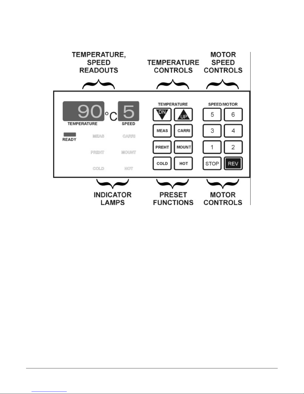
Control Panel
ModuLam 130 Operators Manual page 3
Page 6

Functions and Operation
Soft-touch© Control Panel
A. Indicator lamps
Specific lamps are illuminated to indicate the state of one or mo re of the operating parameters of the
laminator.
Temperature Indicator – displays the target operating temperature. Also used to
display the current fusion roll temperature when the MEASURE function is selected.
Roller Speed Indicator – displays the current “running speed” of the lamination
rollers
COLD
MEAS
PREHT
HOT
Indicates that the current chosen pre-set function is COLD (room temperature)
lamination. (temp. = RT , speed = 2 )
Indicates that the MEASURE (MEAS) function has been selected and the
temperature indicator is displaying the current temperature of the fusion rollers.
Indicates that the PRE-HEAT (PREHT) function has been selected. (temp. = 80°C,
speed = 2 )
Indicates that the HOT function has been selected. (temp. = 90°C, speed = 5)
MOUNT
CARRI
READY
Indicates that the MOUNTING (MOUNT) function is selected. (temp. = 130°C,
speed = 1)
Indicates that the MATTING (MOUNT) function is selected. (temp. = 110°C, speed
= 2)
Indicates the state of the rollers. Changes state according to the temperature of the
rollers as follows:
OFF – the temperature of the fusion rollers is below the set point
BLINKING – the temperature of the fusion rollers is above the set point
ON – the temperature of the fusion rollers is at the set point (+/- 3°C)
ModuLam 130 Operators Manual page 4
Page 7

B. Preset functions
A number of pre-programmed combinations of temperature and roller speed are accessible from the
control panel. These should provide good starting points when laminating new materials and will
shorten the learning curve as you familiarize yourself with ModuLam laminators.
Can be used for laminating materials that do not require heat (e.g. pressure sensitive
adhesives. A speed = 0 and temperature = 0 (room temperature) are input intot he
controller when this function is selected.
Automatically selected when laminator is first turned on.
This function is configured for applying 40 micron to 80 micron, low temperature
protective laminating film to copier bond or ink-jet media. (temp. = 90°C, speed = 5)
Configured for laminating card stock up to 2 mm thickness with protective films up to 100
microns thick. (temp. = 130°C, speed = 1)
This function is designed for laminating printed circuit substrates with dry-film
photopolymers in a siliconized carrier. Can also be used for laminating photographs with
matting film. (temp. = 110°C, speed = 2)
This is a stand-by function that can be selected when the machine will be idle for a period
of time. The lower temperature extends the life of the rollers and reduces energy
consumption. (temp. = 80°C, speed = 2 )
ModuLam 130 Operators Manual page 5
Page 8
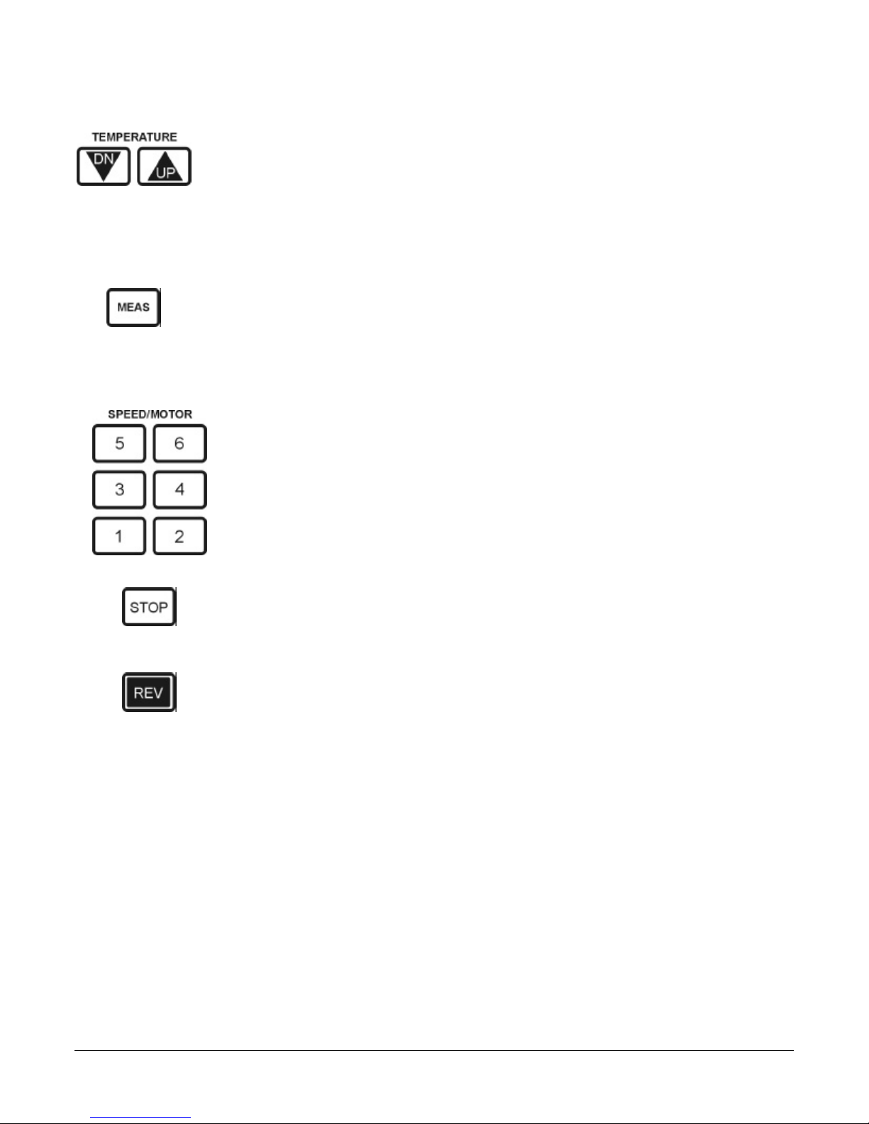
C. Temperature Control
1. The se buttons are used to increase and decrease the temperature set-point. As
might be expected, the UP arrow increases the temperature, the DOWN (DN)
arrow lowers it. After changing the temperature, allow at least 10 minutes for the
laminator to reach equilibrium.
2. The range that the temperature can be adjusted is from room temperature (RT) to
160°C in increments of 1°C. If the actual temperature exceeds 160°C (overshoot),
a warning beep will sound and the heat will automatically be reduced.
• Press the MEASURE (MEAS) button to display the current temperature of the
fusion rollers. The temperature will be displayed for 3 seconds before the
displays reverts to the set-point.
D. Motor / Speed Control
The speed of the rollers can be adjusted in 6 increments using these buttons (1
being the slowest, 6 the fastest). It is a good idea to record both the temperature
and the motor speed for each type of film that you use. The accuracy of the
Think & Tinker lamination controller allows you to return to the same operating
parameters with the touch of a couple of buttons.
This momentary switch is used to turn off the drive motor. The motor will restart
as soon as the button is released. When the rollers are at operating temperature, it
is not a good idea to keep this button depressed for long periods of time as
damage to the silicone coating may result.
This momentary switch is used to reverse the rotation of the rollers. It is used to
remove jammed substrates as well as neck ties that have been dragged into the
laminator.
ModuLam 130 Operators Manual page 6
Page 9

Operation
Cold Lamination
Cold lamination relies on pressure sensitive adhesives to bond the various laminates together. It is
especially useful for laminating materials that would be damaged excessive heat.
A. Cold laminating when the ModuLam is first turned on
1. Turn on the power switch at the right rear of the machine.
2. COLD mode is automatically set. (temp. = 0, speed = 0). The COLD indicator is illuminated.
3. Set the speed to 2 or 3 manually and test your materials for secure void-free lamination. If
small void exist or if the degree of adhesion is not adequate, try adding a bit of heat (30°C to
50°C) to see if the bond improves. Even heat sensitive materials can usually withstand such
modest temperatures.
B. Cold laminating with a hot machine
1. Select COLD mode. Set the speed to 2 or 3.
2. If the temperature is above 60°C, the ready light (REDY) will blink indicating that the
temperature of the fusion rollers is above the set point. Wait until the temperature has fallen
to 30°C, before testing your materials.
Hot lamination
Hot lamination usually refers to the process of bonding materials together with the aid of a “hot-melt”
adhesive. Many popular laminating films are co-extrusions of a polymer with a high melting point
(Mylar or PET)and one with a relatively low one (polyethylene, or polypropylene) which acts as the
adhesive.
A. Hot laminating when the ModuLam is first turned on
1. Turn on the power switch at the right rear of the machine.
2. COLD mode is automatically set. Select one of the pre-set functions or manually enter the
desired speed and temperature.
3. The unit is ready to use when the READY (REDY) indicator comes on.
4. If you are using laminating pouches, place the item to be laminated inside the pouch.
5. Gently feed into the front rollers.
6. The laminated ensemble will pass through the rollers and exit from the rear of the machine.
7. Examine the laminated specimen for voids and poor conformance. If the lamination is not
satisfactory, experiment a little with the speed and temperature until the best results are
achieved.
8. Generally speaking, once satisfactory lamination is achieved, the speed can be increased (if
desired) if the laminating temperature is also raised. Play around with a few pouches until
you find the combination of roller speed and temperature that gives you the best results.
Record the operating parameters inside the back cover of this manual.
ModuLam 130 Operators Manual page 7
Page 10

B. Shutting down after hot lamination
1. After laminating with the rollers at an elevated temperature, it is a good idea to let the rollers
cool to below 60°C before turning off the power.
2. Press the COLD button. The temperature will gradually fall and the motor will keep turning.
When the temperature falls to 60°C the motor will automatically turn off.
3. Turn off the power switch.
• Selecting COLD mode and allowing the rollers to drop in temperature before turning off the
machine will significantly increase the life of the rollers.
Laminating Temperature and Speed
When yo u are laminating a low temperature heat activated protective film onto a new substrate, a good
starting point is the HOT pre-set function. With it’s combination of temp = 90°C and speed = 5, the
HOT function should give good enough results that you can easily adjust the speed and/or temperature
to achieve excellent lamination every time. The following “adjustment schedules” should help you zero
in on the best combination of speed and temperature for you particular application.
A. Adjusting laminating speed to compensate for changes in the thickness of the film or
substrate.
1. With 80 micron film as the standard, a change in 20 microns of thickness corresponds to 1 unit
step of speed. If you set up you lamination process based primarily on 80 micron film with a
given substrate, switching film thickness will require that you decrease lamination speed by 1
step from the standard speed of 5 for every 20 microns increase in film thickness.
2. With 100 micron paper as the standard, a change in 25 microns of thickness corresponds to 1
unit step of speed. If you set up you lamination process based primarily on 100 micron paper,
switching paper thickness will require that you decrease lamination speed by 1 step from the
standard speed of 5 for every 25 microns increase in paper thickness.
B. If the combination of film and paper is thinner than 1 step or thicker than 4 steps,
adjust the laminating temperature using the following chart.
Change of step according to temperature
Temp(°C)
Step -4 -2 standard +1 +2 +3 +4 +5 +6 +7 +8
Confusing? Not really. Consider the following example:
EXAMPLE: If you want to laminate 125 micron film and 150 micron paper at a temperature of 100°C
• Temp: add 1 step to go from 90°C standard to 100°C (see table above) +1
• Paper: subtract 2 speed steps to compensate for a 50 micron increase in paper thickness above
the 100 micron standard -2
• Film: subtract 2.25 steps for increasing the film thickness by 45 microns -2.25
• Total compensation is -3.75 steps. Round up to 4 steps and subtract from the standard speed (5)
to yield a final speed of 1
70 80 90 100 110 120 125 130 135 140 150
ModuLam 130 Operators Manual page 8
Page 11

Tips for achieving perfect lamination
1. Unless a siliconized carrier is used, do not use sheet film when laminating. It may become be
come jammed or stuck to he rollers.
2. Using poor quality films or pouches can cause damage to the machine
3. If the pouch or substrate is not fed straight, lines or wrinkles may appear on the film.
4. Never force a carrier or pouch into the machine. If it will not feed, for any reason, press
REVERSE and remove.
5. Never pull an item being laminated from the back of the machine. Allow the unit to feed at it’s
own rate.
6. Laminating substrates thicker than 300 microns in a sealed pouch may result in poor sealing
along the edges.
7. Always use a carrier when laminating with films less than 80 micron total (both sides) thickness.
8. If the laminated substrate is hazy or milky in appearance or exhibits poor adhesion, reduce the
speed by 1 step and run the item back through the laminator.
9. If the laminated film looks burnt, curled, or crooked, increase the speed by 1 step.
10. If the temperature is too high or the speed is too low, film can become wrapped around the
rollers and will not be seen exiting from the rear. If this happens, press REVERSE (REV) and
gently pull the film from the front of the laminator. Remove the top cover and wipe adhesive off
of the rollers AFTER THEY HAVE COOLED TO ROOM TEMPERATURE!!
ModuLam 130 Operators Manual page 9
Page 12

Appendix
Laminating Photoresist and Soldermask
The Modulam Hot Roll laminator is available with an optional foot switch and lamination carrier
that make the application of dry-film photopolymers and pressure sensitive adhesives straight
forward and very reliable.
Materials / equipment needed:
• Modulam laminator (with footswitch)
• lamination carrier (TC10-0912)
• TackyCard
• dry-film photoresist or soldermask
• copperclad
• abrasive cleanser / copper brightener (scrub cleanser)
• abrasive scrub brush
• rubber gloves, safety glasses, and an old shirt or smock
• plastic cutting board (or 12" x 24" sheet of plastic)
• Scotch
®
roller cleaner
®
tape
Procedure
1. Place your laminator on a table (or any other stable horizontal surface) such that there is
enough room behind the unit to accommodate the longest substrate (including carrier) that
you intend to laminate. Make sure the tabletop is clean and ready to use.
2. Before heating up your machine, clean the rollers using the TackyCard®. This will insure
that debris on the fusion rollers does not damage the photoresist during lamination.
3. Inspect the unit to ensure that the heat adjustment knob is set properly for your application.
Most dry-film photopolymers (e.g. Think & Tinker photoresist and soldermask) work best
if the lamination temperature is approx. 110°C (± 5°).
If you are not sure what the proper temperature is, start at the minimum setting and work
your way up until satisfactory lamination is achieved. It takes a lot longer for the laminator
to cool down than to heat up, so start with a lower temperature setting and gradually
increase it until the desired results are achieved. Always allow at least 10 minutes after
changing the temperature setting before attempting to laminate your board.
4. Use the board as a template to cut out a piece of dry-film just large enough to totally cover
the copper surface (cut two pieces for a double sided board).
5. Prepare the copperclad for lamination by carefully cleaning both sides.
6. Very slightly wet one side of the board using fine-spray plant mister. Remember. You want
the board moist, not dripping wet. If the water beads up from the surface, the board is not
clean and you should return to step 4.
ModuLam 130 Operators Manual page 10
Page 13
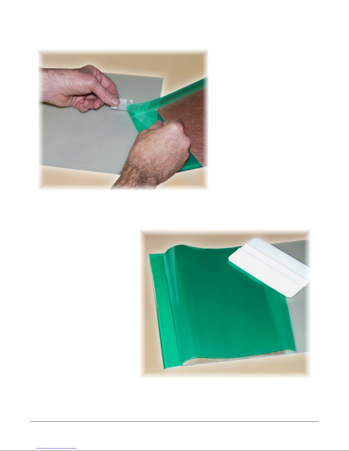
Attach two pieces of Scotch® tape
on opposite sides of one corner of
the photopolymer. Using a quick
pull, break the dull, matte release
liner away from the adhesive side
of the photopolymer (photoresist or
soldermask).
Peel back 1" of the release liner
along one edge to expose the
adhesive side of the photopolymer.
Luckily the cover sheet sticks to the
photopolymer far better than the
peel sheet so it is just about
guaranteed that pulling the pieces
of tape apart will strip the peel
sheet as desired. If the shiny Mylar
cover peels away instead, move to
another corner and try again.
Do not remove the entire liner at this time. Peeling the sheets apart generates a fair amount of
static electricity. This will, almost certainly, attract any piece of dust in your entire facility and
deposit it at the worst possible spot in your circuit pattern.
Using a soft squeegee, adhere the
entire edge of exposed adhesive to
the raised lip of the lamination
carrier.
If you are not using a carrier,
adhere the film to the leading edge
of the copperclad substrate you are
coating. Please note that you may
not be able to use this prelaminated section of the film for
circuit imaging as a result of
wrinkles and/or trapped air bubbles.
ModuLam 130 Operators Manual page 11
Page 14
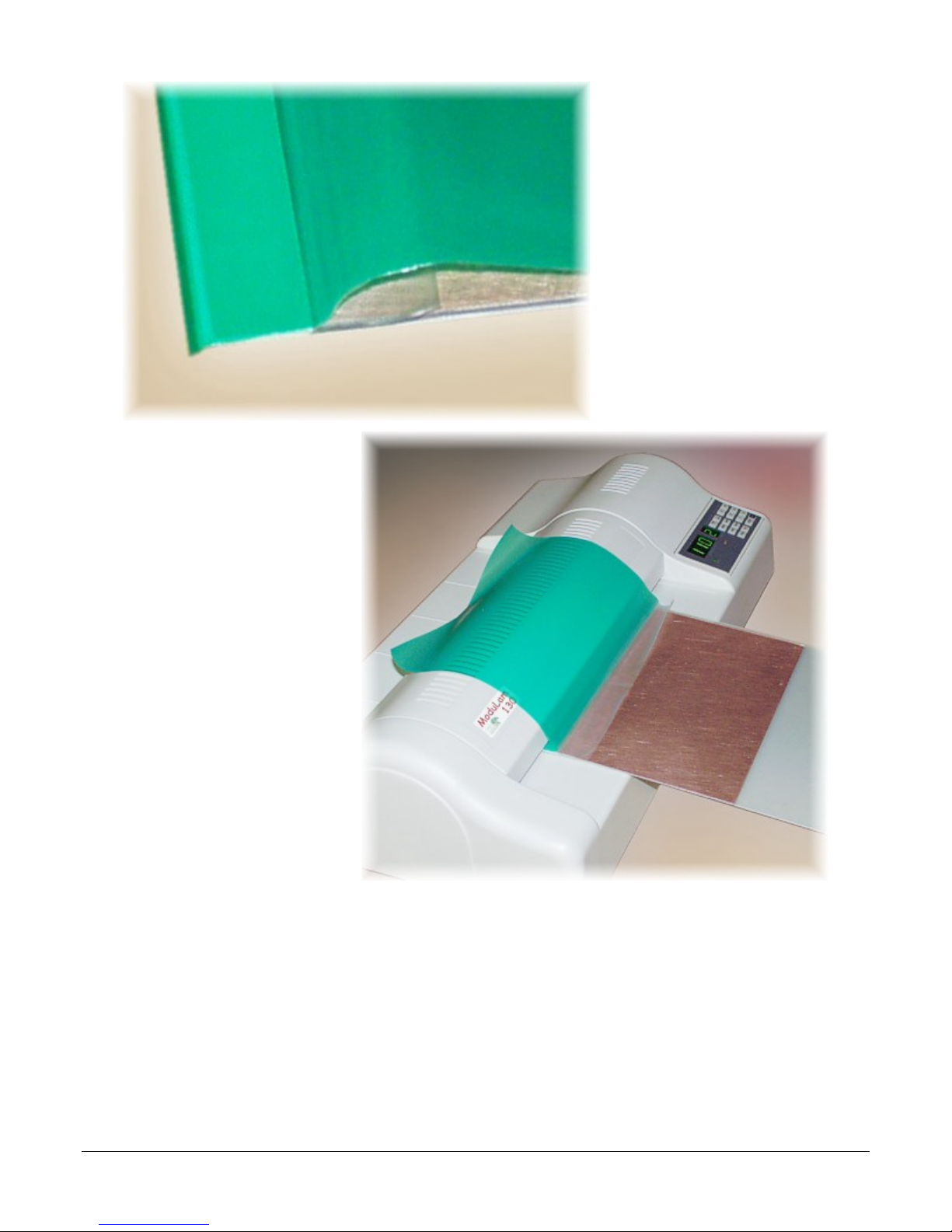
Feed the carrier (or
copperclad) into the laminator
and let about 1/2" pass
between the rollers.
Fold the stripped release liner
under the film.
If you are using a Modulam
laminator, step on the
footswitch to stop the feed
motor.
Fold the photopolymer film
back over the top of the
laminator and position the
copperclad substrate up
against the raised lip of the
carrier.
ModuLam 130 Operators Manual page 12
Page 15
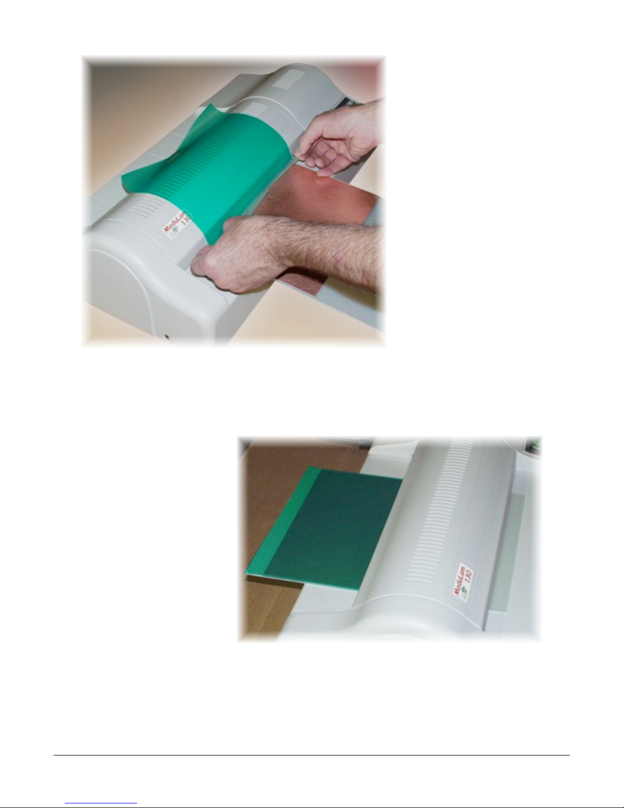
Grab the loose corners of the
release liner and pull hands
apart to apply a slight tension.
Release pressure on the
footswitch to restart the feed
motor.
As the carrier/substrate feeds
into the laminator, pull the
release liner away from the
film just fast enough to keep it
from passing into the
machine. This will apply a
mild tensio n to the film and
prevent any wrinkling or air
entrapment.
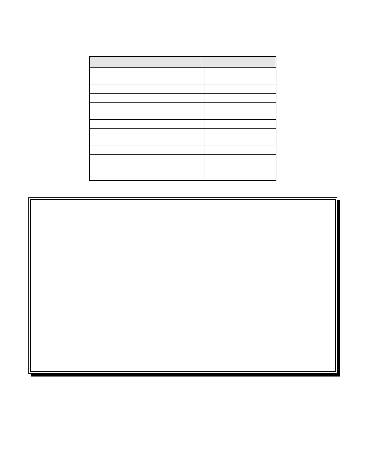
After the release liner has
pulled totally away from the
film, let the carrier/substrate
continue through the
laminator until it passes out
the other side. Use an X-Acto
knife to separate the substrate
from the carrier by cutting
along the inner edge of the
raised lip. If you are making
a double-sided PCB, flip the
substrate over and repeat the
above process on the other
side. Remember to peel off
the shiny Mylar film from the
photopolymer on the raised
lip of the carrier. This will
insure that your next
application of film will
adequately adhere.
You should remove the
photopolymer from the raised
lip of the carrier every 4 or 5
uses to prevent excessive
buildup.
ModuLam 130 Operators Manual page 13
Page 16

Lamination Record and Setting Guide
NNoo..
IItteemm bbeeiinngg
llaammiinnaatteedd
tthhiicckknneessss
((mmiillss))
ffiillmm uusseedd tthhiicckknneessss
((mmiillss))
TTeemmpp..
sseettttiinngg
Speed Carrier
used
Comments
ModuLam 130 Operators Manual page 14
Page 17
printed in USA
Specifications
ModuLam 130
Height (mm) 140
Width (mm) 580
Depth (mm) 295
Max. laminating width (mm) 330 (13")
Max. laminating speed (cm/min) 105
Max. operating temp. 140°C
Warm-up time approx. 3 min
Control system microprocessor
Drive system pulsed DC motor
Net wt. 14.1 kg
Shipping wt. 16.7 kg
Electrical 800 Watts 115/220
VAC, 50/60 Hz.
Equipment Warranty
Think & Tinker, Ltd. of Palmer. Lake, CO, USA warrants the original purchaser of this equipment to be
free from defects in material and workmanship under normal use and service. Our obligation under this
warranty shall be limited to the repair or exchange of any part or parts which may prove defective under
normal use and service within one year from the date of shipment and which our examination shall
disclose to our satisfaction to be thus defective. When necessary, purchaser shall properly pack and
return the unit to the nearest Think and Tinker Authorized Service Center, freight and insurance prepaid.
THIS WARRANTY IS EXPRESSLY IN LIEU OF ALL OTHER WARRANTIES EXPRESSED OR
IMPLIED INCLUDING THE WARRANTIES OF THE MERCHANTABILITY AND FITNESS FOR
USE AND OF ALL OTHER OBLIGATIONS OR LIABILITIES ON OUR PART, AND WE
NEITHER ASSUME NOR AUTHORIZE ANY OTHER PERSON TO ASSUME FOR US, ANY
OTHER LIABILITY IN CONNECTION WITH THE SALE OF THIS MACHINE OR ANY PART
THEREOF WHICH HAS BEEN SUBJECT TO ACCIDENT, NEGLIGENCE, ALTERATION,
ABUSE, OR MISUSE. WE MAKE NO WARRANTY WHATSOEVER IN RESPECT TO
ACCESSORIES OR PARTS NOT SUPPLIED BY US. THE TERM "ORIGINAL PURCHASER" AS
USED IN THIS WARRANTY SHALL BE DEEMED TO MEAN THE PERSON OR COMPANY
WHO FIRST PUTS THE THINK & TINKER EQUIPMENT INTO SERVICE.
MLP00-001a
ModuLam 130 Operators Manual page 15
Data subject to change without notice
© Think & Tinker, Ltd.
 Loading...