

Page 1

ThinkRF R5550
Real-Time Spectrum Analyzer
User Guide
Version 1.0
April 2019
Document no. 75-0038-190401
Copyright © 2019 ThinkRF Corporation, All rights reserved.
All product names are trademarks of their respective companies.
Page 2

Important notice
The information in this
guide is furnished for
informational use only
and is subject to change
without notice. ThinkRF
Corporation assumes no
responsibility or liability
for any errors or
inaccuracies that may
appear in this document.
No part of this
publication may be
reproduced, published,
stored in an electronic
database, or transmitted,
in any form or by any
means, electronic,
mechanical, recording,
or otherwise, for any
purpose, without the
prior written permission
of ThinkRF Corporation.
Trademarks
ThinkRF, the ThinkRF
logo and R5550 are
trademarks of ThinkRF
Corporation.
All other brand or
product names are
trademarks or registered
trademarks of their
respective companies or
owners.
ThinkRF Corp
390 March Road
Kanata, ON K2K 0G7
(613) 369-5104
HARDWARE WARRANTY AND LIMITATION OF LIABILITY
Read this warranty carefully before you use the product.
R5550 Real-Time Spectrum Analyzers are warranted for workmanship and materials
for a period of one (1) year from the date of shipment as identified by the Customer’s
packing slip or carrier waybill. ThinkRF reserves the right to void the warranty on any
equipment that has been altered or damaged due to Customer negligence,
unauthorized repair, misuse of equipment, evidence of physical or environmental
damage, transportation abuse or removal of any ThinkRF identification labels or
serial numbers.
It will remain the responsibility of the Customer, having obtained a Return Material
Authorization (RMA) and shipping instructions from ThinkRF, to return, at the
Customer's expense, the defective unit to ThinkRF’s repair facilities. ThinkRF will
incur shipping charges for the return of warranty repaired equipment. The RMA
number can be secured by calling ThinkRF Customer Service and Support (1-613369-5104). If the product does not fall within ThinkRF’s warranty period or the
product is found to be functioning as designed, then under the terms of ThinkRF’s
warranty policy, all costs of repairs and shipping will be charged directly to the
Customer. ThinkRF will warrant repaired units for a period of 90 days from date of
shipment from ThinkRF to the Customer. If the remaining period on the original
hardware warranty is greater than 30 days, then ThinkRF will honor this remaining
warranty period.
THINKRF EXPRESSLY DISCLAIMS ALL OTHER WARRANTIES AND
CONDITIONS, WHETHER EXPRESS OR IMPLIED, INCLUDING WITHOUT
LIMITATION, WARRANTIES, CONDITIONS OR REPRESENTATIONS OF
WORKMANSHIP, MERCHANTABILITY, FITNESS FOR A PARTICULAR
PURPOSE, DURABILITY, OR THAT THE OPERATION OF THE HARDWARE OR
LICENSED SOFTWARE WILL BE ERROR FREE. IN NO EVENT WILL THINKRF
BE LIABLE FOR INDIRECT, SPECIAL, INCIDENTAL, OR CONSEQUENTIAL
DAMAGES.
USE OF PRODUCTS IN HIGH RISK ACTIVITIES
THINKRF PRODUCTS ARE INTENDED FOR STANDARD INDOOR COMMERCIAL
USE. WITHOUT THE APPROPRIATE NETWORK DESIGN ENGINEERING, THEY
MUST NOT BE USED FOR ANY “HIGH RISK ACTIVITY”, as described in this
paragraph. Customer acknowledges and agrees that the products supplied
hereunder are not fault-tolerant and are not designed, manufactured or intended for
use or resale as on-line control equipment in hazardous environments requiring fail
safe performance including but not limited to the operation of nuclear facilities,
aircraft navigation or communication systems, air traffic control, direct life support
machines, or weapons systems, in which the failure of products could lead directly to
death, personal injury, or severe physical or environmental damage, all of which are
examples of “High Risk Activity”. THINKRF AND ITS SUPPLIERS EXPRESSLY
DISCLAIM ANY EXPRESS OR IMPLIED WARRANTY OF FITNESS FOR HIGH
RISK ACTIVITIES.
GNU General Public License
This device contains free firmware: you can redistribute it and/or modify it under the
terms of the GNU General Public License as published by the Free Software
Foundation, either version 3 of the License, or (at your option) any later version. This
program is distributed in the hope that it will be useful, but WITHOUT ANY
WARRANTY; without even the implied warranty of MERCHANTABILITY or
FITNESS FOR A PARTICULAR PURPOSE. See the GNU General Public License
for more details. GNU General Public License is available at
http://www.gnu.org/licenses/.
Page 3

Table of Contents
Preface ............................................................................................................................ 5
Audience ............................................................................................................................................ 5
Conventions ....................................................................................................................................... 5
Obtaining the Latest Documentation and Software ............................................................................ 5
Document Feedback .......................................................................................................................... 5
Obtaining Technical Assistance ......................................................................................................... 6
Overview of the ThinkRF R5550 ................................................................................... 7
Getting Familiar with the ThinkRF R5550 .......................................................................................... 8
The Front Panel .......................................................................................................................... 8
The Rear Panel .......................................................................................................................... 8
The Underside ............................................................................................................................ 9
Installing the ThinkRF R5550 ...................................................................................... 10
Preventing Electrostatic Discharge Damage .................................................................................... 10
Unpacking the Box ........................................................................................................................... 10
Connecting the Antenna, Ethernet and Power Cables ..................................................................... 11
Selecting Where to Mount the R5550 .............................................................................................. 12
Connecting to the R5550 ............................................................................................. 13
Deciding on Your Network Topology and IP Address Allocation ...................................................... 13
Changing the Method of IP Address Allocation for the R5550 analyzer .......................................... 14
Connecting the R5550 Analyzer Directly to a Computer .................................................................. 14
Connecting to the R5550 Analyzer Across a Network ..................................................................... 16
Administration Console .............................................................................................. 18
Connecting via Your Web Browser .................................................................................................. 18
Configuring the R5550 Time ............................................................................................................ 18
Configuring the R5550 IP Address .................................................................................................. 20
Updating the R5550's Firmware ...................................................................................................... 20
Customizing the R5550 Calibration ................................................................................................. 22
Uploading a Custom Calibration File ........................................................................................ 23
Calibration File Source Selection .............................................................................................. 24
Restoring the Default Calibration Settings ................................................................................ 24
Restarting the R5550 ....................................................................................................................... 25
Reset to Factory Settings ........................................................................................... 26
Using the USB Console ............................................................................................... 27
Installing the USB Drivers on Your PC ............................................................................................ 27
Connecting to the USB Console ...................................................................................................... 27
To Configure the R5550 Analyzer's IP Address ............................................................................... 28
Page 4

Status Indicator LEDs ................................................................................................. 30
Power-up Sequence ........................................................................................................................ 30
Power (PWR) Indicator LED ............................................................................................................ 30
Status (STS) Indicator LED .............................................................................................................. 30
10 MHz Reference (REF) Clock Source and Lock Indicator LED .................................................... 31
RF Chain PLLs LOCK Indicator LED ............................................................................................... 31
Ethernet LINK Status and ACT Indicator LEDs ................................................................................ 31
Hardware Reference .................................................................................................... 33
System Specifications ...................................................................................................................... 33
SMA Connectors .............................................................................................................................. 33
Ethernet RJ-45 Port Pinout .............................................................................................................. 34
GPIO Port Pinout ............................................................................................................................. 34
USB Console Port Pinout ................................................................................................................. 35
RJ-45 Straight-Through Ethernet Cable .......................................................................................... 36
RJ-45 Crossover Ethernet Cable ..................................................................................................... 36
Document Revision History ........................................................................................ 37
Page 5
Preface
This preface describes the audience for, the organization of, and conventions used in this
document. It also identifies related documentation and explains how to access electronic
documentation.
Audience
This document is written for technical people who have basic understanding, familiarity
and experience with network test and measurement equipment.
Conventions
This section describes the conventions used in this document.
Note: This symbol means take note. Notes contain helpful suggestions or references to
additional information and material.
Caution: This symbol means be careful. In this situation, you might do something that
could result in equipment damage or loss of data.
Warning: This symbol means danger. You are in a situation that could cause bodily
injury. Before you work on any equipment, be aware of the hazards involved with
electrical circuitry and be familiar with the standard practices for preventing accidents.
Obtaining the Latest Documentation and Software
Please regularly visit our website's resource page at http://www.thinkrf.com/resources
to obtain the latest documentation and the latest releases of new firmware and software.
Document Feedback
Please send your comments about this document or our other documentation to
support@thinkrf.com.
Thank you, we appreciate your comments.
Page 6

Obtaining Technical Assistance
The ThinkRF Support website provides online documents for resolving technical issues
with ThinkRF products at http://thinkrf.com/documentation/.
For all customers who hold a valid end-user license, ThinkRF provides technical
assistance 9 AM to 5 PM Eastern Time, Monday to Friday. Contact us at
support@thinkrf.com or by calling +1.613.369.5104.
Before contacting Support, please have the following information available:
R5550 serial number which is located on the identification label on the R5550's
underside.
The product version.
The firmware version running on the R5550.
Versions of ThinkRF software you are using, potentially including the API
libraries to third-party applications.
The operating system and version you are using.
Page 7

Overview of the ThinkRF R5550
Overview of the ThinkRF R5550
The R5550 Real-Time Spectrum Analyzer (RTSA) is a high-performance softwaredefined RF receiver, digitizer and analyzer. It is designed for stand-alone, remote,
distributed, and/or embedded real-time spectrum analysis, monitoring and intelligence
applications.
ThinkRF has patented software-defined RF receiver technology that provides industry
leading combined sensitivity, tuning range, instantaneous bandwidth and scan rate.
Additionally, the R5550 provides real-time sophisticated triggering, search and loss-less
capture of signals of interest using an integrated patented digital signal processing
engine.
The R5550 is ideal for monitoring, management and surveillance of transmitters, whether
they are in-building or spread across a geographic area. Applications include but are not
limited to spectrum analysis, 5G wireless technology, research, test and measurement,
spectrum monitoring and OEM integration.
The R5550 Real-Time Spectrum Analyzer provides Gigabit Ethernet for stand-alone,
remote and distributed applications. ThinkRF supports a rich set of industry-leading
standard protocols and APIs, enabling the R5550 to easily integrate into your new or
existing applications. Standard protocols include the Standard Commands for
Programmable Instruments (SCPI) protocol for controlling and obtaining status from the
R5550 and the VITA 49 Radio Transport (VRT) protocol for digitized data and its
associated context information. APIs are provided for interfacing and performing data
acquisition and spectral analysis with Python™, C/C++, MATLAB® and LabVIEW®
Applications can also be built within the PyRF development framework. PyRF is built on
the Python programming language and is open-source under BSD licensing. PyRF
handles the low-level details of real-time acquisition, signal processing and visualization,
and provides feature rich libraries, example applications and source code, all specific to
the requirements of signal analysis.
ThinkRF R5550 Real-Time Spectrum Analyzer User Guide 7
Page 8
Overview of the ThinkRF R5550
Getting Familiar with the ThinkRF R5550
This section provides information about the front and rear panels, connection ports and
identification label of the R5550 Real-Time Spectrum Analyzer.
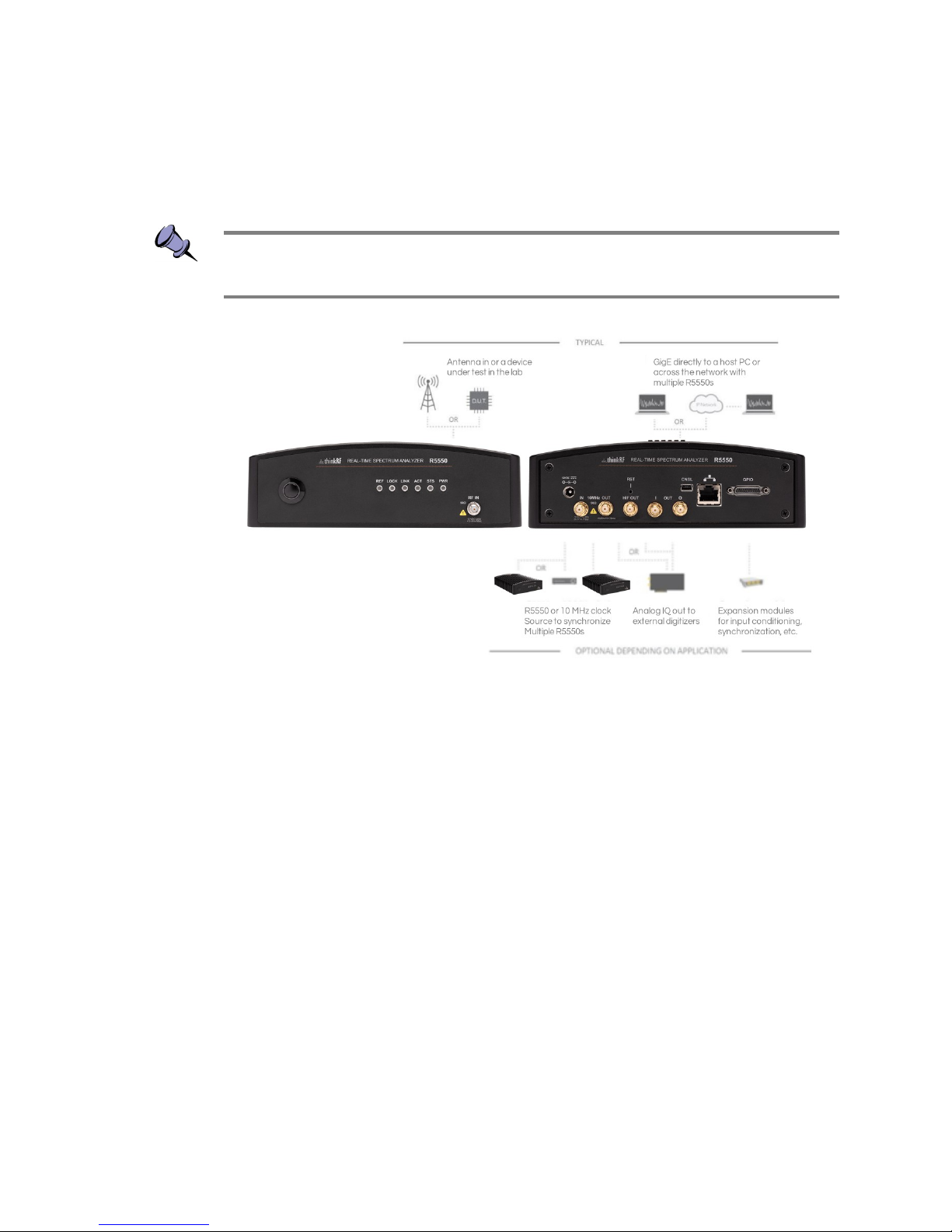
Note: The type and placement of connectors and components on the panels and the
case may vary depending upon the product variant and version.
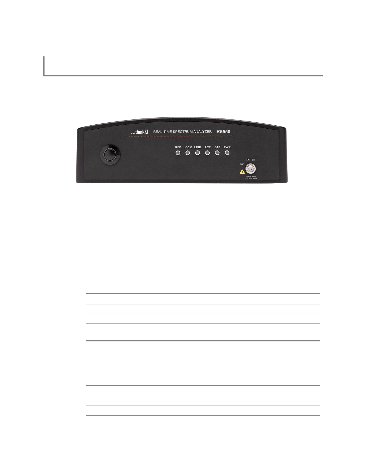
The Front Panel
The front panel of the R5550 (the left side of the picture above) contains the power
switch, status indicator LEDs and input connector for the RF antenna port.
The Rear Panel
The rear panel of the R5550 (the right side of the picture above) contains the power
input, 10 MHz reference clock I/O, hardware reset push-button, HIF output, analog I/Q
outputs, USB console (CNSL), Ethernet, and GPIO port.
8 ThinkRF R5550 Real-Time Spectrum Analyzer User Guide
Page 9
Overview of the ThinkRF R5550
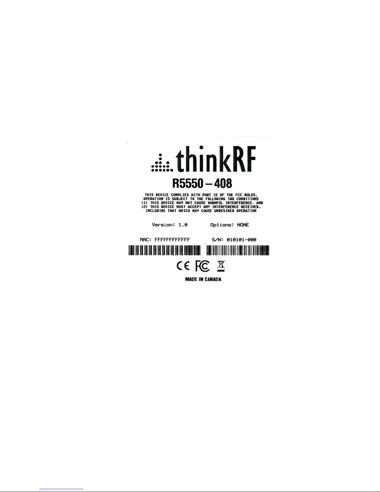
The Underside
The underside of the ThinkRF R5550 provides an identification label, as illustrated in the
following page. The label on your product may vary depending on your product variant
and version. This product “Version” number is important for identifying which firmware
can be used to update your product.
ThinkRF R5550 Real-Time Spectrum Analyzer User Guide 9
Page 10
Installing the ThinkRF R5550
Installing the ThinkRF R5550
Ensure that you read and understand the following information about safety and
electrostatic discharge before you unpack and install the R5550.
Warning: Only trained and qualified personnel should be allowed to install or replace this
equipment. Read the installation instructions before you connect the system to its power
source.
Preventing Electrostatic Discharge Damage
Electrostatic Discharge (ESD) is a single-event, rapid transfer of electrostatic charge
between two objects, such as an operator and a piece of electrical equipment. ESD can
occur when a high electrostatic field develops between two objects in close proximity.
ESD occurs when electronic components are improperly handled and is one of the major
causes of device failures in the semiconductor industry.
Electrostatic discharge is more likely to occur with the combination of synthetic fibers and
dry atmosphere. Always follow these steps to prevent ESD.
Warning: Never open the front or rear panels of the R5550 as personal injury may result
and opening the chassis will void the warranty. There are no user-serviceable parts
inside. Always contact ThinkRF support for service through the online support form at
http://www.thinkrf.com/support/.
Caution: To prevent ESD, wear an ESD-preventive wrist strap that you provide, ensuring
that it makes good skin contact.
Caution: Do not touch any exposed contact pins or connector shells of interface ports
that do not have a cable attached. If cables are connected at one end only, do not touch
the exposed pins at the unconnected end of the cable.
Unpacking the Box
The following table lists the items that come with your R5550 analyzer. If any of the items
are missing or damaged, please contact your ThinkRF customer service representative.
10 ThinkRF R5550 Real-Time Spectrum Analyzer User Guide
Page 11
Installing the ThinkRF R5550
ThinkRF R5550 Shipping Box Contents:
• R5550 Real-Time Spectrum Analyzer
• Power adapter and cable
• Straight-through Ethernet cable
• USB console cable
• Antenna
• Precautions & Quickstart Guide
Note: The antenna is included for your convenience and only intended to perform
adequately across a limited frequency range.
Connecting the Antenna, Ethernet and Power Cables
Caution: Never connect a transmitter directly to the receiver with a cable.
Caution: Do not over-tighten the antenna connector on the jack. Using a wrench, pliers
or even your hand to over-tighten the antenna can cause permanent damage to the
receiver. See SMA Connectors section for the torque recommendation.
1. Screw the antenna on to the R5550 "RF IN" antenna input SMA jack. Carefully
turn the antenna screw by hand until it encounters resistance. See System
Specifications for the maximum allowable input and cautions.
2. Connect one end of the Ethernet cable to the R5550's Ethernet port and the
other end to an Ethernet port on your router or PC.
3. Connect the R5550 analyzer to its power adapter.
Warning: Use only the power adapter provided with the unit.
4. Plug the power adapter into a power outlet.
5. Push the power switch towards the power symbol to power the unit on.
Note: See Administration Console section for description of the R5550 status.
ThinkRF R5550 Real-Time Spectrum Analyzer User Guide 11
Page 12

Installing the ThinkRF R5550
Selecting Where to Mount the R5550
Caution: To prevent damage to the R5550 radio receiver, do not install or operate the
R5550 within 2 feet (60 cm) of devices such as Wi-Fi access points that transmit more
than +15 dBm power.
12 ThinkRF R5550 Real-Time Spectrum Analyzer User Guide
Page 13

Connecting to the R5550
Connecting to the R5550
The R5550 analyzer is a network device and typically all communications with the R5550
analyzer are via a Gigabit Ethernet connection, either directly to a computer or across an
IP network. The R5550 analyzer's Gigabit Ethernet connection provides control and
status of the R5550 using SCPI commands and data using the VRT protocol.
This section provides instruction for different methods of connecting to the R5550 via its
Ethernet port and obtaining its IP address.
Deciding on Your Network Topology and IP Address Allocation
Note: To connect with the R5550 analyzer via its Ethernet port, you must decide on both
the topology of your network connection and how your R5550 obtains its IP address.
As illustrated in the following picture, the R5550 supports any IP network topology
connected via its Ethernet port including:
a direct connection to a computer across an RJ-45 Ethernet cable as per the
Connecting the R5550 Analyzer Directly to a Computer section;
a connection across a routed local network, whether on the same subnet or
across different subnets or across a routed wide-area network such as the
Internet, as per the Connecting to the R5550 Analyzer Across a Network section.
The R5550 analyzer also supports different methods of obtaining its IP address including:
dynamic IP address allocation via the Dynamic Host Configuration Protocol
(DHCP), which is applicable to a routed network topology that has a DHCP
server;
dynamic IP address allocation via the Automatic Private IP Addressing (APIPA)
protocol (otherwise known as Auto-IP), which is applicable for where a DHCP
server is not available. This method allows a direct connection to a computer that
supports Auto-IP or to a local network using a switch. With Auto-IP, a host
13 ThinkRF R5550 Real-Time Spectrum Analyzer User Guide
Page 14

Connecting to the R5550
network device randomly assigns itself a link-local address in the 169.254.x.y
subnet when it fails to contact a DHCP server. Many operating systems (OSs),
including Windows, support Auto-IP;
static IP address allocation, which is applicable to any network topology.
Changing the Method of IP Address Allocation for the R5550 analyzer
This section provides the instruction for re-configuring one IP address allocation type to
another.
Note: The R5550 analyzer is configured for dynamic IP address allocation by factory
default.
If your R5550 analyzer is configured for dynamic IP allocation, then it may be
reconfigured for static IP address allocation using either its web administration or USB
console. Using the administration console in this scenario requires first a connection to
the R5550 via its Ethernet port, which in turn requires dynamic allocation of its IP either
by DHCP or Auto-IP.
If your R5550 is configured for static IP allocation, then it may be reconfigured for
dynamic IP address allocation using its administration or USB console or via a hardware
reset. Using the hardware reset to reconfigure to dynamic IP allocation is the simplest
method and is described in the section. Using the administration console requires a
connection to the R5550 via its Ethernet port.
Connection to the R5550 using dynamic or static IP allocation is described in the
following sections. The console usage is described in the Administration Console or To
Configure the R5550 Analyzer's IP Address section.
Connecting the R5550 Analyzer Directly to a Computer
This section provides instruction on connecting the R5550 analyzer directly to a computer
via their Ethernet ports using an Ethernet cable.
In order to connect directly to a R5550, the host PC might require a spare Ethernet
interface that is not otherwise used as its primary network connection. For example, you
may use a wireless connection for primary network connectivity or obtain a second
Ethernet card or USB adapter to connect to the R5550.
For this overview, the ThinkRF S240 Real-Time Spectrum Analysis Software is used to
connect to the R5550 analyzer. The latest version of this software can be found at http://
www.thinkrf.com/resources.
To connect the R5550 directly to your computer:
1. Decide on whether you will be using static or dynamic IP allocation. Regardless
of which method you choose, both your PC's and the R5550 Ethernet interface
must be configured for the same method of IP allocation. If necessary, configure
your R5550 to your chosen method of IP allocation following the instruction in the
section.
ThinkRF R5550 Real-Time Spectrum Analyzer User Guide 14
Page 15

Connecting to the R5550
2. Connect the provided Ethernet cable to both your PC's and the R5550 Ethernet
ports.
3. Power up the R5550 and wait a minute for it to complete booting.
4. Check to ensure that either your PC's or the R5550 LINK indicator is illuminated.
If it is not then your PC may not support automatic crossover on its Ethernet
connection and you may require an RJ-45 crossover Ethernet cable as specified
in the section.
5. If you're using static IP allocation then skip to the next step. Otherwise, check the
STS LED for the Auto-IP setup completion (take a minute or longer).
Note: While the R5550 is searching for a DHCP server, the STS LED blinks yellow slowly
until it obtains an IP address either via DHCP or Auto-IP. The STS LED blinks in a green
heartbeat pattern if it has set up successfully to using an Auto-IP address.
Verify the host PC's IP configuration using the PyRF Discovery Tool. With a
Windows OS, open a Command window and type ipconfig to show the IP
addresses assigned to each interface. The Ethernet interface should show a
169.254.x.y address as seen in the following picture as an example.
6. Use the PyRF Discovery tool or the S240 Real-Time Spectrum Analysis Software
(as shown in the following figure), both provided by ThinkRF, to determine the
assigned IP address of the R5550. In order for the Discovery tool to locate the
R5550, both your computer and the R5550 must be configured for the same
subnet. If you are using Auto-IP dynamic IP allocation, then they will both be on
the same 169.254.x.y subnet. If you are using static IP and the Discovery tool
cannot locate the R5550, then you need to have prior knowledge of its static IP
address or use the USB console.
15 ThinkRF R5550 Real-Time Spectrum Analyzer User Guide
Page 16

Connecting to the R5550
7. The assigned IP address may now be used to communicate with the R5550
analyzer.
Note: Link-local addresses used for Auto-IP are non-routable, so communications is
limited to devices within the local subnet. This restriction may be an issue when running
virtual machines (e.g. Mac Parallels, VirtualBox, etc.) that may be connected through
virtual routers to the host PC's physical network interface.
Note: After obtaining a link-local address, the R5550 continues to request a DHCP
address. If a DHCP server responds at a later time, the link-local address is overwritten
with the offered IP address. This new address is retained until the network cable is
physically unplugged or the R5550 is restarted.
Connecting to the R5550 Analyzer Across a Network
This section provides instruction on connecting the R5550 to a computer across a routed
local network whether on the same subnet or across different subnets or across a routed
wide-area network such as the Internet.
To connect the R5550 across a network:
1. Decide on whether you will be using static or dynamic IP allocation. Both your PC
and the R5550 do not need to be configured for the same method of IP
allocation; although to locate your R5550 using the ThinkRF Discovery tool
requires that they be on the same subnet. If necessary, configure your R5550 to
your chosen method of IP allocation following the instruction in the section. If you
are using dynamic IP allocation then your router or your network must support a
DHCP server.
2. Connect the provided Ethernet cable to both your router's and the R5550
Ethernet ports.
3. Power up the R5550 and wait a minute for it to complete booting. The sequence
of connecting and powering on are inconsequential.
4. Check to ensure that either your router's or the R5550's LINK indicator is
illuminated.
5. If your R5550 is behind a firewall or a router with firewall capability, then your
network's DHCP server is likely assigning private IP addresses (e.g. 192.168.x.x,
10.x.x.x, 172.x.x.x), and the firewall is likely providing some form of network
address translation (NAT) function. If this is the case and if you require access to
the R5550 from outside your firewall, then you will likely have to configure the
firewall to allow port forwarding on port 37000 and 37001. If necessary, consult
with your network administrator.
6. Use the PyRF Discovery tool or the S240 Real-Time Spectrum Analysis Software
both provided by ThinkRF, to determine the R5550's assigned IP address. In
order for the Discovery tool to locate the R5550, both your computer and the
R5550 must be configured for the same subnet. If you are using DHCP then you
may have to query your router's allocation tables to determine the IP that is
allocated to your R5550 MAC address. If you are using static IP and the
ThinkRF R5550 Real-Time Spectrum Analyzer User Guide 16
Page 17

Connecting to the R5550
Discovery tool cannot locate the R5550, then you need to have prior knowledge
of its static IP address or use the USB console. If necessary, consult with your
network administrator.
7. The assigned IP address may now be used to communicate with the R5550.
17 ThinkRF R5550 Real-Time Spectrum Analyzer User Guide
Page 18

Administration Console
Administration Console
This section provides instruction on connecting to the R5550 via its web-based
Administration Console. The Administration Console provides the ability to:
obtain status information from the R5550;
change date and time configuration;
change IP configuration;
upgrade the R5550 software/firmware;
upload customized calibrations settings;
and/or restart the R5550.
All of these functions may be performed via the network either locally or remotely.
Connecting via Your Web Browser
Connect to the R5550 Administration Console by entering the IP address of your R5550
into a web browser's web address dialog. The IP address is shown in the S240 software
as the connected device. The following "Status" web page should appear providing
information on the R5550.
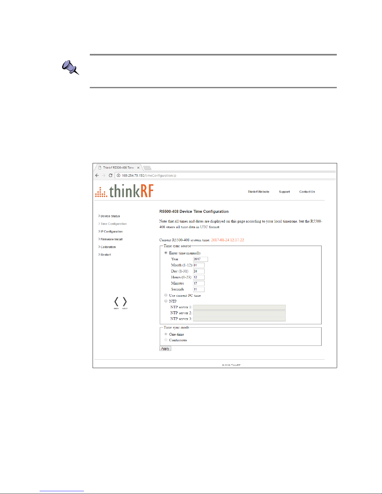
Configuring the R5550 Time
The time on the R5550 analyzer can be set manually or as per host PC's time or via an
NTP server.
ThinkRF R5550 Real-Time Spectrum Analyzer User Guide 18
Page 19
Administration Console
Note: The R5550 analyzer stores its time based on the Coordinated Universal Time
(UTC) and otherwise has no notion of local time-zones. Conversely, the web dialog
translates and displays the R5550 time based on the local time-zone setting of the PC.
1. Click on the "Time Configuration" link in the left column menu of the
administrative console web page. The following "R5550 Device Time
Configuration" web page should appear.
2. Select the time synchronization source.
3. If “Enter time manually” is selected then enter the date and time based on your
local time-zone.
4. If “Use current PC time” is selected then the data and time fields will be
populated automatically.
5. If “NTP” is selected, enter at least one NTP server IP address and select whether
the time be synced just this one time or continuously. If “continuously” is
selected, the R5550's time is synchronized to the NTP server on a continuous
and regular basis, the regularity of which is optimally determined automatically.
6. Click the “Apply” button.
19 ThinkRF R5550 Real-Time Spectrum Analyzer User Guide
Page 20

Administration Console
Configuring the R5550 IP Address
The R5550 provides options for selecting whether the R5550 IP address is obtained
dynamically using DHCP or is set manually to a static address.
Caution: Please note that if the R5550 IP address is set to static IP then the only way to
communicate with the R5550 is via that IP address. If you mistakenly enter the wrong IP
address and/or subnet mask, or forget the IP address, then you can change the IP
configuration Using the USB Console or Restarting the R5550.
1. Click on the "IP Configuration" link in the left column menu of the administrative
console. The following "R5550 Device IP Configuration" web page should
appear. Once the “Apply” is clicked, the new configuration will take effect
immediately and the current configuration and web page will no longer be valid.
Updating the R5550's Firmware
This section will step you through updating the R5550 firmware. The firmware install file
contains firmware images associated with the R5550 FPGA, Linux operating system and
the embedded application. The process of updating will copy the new images to the
R5550 in addition to and without erasing the current installed images. The new install will
only take effect upon the R5550 being restarted.
Note: Updating firmware might over-write any user-defined calibrated values, see
Customizing the R5550 Calibration for more information.
ThinkRF R5550 Real-Time Spectrum Analyzer User Guide 20
Page 21

Administration Console
1. Click on the "Firmware Install" link in the left column menu of the administrative
console. The following "Firmware Install" web page should appear.
Warning: Do not unplug the R5550 during a firmware update or the device may become
inoperable.
2. Enter or browse to the location of the "ThinkRF_R5550_firmware_vX.Y.Z.img" (or
similar *.img) firmware image file and then click the "Install" button.
When the firmware image for the intended product version is installed, the
following "Firmware Install" web page should appear which will step through the
progression of the firmware being uploaded and installed.
21 ThinkRF R5550 Real-Time Spectrum Analyzer User Guide
Page 22

Administration Console
3. Upon completion, the following web dialog box should appear. Press the "OK"
button to restart the R5550 or "Cancel" to defer restarting until a later time.
Note: If the R5550 is not restarted immediately after a firmware install process, then the
newly installed firmware will take effect upon the next restart of the R5550 regardless of
whether it is a software restart or a power-on reset.
In addition, the boot up might take over a minute when there are new changes to the
calibration setup or Auto-IP connection method is used.
Customizing the R5550 Calibration
The R5550 supports user-defined calibration settings if you do not want to use the
ThinkRF default calibration settings. This allows you to calibrate the R5550 analyzer's
RFE with reference levels based on, for examples - frequency ranges, temperature
ranges, and insertion loss of the attenuator that are specific to your own applications.
You can upload your own calibration settings through the R5550 administration console
using the instruction described in the following section.
ThinkRF R5550 Real-Time Spectrum Analyzer User Guide 22
Page 23
Administration Console
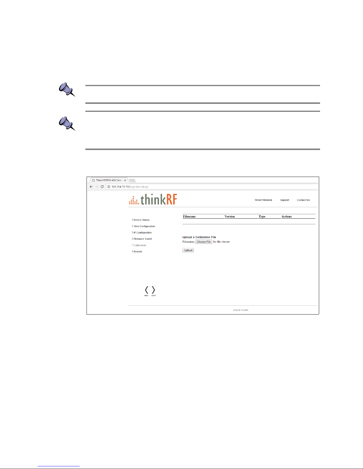
Uploading a Custom Calibration File
You can upload your custom calibration settings file to the R5550 via the administrative
console.
Note: You must restart the R5550 for the new calibration settings to take effect.
Note: Custom calibrated values might get over-written by a new firmware update. After
restarting the unit once the firmware update is done, check the Calibration tab of the
administration console to see which calibration file source is listed on the top of the
Filename list (ie. “System” or your customized file).
1. Click the "Calibration" link in the left column menu of the administrative console
web page. The "R5550 Device Calibration" page will appear.
2. Click “Browse”. An Explorer window will open on your PC.
3. Navigate to the location of the desired file and click “Open”. The selected file
name appears beside the “Browse” button in the Administration console.
4. Click “Upload”. When successful, the custom calibration file is uploaded to the
R5550 and appears in the list of calibration files. The most recent uploaded file
will be listed at the top of the table.
5. Restart the R5550 by using the administrative console or toggling the power
switch. The boot up will take longer than usual after the restart as the embedded
system applies the new calibrated values.
6. If a tag or its value is incorrectly created in the custom file, an error, when
detected, will be displayed with the appropriate message and the file will not be
uploaded. See the following picture for example.
23 ThinkRF R5550 Real-Time Spectrum Analyzer User Guide
Page 24

Administration Console
Calibration File Source Selection
When more than one calibration settings file are present in the system, the R5550 selects
the calibration source using the following priority:
1. Firmware version specified in the calibration file
2. Calibration file source with the following priority going from higher to lower:
a. User-defined file
b. ThinkRF factory defaults (from factory calibration)
c. ThinkRF system defaults (from firmware update)
3. Created date and time of the calibration file (as listed in the <created> field)
For example, if two calibration files have the same firmware version, then the file source
is compared. If the source is the same, then the created date and time is compared. The
most recent date will be used.
Any calibration data that is not specified or missing in the new calibration file will be
retrieved from the calibration file of the next highest priority.
Restoring the Default Calibration Settings
You can restore the calibration settings to system defaults at any time by deleting all
custom calibration files from the system. You will not be able to delete the system
calibration file.
1. In the "R5550 Calibration Upload" page, select a custom calibration file from the
list and click “DELETE” in the Actions column.
2. Repeat step 1 for all custom calibration files on the system.
ThinkRF R5550 Real-Time Spectrum Analyzer User Guide 24
Page 25

Administration Console
3. Restart the R5550 either by using the web administrative console or toggling the
power switch. The default calibration settings take effect upon device restart.
Note: Performing a Reset to Factory Settings will also reset all the calibration data to
either factory defaults or system defaults following the file source selection priority
mentioned above.
Restarting the R5550
The R5550 may be restarted via its internet connected administration console.
Performing this type of restart is equivalent to a power-on reset.
1. Referring to the previous "Status" web page, click on the "Device Restart " link in
the left column. The following "Restart" web page should appear.
2. Click on the "Restart" button.
Note: Depending on your network settings, the R5550 might obtain a different IP address
after it restarts which will result in the links to the web pages no longer being valid.
Please check with your network administrator to determine the IP address of the R5550.
This might happen only when the unit is not in static IP mode or a factory reset has been
done to the unit.
25 ThinkRF R5550 Real-Time Spectrum Analyzer User Guide
Page 26

Reset to Factory Settings
Reset to Factory Settings
If for any reason you cannot connect to the R5550 via the Ethernet, then performing this
following procedure will reset the R5550 IP configuration to obtain an IP address
dynamically using DHCP.
The reset will also set the reference level calibration back to factory default values.
Follow the steps below to reset your box.
1. Power on the R5550
2. At any time while the R5550 is powered on, press and hold the reset button
(locate in the rear panel of the box) for at least 5 seconds by inserting a paper
clip or similar object, and release
3. The STS LED will blink green fast several times to acknowledge that factory
reset has been performed
4. Wait for the unit to completely boot up (another ~20 seconds) and run the PyRF
Discovery tool to determine the unit's IP or use the USB Console to verify the
network settings (see Using the USB Console section).
ThinkRF R5550 Real-Time Spectrum Analyzer User Guide 26
Page 27

Using the USB Console
Using the USB Console
This section provides instruction on connecting to the R5550 via its USB console. The
USB console provides control and status of the R5550 using SCPI commands. Typical
applications may include configuring and querying the R5550 network IP or controlling
and querying the R5550 in an external digitizer application.
Note: The R5550 USB console allows for the communication of SCPI commands and
status. It does not support the transfer of VRT data nor does it support the web
administration console.
Installing the USB Drivers on Your PC
The R5550 USB console uses a Silicon Labs CP210x USB to UART Bridge Virtual COM
Port driver, which may require configuration of drivers on your PC.
1. Power on the R5550 and wait approximately 30 seconds to allow it to boot up.
2. Connect the USB cable to the R5550 USB console port and your PC's USB port.
3. Depending on the version of your PC's Windows OS, your PC should
automatically detect the R5550 as a new USB device and install the appropriate
driver. Check to ensure that the driver is properly installed by inspecting Control
Panel > Device Manager > Ports (COM & LPT), at which a “Silicon Labs CP210x
USB to UART Bridge (COM7)” (or equivalent COM#) should appear without
error. If the driver has not appeared or has errors, then proper drivers may be
found at
http://www.silabs.com/products/mcu/pages/usbtouartbridgevcpdrivers.aspx.
4. With the USB to UART Bridge drivers installed, again take note of the COM port
number that it has been assigned by inspecting Control Panel > Device
Manager > Ports (COM & LPT).
Connecting to the USB Console
Connection to the USB console requires a serial terminal program on your PC. The
following provides an example using PuTTY from http://www.putty.org/.
1. Follow the instructions above to install the USB drivers on your PC.
2. Launch your terminal program (i.e. PuTTY) on your PC.
3. Configure your terminal program to connect via the COM port associated to the
USB to UART Bridge (as seen in the terminal configuration panel image below).
If using a different serial terminal program, ensure the serial settings used are
baud speed (bits per second) 9600; data bits 8; stop bit 1; parity none; and
flow control none.
27 ThinkRF R5550 Real-Time Spectrum Analyzer User Guide
Page 28

Using the USB Console
4. Open the terminal session.
5. Press the “Enter” key and a “>” cursor should appear in the terminal window. If
the cursor does not appear then the USB to UART Bridge may be expecting a
typical VT100 terminal response. Repeatedly press “Ctrl+C” and “Enter” until the
cursor appears. The cursor may take several seconds to appear.
6. Enter *IDN? command and press the “Enter” key. The R5550 should return a
message with its device identification such as “ThinkRF, R5550....”
7. Refer to the R5550 Programmer's Guide that is associated with the firmware
release of your R5550 for the SCPI commands to use with your R5550 via the
USB console terminal window. The firmware release version of your R5550 will
be noted in the device identification string reported by the “*IDN?” SCPI
command.
To Configure the R5550 Analyzer's IP Address
The R5550 provides options for selecting whether the R5550 IP address is obtained
dynamically using DHCP or is set manually to a static address.
ThinkRF R5550 Real-Time Spectrum Analyzer User Guide 28
Page 29

Using the USB Console
Caution: Please note that if the R5550 IP address is set to static IP then the only way to
communicate with the R5550 is over the network via that IP address or via the USB
console. Hence, if you mistakenly enter the wrong IP address and/or subnet mask, or
forget the IP address, then you can query/reconfigure the IP settings via the USB console
as described below or perform a (page) to reset the IP back to the factory DHCP default
configuration.
1. Follow the instructions above to install the USB drivers on your PC and connect
to the USB console.
2. Enter the following SCPI commands, press enter after each line and substitute in
the appropriate IP address configuration for your R5550:
:SYST:COMM:LAN:CONF?
:SYST:COMM:LAN:CONF STATIC
:SYST:COMM:LAN:IP?
:SYST:COMM:LAN:IP <IP address>
:SYST:COMM:LAN:GATE?
:SYST:COMM:LAN:GATE <gateway address>
:SYST:COMM:LAN:NETM?
:SYST:COMM:LAN:NETM <netmask address>
:SYST:COMM:LAN:DNS?
:SYST:COMM:LAN:DNS <DNS address>[,DNS address 2]
:SYST:COMM:LAN:APPL
The illustration below is an example of IP configuration through USB console using
PuTTY.
29 ThinkRF R5550 Real-Time Spectrum Analyzer User Guide
Page 30
Status Indicator LEDs
Status Indicator LEDs
The R5550 has status indicator LEDs as illustrated and described in the following.
Power-up Sequence
During normal bootup, the Power (PWR) Indicator LED will be green while the remaining
LEDs will flash orange in sequence from left to right until the firmware is launched. The
sequence may occasionally stop briefly during the bootup phase.
Power (PWR) Indicator LED
The PWR indicator LED indicates that the input and internal power voltages are correct.
PWR Indicator LED Internal Power Status
Off Not receiving power from power adapter
Green All internal power conditions are good
Orange or Red One or more of the internal power conditions are not
present or corrupted
Status (STS) Indicator LED
The STS indicator LED indicates the status of the R5550 as it boots from power-on
and/or reset and the network activity.
STS Indicator LED Boot Error Condition
Off Not applicable
Slow blink orange Waiting for DHCP address
Solid orange Hardware failure
30 ThinkRF R5550 Real-Time Spectrum Analyzer User Guide
Page 31

Status Indicator LEDs
STS Indicator LED Boot Error Condition
Slow blink red Firmware failure
Fast blink red Hardware failure
Slow blink green Busy
Heartbeat blink green Auto-IP address used
Solid green Ready for connection
10 MHz Reference (REF) Clock Source and Lock Indicator LED
Referring to the above illustration, the REF LED indicates whether the R5550 is using the
internally generated 10 MHz reference clock or an external reference clock provided via
the 10 MHz IN SMA connector, and whether that selected reference clock source is of
sufficient quality for the internal PLL to lock to it.
REF LED 10 MHz Reference Clock Source
Solid green Internal clock reference selected (and provided via the 10
MHz IN SMA connector) and PLL has successfully locked
to it
Slow blink green External clock reference selected and PLL has
successfully locked to it
Slow blink red External clock reference selected but PLL cannot lock to it
Solid red Internal clock reference selected but PLL cannot lock to it
RF Chain PLLs LOCK Indicator LED
Referring to the above illustration, the LOCK LED indicates whether the clock sources in
the selected RF chain are of sufficient quality for the internal PLLs to lock on them.
LOCK LED Reference Clock Quality
Green All PLLs in the current RF chain have locked to their
corresponding frequencies
Red One or more PLLs in the current RF chain have not locked
to their corresponding frequencies
Ethernet LINK Status and ACT Indicator LEDs
The Ethernet LINK status and ACT indicator LEDs indicate the status of the Ethernet
connection.
LINK Status LED Ethernet Link Status
Off No Ethernet link connection
Orange 10/100 Mbit Ethernet link connection
Green GigE Ethernet link connection
ThinkRF R5550 Real-Time Spectrum Analyzer User Guide 31
Page 32

Status Indicator LEDs
ACT Indicator LED Ethernet Activity
Off No Ethernet activity
Green Ethernet transmit or receive activity
32 ThinkRF R5550 Real-Time Spectrum Analyzer User Guide
Page 33

Hardware Reference
Hardware Reference
This section provides physical and performance specifications, and port and cable
pinouts for the R5550.
System Specifications
The following table outlines the physical and electrical specifications for the R5550.
Description Design Specification
Dimensions (H x W x D
without/with rubber feet)
257.3 x 193.7 x 60/66 mm (10.13 x 7.63 x 2.36/2.61 inches)
Weight (approximately) < 2.5 kg / 5.5 lbs
Digital interface ports Ethernet 10/100/1000, USB 2.0 console, micro-DB25 GPIO
Analog interface ports RF IN, I and Q OUT, 10 MHz REF IN and OUT
1
Input supply voltage 12 VDC +/- 5%
Input supply current 1.8 A maximum
Operating temperature 32 to 122°F (0 to 50°C)
1
Availability depending on the product model or application. Check with your product specification.
SMA Connectors
The SMA connectors on the front and back panels are all female jacks with 50Ω nominal
impedance. The recommended torque setting for all SMA connectors is 45 N.cm
(4lbs.in). An example of a torque wrench that can be used for this is Huber-Suhner P/N
74 Z-0-0-79.
The following table outline the maximum and minimum power level restrictions on the
SMA connectors.
Caution: Injecting signal levels that exceed the specifications described in the following
table will result in permanent damage to the receiver.
ThinkRF R5550 Real-Time Spectrum Analyzer User Guide 33
Page 34

Hardware Reference
Connector Name Direction Max Power Level Min Power Level
RF IN
1
in +10 dBm, +10 V DC N/A
10 MHz IN
2,3
in +10 dBm -10 dBm
10 MHz OUT
4
out +5 dBm N/A
HIF OUT out N/A N/A
I,Q OUT out N/A N/A
1
It is recommended that the output of a signal source be verified with the use of a power
meter prior to connecting the source directly to the RF IN connector. Until it can be
determined the front-end attenuator is in the circuit (see the R5550 Programmer's Guide),
it is best to inject signals lower than 10 dBm. Additionally, any external signal sources
connected to RF IN must be turned on only after powering on the R5550 and turned off
prior to powering down the R5550.
2
The 10 MHz reference input must be powered down prior to powering down the R5550.
3
To set the R5550 to use the external 10 MHz reference, SOURCE:REF:PLL EXT
command of the Programmer’s Guide.
4
Availability depending on the product model or application. Check with your product
specification.
Ethernet RJ-45 Port Pinout
Pin Signal
1 BI_DA+
2 BI_DA-
3 BI_DB+
4 BI_DC+
5 BI_DC-
6 BI_DB-
7 BI_DD+
8 BI_DD-
GPIO Port Pinout
The GPIO (General Purpose Input/Output) port supports extended hardware capability
including SPI (Serial Peripheral Interface) bus, I2C serial interface, PPS (Pulse Per
Second) input, external triggering input/output and specific radio front end control and
status.
34 ThinkRF R5550 Real-Time Spectrum Analyzer User Guide
1 2 3 4 5 6 7 81 2 3 4 5 6 7 8
Page 35

Hardware Reference
Caution: Improper use of the GPIO may cause irreparable damage to the R5550. Do not
use the GPIO without prior consultation with ThinkRF's service organization.
Caution: The following pinouts are specific to the R5550 models only.
Pin Direction Voltage Signal
1-2, 5-8, 10-13 not applicable 3.3 V Reserved
3 out 3.3 V TRIG OUT
4 in 3.3 V TRIG IN
14 in 3.3 V PPS
16 out 3.3 V Spectral Inversion
17-20 bidirectional 3.3 V EXT IO D[3:0], respectively
23-25 power 12 V VCC12V
9, 15, 21, 22 ground 0 V GND
Note: The functionality of the EXT IN/OUT/IO pins is application specific and thus could
vary. Refer to ThinkRF's Application Notes or contact ThinkRF support for more
information.
USB Console Port Pinout
Pin Signal
1 +5 VDC
2 Data -
3 Data +
4 Ground
ThinkRF R5550 Real-Time Spectrum Analyzer User Guide 35
1 2 3 41 2 3 4
Page 36

Hardware Reference
RJ-45 Straight-Through Ethernet Cable
RJ-45 Crossover Ethernet Cable
36 ThinkRF R5550 Real-Time Spectrum Analyzer User Guide
1 2 3 4 5 6 7 8 1 2 3 4 5 6 7 81 2 3 4 5 6 7 8 1 2 3 4 5 6 7 8
1 2 3 4 5 6 7 8 1 2 3 4 5 6 7 81 2 3 4 5 6 7 8 1 2 3 4 5 6 7 8
Page 37

Document Revision History
Document Revision History
This section summarizes document revision history.
Document
Version
Release Date Revisions and Notes
v1.0.0 April 1, 2019 First release of this document.
37 ThinkRF R5550 Real-Time Spectrum Analyzer User Guide
 Loading...