

Page 1

ThinkRF R5500
Real Time Spectrum Analyzer
Programmer's Guide
Version 4.2.0
August 28 2017
Document no. 75-0025-170828
Copyright © 2013, 2014, 2015, 2016, 2017 ThinkRF Corporation, all rights reserved.
All product names are trademarks of their respective companies.
This document contains information that is proprietary to ThinkRF Corporation.
Page 2

Important notice
The information in this
guide is furnished for
informational use only
and is subject to change
without notice. ThinkRF
Corporation assumes no
responsibility or liability
for any errors or
inaccuracies that may
appear in this document.
No part of this
publication may be
reproduced, published,
stored in an electronic
database, or transmitted,
in any form or by any
means, electronic,
mechanical, recording,
or otherwise, for any
purpose, without the
prior written permission
of ThinkRF Corporation.
Trademarks
ThinkRF, the ThinkRF
logo and R5500 are
trademarks of ThinkRF
Corporation.
The following are
trademarks or registered
trademarks of their
respective companies or
owners:
Windows, Windows XP /
Microsoft Corporation
All other brand or
product names are
trademarks or registered
trademarks of their
respective companies or
owners.
ThinkRF Corp
390 March Road
Kanata, ON K2K 0G7
(613) 369-5104
HARDWARE WARRANTY AND LIMITATION OF LIABILITY
Read this warranty carefully before you use the product.
WSA5000 and R5500 Real Time Spectrum Analyzers are warranted for
workmanship and materials for a period of one (1) year from the date of shipment as
identified by the Customer’s packing slip or carrier waybill. ThinkRF reserves the
right to void the warranty on any equipment that has been altered or damaged due
to Customer negligence, unauthorized repair, misuse of equipment, evidence of
physical or environmental damage, transportation abuse or removal of any ThinkRF
identification labels or serial numbers.
It will remain the responsibility of the Customer, having obtained a Return Material
Authorization (RMA) and shipping instructions from ThinkRF, to return, at the
Customer's expense, the defective unit to ThinkRF’s repair facilities. ThinkRF will
incur shipping charges for the return of warranty repaired equipment. The RMA
number can be secured by calling ThinkRF Customer Service and Support (1-613369-5104). If the product does not fall within ThinkRF’s warranty period or the
product is found to be functioning as designed, then under the terms of ThinkRF’s
warranty policy, all costs of repairs and shipping will be charged directly to the
Customer. ThinkRF will warrant repaired units for a period of 90 days from date of
shipment from ThinkRF to the Customer. If the remaining period on the original
hardware warranty is greater than 30 days, then ThinkRF will honor this remaining
warranty period.
THINKRF EXPRESSLY DISCLAIMS ALL OTHER WARRANTIES AND
CONDITIONS, WHETHER EXPRESS OR IMPLIED, INCLUDING WITHOUT
LIMITATION, WARRANTIES, CONDITIONS OR REPRESENTATIONS OF
WORKMANSHIP, MERCHANTABILITY, FITNESS FOR A PARTICULAR
PURPOSE, DURABILITY, OR THAT THE OPERATION OF THE HARDWARE OR
LICENSED SOFTWARE WILL BE ERROR FREE. IN NO EVENT WILL THINKRF
BE LIABLE FOR INDIRECT, SPECIAL, INCIDENTAL, OR CONSEQUENTIAL
DAMAGES.
USE OF PRODUCTS IN HIGH RISK ACTIVITIES
THINKRF PRODUCTS ARE INTENDED FOR STANDARD INDOOR COMMERCIAL
USE. WITHOUT THE APPROPRIATE NETWORK DESIGN ENGINEERING, THEY
MUST NOT BE USED FOR ANY “HIGH RISK ACTIVITY”, as described in this
paragraph. Customer acknowledges and agrees that the products supplied
hereunder are not fault-tolerant and are not designed, manufactured or intended for
use or resale as on-line control equipment in hazardous environments requiring fail
safe performance including but not limited to the operation of nuclear facilities,
aircraft navigation or communication systems, air traffic control, direct life support
machines, or weapons systems, in which the failure of products could lead directly to
death, personal injury, or severe physical or environmental damage, all of which are
examples of “High Risk Activity”. THINKRF AND ITS SUPPLIERS EXPRESSLY
DISCLAIM ANY EXPRESS OR IMPLIED WARRANTY OF FITNESS FOR HIGH
RISK ACTIVITIES.
GNU General Public License
This device contains free firmware: you can redistribute it and/or modify it under the
terms of the GNU General Public License as published by the Free Software
Foundation, either version 2 of the License, or (at your option) any later version. This
program is distributed in the hope that it will be useful, but WITHOUT ANY
WARRANTY; without even the implied warranty of MERCHANTABILITY or
FITNESS FOR A PARTICULAR PURPOSE. See the GNU General Public License
for more details. GNU General Public License is available at
http://www.gnu.org/licenses.
Page 3

Table of Contents
Abbreviations ................................................................................................................................... 7
List of Figures .................................................................................................................................. 8
List of Tables .................................................................................................................................... 9
Preface ............................................................................................................................................... 10
Audience .................................................................................................................................... 10
Conventions .............................................................................................................................. 10
Obtaining Documentation and Releases ........................................................................... 10
Document Feedback ............................................................................................................... 11
Obtaining Technical Assistance .......................................................................................... 11
R5500 Functional Overview .................................................................................................... 12
System Overview ..................................................................................................................... 12
The Architecture ...................................................................................................................... 15
RF Receiver Front-End ........................................................................................................... 16
Direct-Conversion Receiver Technology .............................................................................. 17
DC Offset Correction ...................................................................................................... 17
IQ Offset Correction ........................................................................................................ 17
Digital Signal Processing ...................................................................................................... 19
Digital Down Converter ......................................................................................................... 19
Triggers ...................................................................................................................................... 20
Frequency Domain Triggering .............................................................................................. 20
Periodic Triggering ................................................................................................................ 21
External Triggering ............................................................................................................... 21
Capture Controller ................................................................................................................... 22
Trace Capture Control .......................................................................................................... 22
Sweep Capture Control ........................................................................................................ 23
Synchronized Sweep ............................................................................................................ 24
VITA-49 Radio Transport Protocol ...................................................................................... 26
Purpose ...................................................................................................................................... 26
R5500's VRT Overview ........................................................................................................... 26
Packet Classes and Streams ................................................................................................ 27
Receiver Context Packet Class ............................................................................................ 27
Context Field Change Indicator ...................................................................................... 29
RF Reference Frequency ............................................................................................... 29
Gain ................................................................................................................................ 29
Temperature ................................................................................................................... 29
Digitizer Context Packet Class ............................................................................................. 30
Context Field Change Indicator ...................................................................................... 31
Bandwidth ....................................................................................................................... 31
Reference Level ............................................................................................................. 31
RF Frequency Offset ...................................................................................................... 32
Extension Context Packet Class ........................................................................................... 32
Context Field Change Indicator ...................................................................................... 34
Page 4

IQ Swapped Indicator ..................................................................................................... 34
New Stream Start ID ....................................................................................................... 34
New Sweep Start ID ....................................................................................................... 34
IF Data Packet Class ............................................................................................................ 34
Picosecond Timestamp Words Format ........................................................................... 36
Data Payload Format ...................................................................................................... 36
Trailer Word Format ....................................................................................................... 37
SCPI Command Set ..................................................................................................................... 40
SCPI Language Overview ...................................................................................................... 40
IEEE Mandated SCPI Commands ........................................................................................ 41
*CLS ..................................................................................................................................... 41
*ESE/*ESE? ......................................................................................................................... 41
*ESR? ................................................................................................................................... 42
*IDN? .................................................................................................................................... 42
*OPC/*OPC? ........................................................................................................................ 42
*RST ..................................................................................................................................... 42
*SRE/*SRE? ......................................................................................................................... 43
*STB? ................................................................................................................................... 43
*TST? ................................................................................................................................... 43
*WAI ..................................................................................................................................... 44
SYSTem Commands ............................................................................................................... 44
:SYSTem:ABORt .................................................................................................................. 44
:SYSTem:CAPTure:MODE? ................................................................................................. 44
:SYSTem:COMMunicate:LAN:APPLy ................................................................................... 44
:SYSTem:COMMunicate:LAN:CONFigure ........................................................................... 45
:SYSTem:COMMunicate:LAN:DNS ...................................................................................... 45
:SYSTem:COMMunicate:LAN:GATEway ............................................................................. 46
:SYSTem:COMMunicate:LAN:IP .......................................................................................... 46
:SYSTem:COMMunicate:LAN:NETMask .............................................................................. 47
:SYSTem:COMMunicate:NTP .............................................................................................. 47
:SYSTem:ERRor[:NEXT]? .................................................................................................... 48
:SYSTem:ERRor:ALL? ......................................................................................................... 48
:SYSTem:FLUSh .................................................................................................................. 48
:SYSTem:LOCK:HAVE? ....................................................................................................... 49
:SYSTem:LOCK:REQuest? .................................................................................................. 49
:SYSTem:OPTions? ............................................................................................................. 50
:SYSTem:SYNC:MASTer ..................................................................................................... 50
:SYSTem:SYNC:WAIT ......................................................................................................... 51
:SYSTem:VERSion? ............................................................................................................. 51
:SYSTem:DATE .................................................................................................................... 51
:SYSTem:TIME ..................................................................................................................... 52
:SYSTem:TIME:ADJust ........................................................................................................ 52
:SYSTem:TIME:SYNC .......................................................................................................... 52
:SYSTem:TIME:SYNC:STATus? .......................................................................................... 53
STATus Commands ................................................................................................................ 54
:STATus:OPERation[:EVENt]? ............................................................................................. 55
:STATus:OPERation:CONDition? ......................................................................................... 55
:STATus:OPERation:ENABle ............................................................................................... 56
:STATus:PRESET ................................................................................................................ 56
:STATus:QUEStionable[:EVENt]? ........................................................................................ 56
:STATus:QUEStionable:CONDition? .................................................................................... 56
:STATus:QUEStionable:ENABle .......................................................................................... 57
:STATus:TEMPerature? ....................................................................................................... 57
INPut Commands ..................................................................................................................... 58
Page 5

:INPut:ATTenuator ................................................................................................................ 58
:INPut:ATTenuator:VARiable ................................................................................................ 58
:INPut:GAIN .......................................................................................................................... 58
:INPut:GAIN:HDR ................................................................................................................. 59
:INPut:MODE ........................................................................................................................ 60
SOURce Commands ............................................................................................................... 60
:SOURce:REFerence:PLL .................................................................................................... 60
:SOURce:REFerence:PLL:RESET ....................................................................................... 61
SENSe Commands .................................................................................................................. 61
[:SENSe]:DECimation ........................................................................................................... 61
[:SENSe]:FREQuency:CENTer ............................................................................................ 62
[:SENSe]:FREQuency:IF? .................................................................................................... 62
[:SENSe]:FREQuency:INVersion? ........................................................................................ 63
[:SENSe]:FREQuency:LOSCillator? ..................................................................................... 63
[:SENSe]:FREQuency:SHIFt ................................................................................................ 64
[:SENSe]:LOCK:REFerence? ............................................................................................... 64
[:SENSe]:LOCK:RF? ............................................................................................................ 65
OUTput Commands ................................................................................................................ 65
:OUTput:MODE .................................................................................................................... 65
TRIGger Commands ............................................................................................................... 66
:TRIGger:TYPE .................................................................................................................... 66
:TRIGger:LEVel .................................................................................................................... 66
:TRIGger:PERiodic ............................................................................................................... 67
TRACe Commands .................................................................................................................. 67
:TRACe:BLOCk:DATA? ........................................................................................................ 68
:TRACe:BLOCk:PACKets ..................................................................................................... 69
:TRACe:SPPacket ................................................................................................................ 69
:TRACe:STReam:STARt ...................................................................................................... 70
:TRACe:STReam:STOP ....................................................................................................... 71
SWEep Commands ................................................................................................................. 71
:SWEep:LIST:ITERations ..................................................................................................... 72
:SWEep:LIST:STARt ............................................................................................................ 72
:SWEep:LIST:STATus? ........................................................................................................ 73
:SWEep:LIST:STOP ............................................................................................................. 73
:SWEep:ENTRy:COPY ......................................................................................................... 73
:SWEep:ENTRy:COUNt? ..................................................................................................... 74
:SWEep:ENTRy:DELETE ..................................................................................................... 74
:SWEep:ENTRy:NEW ........................................................................................................... 74
:SWEep:ENTRy:READ? ....................................................................................................... 75
:SWEep:ENTRy:SAVE ......................................................................................................... 75
:SWEep:ENTRy:ATTenuator ................................................................................................ 75
:SWEep:ENTRy:ATTenuator:VARiable ................................................................................ 76
:SWEep:ENTRy:DECimation ................................................................................................ 76
:SWEep:ENTRy:FREQuency:CENTer .................................................................................. 76
:SWEep:ENTRy:FREQuency:STEP ..................................................................................... 76
:SWEep:ENTRy:FREQuency:SHIFt ..................................................................................... 77
:SWEep:ENTRy:GAIN:HDR ................................................................................................. 77
:SWEep:ENTRy:MODE ........................................................................................................ 77
:SWEep:ENTRy:DWELl ........................................................................................................ 77
:SWEep:ENTRy:PPBlock ..................................................................................................... 78
:SWEep:ENTRy:SPPacket ................................................................................................... 78
:SWEep:ENTRy:TRIGger:LEVel ........................................................................................... 78
:SWEep:ENTRy:TRIGger:TYPE ........................................................................................... 78
Appendix A: Connecting to RTSA ..................................................................................... 79
Page 6

Appendix B: Protocol for Discovering RTSA .............................................................. 80
Appendix C: SCPI Command Syntax ............................................................................... 81
Entering Commands ............................................................................................................... 81
Notation ..................................................................................................................................... 82
Parameter types ....................................................................................................................... 82
Default Units ............................................................................................................................. 83
Appendix D: SCPI Status and Event Registers .......................................................... 84
Status Byte Register (SBR) ................................................................................................... 84
Standard Event Status Register (ESR) ............................................................................... 84
Operational Status (OSR) Register ..................................................................................... 85
Output Queue ........................................................................................................................... 85
Error and Event Queue ........................................................................................................... 85
Appendix E: SCPI Error Codes Used ............................................................................... 86
Appendix F: SCPI Commands Quick Reference ....................................................... 87
WSA5000 vs. R5500 List of Changes ................................................................................ 92
References ....................................................................................................................................... 93
Document Revision History ................................................................................................... 94
Page 7

Abbreviations
ADC Analog-to-Digital Converter
API Application Programming Interface
CIC Cascaded Integrator-Comb
DC Direct Current
DD Direct Digitizer
DDC Digital Down Converter
DDS Direct Digital Synthesizer
DSP Digital Signal Processing
FFT Fast Fourier Transform
FIR Finite Impulse Response
FPGA Field-Programmable Gate Array
GPIO General Purpose Input/Output
HDR High Dynamic Range
HIF High Intermediate Frequency
IBW Instantaneous Bandwidth
IEEE Institute of Electrical and Electronics Engineers
IF Intermediate Frequency
IQ In-phase and Quadrature
LAN Local Area Network
MB Mega-Bytes
MSB Most Significant Byte
MSa Mega-Samples
NB Narrowband
NCO Numerically Controlled Oscillator
PLL Phase-Locked Loop
RF Radio Frequency
RFE Receiver Front-End
RTSA Real Time Spectrum Analyzer
Sa/s Samples-per-Second
SCPI Standard Commands for Programmable Instruments
SH Super-Heterodyne
SHN Super-Heterodyne with narrower bandwidth
TCP/IP Transmission Control Protocol/Internet Protocol
TD Time Domain
TSF TimeStamp-Fractional
TSI TimeStamp-Integer
TSM TimeStamp Mode
UTC Coordinated Universal Time
VCO Voltage Control Oscillator
VRT VITA-49 Radio Transport
WB Wideband
ZIF Zero Intermediate Frequency
Page 8

List of Figures
Figure 1: R5500 Functional Block Diagram ............................................................................................ 13
Figure 2: RF Receiver Front-end and Capture Controller Functional Block Diagram .............................. 15
Figure 3: DC Offset with Amplitude Roll-Off at +50MHz ......................................................................... 17
Figure 4: IQ Offset Correction ................................................................................................................. 18
Figure 5: DDC Functional Block Diagram ............................................................................................... 19
Figure 6: Association between Time and Frequency Domain ................................................................. 21
Figure 7: Synchronized Sweep using Sync-Word ................................................................................... 25
Figure 8: Synchronized Sweep with a Missed Capture ........................................................................... 25
Figure 9: Connectivity and 4 Different Packet Streams Supported by R5500 ......................................... 26
Figure 10: An Example Illustrating Uninverted and Inverted Spectrums ................................................. 39
Figure 11: SCPI Language Hierarchical or Tree Structure Example ....................................................... 40
Figure 12: SCPI Measurement Function Block ....................................................................................... 41
Figure 13: Status Reporting Structure with Status & Enable Registers ................................................... 54
Page 9

List of Tables
Table 1: System Level Control/Status Commands .................................................................................. 13
Table 2: Radio RFE Modes and DSP Data Output Formats ................................................................... 16
Table 3: RF Front-End Control/Status Commands ................................................................................. 18
Table 4: Trigger Control/Status Commands ............................................................................................ 21
Table 5: Trace Capture Control Commands ........................................................................................... 22
Table 6: Sweep Capture Control/Status Interface ................................................................................... 23
Table 7: The Categories of VRT Packet Streams Supported by ThinkRF's R5500 ................................ 26
Table 8: A List of Stream Identifiers As Used by ThinkRF for Different Packet Classes ......................... 27
Table 9: Receiver Context Packet Class Structure ................................................................................. 28
Table 10: Receiver Context Indicator Field Positions .............................................................................. 28
Table 11: Receiver Context Field Definition and Values ......................................................................... 28
Table 12: RF Reference Frequency Word Format .................................................................................. 29
Table 13: Gain Field Format ................................................................................................................... 29
Table 14: Temperature Field Format ...................................................................................................... 29
Table 15: Digitizer Context Packet Class Structure ................................................................................ 30
Table 16: Digitizer Context Indicator Field Bit Positions .......................................................................... 30
Table 17: Digitizer Context Field Values ................................................................................................. 31
Table 18: Bandwidth Word Format ......................................................................................................... 31
Table 19: Reference Level Field Format ................................................................................................. 32
Table 20: RF Frequency Offset Word Format ......................................................................................... 32
Table 21: Extension Context Packet Class Structure .............................................................................. 33
Table 22: Extension Context Indicator Field Positions ............................................................................ 33
Table 23: Receiver Context Field Definition and Values ......................................................................... 33
Table 24: New Stream Start ID Field Format .......................................................................................... 34
Table 25: New Sweep Start ID Field Format ........................................................................................... 34
Table 26: Output Data Width and Packing Method for Different Data Formats ....................................... 35
Table 27: IF Data Class Field Values ...................................................................................................... 35
Table 28: Stream Identifier Values for Different Data Output Formats .................................................... 35
Table 29: 64-bit or Two Words Picosecond Timestamp Format ............................................................. 36
Table 30: {I14Q14} Data Payload Arrangement with Upper 2-bit of Each Item Signed Extended to {I16
Q16} ........................................................................................................................................ 36
Table 31: {I14} Data Payload Arrangement with Upper 2-bit Signed Extended to {I16} .......................... 37
Table 32: {I24} Data Payload Arrangement with Upper 8-bit Signed Extended to {I32} .......................... 37
Table 33: Trailer Word Format ................................................................................................................ 37
Table 34: Trailer Indicator and Enable Bits ............................................................................................. 38
Table 35: Conditions Causing Abnormal Indicator State and Suggested Resolution .............................. 39
Table 36: RTSA Option Codes and the Corresponding Description ....................................................... 50
Table 37: Performance of The Gain Settings of R5500-418, 427 and Their Variants ............................. 59
Table 38: Maximum Threshold Level Where +/-3 dBm Error or Less Still Hold For A Given Attenuation
Level ....................................................................................................................................... 67
Table 39: Max, Min, and Required Multiples for SPP and Samples-per-word for Different Data Output
Format .................................................................................................................................... 70
Page 10

Preface
This preface describes the audience for, the organization of, and conventions used in this
document. It also identifies related documentation and explains how to access electronic
documentation.
Audience
This document is written for software developers wishing to develop and/or maintain a
software interface to the R5500 and who have a basic understanding, familiarity and
experience with network test and measurement equipment.
Conventions
This section describes the conventions used in this document.
Grayed-out Font
Indicates a command or a feature is not yet available in the current release.
Courier Font
Illustrates this is an example for a command or a concept.
Light Blue Font
Contains hyperlink to the referenced source that can be clicked on.
Normal Bold Font
When used within a sentence or a paragraph, it emphasizes an idea to be paid attention
to particularly.
Red Font
Conveys special information of that section.
Note: This symbol means take note. Notes contain helpful suggestions or references to
additional information and material.
Caution: This symbol means be careful. In this situation, you might do something that
could result in equipment damage or loss of data.
Warning: This symbol means danger. You are in a situation that could cause bodily
injury. Before you work on any equipment, be aware of the hazards involved with
electrical circuitry and be familiar with the standard practices for preventing accidents.
Obtaining Documentation and Releases
You can access the most current ThinkRF documentation and the latest release bundles
at http://www.thinkrf.com/resources.
Page 11

Document Feedback
Please send your comments about this document or our other documentation to
support@thinkrf.com.
Thank you, we appreciate your comments.
Obtaining Technical Assistance
The ThinkRF Support website provides online documents for resolving technical issues
with ThinkRF products at http://www.thinkrf.com/resources.
For all customers who hold a valid end-user license, ThinkRF provides technical
assistance 9 AM to 5 PM Eastern Time, Monday to Friday. Contact us at
support@thinkrf.com or by calling +1.613.369.5104.
Before contacting Support, please have the following information available:
• R5500's serial number and product version, which are located on the identification
label on the R5500's underside.
• The firmware version running on the R5500.
• Versions of ThinkRF software you are using, potentially including the S240, API
libraries to third-party applications.
• The operating system and version you are using.
Page 12

R5500 Functional Overview
This section overviews the R5500's functionality and protocols used, and summarizes the
SCPI command sets for controlling the individual functions.
Note: This is a living and evolving document. We welcome your feedback.
The features and functionality described in this section may exist in the current product
firmware release or are scheduled for a future product firmware release (grayed out
commands and/or text). Please refer to Appendix F: SCPI Commands Quick Reference
for the complete list of commands and the availability information. No hardware upgrade
is required at each feature release (unless specified though unlikely).
System Overview
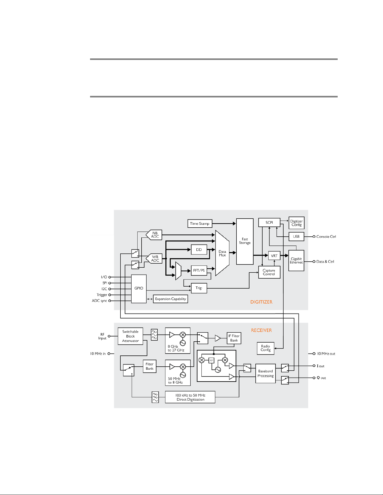
The R5500 Real Time Spectrum Analyzer (RTSA) is a high-performance softwaredefined RF receiver, digitizer and analyzer, as illustrated in Figure 1. With patentpending software-defined RF receiver technology, the RTSA provides industry leading
combined sensitivity, tuning range, instantaneous bandwidth (IBW) and scan rate.
Additionally, it provides real-time sophisticated triggering and capture control.
R5500 Functional Overview
The R5500 is designed for stand-alone, remote and/or distributed wireless signal
analysis. It is ideal for monitoring, management and surveillance of transmitters, whether
they are in-building or spread across a geographic area. Applications include, but are not
limited to:
• 5G wireless technology;
• research;
• test and measurement;
• monitoring;
• OEM integration.
The R5500 hardware largely consists of:
• a hybrid super-heterodyne, direct-conversion and direct-digitization RF receiver
front-end (RFE);
• receiver front end inputs and outputs to support clock synchronization, and IF
outputs for high-end digitization;
• a 125 MSample/sec 14-bit wideband (WB) ADC with a dynamic range of greater
than 70 dB;
• a 300 kSample/sec 24-bit narrowband (NB) ADC with a dynamic range in excess of
100dB;
• a Xilinx's Zynq FPGA with built-in dual-core ARM®-based processor, Gigabit
Ethernet interface and custom embedded digital signal processing (DSP) logic;
• 1 GB of DDR3 shared between firmware and real-time caching of digitized data;
• a general purpose input/output (GPIO) port.
ThinkRF R5500 Real Time Spectrum Analyzer Programmer's Guide 12
Page 13

R5500 Functional Overview
Figure 1: R5500 Functional Block Diagram
ThinkRF's products conform with standardized protocols for interoperability. ThinkRF
provides application programming interfaces (APIs) designed for easy integration with
third-party applications. Standard protocols include the Standard Commands for
Programmable Instruments (SCPI) protocol for controlling and obtaining status from the
RTSA and the VITA-49 Radio Transport (VRT) protocol for digitized data and its
associated context information.
In addition, API libraries, written in C/C++, Python, MATLAB and NI LabVIEW, are
provided for quick interfacing, data acquisition and as well as for spectral analysis with
MATLAB® applications. The Python API is built within the PyRF development framework
and is open-source under BSD licensing. PyRF handles the low-level details of real-time
acquisition, signal processing and visualization, and provides feature rich libraries,
example applications and source code, all specific to the requirements of signal analysis.
Usage examples are provided through the available source codes of the Graphical User
Interfaces (GUI) or any applications included in each release package.
Refer to Appendix A for how to connect to a RTSA and Appendix B for the protocol on
how to find any RTSAs available on the local network. The source code provided for the
aforementioned APIs and GUIs/applications would serve as examples.
The R5500 provides system level control and status commands as defined in Table 1.
Table 1: System Level Control/Status Commands
SCPI Command Description
:SYSTem Page 44
:ABORt Aborts the current data capturing process and puts the RTSA system into
a normal manual mode (i.e. sweep, trigger, and streaming will be aborted)
:CAPTure
13 ThinkRF R5500 Real Time Spectrum Analyzer Programmer's Guide
Page 14

R5500 Functional Overview
SCPI Command Description
:MODE? Gets the current capture mode of the RTSA (i.e. sweeping, streaming or
block mode)
:COMMunicate
:LAN<commands> Subset of commands for configuring/querying RTSA's LAN settings
:ERRor Returns the error code and messages from the SCPI error/event queue
[:NEXT]?
:ALL?
:FLUSh Clears the R5500's internal data storage buffer of any remaining data that
has not transferred out of the RTSA
:LOCK
:HAVE? Returns the current lock state of the task specified
:REQuest? Requests the R5500 to provide a lock on a specific task such that only the
application that has the lock can perform the task
:OPTions? Returns comma separated 3-digit values to represent the hardware
option(s) or features available with a particular RTSA model
:SYNC
:MASTer[?] Sets a RTSA unit to be the master or slave for a synchronization trigger
system with multiple units. Affects :TRIGger:TYPE PULSe or WORD.
:WAIT[?] Sets the delay time in nanoseconds that the system must wait after
receiving the trigger signal before performing data capture
:VERSion? Returns the SCPI version number that the instrument complies with
:DATE[?] Sets/reads date
:TIME[?] Sets/reads time
:ADJust Adjust the system time relative to it's current time
:SYNC[?] Sets/ gets the System time synchronization source via network or SCPI,
or disable
:STATus? Status of the time synchronization
:STATus Page 55
:OPERation Returns the standard Operation Status Register (OSR) for any event
[:EVENt]?
:CONDition?
:ENABle[?]
:PRESET Presets the R5500 (similar to *RST)
:QUEStionable Returns the standard Questionable Status Register (QSR) for any event
[:EVENt]?
:CONDition?
:ENABle[?]
:TEMPerature? Returns the R5500's internal ambient temperature
See SCPI Command Set section (page 40 onward) for further details on the commands.
Caution pertaining to multi-user: The current firmware version of the R5500 allows
multiple applications to connect to the unit simultaneously but it does not support
ThinkRF R5500 Real Time Spectrum Analyzer Programmer's Guide 14
Page 15
R5500 Functional Overview
independent sessions. Therefore, the actions of one user may over-write those of
another. This could potentially damage the unit for instance if the front-end's gain were
incorrectly set. If multiple applications are connecting to the unit, it is advised that only
one of those is controlling the unit at any time.
The Architecture
The R5500 is an integrated wireless radio receiver and digitizer/analyzer. It has an
embedded capture controller that enables users to:
• define and execute real-time and sophisticated triggers, traces and sweeps;
• configure the radio RFE and DSP in association with those traces or sweeps; and
• time-stamping and data output for captures.
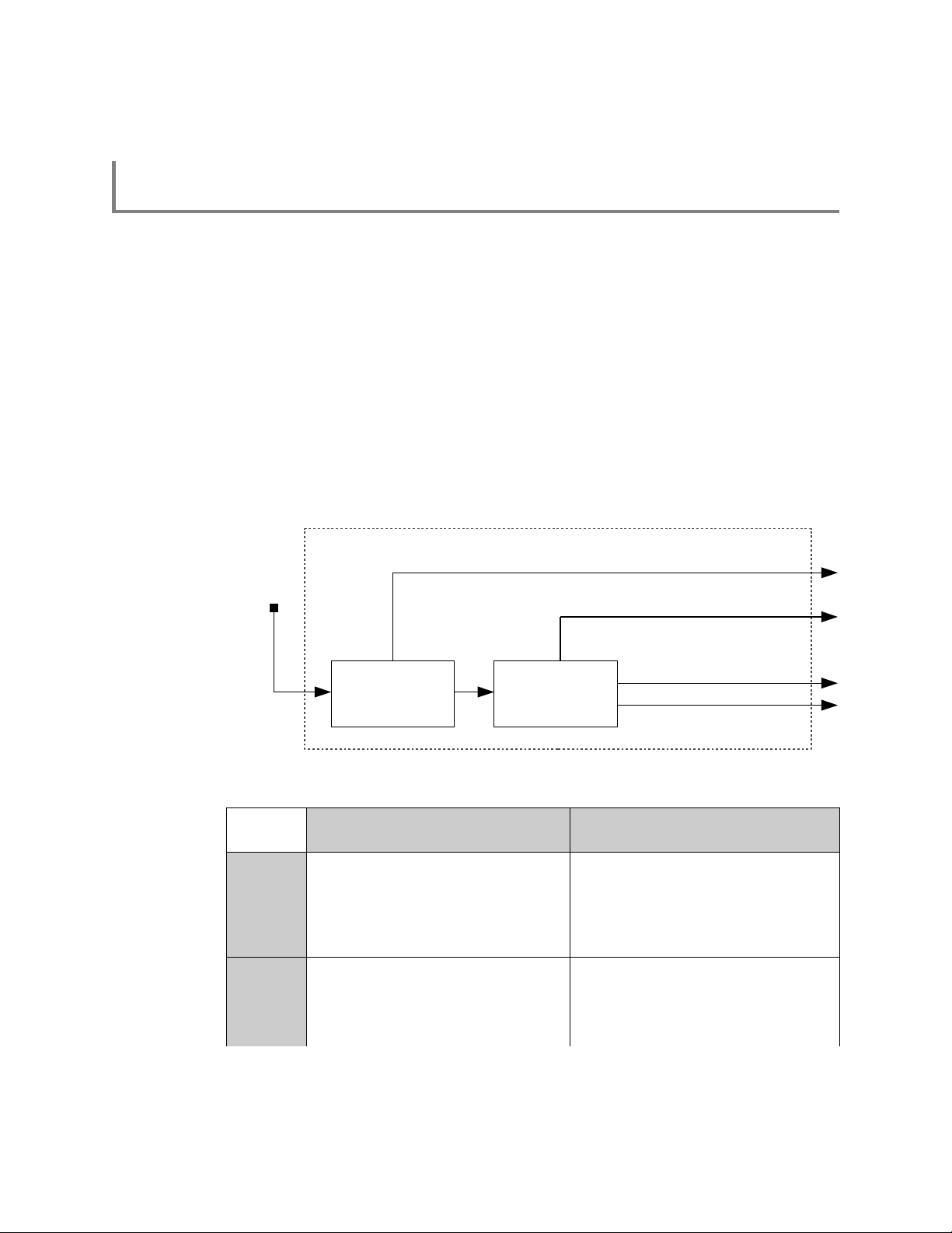
Traces and sweeps are controlled by the capture controller as illustrated in the upper
portion of Figure 2. A trace and a sweep are defined as a single (block or continuously
streamed) capture and a series of captures, respectively, each with their associated
hardware configurations.
Figure 2: RF Receiver Front-end and Capture Controller Functional Block Diagram
The R5500 supports different RFE modes of operation and subsequent DSP capabilities
as per Table 2 and as described in the following subsections.
15 ThinkRF R5500 Real Time Spectrum Analyzer Programmer's Guide
Page 16

R5500 Functional Overview
Table 2: Radio RFE Modes and DSP Data Output Formats
1
Mode
Description Freq Range
(MHz)
ZIF
SH
SHN
HDR
DD
HIF
1
The RFE Mode availability is product dependent.
2
For SH and SHN modes, when the decimation is used, a frequency shift of 35MHz for non-WBIQ
models will be applied automatically to bring the R5500's center frequency back to the zero IF.
Thus, the data output will be I and Q.
3
In DD mode, there is no frequency tuning except for performing frequency shift. When
decimation is applied, the decimation will be around the zero frequency.
Zero-IF Receiver 50 - max 100 I14 Q
Super-Heterodyne
50 - max 40 I
Receiver
SH Receiver with
50 - max 10 I
narrower BW
High Dynamic Range
50 - max 0.1 I
Receiver
Direct Digitization
0.1 - 50
Receiver
High IF Receiver 50 - max -- – – –
3
IBW
(MHz)
50 I
DSP Data Output Format
None CIC/Dec Frequency Shift
14I14 Q14
14
14
24
14
I14 Q
I14 Q
2
14
2
14
- -
I
14
I14 Q
I14 Q
I14 Q
I14 Q
14
14
14
14
R5500 complies to VRT protocol for sending digitized IF data packets and their
associated context information depending on the capture mode. It is very important to
follow the VRT's IF Data Packet Class section (page 34) for the exact VRT data output
formats as well as packing method.
RF Receiver Front-End
The lower portion of Figure 2 shows a block diagram of the RFE within the R5500. The
architecture consists of a super-heterodyne (SH) front-end with a back-end that utilizes
an I/Q mixer similar to that in a direct-conversion (or zero-IF) receiver.
Depending on the frequency of the signals being analyzed, one of the three receiver
signal processing paths is selected. Signals in the frequency range 100kHz to 50MHz
are directly digitized, while all other signals are translated to the frequencies of the first IF
block via one of the other two signal processing paths. The IF block consists of a bank of
multiple SAW filters. SAW filter selection depends on the frequency of the input signal.
The output of the SAW filter feeds the I/Q mixer.
The three signal processing paths are further classified into different modes of operation
for the capture engine as shown in Table 2. The radio modes ZIF, SH, SHN and HDR
support tuning the center frequency from 50MHz to the maximum frequency supported by
the particular product model (ex. 8GHz, 18GHz, and 27GHz for R5500-x08, -x18, and
-x27, respectively, where x is a model number variant).
The ZIF, SH and SHN radio modes support a tuning resolution of 10Hz. Digital
frequency shifting is then used to enhance the tuning resolution to the nearest 1Hz
(±0.23Hz). The frequency shifting technology used is an embedded Numerically
Controlled Oscillator (NCO) (a Direct Digital Synthesizer or DDS) as described in the
Digital Down Converter subsection (page 19).
ThinkRF R5500 Real Time Spectrum Analyzer Programmer's Guide 16
Page 17

R5500 Functional Overview
DC
Offset
Fc-50 MHz
Fc+50 MHz
125 MHz
Fc
Analog filter
The HDR radio mode supports a tuning resolution of 10Hz. No further fine tuning is
available.
The remaining radio mode, DD, support 50MHz IBW direct digitization of the baseband
from the external RF IN. Hence, this mode does not support frequency tuning of the
radio although the DSP's frequency shift mode may be applied.
Direct-Conversion Receiver Technology
Direct-conversion (or ZIF) receivers are ideal for signal analysis of wideband waveforms,
such as 4G/LTE, Wi-Fi and Bluetooth. With that benefit comes the drawback of both IQ
and DC offsets which are inherent to direct-conversion technology.
DC Offset Correction
The R5500's WB ADC sampling rate is 125 MSa/s, intermediate frequency (IF) is 0 and
the entire IF bandwidth is 125MHz. The analog filter results in an amplitude roll-off at
approximately +50MHz around the center frequency Fc, as illustrated in Figure 3.
Direct-conversion receivers have a DC offset at the center of the band. The offset is
primarily compensated for in real-time in the receiver hardware but there always is some
residual offset that (depending on the application and bandwidth of interest) might need
to be compensated for in software. Several options such as calibration or dynamic offset
compensation in software have been described in the open literature.
Figure 3: DC Offset with Amplitude Roll-Off at +50MHz
If the application only needs to utilize up to 50MHz of IBW, a simple alternative to DC
offset compensation is to use the SH mode of operation.
IQ Offset Correction
Direct-conversion receivers have phase and/or amplitude offsets between in-phase (I)
and quadrature (Q) components of the baseband signal. Due to this, when an FFT is
performed on digitized baseband data where there is a signal tone present, there will be
an ‘image’ at the same frequency offset from the center frequency as the tone itself. This
is illustrated in Figure 4.
17 ThinkRF R5500 Real Time Spectrum Analyzer Programmer's Guide
Page 18

R5500 Functional Overview
Signal
Image
XdB
Frequen cy
F
c
Frequen cy
F
c
Fc+Fs
Fc-Fs
calibrateIQ
Figure 4: IQ Offset Correction
A correction algorithm would be needed to adjust this offset necessary for signal analysis,
especially for the ZIF mode. The ThinkRF's APIs have included a correction.
Table 3: RF Front-End Control/Status Commands
SCPI Command Description
:INPut Page 59
:SOURce Page 61
[:SENSe] Page 62
:ATTenuator[?]
:VARiable[?]
Enables/disables the front-end's attenuation (on some models)
Sets the variable attenuation for R5500-418 and -427
:GAIN[?] Sets the input gain stage for a R5500-418, -427 & their variants
:HDR[?]
:MODE[?]
Sets gain level for the NB ADC of of the HDR signal path
Selects the receiver mode of operation
:REFerence
:PLL[?]
:RESET
:DECimation[?] Sets the decimation rate as an exponent of 2 (i.e. rate = 2
Selects the 10MHz reference clock source
Resets the 10MHz reference selection to INTernal source
0, 1, 2 - 10)
level
where level =
:FREQuency
:CENTer[?] Sets the center frequency of the RFE
:IF? Queries the IF frequencies that are used for the current input mode and
center frequency
:INVersion? Queries if a spectral inversion is required at a given frequency
:LOSCillator? Gets the frequency of the external LO 1, 2 or 3 in corresponding to
current the RTSA's center frequency
:SHIFt[?] Sets the frequency shift value (not available for HDR mode)
ThinkRF R5500 Real Time Spectrum Analyzer Programmer's Guide 18
Page 19
R5500 Functional Overview
SCPI Command Description
:LOCK
:REFerence? Queries the lock status of the PLL reference clock
:RF? Queries the lock status of the RFE's PLL
:OUTput Page 66
:MODE[?] Selects the IQ output path to be from the external connector or the
See SCPI Command Set section (page 40 onward) for further details on each set of
commands.
Digital Signal Processing
The R5500 has embedded DSP blocks to provide further signal processing capabilities,
such as DDC with up to 10 levels of decimation and FFT computation.
Digital Down Converter
The DDC block takes the frequency band of interest and shifts it down in frequency, then
provides decimation of the sampling rate to one that is lower and consistent with the
bandwidth of the signal of interest. This enables channelization of signals having
bandwidth smaller than the IBW.
digitizer
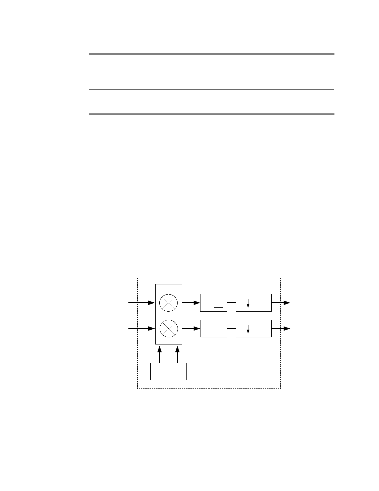
Referring to Figure 5, the DDC has two major elements, an NCO (DDS) and a down
sampling with filtering. The NCO generates a complex sinusoid, which is mixed with the
IQ input using a complex multiplier, to shift or offset the signal spectrum from the selected
carrier frequency. This process provides the frequency fine-tuning (and shifting) feature
as mentioned in the previous subsections.
I
Q
in
in
fs
fsfs
I
Q
out
out
NCO (DDS)
Figure 5: DDC Functional Block Diagram
The complex multiplication is then followed by either a finite impulse response (FIR) filter
or cascaded integrator-comb (CIC) filters with a FIR filter combined. The CIC filter has a
‘droop’ associated with it in the passband. In order to compensate for this droop, the CIC
filter is followed by a compensating FIR filter. Each filter type has its own decimator.
19 ThinkRF R5500 Real Time Spectrum Analyzer Programmer's Guide
Page 20

Triggers
R5500 Functional Overview
This whole process effectively reduces the sample rate and filters the signal to remove
adjacent channels, minimize aliasing, and maximize the received signal-to-noise ratio.
Note: The use of the NCO converts the in-phase signal (I data) input of the receiver's
DD, SH and SHN processing paths to complex I and Q data output. See Table 2.
Triggers provide a means of qualifying the storage of captured time domain IQ data
based on an external, periodic or frequency domain event. Triggering can be considered
a means of filtering signals of interest for the purposes of subsequent visualization
and/or analysis.
The following describes the different types of triggers and their common controls.
Selection of different types is mutually exclusive.
Frequency Domain Triggering
Frequency domain triggering relies on the embedded real-time FFT mechanism to
transform the sampled signal from the time domain to the frequency domain. The R5500
uses a 1024 point real-time FFT core embedded within the FPGA to transform 1024 time
domain IQ samples to 1024 frequency domain FFT bins. Each bin is an average of the
spectral activity over a range of 125MHz divided by the DDC decimation rate divided by
the 1024 FFT points.
The frequency domain triggering supported by R5500 is a level trigger type, used to
capture any signal above the noise floor within a specified frequency range. The user
defines a single amplitude level within a frequency range. The frequency range
encompasses all FFT bins with center frequencies within the range defined by START
and STOP. If the sampled signal amplitude exceeds the defined trigger level at any
single sample within the defined frequency range, the trigger will occur and the
subsequent IQ data capture will proceed.
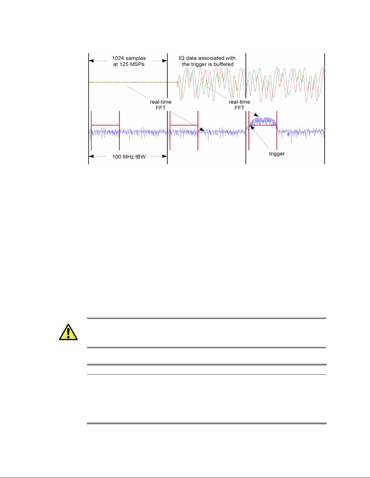
Figure 6 illustrates the association of the time domain and the frequency domain. The
internal frequency domain data lags the time domain data by 1024 samples at the rate of
125 MSa/s. After a trigger event is detected, the subsequent time domain IQ data is then
stored to memory.
ThinkRF R5500 Real Time Spectrum Analyzer Programmer's Guide 20
Page 21
R5500 Functional Overview
The measurable range of the input signal, and the corresponding allowable trigger level
range, varies depending on the selected center frequency, the calibrated reference level
and the attenuation setting. The threshold level error is approximately ±3 dBm or less
when the trigger level is set within the range mentioned in the :TRIGger:LEVel command.
Figure 6: Association between Time and Frequency Domain
See TRIGger Commands (page 67) or SWEep's trigger (page 79) for further details.
Periodic Triggering
Periodic triggering provides a means of capturing a defined amount of IQ data on a
periodic basis. Periodic triggering is typically used for statistical analysis of the captured
signal.
External Triggering
External triggering provides a means of synchronized triggering based on the receiving of
a trigger signal provided via the R5500's GPIO. The trigger “signal” could be a single
pulse, PPS or a sync-word. See Synchronized Sweep (page 24) for additional details.
Caution: The pulse and sync-word is applied to the GPIO's TRIG IN pin, while PPS is
through PPS pin. Contact ThinkRF's Support for details on how to use the GPIO port
prior to connecting anything to the port.
Table 4: Trigger Control/Status Commands
SCPI Command Description
:TRIGger Page 67
:TYPE[?] Sets or disable the trigger type including LEVel | PERiodic | PPS | PULSe
| WORD | NONE
:LEVel[?] Sets the frequency range and amplitude of a frequency domain level
trigger
:PERiodic[?] Sets the time period of a periodic trigger
21 ThinkRF R5500 Real Time Spectrum Analyzer Programmer's Guide
Page 22

See TRIGger Commands (page 67) or SWEep's trigger (page 79) for further details.
Capture Controller
The Capture Controller provides a means of defining and performing simple traces and
complex sweeps. For example, it allows for:
• the definition and execution of a complex sweep;
• the interruption of that sweep;
• the execution of a specific trace; and
• the resumption of the previous sweep.
Caution: The configurations of the capture engine associated with :TRACe and :SWEep
commands are fully independent of each other. A :TRACe command uses the
configurations of the capture engine based on the root :INPut, :SENSe and :TRIGger
commands. It does not use the configurations based on the :SWEep command subset.
Trace Capture Control
The :TRACe capture control initiates the capture, storage and conditionally the sending of
IQ data through triggering when used. It supports both streaming and block mode
capture.
R5500 Functional Overview
The :TRACe:BLOCk (page 69) command initiates a block capture of continuous IQ data
(available to be "pulled" from the R5500 per command issued). Once it is issued, data
will be stored instantly (conditional on triggering), contiguously and reliably and are
available to be read. The maximum size of a block is limited by the memory device in the
RTSA.
The :TRACe:STReam (page 71) command initiates the streaming of IQ data (which is
"pushed" from the R5500). Once it is issued, data packets will be sent instantly
(conditional on triggering) and continuously on best effort basis (in other words, data
might not be continuous from one packet to the next once the internal buffer is full).
The execution of the trace capture could be conditioned by the triggering. The triggering
may be enabled or disabled via the :TRIGger:TYPE command, thereby, supporting freerun or triggered signal searches.
Table 5: Trace Capture Control Commands
SCPI Command Description
:TRACe Page 68
:BLOCk
:DATA? Initiates the sending of the IQ data captured
:PACKets[?] Sets the number of IQ data packets to be captured per block (a block =
:PACKets * SPP)
:SPPacket[?] Defines the number of samples per VRT packet
:STReam
:STARt Initiates the capture, storage and streaming of IQ data
ThinkRF R5500 Real Time Spectrum Analyzer Programmer's Guide 22
Page 23

R5500 Functional Overview
SCPI Command Description
:STOP Stops streaming
See TRACe Commands section (page 68) for further details.
Sweep Capture Control
The :SWEep capture control provides the ability to define and execute simple or complex
sweeps. A sweep setup consists of defining a list or multiple lists and executing one of
the defined lists, with each list consisting of one or more entries storing different capture
engine configurations. A list may be edited, deleted and/or executed using the
:SWEep:LIST command set.
The :SWEep:ENTRy commands provide the ability to define the capture engine
configurations equivalent to most of :INPut, :SENSe, :TRACe and :TRIGger commands
for each sweep entry. Sweep entries are identified by an index number and may be
inserted, edited and/or deleted like rows in a table or spreadsheet.
There are slight differences between the configuration options for trace versus sweep
captures. The sweep allows for definition of a range of center frequencies whereby the
center frequency is incremented in frequency by a step value. Level triggers may be
defined over the entire range of center frequencies. Sweeping does not support time
delayed triggers.
In addition, sweep mode data packets, whether VRT context or digitized data, are
“streamed” or “pushed” from the RTSA (similar to :TRACe:STReam).
Table 6: Sweep Capture Control/Status Interface
SCPI Command Description
:SWEep Page 72
:LIST
:ITERations[?] Defines the number of times the list is repeated during execution
:STARt Begins execution of the current sweep list from the first entry
:STATus? Get the current sweep status
:STOP Stops execution of the current sweep list
:ENTRy All entry commands operate on the current list
:COPY Copies the settings of an existing sweep entry into the current settings for
quick editing
:COUNt? Gets the number of entries available in the list
:DELETE Deletes the specified entry or all entries
:NEW Sets the sweep entry settings to default values
:READ? Gets the settings of an existing sweep entry
:SAVE Saves the current editing entry to the end of the list or before the specified
ID location in the list when the integer value is given
:ATTenuator As defined in :INPut:ATTenuator, page 59
:VAR[?] As defined in :INPut:ATTenuator:VARiable, page 59
:DECimation[?] As defined in [:SENSe]:DECimation, page 62
23 ThinkRF R5500 Real Time Spectrum Analyzer Programmer's Guide
Page 24

R5500 Functional Overview
SCPI Command Description
:FREQuency
:CENTer[?] Defines the center frequency of the RFE or a range of frequencies that
are stepped by the value defined by the :FREQuency:STEP
:STEP[?] Defines the amount of frequency that the center frequency is stepped by
:SHIFt[?] As defined in [:SENSe]:FREQuency:SHIFt, page 65
:GAIN
:HDR[?] As defined in :INPut:GAIN:HDR, page 60
:MODE As defined in :INPut:MODE, page 61
:DWELl[?] Sets the maximum amount of time waited for a trigger to occur after which
the trigger is aborted
:PPBlock[?] Same as :TRACe:BLOCk:PACKets, page 70
:SPPacket[?] As defined in :TRACe:SPPacket, page 70
:TRIGger
:TYPE[?] As defined in :TRIGger:TYPE, page 67
:LEVel[?] As defined in :TRIGger:LEVel, page 67
:PERiodic[?] As defined in :TRIGger:PERiodic, page 68
See SWEep Commands section (page 72) for further details.
Synchronized Sweep
The R5500 supports a synchronized sweep function for the purposes of comparing the
same signal received via multiple R5500s.
Synchronized sweep is an extension of the external trigger capability. One of the R5500s
in a network is configured to be the master (:SYSTem:SYNC:MASTer ON) and the other
R5500s are configured as slaves (:SYSTem:SYNC:MASTer OFF). The master and
slaves are configured with a sweep list, in which each sweep entry has a synchronization
trigger type (:SWEep:ENTRy:TRIGger:TYPE PULSE | WORD). The synchronization
trigger is generated and delivered from the master's GPIO to that of the slaves to indicate
the beginning of a capture.
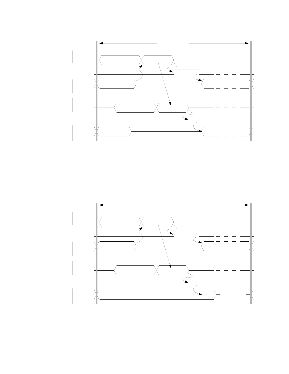
Figure 7 provides a synchronization trigger example using sync-word. The master sends
the sync-word when the setup of its front-end has been completed. Master and slaves
are also individually configured with a delay variable (:SYSTem:SYNC:WAIT <nsec> with
a resolution of 8 nsec). This delay wait time accounts for the typical worst-case front-end
setup time and for differences in the synchronization cable length. Master and slaves
then begin the capture upon the expiration of the wait (or delay).
ThinkRF R5500 Real Time Spectrum Analyzer Programmer's Guide 24
Page 25
R5500 Functional Overview
front end setup
capture...........
syncpreamble
front end setup capture...........
sweep step
MASTER
sent
syncword
received
syncword
delay
delay
setup
and
capture
setup
and
capture
SLAVE
syncpreamble
syncpreamble
front end setup
front end setup
capture...........
missed capture
sweep step
MASTER
sent
syncword
received
syncword
delay
delay
setup
and
capture
setup
and
capture
SLAVE
syncpreamble
The front-end setup time is typically of approximately 200 usec but is variable due to the
embedded running processes. Referring to Figure 8, if the front-end setup time on one
(or more) of the slaves is longer than the combined duration of the master's setup time
plus the sync-word plus the slave's delay, then the slave will miss the beginning of the
capture. The host-side application that is collating the capture data may recognize the
missed capture by noting the timestamps and/or frequency of the capture data within the
associated VRT Receiver Context packets. The rate of sweep versus the amount of
missed captures may be balanced by adjusting the delay values.
Figure 7: Synchronized Sweep using Sync-Word
Figure 8: Synchronized Sweep with a Missed Capture
See SWEep Commands section (page 72) for further interface details or contact
ThinkRF's Support for more information.
25 ThinkRF R5500 Real Time Spectrum Analyzer Programmer's Guide
Page 26
VITA-49 Radio Transport Protocol
VITA-49 Radio Transport Protocol
The section describes the R5500's VRT Information Class as per the "VITA Radio
Transport (VRT) Draft Standard" Specification VITA-49.0 – 2007 Draft 0.21.
Purpose
Convey an arbitrary 100MHz of IF data and associated information from the R5500 to
another equipment using an industrial standard.
R5500's VRT Overview
ThinkRF's VRT supports four different packet streams of information defined and
organized as shown in Figure 9 and Table 7. The streams of packets are sent when the
data capture is started. The context packets carry the R5500 settings information
associated with the immediate following IF data packets.
Receiver Context Stream
Reference Point
Digitizer Context Stream
Extension Context Stream
RECEIVER DIGITIZER
IF Data Stream
Figure 9: Connectivity and 4 Different Packet Streams Supported by R5500
Table 7: The Categories of VRT Packet Streams Supported by ThinkRF's R5500
Standard Formats Custom Formats
Contents
Context
Data
IF Context Packet Stream
conveys metadata concerning IF Data
Packet Stream and the settings
- Digitizer Context Packet Class Stream
- Receiver Context Packet Class Stream
IF Data Packet Stream
conveys discrete time sampled signal
data
Extension Context Packet Stream
conveys additional Context concerning IF
or Extension Data Packet Stream
- Extension Context Packet Class Stream
Extension Data Packet Stream
conveys any signal or data derived from a
signal
- IF Data Packet Class Stream
- Currently not used
26 ThinkRF R5500 Real Time Spectrum Analyzer Programmer's Guide
Page 27

VITA-49 Radio Transport Protocol
Receiver Context Packet Class Stream
The Receiver Context Packet Class Stream is used to convey informational messages
about changes in the configuration and status of the RF receiver in the R5500.
Digitizer Context Packet Class Stream
The Digitizer Context Class Stream is used to convey information messages about
changes in the configuration and status of the IF digitizer in the R5500.
Extension Context Packet Class Stream
The Extension Context Packet Class Stream is used to convey metadata for the IF Data
Packet Stream, which no provision has been made in the IF Context Packet Stream.
IF Data Packet Class Stream
The IF Data Packet Stream is used to convey complex IQ samples from the digitizer to
devices external to the R5500.
Table 8 summarizes numerically the list of Stream Identifiers used by ThinkRF for
different Packet Class Stream. Each ID will be mentioned in the subsequent
corresponding Packet Class sections.
Table 8: A List of Stream Identifiers As Used by ThinkRF for Different Packet Classes
Stream Identifier Packet Class
0x90000001 Receiver Context
0x90000002 Digitizer Context
0x90000003 IF Data – {I14Q14} Format
0x90000004 Extension Context
0x90000005 IF Data – {I14} Format
0x90000006 IF Data – {I24} Format
Packet Classes and Streams
This section describes in details the rules and structure of those Packet Classes and
Streams. By definition, a series of packets instantiated from the same Packet Class
form a Packet Stream.
Note: All data words in each VRT packets are in big-endian order, and sent MSB first.
Receiver Context Packet Class
This Packet Class is a type of IF Context Packet Class. The packet information conveys
changes in the configuration and status of the R5500's RF receiver.
ThinkRF R5500 Real Time Spectrum Analyzer Programmer's Guide 27
Page 28

VITA-49 Radio Transport Protocol
Table 9: Receiver Context Packet Class Structure
31 30 29 28 27 26 25 24 23 22 21 20 19 18 17 16 15 14 13 12 11 10 9 8 7 6 5 4 3 2 1 0
Pkt Type
0 1 0 0
C R T
1. Pkt Type shall be set to 0100 to indicate this is a context packet.
2. C shall be set to 0 to indicate there is no Class Identifier in the packet.
3. R shall be set to 00, because they are reserved bits.
4. TSM (TimeStamp Mode) shall be set to 0, indicating that context packet
timestamps are precise.
5. TSI (TimeStamp-Integer) field shall be set to 01, indicating that integer (seconds)
part of the timestamps are in Coordinated Universal Time (UTC).
6. TSF (TimeStamp-Fractional) field shall be set to 10, indicating that the fractional
part of the timestamp measures in real time picosecond resolution.
7. Pkt Count shall start at 0000 and increment once for each context packet, until
reaching 1111 (or 15), where it shall rollover to 0000 on the next count.
8. Pkt Size indicates the total number of 32-bit words in the entire context packet,
including all headers, the context indicator field and context sections.
9. Stream Identifier shall be the 32-bit word, 0x90000001
10. Timestamp - Integer Seconds shall be in UTC format and will represent the
number of seconds occurred since Midnight, January 1, 1970, GMT.
11. Timestamp - Integer Picoseconds shall count the number of picoseconds past
since the last increment of the Timestamp seconds field. See the Picosecond
Timestamp Words Format section for the format.
12. The Context Indicator Field shall follow the format indicated in Table 10.
TSI TSF Pkt Count Pkt Size
S
M
Stream Identifier (1 word)
Timestamp - Integer Seconds (1 word)
Timestamp - Integer Picoseconds (2 words)
Context Indicator Field (1 word)
Context Fields (Variable Size)
Table 10: Receiver Context Indicator Field Positions
31 30 29 28 27 26 25 24 23 22 21 20 19 18 17 16 15 14 13 12 11 10 9 8 7 6 5 4 3 2 1 0
I R - F - G - T -
13. The Context Fields section shall contain a context field for every field that is
indicated to be present in the Context Indicator Field. The fields shall be ordered
in the identical order of their occurrence in the Context Indicator Field. See Table
11 for the definition and associated value of each field.
Table 11: Receiver Context Field Definition and Values
Bit Name Context Field # of Words in Field Period of Validity
I Context Field Change Indicator 0 N/A
R Reference Point 1 Persistent
F RF Reference Frequency 2 Persistent
G Gain 1 Persistent
T Temperature 1 Persistent
28 ThinkRF R5500 Real Time Spectrum Analyzer Programmer's Guide
Page 29

VITA-49 Radio Transport Protocol
Context Field Change Indicator
The Context Field Change Indicator is used to indicate when some context value of the
system has changed. One or more of the other bits in the indicator field will be also set,
indicating which values have been changed and have their updated values in the context
fields that follow. It is possible that a context packet may be sent where the Context Field
Change Indicator is set to 0, indicating that no change has occurred.
RF Reference Frequency
The RF Reference Frequency communicates the frequency of origin for the signal. The
value of the RF Reference Frequency shall be expressed in units of Hertz. The RF
Reference Frequency sub-field shall use the 64-bit, two’s-complement format as shown
in Table 12. This field has an integer and a fractional part, with the radix point to the right
of bit 20 in the second 32-bit word. This gives the RF Reference Frequency a range of
±8.79THz with a resolution of 0.95μHz.
Table 12: RF Reference Frequency Word Format
31 30 29 28 27 26 25 24 23 22 21 20 19 18 17 16 15 14 13 12 11 10 9 8 7 6 5 4 3 2 1 0
Integer RF Reference Value (43..12), Hz
Integer RF Ref. Value (11..0), Hz Fractional RF Reference Value(19..0)
Gain
The gain is a 32-bit value that is split into two 16-bit values, representing the Stage 1 and
Stage 2 gain values. The Stage 1 gain represents the amount of gain in the front-end
system, the RF gain. The Stage 2 gain represents the amount of gain in the back-end
system, the IF gain.
Each gain value is a signed two's-complement number, having two sub-fields, bits 15:7
being the integer value, and 6:0 being the fractional value. This gives each gain figure a
range of ±256dB with a resolution of 1/128dB (0.0078125dB).
Table 13: Gain Field Format
31 30 29 28 27 26 25 24 23 22 21 20 19 18 17 16 15 14 13 12 11 10 9 8 7 6 5 4 3 2 1 0
Integer IF Fractional IF Integer RF Fractional RF
Temperature
This field is not yet available.
The R5500 has a temperature sensor and will report changes in temperature to the
system. The value of the Temperature field shall be expressed in units of degrees
Celsius (°C). The Temperature field shall use the 32-bit format shown in Table 14 with
the upper 16 bits reserved and shall be set to zero. The Temperature value shall be
expressed in signed two’s-complement format in the lower 16 bits of this field. This field
has an integer and a fractional part, with the radix point to the right of bit 6.
Table 14: Temperature Field Format
31 30 29 28 27 26 25 24 23 22 21 20 19 18 17 16 15 14 13 12 11 10 9 8 7 6 5 4 3 2 1 0
Reserved Integer Temperature Fractional Temp.
ThinkRF R5500 Real Time Spectrum Analyzer Programmer's Guide 29
Page 30

VITA-49 Radio Transport Protocol
The valid range of the Temperature field is -273.15 °C to +511.984375 °C. The resolution
of the Temperature field is 0.015625 °C (1/64 °C).
For examples, a Temperature field value of:
• 0x0040 represents +1 °C,
• 0xFFC0 represents -1 °C,
• 0x0001 represents +0.015625 °C, and
• 0xFFFF represents -0.015625 °C.
Digitizer Context Packet Class
This Packet Class is a type of IF Context Packet Class. The packet information conveys
changes in the configuration and status of the R5500's IF digitizer.
Table 15: Digitizer Context Packet Class Structure
31 30 29 28 27 26 25 24 23 22 21 20 19 18 17 16 15 14 13 12 11 10 9 8 7 6 5 4 3 2 1 0
Pkt Type
0 1 0 0
C R T
TSI TSF Pkt Count Pkt Size
S
M
Stream Identifier (1 word)
Timestamp - Integer Seconds (1 word)
Timestamp - Integer Picoseconds (2 words)
Context Indicator Field (1 word)
Context Section (Variable Size)
1. Pkt Type shall be set to 0100 to indicate this is a context packet.
2. C shall be set to 0 to indicate there is no Class Identifier in the packet.
3. R shall be set to 00, because they are reserved bits.
4. TSM shall be set to 0, indicating that context packet timestamps are precise.
5. TSI field shall be set to 01, indicating that integer (seconds) part of the timestamps
are in UTC.
6. TSF field shall be set to 10, indicating that the fractional part of the timestamp
measures real time picosecond resolution.
7. Pkt Count shall start at 0000 and increment once for each context packet, until
reaching 1111 (or 15), where it shall rollover to 0000 on the next count.
8. Pkt Size indicates the size of the entire context packet, including all headers, the
context indicator field and context sections.
9. Stream Identifier shall be the 32-bit word, 0x90000002.
10. Timestamp - Integer Seconds shall be in UTC format and will represent the
number of seconds occurred since Midnight, January 1, 1970 GMT.
11. Timestamp - Integer Picoseconds shall count the number of picoseconds past
since the last increment of the Timestamp seconds field. See the Picosecond
Timestamp Words Format section for the format.
12. The Context Indicator Field shall follow the format indicated in Table 16.
Table 16: Digitizer Context Indicator Field Bit Positions
31 30 29 28 27 26 25 24 23 22 21 20 19 18 17 16 15 14 13 12 11 10 9 8 7 6 5 4 3 2 1 0
I B O R
30 ThinkRF R5500 Real Time Spectrum Analyzer Programmer's Guide
Page 31

13. The Digitizer Context Fields section shall contain a context field for every field
P=R+20∗log( IQ
measured
)
IQ
measured
=√(I
fft
2
+Q
fft
2
)
that is indicated to be present in the Context Indicator Field. The fields shall be
ordered in the identical order of their occurrence in the Context Indicator Field.
See Table 17 for the definition and associated value of each field.
Table 17: Digitizer Context Field Values
Bit Name Context Field # of Words in Field Period of Validity
I Context Field Change Indicator 0 N/A
B Bandwidth 2 Persistent
O RF Frequency Offset 2 Persistent
R Reference Level 1 Persistent
Context Field Change Indicator
The Context Field Change Indicator is used to indicate when some context value of the
system has changed. One or more of the other bits in the indicator field will be also set,
indicating which values have been changed and have their updated values in the context
fields that follow. It is possible that a context packet may be sent where the Context Field
Change Indicator is set to 0, indicating that no change has occurred.
Bandwidth
VITA-49 Radio Transport Protocol
The bandwidth is used to indicate that the amount of spectrum that is currently view-able
due to decimation settings that have been enabled.
The Bandwidth field shall use the 64-bit, two’s-complement format as shown in Table 18.
This field has an integer and a fractional part, with the radix point to the right of bit 20 in
the second 32-bit word. This gives the RF Reference Frequency a range of ±8.79THz
with a resolution of 0.95μHz.
Table 18: Bandwidth Word Format
31 30 29 28 27 26 25 24 23 22 21 20 19 18 17 16 15 14 13 12 11 10 9 8 7 6 5 4 3 2 1 0
Integer Bandwidth (11..0), Hz Fractional Bandwidth (19..0)
Reference Level
The Reference Level indicator provides a power level reference so that the magnitude of
the received data can be calculated by a user. The reference level provided in the context
packet is adjusted according to the RFE's gain setting. However, the reference levels
must also be adjusted accordingly relative to the antenna (the Reference Point) and to
any other conditions.
The absolute power level P (in dBm) is then computed using the following formula:
Integer Bandwidth (43..12), Hz
ThinkRF R5500 Real Time Spectrum Analyzer Programmer's Guide 31
with
Page 32

VITA-49 Radio Transport Protocol
where:
R = the reference level provided in the VRT context packet, dBm
IQ
= as shown in the formula above. The IQ
measured
simplified example as it doesn't include any corrections, such as IQ imbalance,
DC offset or windowing
I
= the real component of the FFT (Fast Fourier Transform) computation applied
fft
on the VRT I data, which is normalized by dividing each Q by 2
Q
= the imaginary component of the FFT computation applied on the VRT Q
fft
data (when used), which is normalized by dividing each Q by 2
The Reference Level field shall use the 32-bit format shown in Table 19 with the upper 16
bits reserved and shall be set to zero. The Reference Level field value shall be
expressed in signed two’s-complement format in the lower 16 bits of this field. This field
has an integer and a fractional part, with the radix point to the right of bit 7.
Table 19: Reference Level Field Format
31 30 29 28 27 26 25 24 23 22 21 20 19 18 17 16 15 14 13 12 11 10 9 8 7 6 5 4 3 2 1 0
Reserved Integer Ref. Level Frac. Ref. Level
The value of the Reference Level field has a range of nearly ±256dBm with a resolution
of 1/128dBm (0.0078125dBm).
For examples, a Reference Level field value of:
• 0x0080 represents a reference level of +1dBm,
• 0xFF80 represents -1dBm,
• 0x0001 represents +0.0078125dBm, and
• 0xFFFF represents -0.0078125dBm.
formula, however, is a
measured
bit_size – 1
bit_size – 1
RF Frequency Offset
The RF Frequency Offset indicator specifies the amount of frequency in Hz the received
data has been shifted.
The RF Frequency Offset field shall use the 64-bit, two’s-complement format as shown in
Table 20. This field has an integer and a fractional part, with the radix point to the right of
bit 20 in the second 32-bit word. This gives the RF Reference Frequency a range of
±8.79THz with a resolution of 0.95μHz.
Table 20: RF Frequency Offset Word Format
31 30 29 28 27 26 25 24 23 22 21 20 19 18 17 16 15 14 13 12 11 10 9 8 7 6 5 4 3 2 1 0
Integer RF Reference Value (43..12), Hz
Integer RF Ref. Value (11..0), Hz Fractional RF Reference Value(19..0)
Extension Context Packet Class
This Packet Class conveys metadata concerning IF Data Packet Class that cannot be
communicated in the IF Context Packet Class. See Table 21 for the organization of this
context packet class.
32 ThinkRF R5500 Real Time Spectrum Analyzer Programmer's Guide
Page 33
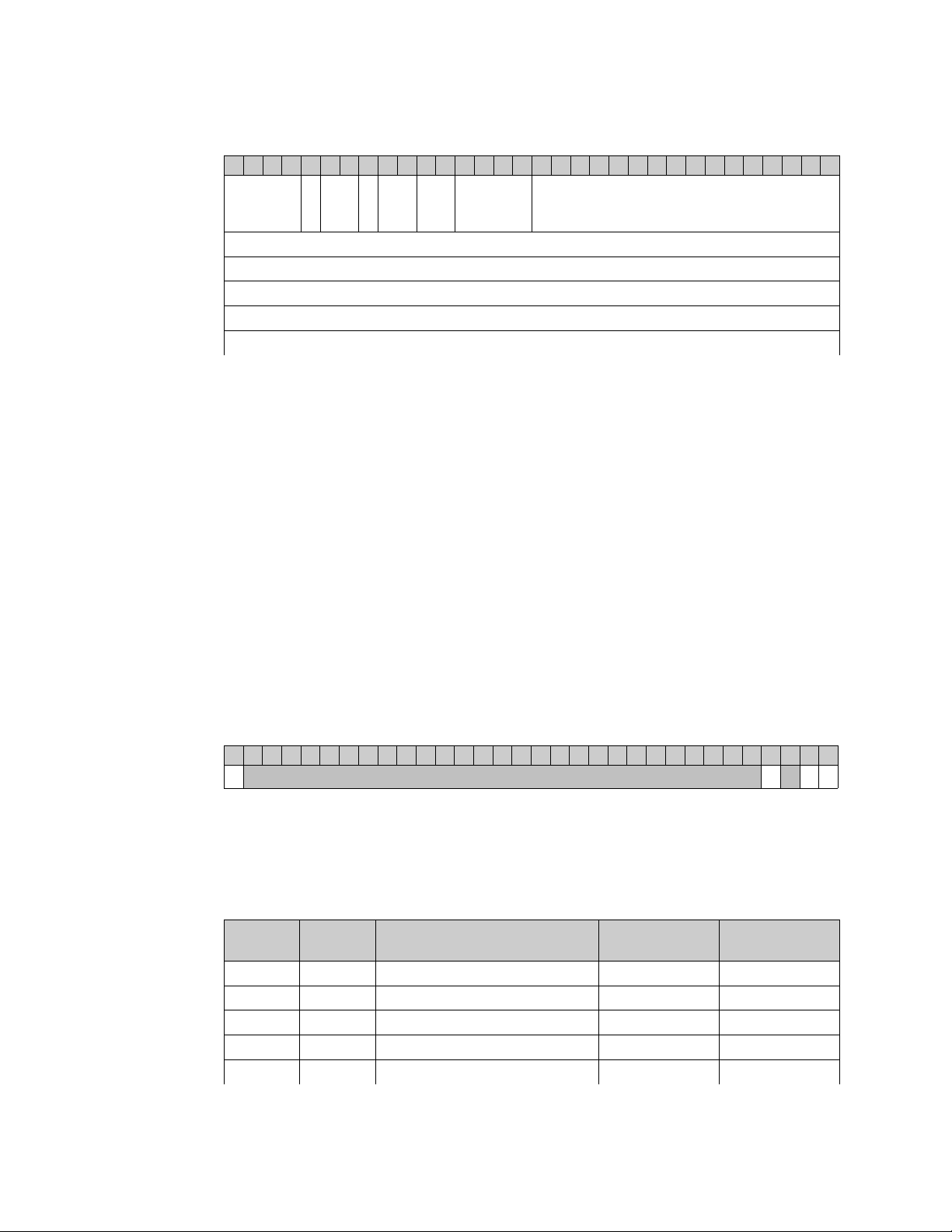
VITA-49 Radio Transport Protocol
Table 21: Extension Context Packet Class Structure
31 30 29 28 27 26 25 24 23 22 21 20 19 18 17 16 15 14 13 12 11 10 9 8 7 6 5 4 3 2 1 0
Pkt Type
0 1 0 1
C R T
TSI TSF Pkt Count Pkt Size
S
M
Stream Identifier (1 word)
Timestamp - Integer Seconds (1 word)
Timestamp - Integer Picoseconds (2 words)
Context Indicator Field (1 word)
Context Fields (Variable Size)
1. Pkt Type shall be set to 0101 to indicate this is an extension packet.
2. C shall be set to 0 to indicate there is no Class Identifier in the packet.
3. R shall be set to 00, because they are reserved bits.
4. TSM shall be set to 0, indicating that context packet timestamps are precise.
5. TSI field shall be set to 01, indicating that integer (seconds) part of the timestamps
are in UTC.
6. TSF field shall be set to 10, indicating that the fractional part of the timestamp
measures in real time picosecond resolution.
7. Pkt Count shall start at 0000 and increment once for each context packet, until
reaching 1111, where it shall rollover to 0000 on the next count.
8. Pkt Size indicates the total number of 32-bit words in the entire context packet,
including all headers, the context indicator field and context sections.
9. Stream Identifier shall be the 32-bit word, 0x90000004
10. Timestamp - Integer Seconds shall be in UTC format and will represent the
number of seconds occurred since Midnight, January 1, 1970, GMT.
11. Timestamp - Integer Picoseconds shall count the number of picoseconds past
since the last increment of the Timestamp seconds field. See the Picosecond
Timestamp Words Format section for the format.
12. The Context Indicator Field shall follow the format indicated in Table 22.
Table 22: Extension Context Indicator Field Positions
31 30 29 28 27 26 25 24 23 22 21 20 19 18 17 16 15 14 13 12 11 10 9 8 7 6 5 4 3 2 1 0
I IQ Sc St Sw
13. The Context Fields section shall contain a context field for every field that is
indicated to be present in the Context Indicator Field. The fields shall be ordered in
the identical order of their occurrence in the Context Indicator Field. See Table 23
for the definition and associated value of each field.
Table 23: Receiver Context Field Definition and Values
Bit Name Bit
Position
I 31 Context Field Change Indicator 0 N/A
IQ 3 IQ Swapped Indicator 0 Persistent
Sc 2 N/A N/A N/A
St 1 New Stream Start ID 1 Persistent
Sw 0 New Sweep Start ID 1 Persistent
Context Field # of Words in
Field
Period of
Validity
ThinkRF R5500 Real Time Spectrum Analyzer Programmer's Guide 33
Page 34

VITA-49 Radio Transport Protocol
Context Field Change Indicator
The Context Field Change Indicator is used to indicate when some context value of the
system has changed. One or more of the bits in the indicator field will then be set,
indicating which values have been changed and have their updated values in the context
field(s) that follow. It is possible that a context packet may be sent where the Context
Field Change Indicator is set to 0, indicating that no change has occurred.
IQ Swapped Indicator
The IQ Swapped Indicator is used to indicate whether the two ADC data channels has
been swapped due to the mixing of a high-side or low-side LO injection at a given center
frequency. When the value is 1, the channels are swapped and 0 if not. This swapping
is necessary to maintain the data output format to always be {I,Q} such that the spectral
inversion is not required at the user-end during data processing.
This information, however, matters only when operating in the ZIF mode. The ZIF mode
is a direct conversion receiver architecture that typically creates some artifacts, mainly
due to IQ gain and phase imbalances. The artifacts are compensated by using a specific
correction algorithm, which incorporates both time- and frequency-domain corrections.
Further information on the algorithm and its usage will be provided in a future release.
Contact ThinkRF's Support for more information if necessary.
New Stream Start ID
The New Stream Start ID indicator indicates a new stream capture has started, any
packets following this Context Packet belong to this new stream capture.
The value of the New Stream Start ID field shall use the 32-bit unsigned integer format
shown in Table 24.
Table 24: New Stream Start ID Field Format
31 30 29 28 27 26 25 24 23 22 21 20 19 18 17 16 15 14 13 12 11 10 9 8 7 6 5 4 3 2 1 0
New Stream Start ID
New Sweep Start ID
The New Sweep Start ID indicator indicates a new sweep has started, any packets
following this Context Packet belong to this new sweep.
The value of the New Sweep Start ID field shall use the 32-bit unsigned integer format
shown in Table 25.
Table 25: New Sweep Start ID Field Format
31 30 29 28 27 26 25 24 23 22 21 20 19 18 17 16 15 14 13 12 11 10 9 8 7 6 5 4 3 2 1 0
New Sweep Start ID
IF Data Packet Class
The IF Data Packet Class conveys digitized IF Data from the digitizer to devices external
to the R5500. The payload data and its output format is dependent on the RFE modes of
operation (:INPut:MODE or :SWEep:ENTRy:MODE). In addition to Table 2 (page 16),
34 ThinkRF R5500 Real Time Spectrum Analyzer Programmer's Guide
Page 35

VITA-49 Radio Transport Protocol
the following Table 26 describes the output data width and packing method for the
different data type in order comply with VRT's 32-bit word output format:
Table 26: Output Data Width and Packing Method for Different Data Formats
Original Data
Format
{I14Q14}
{I14}
{I24}
Binary Format Per
Data Component
Signed 2-complement
Signed 2-complement
Signed 2-complement
Signed
Extension
{I16Q16} {I16Q16}
{I16} {I116I216}
{I32} {I32}
Per 32-bit Word
Packing Method
The different Stream Identifier values will be used to indicate these different formats.
The order of the fields in an IF Data packet is organized as shown in Table 27. Packets
is transmitted in big-endian byte order.
Table 27: IF Data Class Field Values
31 30 29 28 27 26 25 24 23 22 21 20 19 18 17 16 15 14 13 12 11 10 9 8 7 6 5 4 3 2 1 0
Pkt Type C T - TSI TSF Pkt Count Pkt Size
Stream Identifier (1 word)
Timestamp - Integer Seconds (1 word)
Timestamp - Integer Picoseconds (2 words)
Data Payload (Variable Size)
Trailer (1 word)
1. Pkt Type shall be 0001, indicating that a stream identifier is present.
2. C shall be set to 0, indicating that there is no class identifier present.
3. T shall be set to 1, indicating there is a trailer word in the packet.
4. TSI field shall be set to 01, indicating that integer (seconds) part of the timestamps
are in UTC.
5. TSF field shall be set to 10, indicating that the fractional part of the timestamp
measures in real time picosecond resolution.
6. Pkt Count shall start at 0000, and be incremented once for each IF Data packet
that is received, until reaching 1111, when it then wraps back to 0000 on the next
count.
7. Pkt Size shall be the number of 32-bit words that are present in the packet,
including all headers, data payload and trailer if included.
8. Stream Identifier shall have the values as shown in the following Table 28.
Table 28: Stream Identifier Values for Different Data Output Formats
Data Output Format Stream Identifier
{I14Q14} 0x90000003
{I14} 0x90000005
{I24} 0x90000006
9. Timestamp - Integer Seconds shall be in UTC format and will represent the
number of seconds occurred since Midnight, January 1st, 1970, GMT.
ThinkRF R5500 Real Time Spectrum Analyzer Programmer's Guide 35
Page 36

VITA-49 Radio Transport Protocol
10. Timestamp - Integer Picoseconds shall count the number of picoseconds past
since the last increment of the Timestamp seconds field. See Table 29.
11. Data Payload shall contain the IF data from the R5500, arranged in the format
indicated in Table 30 to Table 32.
12. Trailer shall be included and be arranged in the format described in Table 33.
Picosecond Timestamp Words Format
The two 32-bit words timestamp allotted for picoseconds are arranged as below.
Table 29: 64-bit or Two Words Picosecond Timestamp Format
31 30 29 28 27 26 25 24 23 22 21 20 19 18 17 16 15 14 13 12 11 10 9 8 7 6 5 4 3 2 1 0
Data Payload Format
The data payload of an IF Data packet contains a contiguous sequence of the Data
Samples from an IF Data Sample stream. The number of words in the data payload is
variable from packet to packet, and can be determined at the receiving end of the link
from the Packet Size by subtracting the number of words dedicated to the header, trailer,
and other additional fields. The presence or absence of these fields can be determined
entirely from information in the header.
Timestamp – picoseconds, Word 1 (63..32)
Timestamp – picoseconds, Word 2 (31..0)
1. The maximum number of data payload 32-bit words shall be 216-16 and must be a
multiple of 16. Limitation due to embedded data transferring engine.
2. The data payload shall consist of an integer number of contiguous 32-bit words.
3. IF Data Packets convey either the time domain in-phase (I or real) and/or
quadrature (Q or imaginary) components forming the Complex Cartesian samples.
{I14Q14} Data Payload Format
4. Each I or Q data is a signed two's-complement 14-bit data with signed extended
into 16-bit. Thus, each component is an integer ranging from -8192 to +8191 (or
±213).
5. The I-component is in the upper 16-bit of each data word followed by the Qcomponent in the lower 16-bit, as seen in Table 30.
Table 30: {I14Q14} Data Payload Arrangement with Upper 2-bit of Each Item Signed Extended to
{I
}
16 Q16
31 30 29 28 27 26 25 24 23 22 21 20 19 18 17 16 15 14 13 12 11 10 9 8 7 6 5 4 3 2 1 0
0bxx
0bxx
0bxx
.
.
.
Item 1 (Sample 1 I14)
Item 3 (Sample 2 I14)
Item 5 (Sample 3 I14)
.
.
.
0bxx
0bxx
0bxx
.
.
.
Item 2 (Sample 1 Q14)
Item 4 (Sample 2 Q14)
Item 6 (Sample 3 Q14)
.
.
.
Example conversion, given the big-endian bytes 0x0018FFFE received:
• Split into two data items (i = 0x0018, q = 0xFFFE)
• Parse signed two's complement (i = 24, q = -2)
• Compute fractional value if needed: i/213 and q/2
13
36 ThinkRF R5500 Real Time Spectrum Analyzer Programmer's Guide
Page 37
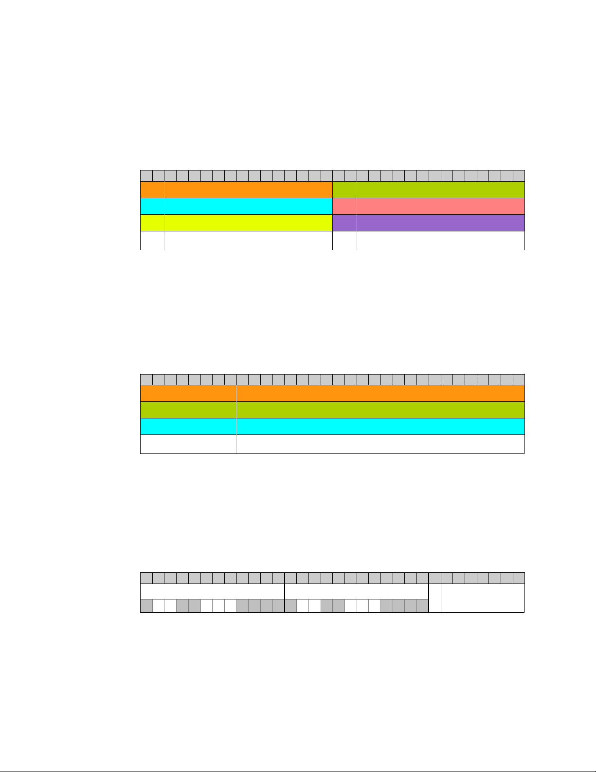
VITA-49 Radio Transport Protocol
{I14} Data Payload Format
6. Each I data is a signed two's-complement 14-bit sample with signed extended into
16-bit. Thus, each component is an integer ranging from -8192 to +8191 (or ±213).
7. The first I sample is in the upper 16-bit of each data word follows by the second I
sample in the lower 16-bit, as seen in Table 31.
Table 31: {I14} Data Payload Arrangement with Upper 2-bit Signed Extended to {I16}
31 30 29 28 27 26 25 24 23 22 21 20 19 18 17 16 15 14 13 12 11 10 9 8 7 6 5 4 3 2 1 0
0bxx
0bxx
0bxx
.
.
.
Item 1 (Sample 1 I14)
Item 3 (Sample 3 I14)
Item 5 (Sample 5 I14)
.
.
.
0bxx
0bxx
0bxx
.
.
.
Item 2 (Sample 2 I14)
Item 4 (Sample 4 I14)
Item 6 (Sample 6 I14)
.
.
.
Same conversion example as {I14Q14}.
{I24} Data Payload Format
8. Each data word is one I-component as seen in Table 32.
9. Each I data is a signed two's-complement 24-bit sample with signed extended into
32-bit. Thus, each component is an integer ranging from -8388608 to +8388607
(or ±223).
Table 32: {I24} Data Payload Arrangement with Upper 8-bit Signed Extended to {I32}
31 30 29 28 27 26 25 24 23 22 21 20 19 18 17 16 15 14 13 12 11 10 9 8 7 6 5 4 3 2 1 0
0bxxxxxxxx
0bxxxxxxxx
0bxxxxxxxx
.
.
.
Item 1 (Sample 1 I24)
Item 2 (Sample 2 I24)
Item 3 (Sample 3 I24)
.
.
.
Examples conversion:
• Given the big-endian bytes 0x0018FFFE, then I24 = 0x18FFFFE.
• Given the big-endian bytes 0xFF800034, then I24 = 0x800034 (or -8388556).
• Compute fractional value if needed: i/223.
Trailer Word Format
Table 33: Trailer Word Format
31 30 29 28 27 26 25 24 23 22 21 20 19 18 17 16 15 14 13 12 11 10 9 8 7 6 5 4 3 2 1 0
Enables State and Event Indicators E Associated Context
DV RL SI OR SL DV RL SI OR SL
State and Event Indicators and the associated Enable bits shall be positions as indicated
in Table 34.
Packet Count
1. For each Indicator bit in the State and Event Indicators field, there is a
corresponding Enable bit at the same position in the Enables field.
ThinkRF R5500 Real Time Spectrum Analyzer Programmer's Guide 37
Page 38

VITA-49 Radio Transport Protocol
2. When an Enable bit is set to 1, the corresponding indicator shall function as shown
in Table 34. Otherwise, the corresponding indicator shall not be considered valid.
3. Unused bits in the Enables field and the Indicators field shall be set to 0.
4. The E field shall be set to 0 to specify the Associated Context Packet Count field as
undefined.
5. The Associated Context Packet Count field is unused and shall be set to 0.
Table 34: Trailer Indicator and Enable Bits
Enable Bit Position Indicator Bit Position Indicator Name
30 18 Valid Data Indicator
29 17 Reference Lock Indicator
26 14 Spectral Inversion Indicator
25 13 Over-range Indicator
24 12 Sample Loss Indicator
6. The Valid Data Indicator, when set to 1, shall indicate that the data in the packet
is valid. When set to zero, it shall indicate that some condition exists that may
invalidate the data.
7. The Reference Lock Indicator, when set to 1, shall indicate all PLLs in the system
are locked and stable, and when set to 0, shall indicate one or all of the PLLs is not
locked or unstable. It is very crucial to check this indicator bit.
8. The Spectral Inversion Indicator, when set to 1, shall indicate that the signal
conveyed in the data payload has an inverted spectrum with respect to the
spectrum of the signal at the system Reference Point. When processing the data
payload, for plotting purpose for instance, follow the suggested solution in Table 35
to properly display the spectrum.
Important Note: When using :OUTput:MODE CONNector with :INPut:MODE SH or
SHN, the spectral inversion indicator is available through the GPIO port. Contact
ThinkRF's Support for further details (or see “Synchronized Sweep with IQout” AppNote
for important information).
9. The Over-range Indicator shall be set to 1 if any data value in the packet has
reached full scale at the input of the digitizer.
10. The Sample Loss Indicator, when set to 1, shall indicate that data overflow has
occurred before the current captured VRT packet, not within that current packet.
In other words, there are data dropped between the previous packet and the
current packet which has the sample loss indicator. The data between those two
packets are not continuous and contiguous.
Table 35 lists the conditions in which an indicator would signal an abnormal state and the
suggested resolutions.
38 ThinkRF R5500 Real Time Spectrum Analyzer Programmer's Guide
Page 39

VITA-49 Radio Transport Protocol
Table 35: Conditions Causing Abnormal Indicator State and Suggested Resolution
Indicator
Name
Valid Data 0 1) One or more PLLs failed to
Abnormal
State
lock.
Conditions Suggested Resolution
1) Try to reset the frequency or
restart the RTSA. If the condition
persists, contact ThinkRF's Support.
2) In HDR mode, the NB
ADC's filter has not settled.
Reference
Lock
Spectral
Inversion
Over-range 1 The over-range threshold is
Sample Loss 1 This condition occurs only in
0 One or more PLLs failed to
lock.
1 Spectral inversion occurs
when the frequency of the
local oscillator exceeds that of
the RF input signal being
processed. At some signal
frequency ranges input to the
R5500, the IF output spectrum
is inverted. Figure 10
illustrates an example.
the absolute full-scale of I or
Q data. For WB ADC, the
over-range threshold is at
Vpeak = 1.0 V; and for NB
ADC, Vpeak = 1.6 V.
Stream mode when the
internal buffer is full.
2) Discard the data packet and reacquire the data. This condition is
unlikely as the settle time is within
hundred of nanoseconds.
Same as 1) above
When this indicator is 1, either swap
each {I,Q} data point when both
{I,Q} components are available or
invert the output data bins of the
computed spectral power when
have {I} only data.
- Enable the :ATTentuator if it is not
yet on.
- If :ATTentuator is already on,
reduce the input level or the gain
settings.
Use a decimation value such that
the transfer rate matches that of the
capture rate.
Figure 10: An Example Illustrating Uninverted and Inverted Spectrums
ThinkRF R5500 Real Time Spectrum Analyzer Programmer's Guide 39
Page 40

SCPI Command Set
SCPI Command Set
This section is a SCPI reference guide for controlling the ThinkRF R5500 Real Time
Spectrum Analyzer. The R5500 supports the Standard Commands for Programmable
Instruments (SCPI) standard version 1999.0 as described in the following sections. SCPI
lends itself to a command line interface and scripting, is supported by the major
instrument vendors and provides a high level of familiarity for instrument users.
Note: ThinkRF's version of SCPI does not provide commands for network connection.
The R5500 receives SCPI commands and sends query responds over port 37001. See
Appendix A: Connecting to RTSA for more details.
SCPI Language Overview
In the early 1990s, a group of instrument manufacturers developed Standard Commands
for Programmable Instrumentation (SCPI) for controlling programmable instruments via a
communication link, such as RS232, USB, LAN, etc. SCPI specifies the command
structure and syntax using ASCII characters to provide some basic standardization and
consistency to the control commands. SCPI commands, hence, lend themselves to
communications with equipments via command line interface, scripting and/or
programming languages such as C/C++, MATLAB®, Python, etc.
The SCPI language is based on a hierarchical or tree structure as illustrated in Figure 11
an example command set. The top level of the tree is the root node, which is followed by
one or more lower-level nodes.
TRACe
BLOCk STReam SPPacket
STARt
Figure 11: SCPI Language Hierarchical or Tree Structure Example
SCPI defines a measurement function block that is directly applicable to the ThinkRF
RTSA. The measurement function converts a physical signal into an internal data form
that is available for formatting into bus data. It may perform the additional tasks of signal
conditioning and post-conversion calculation. The measurement function box is
subdivided into three distinct parts: INPut, SENSe, and CALCulate as seen in Figure 12.
STATus?STOP
40 ThinkRF R5500 Real Time Spectrum Analyzer Programmer's Guide
Page 41

INPut SENSeINPut CALCulate
Measurement Function
SCPI Command Set
Figure 12: SCPI Measurement Function Block
Refer to the Appendix C: SCPI Command Syntax section for the general SCPI command
syntax format and usage details.
IEEE Mandated SCPI Commands
These commands control and query the communication event/error and status registers
as defined in the Appendix D: SCPI Status and Event Registers section. They are
mandated by the IEEE.
Caution: The mandated IEEE SCPI commands are not affected by *RST command.
*CLS
The Clear Status (CLS) command clears the Status Byte register (STB), the standard
Event Status register (ESR), the standard Questionable status register, the standard
Operation Status register, and the error/event queue.
Syntax *CLS
Parameter/Response None
TRIGger
TRACe and
SWEep
*ESE/*ESE?
*ESE command enables bits in the ESE register. The decimal integer value entered is
the binary equivalent of the desired 8-bit mask. Bits enabled in ESE and set in ESR
register will result in the Standard Event Status Summary bit (bit 5) in the STB register
being set. This then allows the reading of ESR by using the *ESR? query command to
determine the cause.
*ESE? query returns the decimal sum of the enabled bits in the ESE register. The
decimal sum is the binary equivalent of the 8-bit mask.
See Figure 13 for the ESE/ESR register bits mapping.
Syntax *ESE <integer>
*ESE?
Parameter/Response <integer>
Allowable Values 0 - 255
ThinkRF R5500 Real Time Spectrum Analyzer Programmer's Guide 41
Page 42

SCPI Command Set
*ESR?
Query the standard Event Status Register (ESR), which returns the decimal sum of the
bits set in the ESR. The decimal sum is the binary equivalent of the 8-bit mask. Any
specific bit in the ESR will only appear set if and only if its event has occurred and the
corresponding bit in the ESE is also enabled.
See Figure 13 for the ESR register bits mapping.
Caution: This is a destructive read. Once queried, the register is cleared.
*IDN?
Returns the R5500's identification information string.
Syntax *ESR?
Parameter None
Response <integer>
Description Refer to the Appendix D: SCPI Status and Event Registers section
for the ESR register bit definition
Note: The model string returned will not include the options (ie. WBIQ, etc). To find out
which options a model has, use :SYSTem:OPTions? command.
Syntax *IDN?
Parameter None
Response “<Manufacturer>,<Model>,<Serial number>,<Firmware version>”
Data Type string
*OPC/*OPC?
*OPC (Operation Complete) command sets to confirm bit 0 in the ESR to 1 when all
commands received before *OPC or *OPC? have been completed.
*OPC? returns the ASCII character 1 in the Standard Event register indicating completion
of all pending operations. The query also stops any new commands from being
processed until the current processing is complete.
Syntax *OPC
*OPC?
Parameter None
Query Response 1
*RST
Resets the R5500 to its default settings. This includes stopping any running capture
mode and trigger mode, and also performs :SYSTem:FLUSh.
42 ThinkRF R5500 Real Time Spectrum Analyzer Programmer's Guide
Page 43

SCPI Command Set
*RST does not affect the registers or queues associated with the IEEE mandated
commands. Each non-IEEE mandated command description in this reference shows the
*RST value when affected.
Syntax *RST
Parameter/Response None
*SRE/*SRE?
The *SRE (Service Request Enable) command enables bits in the SRE register. The
decimal integer value entered is the binary equivalent of the desired 8-bit mask to be
enabled. Bits enabled in this register allow accessing the equivalent bits status in the
STB register.
*SRE? query returns the decimal sum of the enabled bits in the SRE register. The
decimal sum is the binary equivalent of the 8-bit mask.
See Figure 13 for the SRE/STB register bits mapping.
Syntax *SRE <integer>
*SRE?
Parameter/Response <integer>
*STB?
*STB? (Status Byte) query returns the decimal sum of the bits set in the STB register
without erasing its content. The decimal sum is the binary equivalent of the 8-bit mask.
Any specific bit in the STB will only appear set if and only if its event has occurred and
the corresponding bit in the SRE is also enabled.
See Figure 13 for the ESE/ESR register bits mapping and the Status Byte Register (SBR)
section of the Appendix D for the bits definition.
Syntax *STB?
Parameter None
Response <integer>
*TST?
*TST? (self-test) query initiates the device's internal self-test and returns one of the
following results:
• 0 - all tests passed.
• 1 - one or more tests failed.
Syntax *TST?
Parameter None
Response 0 | 1
Output Data Type Integer
ThinkRF R5500 Real Time Spectrum Analyzer Programmer's Guide 43
Page 44

SCPI Command Set
*WAI
*WAI (Wait-to-Continue) command suspends the execution of any further commands or
queries until all operations for pending commands are completed.
Parameter/Response None
SYSTem Commands
These commands control and query the communication event and status registers as
defined in the Appendix D: SCPI Status and Event Registers. They are the minimal
:SYSTem sets required in all SCPI instruments.
:SYSTem:ABORt
This command will cause the R5500 to stop the data capturing, whether in the manual
trace block capture, triggering or sweeping mode. The R5500 will be put into the manual
mode; in other words, process such as streaming, trigger and sweep will be stopped.
The capturing process does not wait until the end of a packet to stop, it will stop
immediately upon receiving the command.
Syntax *WAI
Syntax :SYSTem:ABORt
Parameter/Response None
*RST State N/A
Example
:SYST:ABORT
:SYSTem:CAPTure:MODE?
This command returns what the current RTSA data capture mode is (i.e. sweeping,
streaming or block mode).
When stream or sweep mode is stopped, block mode will resume.
Syntax :SYSTem:CAPTure:MODE?
Parameter None
Response BLOCK | STREAMING | SWEEPING
Output Data Type Character
*RST State BLOCK
Example
:SYST:CAPTURE:MODE?
:SYSTem:COMMunicate:LAN:APPLy
This command will apply the changes to the LAN settings and the embedded system will
automatically reconfigure the Ethernet to put in effect the new LAN setting. Once the
LAN settings are applied, they are not affected by power-on, :STATus:PRESET, or *RST.
44 ThinkRF R5500 Real Time Spectrum Analyzer Programmer's Guide
Page 45

SCPI Command Set
Caution: When changing from DHCP to STATIC mode, this command should to be sent
only when all the required LAN settings are set using the appropriate
:SYSTem:COMMunicate:LAN commands.
Syntax :SYSTem:COMMunicate:LAN:APPLy
Parameter/Response None
*RST State N/A
Examples
:SYST:COMM:LAN:APPLY
:SYSTem:COMMunicate:LAN:CONFigure
The set command will store the new LAN configuration type to be applied to the RTSA.
This command does not take effect until :SYSTem:COMMunicate:LAN:APPLy is sent
(please refer to the Caution note of the :APPLy command). Once the option is applied, it
is not affected by power-on, :STATus:PRESET, or *RST.
The query will return the option set or that of the actual current configuration if one is not
set. The CURRENT query will return what is currently and actually used by the RTSA's
LAN interface.
Note: *RST command cannot be used to set the box to its manufacturing default state of
DHCP. To set the box back to DHCP from a working STATIC mode, use this command
or the web-browser as mentioned in the RTSA User's Guide.
Syntax SYSTem:COMMunicate:LAN:CONFigure DHCP | STATIC
SYSTem:COMMunicate:LAN:CONFigure? [CURRENT]
Parameter Set: DHCP | STATIC
Query: [CURRENT]
Response DHCP | STATIC
I/O Data Type Character
*RST State N/A
Examples
:SYST:COMM:LAN:CONF DHCP
:SYST:COMM:LAN:CONF? CURRENT
:SYSTem:COMMunicate:LAN:DNS
The set command will store the new LAN DNS server address(es) to be applied to the
RTSA. This command does not take effect until :SYSTem:COMMunicate:LAN:APPLy is
sent (please refer to the Caution note of the :APPLy command). Once the setting is
applied, it is not affected by power-on, :STATus:PRESET, or *RST.
The query will return the LAN DNS address(es) set or that of the actual current
configuration if one is not issued. The CURRENT query will return what is currently and
actually used by the RTSA's LAN interface.
Syntax SYSTem:COMMunicate:LAN:DNS <main DNS>[,alternative DNS]
SYSTem:COMMunicate:LAN:DNS? [CURRENT]
ThinkRF R5500 Real Time Spectrum Analyzer Programmer's Guide 45
Page 46

SCPI Command Set
:SYSTem:COMMunicate:LAN:GATEway
The set command will store the new LAN gateway to be applied to the RTSA. This
command does not take effect until :SYSTem:COMMunicate:LAN:APPLy is sent (please
refer to the Caution note of the :APPLy command). Once the setting is applied, it is not
affected by power-on, :STATus:PRESET, or *RST.
The query will return the gateway address set or that of the actual current configuration if
one is not issued. The CURRENT query will return what is currently and actually used by
the RTSA's LAN interface.
Parameter Set: D.D.D.D[,D.D.D.D] where D = 0 – 255
Query: [CURRENT]
Response D.D.D.D[,D.D.D.D]
I/O Data Type String
*RST State N/A
Examples
SYSTEM:COMMUNICATE:LAN:DNS 208.67.110.0
SYST:COMM:LAN:DNS 208.67.110.0,208.67.100.10
SYSTEM:COMMUNICATE:LAN:DNS?
SYST:COMM:LAN:DNS? CURRENT
Syntax SYSTem:COMMunicate:LAN:GATEway <IPv4 address>
SYSTem:COMMunicate:LAN:GATEway? [CURRENT]
Parameter Set: D.D.D.D where D = 0 – 255
Query: [CURRENT]
Response D.D.D.D
I/O Data Type String
*RST State N/A
Examples
SYST:COMM:LAN:GATEWAY 102.101.0.13
SYSTEM:COMMUNICATE:LAN:GATEWAY?
SYST:COMM:LAN:GATE? CURRENT
:SYSTem:COMMunicate:LAN:IP
The set command will store the new LAN IP to be applied to the RTSA. This command
does not take effect until :SYSTem:COMMunicate:LAN:APPLy is sent (please refer to the
Caution note of the :APPLy command). Once the setting is applied, it is not affected by
power-on, :STATus:PRESET, or *RST.
The query will return the IP address set or that of the actual current configuration if one is
not issued. The CURRENT query will return what is currently and actually used by the
RTSA's LAN interface.
Syntax SYSTem:COMMunicate:LAN:IP <IPv4 address>
SYSTem:COMMunicate:LAN:IP? [CURRENT]
Parameter Set: D.D.D.D where D = 0 – 255
Query: [CURRENT]
Response D.D.D.D
I/O Data Type String
46 ThinkRF R5500 Real Time Spectrum Analyzer Programmer's Guide
Page 47

SCPI Command Set
*RST State N/A
Examples
SYST:COMM:LAN:IP 101.125.1.16
SYSTEM:COMM:LAN:IP?
SYST:COMM:LAN:IP? CURRENT
:SYSTem:COMMunicate:LAN:MTU
The set command will store the new LAN MTU (maximum transfer unit, in bytes) to be
applied to the RTSA. This command does not take effect until
:SYSTem:COMMunicate:LAN:APPLy is sent (please refer to the Caution note of the
:APPLy command). Once the setting is applied, it is not affected by power-on,
:STATus:PRESET, or *RST. The factory default value is 1500 bytes.
The query will return the MTU set or that of the actual current configuration if one is not
issued. The CURRENT query will return what is currently and actually used by the
RTSA's LAN interface.
Note: Use this command to change the maximum network packet or frame size in a transaction;
however, changing the MTU value could affect the transfer rate or causing lost of network packets
if the packets have an MTU value larger than that permitted by your network. Check with your
network administrator before changing this value.
Syntax SYSTem:COMMunicate:LAN:MTU <valid MTU value in bytes>
SYSTem:COMMunicate:LAN:IP? [CURRENT]
Parameter Set: 576 – 1500 bytes
Query: [CURRENT]
Response Integer
I/O Data Type Integer
*RST State N/A
Examples
SYST:COMM:LAN:MTU 1400
SYSTEM:COMM:LAN:MTU?
SYST:COMM:LAN:MTU? CURRENT
:SYSTem:COMMunicate:LAN:NETMask
The set command will store the new LAN netmask address to be applied to the RTSA.
This command does not take effect until :SYSTem:COMMunicate:LAN:APPLy is sent
(please refer to the Caution note of the :APPLy command). Once the setting is applied, it
is not affected by power-on, :STATus:PRESET, or *RST.
The query will return the maskaddress set or that of the actual current configuration if one
is not issued. The CURRENT query will return what is currently and actually used by the
RTSA's LAN interface.
ThinkRF R5500 Real Time Spectrum Analyzer Programmer's Guide 47
Page 48

SCPI Command Set
:SYSTem:COMMunicate:NTP
This command sets or queries the NTP configuration server address. When set, this
command will accept only one server IP address. However, the query response will
return the IP address set through this command or up to three domain/IP addresses set
through R5500's web administrative page.
Syntax SYSTem:COMMunicate:LAN:NETMask <address>
SYSTem:COMMunicate:LAN:NETMask? [CURRENT]
Parameter Set: D.D.D.D where D = 0 – 255
Query: [CURRENT]
Response D.D.D.D
I/O Data Type String
*RST State N/A
Examples
SYST:COMM:LAN:NETMASK 255.255.255.0
SYSTEM:COMMUNICATE:LAN:NETM?
SYST:COMM:LAN:NETM? CURRENT
Syntax SYSTem:COMMunicate:NTP <address>
SYSTem:COMMunicate:NTP?
Parameter <IP Address D.D.D.D>, where D = 0 – 255
Response <web/IP addr>[,<web/IP addr>[,<web/IP addr>]]
I/O Data Type String
*RST State N/A
Examples
SYSTEM:COMMUNICATE:NTP 129.6.15.28
SYST:COMM:NTP?
Note: This feature could also be set through R5500's administrative web page, with up
to 3 domain/IP addresses can be entered.
:SYSTem:ERRor[:NEXT]?
This query returns the oldest uncleared error code and message from the SCPI
error/event queue. When there are no error messages, the query returns 0,"No error".
*RST does not affect the error queue.
Note: It is recommended to do this query command after each non-query command is
sent to ensure that the non-query command is executed without error. Since each error
message is queued into a buffer, if multiple commands have been sent follow by only one
:SYSTem:ERRor[:NEXT]? command, it would be uncleared which command has resulted
in which error.
Syntax :SYSTem:ERRor[:NEXT]?
Parameter None
Response <error code>,<description>
Output Data Type <integer>,<string>
48 ThinkRF R5500 Real Time Spectrum Analyzer Programmer's Guide
Page 49

SCPI Command Set
Description Refer to the Appendix D: SCPI Status and Event Registers section
Example
:SYST:ERR?
:SYSTem:ERRor:ALL?
This query returns all the uncleared error codes and messages from the SCPI error/event
queue. If there are no error messages, the query returns 0,"No error".
Syntax :SYSTem:ERRor:ALL?
Parameter None
Response <error code>,<description>{,<error code>,<description>}
Output Data Type <integer>,<string>{,<integer>,<string>}
Description Refer to the Appendix E: SCPI Error Codes Used section
Example
:SYST:ERR:ALL?
:SYSTem:FLUSh
This command clears the R5500's internal data storage buffer of any data that is waiting
to be sent. Thus, it is recommended that the flush command should be used when
switching between different capture modes to clear up the remnants of data in the RTSA.
Caution: Issuing :SYSTem:FLUSh any time during streaming or sweeping mode will
cause the stream or sweep capture to stop (abort) and switch automatically to block
capture mode.
Note: Flush command only handles the RTSA's internal buffer storage. The host
application should ensure that the socket buffer is also cleared up of any potential data in
the socket buffer. This can be done by calling the receive socket (non-blocking) until no
data is returned. With Streaming or Sweeping, the start ID in a VRT extension packet
marks the beginning of packets belonging to the new stream or sweep. This helps to
distinct old packets from new packets.
Syntax :SYSTem:FLUSh
Parameter/Response None
*RST State N/A
Examples
:SYST:FLUSH
:SYSTem:LOCK:HAVE?
This query returns the current lock state of the specified task.
Syntax :SYSTem:LOCK:HAVE? ACQuisition
Parameter ACQuisition
Input Data Type Character
Response 1 | 0
ThinkRF R5500 Real Time Spectrum Analyzer Programmer's Guide 49
Page 50

SCPI Command Set
:SYSTem:LOCK:REQuest?
This query attempts to attain the lock on the R5500 for a specific task, such as data
acquisition. The query returns 1 when lock is successful or 0 if it fails.
Attaining a lock is equivalent to having the sole ownership for that task. This prevents
multiple connected applications from doing the same task that would result in an
erroneous operation or feedback from the R5500. The R5500's system lock ownership
works in the following manner:
• The first application to connect to R5500 will automatically have the lock. The next
• When there is only one application connected (or the last one remained), that
• The last application that requested successfully has the lock until another
1 – Have the lock
0 – Does not have the lock
Output Data Type Boolean
*RST State N/A
Examples
:SYST:LOCK:HAVE? ACQ
application will need to perform this query request to attain the lock.
application will automatically has the lock.
application attained it.
Any application that doesn't have the specific lock will not be able to perform that task.
Note: When a TCP/IP socket connection is not exited properly, that socket might
continue to exist in the R5500 server for a few minutes. This could affect a situation
when only one application is used to connect to the R5500 as reconnection by that
application might not get the lock. This application would then need to request the lock.
Syntax :SYSTem:LOCK:REQuest? ACQuisition
Parameter ACQuisition
Input Data Type Character
Response 1 | 0
1 – Successfully locked
0 – Failed to lock
Output Data Type Boolean
*RST State N/A
Example
:SYST:LOCK:REQ? ACQ
:SYSTem:OPTions?
This command queries the hardware option(s) or features that a particular RTSA model
supported. The response string contains comma separated 3-digit values to represent
the options. See Table 36 for the translated list. For example, R5500-4XX-WBIQ would
have code 003 returned in the response string to indicate wideband IQ option.
50 ThinkRF R5500 Real Time Spectrum Analyzer Programmer's Guide
Page 51

SCPI Command Set
Syntax :SYSTem:OPTions?
Parameter None
Response <xxx>{,<xxx>}
Output Data Type Comma separated 3-digit value (ex: 000, 001, 002)
*RST State None
Example
:SYST:OPT?
Table 36: RTSA Option Codes and the Corresponding Description
Option Code Description Related SCPI Command
000 No Special Option
003 R5500-4XX-WBIQ1 Model None
:OUTput:MODE is defaulted to DIGitizer
1
WBIQ are special R5500 variants, not available on all R5500s. Contact ThinkRF for more details
on the usage of these variants.
:SYSTem:SYNC:MASTer
This command sets the RTSA unit to be the master or slave for a synchronization trigger
system with multiple units, in which only one unit can be the master.
The master sends a sync-word or pulse (set through :TRIGger:TYPE or
:SWEep:ENTRy:TRIGger:TYPE) via its GPIO to that of the slaves to indicate the
beginning of a capture. The master RTSA itself will has an internal loop-back of the
synchronization signal it sent out.
Syntax :SYSTem:SYNC:MASTer <Boolean>
:SYSTem:SYNC:MASTer?
Parameter ON | OFF | 1 | 0
Input Data Type Integer | Character
Query Response 0 | 1
Output Data Type Integer
*RST State 0
Examples
:SYSTem:SYNC:MASTER ON
:SYSTem:SYNC:MAST?
:SYSTem:SYNC:WAIT
This command sets the delay time in nanoseconds that a RTSA system must wait after
receiving the satisfying trigger signal and before performing data capture. The delay time
should be a multiple of 8 nsec as the RTSA system runs with a 125MHz clock.
Syntax :SYSTem:SYNC:WAIT <integer>
:SYSTem:SYNC:WAIT?
Parameter/Response
Allowable Values 0 – 4294967295 (or 2
*RST State 0
<integer>
32
-1)
ThinkRF R5500 Real Time Spectrum Analyzer Programmer's Guide 51
Page 52

SCPI Command Set
Examples
:SYSTem:SYNC:WAIT 120
:SYSTem:SYNC:WAIT?
:SYSTem:VERSion?
This query returns the SCPI version number that the instrument software complies with.
Syntax :SYSTem:VERSion?
Parameter None
Response <NR2>
Output Data Type String (decimal number YYYY.V)
Example :SYST:VERS
:SYSTem:DATE
This command sets or queries the current date of the R5500. When the date is set, the
change is applied to the real time clock (RTC) of the R5500 system, and the
:SYSTem:TIME:SYNC field is changed to DISable automatically. The date returned is
representative of the current time mode that is UTC.
This command is not affected by a power-on, factory reset, or *RST command.
Syntax :SYSTem:DATE <integer>,<integer>,<integer>
:SYSTem:DATE?
Parameters/Response <year>,<month>,<date>
I/O Data Type String (comma separated integers)
Allowable Values Year: YYYY - requires a four digit integer, 1900 - 9999
Month: 1 - 12
Date: 1 - 31
*RST State N/A
Examples
:SYST:DATE 2012,12,2
:SYSTEM:DATE?
:SYSTem:TIME
This command sets or queries the current time of the R5500. When the time is set, the
change is applied to the RTC of the R5500 system, and the :SYSTem:TIME:SYNC field
is changed to DISable automatically. The time returned is representative of the current
time mode that is UTC.
This command is not affected by a power-on, factory reset, or *RST command.
Syntax :SYSTem:TIME <integer>,<integer>,<integer>[,<integer>]
:SYSTem:TIME?
Parameters <hour>,<minute>,<second>[,<millisecond>]
Response <hour>,<minute>,<second>[,<millisecond>] in UTC
I/O Data Type String (comma separated integers)
Allowable Values Hour: 0 - 23
Minute: 0 - 59
52 ThinkRF R5500 Real Time Spectrum Analyzer Programmer's Guide
Page 53

SCPI Command Set
Second: 0 – 59
Millisecond: 0 - 999
*RST State N/A
Examples
:SYST:TIME 10,30,15
:SYSTEM:TIME?
:SYSTem:TIME:ADJust
This command adjusts the system time relative to its current time.
Further information will be provided in a future revision of this document.
Syntax :SYSTem:TIME:ADJust <integer> [unit]
:SYSTem:TIME:ADJust?
Parameters <second or sub-second> [unit]
Allowable Values 0 – 4294967295 (or 232 - 1)
Response <integer>
Default I/O unit ns
*RST State 0
Examples
:SYST:TIME:ADJUST 10 ns
:SYSTEM:TIME:ADJUST?
:SYSTem:TIME:SYNC
This command selects the time synchronization source for R5500 and the query returns
the source selected. Choosing NTP (Network Time Protocol) as the synchronization
source will impact the system real time clock (RTC), causing it to update either at a
continuous interval or one time only. When :SYSTem:DATE and/or :SYSTem:TIME
commands are used to change the time, the source will automatically be changed to
DISable.
*RST does not affect this command. At factory install, the synchronization is defaulted to
disabled.
Syntax :SYSTem:TIME:SYNC DISable | NTP,{ONCE | CONTinuous}
:SYSTem:TIME:SYNC?
Parameter DISable | NTP,{ONCE | CONTinuous}
Response DISabled | NTP,{ONCE | CONTinuous}
I/O Data Type Character | String (comma separated characters)
*RST State DISable
Examples
:SYST:TIME:SYNC NTP,ONCE
:SYST:TIME:SYNC DISABLE
:SYSTEM:TIME:SYNC?
:SYSTem:TIME:SYNC:STATus?
This command returns the current status of the time synchronization.
Further information will be provided in a future revision of this document.
ThinkRF R5500 Real Time Spectrum Analyzer Programmer's Guide 53
Page 54

SCPI Command Set
Syntax :SYSTem:TIME:SYNC:STATus?
Parameter None
Response TBD
Data Type TBD
Examples
:SYST:TIME:SYNC:STAT?
54 ThinkRF R5500 Real Time Spectrum Analyzer Programmer's Guide
Page 55

STATus Commands
N/A
N/A
TIM E
POWer
TEM Peratur e
FREQ uency
N/A
N/A
CALI brat ion
TBD
TBD
TBD
TBD
N/A
N/A
Not used
0
1
2
3
4
5
6
7
8
9
10
11
12
13
14
15
0
1
2
3
4
5
6
7
8
9
10
11
12
13
14
15
0
1
2
3
4
5
6
7
8
9
10
11
12
13
14
15
Co nditio n Stat us Ena ble
QU E S ti ona ble R egi ster s
CALIb rating
SET Tling
N/A
TBD
N/A
TRIG gering
N/A
COR Rect ing
TBD
N/A
N/A
N/A
N/A
N/A
PRO Gram Runn ing
Not Used
0
1
2
3
4
5
6
7
8
9
10
11
12
13
14
15
0
1
2
3
4
5
6
7
8
9
10
11
12
13
14
15
0
1
2
3
4
5
6
7
8
9
10
11
12
13
14
15
OP E R a tion Re gisters
Oper ation Co mplete (O PC)
N/A
Quer y Er ror (QYE)
Device Dep endent E rro r (D DE)
Execu tion Err or ( EXE)
Comm and E rror ( CME)
Not Used
Pow er O N (PON )
0
1
2
3
4
5
6
7
*ES R? *E SE
Stan dar d E ven t
Status R egister (ESR )
0
1
2
3
4
5
6
7
N/A
N/A
Erro r/Event Que ue (EAV)
Ques tiona ble Reg ister
Mess age Available (M AV)
Stan dard ES R
Requ est Serv ice (R QS)
Oper ation Reg ister
0
1
2
3
4
5
6
7
*ST B? *S RE
Status B y te ( ST B)
Se rvic e R equ est Ena ble (SR E )
0
1
2
3
4
5
6
7
.
.
.
Er ro r/E v en t Q ueu e
Summa ry of IE E E 4 88. 2 Status Stru cture R egister s
Co nditio n Stat us Ena ble
ThinkRF R5500 Real Time Spectrum Analyzer Programmer's Guide 55
SCPI Command Set
Figure 13: Status Reporting Structure with Status & Enable Registers
The STATus commands control the SCPI-defined status-reporting structures as
illustrated in Figure 13.
SCPI defines the QUEStionable, OPERation, Instrument SUMmary and INSTrument
registers in addition to those in IEEE 488.2. These registers conform to the IEEE 488.2
specification and each may be comprised of a condition register, an event register, an
enable register, and negative and positive transition filters.
Page 56

SCPI Command Set
SCPI also defines an IEEE 488.2 queue for status. The queue provides a human
readable record of instrument events. The application programmer may individually
enable events into the queue. :STATus:PRESET enables errors and disables all other
events. If the summary of the queue is reported, it shall be reported in bit 2 of the status
byte register. A subset of error/event numbers is defined by SCPI.
:STATus:OPERation[:EVENt]?
This command queries the standard Operation Status Register (OSR) for any event. The
query returns the decimal sum of the bits set in the OSR. The decimal sum is the binary
equivalent of the 16-bit mask. The last bit is unused. Any specific bit in the OSR will only
appear set if and only if its event has occurred and the corresponding bit in the OSE is
also enabled (refer to Appendix D: SCPI Status and Event Registers).
Caution: This query clears all bits in the register to 0.
See Figure 13 for the Operation Status register bits mapping.
Syntax :STATus:OPERation[:EVENt]?
Parameter None
Response <integer>
Output Values 0 – 32767 (2
*RST State None
Example
:STAT:OPER?
15
-1)
:STATus:OPERation:CONDition?
This command queries the standard Operation Condition Register (OCR) for any
questionable event. The query returns the decimal sum of the bits set in the OCR. The
decimal sum is the binary equivalent of the 16-bit mask. The last bit is unused. Any
specific bit in the OCR will only appear set if and only if its event has occurred and the
corresponding bit in the OSE is also enabled (see :STATus:OPERation:ENABle section).
The content of the OCR remains unchanged after it is read.
The data in this register is continuously updated to reflect the most current conditions.
See Figure 13 for the Operation Condition register bits mapping.
Syntax :STATus:OPERation:CONDition?
Parameter None
Response <integer>
Output Values 0 – 32767 (2
*RST State None
Example
:STAT:OPER:COND?
15
-1)
56 ThinkRF R5500 Real Time Spectrum Analyzer Programmer's Guide
Page 57

SCPI Command Set
:STATus:OPERation:ENABle
This command enables or queries bits in the Operation Enable register (OER). The
decimal integer value entered is the binary equivalent of the desired 16-bit mask to be
enabled. Bits enabled in this register allow accessing the equivalent bits status in the
OSR and OCR registers.
Bits enabled in OER and set in OSR/OCR register will result in the Standard Operation
Status Summary bit (bit 7) in the STB register being set. See Figure 13.
Syntax :STATus:OPERation:ENABle <integer>
:STATus:OPERation:ENABle?
Parameter/Response <integer>
Allowable Values 0 – 32767 (2
*RST State 0
Examples
:STAT:OPER:ENAB 256
15
-1)
:STAT:OPER:ENAB?
:STATus:PRESET
This command presets the R5500 (similar to *RST), and OSE and QSE to zero.
Syntax :STATus:PRESET
Parameter/Response None
:STATus:QUEStionable[:EVENt]?
This command queries the standard Questionable Status Register (QSR) for any event.
The query returns the decimal sum of the bits set in the QSR. The decimal sum is the
binary equivalent of the 16-bit mask. The last bit is unused. Any specific bit in the QSR
will only appear set if and only if its event has occurred and the corresponding bit in the
QSE is also enabled (refer to Appendix D: SCPI Status and Event Registers).
Caution: This query clears all bits in the register to 0.
See Figure 13 for the Questionable Status register bits mapping.
Syntax :STATus:QUEStionable[:EVENt]?
Parameter None
Response <integer>
Output Values 0 – 32767 (2
*RST State None
Example
:STAT:QUES?
15
-1)
:STATus:QUEStionable:CONDition?
This command queries the standard Questionable Condition Register (QCR) for any
questionable event. The query returns the decimal sum of the bits set in the QCR. The
ThinkRF R5500 Real Time Spectrum Analyzer Programmer's Guide 57
Page 58

SCPI Command Set
decimal sum is the binary equivalent of the 16-bit mask. The last bit is unused. Any
specific bit in the QCR will only appear set if and only if its event has occurred and the
corresponding bit in the QSE is also enabled (refer to Appendix D: SCPI Status and
Event Registers). The content of the QCR remains unchanged after it is read.
The data in this register is continuously updated to reflect the most current conditions.
See Figure 13 for the Questionable Condition register bits mapping.
:STATus:QUEStionable:ENABle
This command enables bits in the Questionable Enable register (QER). The decimal
integer value entered is the binary equivalent of the desired 16-bit mask to be enabled.
Bits enabled in this register allow accessing the equivalent bits status in the QSR and
QCR registers.
Syntax :STATus:QUEStionable:CONDition?
Parameter None
Response <integer>
Output Values 0 – 32767 (2
*RST State None
Example
:STAT:QUES:COND?
15
-1)
Bits enabled in QER and set in QSR/QCR register will result in the Standard
Questionable Status Summary bit (bit 3) in the STB register being set. See Figure 13.
Syntax :STATus:QUEStionable:ENABle <integer>
:STATus:QUEStionable:ENABle?
Parameter/Response <integer>
Output Values 0 – 32767 (2
*RST State 0
Examples
:STAT:QUES:ENAB 256
15
-1)
:STAT:QUES:ENAB?
:STATus:TEMPerature?
This command queries the RTSA's internal temperature provided by one or more
temperature sensors. The response field varies depending on how many sensors are
available in a RTSA model. The R5500 model, for instance, returns comma separated
values for the sensors at the RF, Mixer and Digital sections.
Syntax :STATus:TEMPerature?
Parameter None
Response <NRf>{,<NRf>}
For R5500: <RF>,<Mixer>,<Digital>
Output Data Type Float
Unit degrees Celsius
*RST State None
58 ThinkRF R5500 Real Time Spectrum Analyzer Programmer's Guide
Page 59

INPut Commands
:INPut:ATTenuator
This command sets or queries the fix attenuation of the R5500's RFE.
Note: This command applies to R5500-308, -408 and their variants only. It is not
applicable for -418 and -427 and their variants, see :INPut:ATTenuator:VARiable
command instead.
Query Response 0 | 10 | 20 | 30
Output Data Type Integer
Syntax :INPut:ATTenuator <integer>
:INPut:ATTenuator?
Parameter 0 | 10 | 20 | 30 [dB]
Input Data Type Integer, optional character unit
*RST State 30
Examples
:INP:ATT 20
:INPUT:ATT?
SCPI Command Set
:INPut:ATTenuator:VARiable
This command sets or queries the variable attenuation of the R5500.
Notes:
- This command applies to R5500-418, -427, and their variants only. For R5500-308,
-408 and their variants, see :INPut:ATTenuator command instead.
- Recommend setting the attenuation to 0 dB for best performance
Syntax :INPut:ATTenuator:VARiable <NRf [dB]>
:INPut:ATTenuator?
Parameter 0 | 10 | 20 | 30 [dB]
Input Data Type Integer, optional character unit
Query Response 0 | 10 | 20 | 30
Output Data Type Integer
*RST State 30
Examples
:INP:ATT:VAR 0
:INPUT:ATT:VAR?
:INPut:GAIN
This command sets or queries the input gain stage for a RTSA. The number of gain
stages is dependent on the models as listed below. Any out of range index will result in
an Execution Error response (see Error and Event Queue section). Contact ThinkRF's
Support for further details and the gain ranges of each stage.
ThinkRF R5500 Real Time Spectrum Analyzer Programmer's Guide 59
Page 60

SCPI Command Set
Note: The reference level context information (see page 31) is only valid when all the
gain stages are enabled for R5500-418, 427 and their variants.
Table 37: Performance of The Gain Settings of R5500-418, 427 and Their Variants
Syntax :INPut:GAIN <Index> <Boolean>
:INPut:GAIN? <Index>
Parameter <Integer> <ON | OFF | 1 | 0>
Input Data Type <Integer> <Character | Integer>
Allowable Values Boolean: ON | OFF | 1 | 0
Index: Varies depending on the product model
- R5500-408 & its variant: No controllable gain stage
- R5500-418, 427 & their variants: 1, 2. See Table 37 for the gain
settings' performance
Query Response 1 | 0
Output Data Type Integer
*RST State 1 for all available stages
Examples
:INPUT:GAIN 2 ON
:INP:GAIN? 1
:INP:GAIN 1 0
Stage 1 Stage 2 Performance
0 (OFF) 0 (OFF) High Saturation Level
0 (OFF) 1 (ON) Not Optimal*
1 (ON) 0 (OFF) Good DANL and Saturation Level
1 (ON) 1 (ON) Best DANL
* This setting is not recommended.
:INPut:GAIN:HDR
This command sets or queries variable NB IF gain of the HDR signal path.
Syntax :INPut:GAIN:HDR <NR1 [unit]>
:INPut:GAIN:HDR? [MAX | MIN]
Parameter <NR1 [unit]>
Input Data Type Signed integer [character]
Allowable Values -10 to 34
Query Response <NR1>
Output Data Type Signed integer
Default I/O unit dB
*RST State 25
Examples
60 ThinkRF R5500 Real Time Spectrum Analyzer Programmer's Guide
:INPUT:GAIN:HDR -5
:INP:GAIN:HDR 20 dB
:INP:GAIN:HDR?
Page 61

SCPI Command Set
:INPut:MODE
This command sets or queries the R5500's RFE mode of operation.
Notes: The RFE modes affect the data packing method due to the different output data
width. The type of DSP applied would also change the data output of some of the modes
as well. For example, SH mode with frequency shift would change from I14 only data to
I14Q14 data output. The VRT's Stream ID would identify the format accordingly. See Table
2: Radio RFE Modes and DSP Data Output Formats (page 16) and VRT's IF Data
Packet Class (page 34).
- It is also important to see Table 2 for the IBW of each mode and the related notes.
- If :OUTput:MODE CONNector is to be used with SH or SHN mode, see the Important
Note listed under that command.
Syntax :INPut:MODE ZIF | DD | HDR | SH | SHN
:INPut:MODE?
Parameter/Response ZIF | DD | HDR | SH | SHN
I/O Data Type Character
*RST State
Examples
Product version dependent
:INP:MODE SH
:INPUT:MODE?
1
The RFE mode availability is product dependent. Hence, the *RST state and the initial power-up
default would be different depending on the product version.
1
SOURce Commands
:SOURce:REFerence:PLL
This command selects and queries the 10MHz reference clock source, whether it be via
the internal source or through the external SMA connector.
Caution: When the external 10MHz reference is used, its reference level must be
between -10dBm and 0dBm. Exceeding the level of 0dBm will result in permanent
damage to the internal clock circuit. Additionally, the 10MHz reference must be powered
down prior to powering down the R5500.
Parameter/Response INT | EXT
I/O Data Type Character
Syntax :SOURce:REFerence:PLL INT | EXT
:SOURce:REFerence:PLL?
*RST State INT
Examples
:SOURCE:REF:PLL INT
:SOUR:REF:PLL?
ThinkRF R5500 Real Time Spectrum Analyzer Programmer's Guide 61
Page 62

SCPI Command Set
:SOURce:REFerence:PLL:RESET
This command resets the 10MHz reference clock in to the internal source.
Parameter/Response None
SENSe Commands
[:SENSe]:DECimation
This command sets or queries the rate of decimation of samples in a trace capture.
When the rate is set to 1 (or OFF), no decimation is performed on the trace capture. The
decimation range varies depending on the RFE modes as described below.
In HDR mode, the decimation is done directly by the on-board NB ADC. The decimation
value supported by this mode is 1, 2 and 4.
Syntax :SOURce:REFerence:PLL:RESET
*RST State INT
Examples
:SOURCE:REF:PLL:RESET
In the remaining RFE modes, R5500 uses DDC to provide 10 levels of decimation of
values 4, 8, 16, 32, 64, 128, 256, 512, 1024 (i.e. decimation rate = 2
level
where level = 2 –
10). The decimation process consists of CIC and FIR filters, each type of filters with its
own decimator. The decimator captures one sample at every <integer> number of
samples. The filters are arranged in the following manner:
• For the decimation rate of 4, only a FIR filter with a fixed decimation by 4 is used,
CIC filter is bypassed.
• For the decimation rates of 8 to 1024, a 4-stage CIC of rate 4 to 512 is applied first
for each I and/or Q data. The resulting I and/or Q data pipes are then passed to a
FIR filter with a fixed decimation of 2 to arrive at the rate set. For example, for a
rate of 16, I and Q data will first pass-through the CIC filters with a decimation rate
of 8. The CIC output will be further decimated by 2 by the FIR filter which has a
fixed decimation rate of 2.
Note: When in SH/SHN mode and a decimation is on, the R5500 (non-WBIQ models)
will automatically be shifted by 35MHz to the zero IF before decimation is applied. This
implies the VRT data output will be {I,Q} for SH/SHN with decimation.
Syntax :SENSe:DECimation OFF | <integer>
:SENSe:DECimation? [MAX | MIN]
Parameter OFF | <decimation value>
Input Data Type Integer | Character
Allowable Values In HDR mode:
OFF, 1, 2, 4
For ZIF, SH, SHN modes:
OFF, 1, 4, 8, 16, 32, 64, 128, 256, 512 and 1024
1 Equivalents to decimation off.
62 ThinkRF R5500 Real Time Spectrum Analyzer Programmer's Guide
Page 63

SCPI Command Set
Query Response In HDR mode:
1, 2, 4
For ZIF, SH, SHN modes:
1, 4, 8, 16, 32, 64, 128, 256, 512 and 1024
Output Data Type Integer
*RST State 1
Examples
:DEC 16
:SENSE:DEC OFF
[:SENSe]:FREQuency:CENTer
This command sets or queries the center frequency of the RTSA with one exception. For
the DD mode, this command does not apply (however, [:SENSe]:FREQuency:SHIFt
command is still applicable to those modes).
The frequency resolution varies depending on the RFE modes of operation. ZIF, SH and
SHN signal paths utilize the WB ADC; thus, the frequency tuning resolution is 10Hz. For
those receiver modes, the resolution can be down to the nearest 1Hz resolution
(±0.23Hz) using [:SENSe]:FREQuency:SHIFt command. While for HDR receiver mode,
the frequency resolution is 10Hz without further frequency shifting capability. Refer to RF
Receiver Front-End (page 16) for more details.
For example, the system is in ZIF mode, to tune to a frequency of 2441.16MHz require
the sending of two commands: [:SENSe]:FREQuency:CENTer 2441.1MHz and
[:SENSe]:FREQuency:SHIFt 6kHz. The set values can be verified by querying. If a valid
frequency with an inappropriate resolution is set, the frequency value will be rounded
down to the nearest valid resolution, no error is set.
In addition, depending on the product models, the allowable range of programmable
frequencies varies. Check with your product's data sheet. For example, R5500-408 has
a range of 0.1 to 8GHz, while R5500-427 has 0.1 to 27GHz.
Syntax [:SENSe]:FREQuency:CENTer <NRf [unit]>
[:SENSe]:FREQuency:CENTer? [MAX | MIN]
Parameters <center frequency [unit]>
Input Data Type NRf [character]
Allowable Values Varies depending on the product model
Query Response <integer>
Default I/O Unit Hz
*RST State 2400000000
Examples
:FREQ:CENTER 2441.5 MHz
SENSE:FREQ:CENT 200000000
:FREQ:CENT 2.01 GHZ
SENSe:FREQ:CENTer?
[:SENSe]:FREQuency:IF?
This command queries the IF frequencies that are used for the current input mode and
center frequency.
ThinkRF R5500 Real Time Spectrum Analyzer Programmer's Guide 63
Page 64

SCPI Command Set
This command works in all R5500 models but the number and significance of the IF
frequencies will vary depending on the model and configured options (see
:SYSTem:OPTions? command). The IF index can be specified either as a positive
number (1 to N) where 1 indicates the first IF mixing stage after the input from the front
end , or as a negative number (-1 to -N) where -1 indicates the last IF before the digitizer
input or at the output connector in certain models (e.g. HIF option). If the input index is
beyond the number of available IFs, :SYSTem:ERRor[:NEXT]? will return a -222,“Data
out of range” response.
Syntax [:SENSe]:FREQuency:IF? <non-zero integer>
Parameters <IF index>
Input Data Type Non-zero Integer
Allowable Values Varies depending on RFE input mode, frequency, model and options
Query Response IF frequency
Output Data Type <integer>
Default Output Unit Hz
*RST State N/A
Examples
SENSE:FREQ:IF? -1
[:SENSe]:FREQuency:INVersion?
This query only command is used to determine if a spectral inversion is required on the
data output at the IQ OUT connector at a given frequency, regardless of the DSP mode
enabled. See Table 35 for more information on spectral inversion.
This command is not available for the sweep entry subset of commands. However, this
command can be used iteratively during say initialization stage to query the frequency
range of interest. The results can than be stored in a look-up table, for example.
Syntax [:SENSe]:FREQuency:INVersion? [NRf [unit]]
Parameters Optional [center frequency [unit]]
Input Data Type [Double [character]]
Default Input Unit Hz
Allowable Values Varies depending on the product model
Query Response 1 | 0
where 1 is equivalent to the inversion is required
Output Data Type Integer
*RST State N/A
Examples
SENSE:FREQ:INV? 2441.5 MHz
FREQ:INV?
[:SENSe]:FREQuency:LOSCillator?
This command queries the frequency of the local oscillator (LO) 1, 2 or 3 in
corresponding to current the RTSA's center frequency set.
64 ThinkRF R5500 Real Time Spectrum Analyzer Programmer's Guide
Page 65

SCPI Command Set
Syntax [:SENSe]:FREQuency:LOSCillator? <1 | 2 | 3>
Parameter None
Query Response <integer>
0 := LO Off
*RST State 1
Example
:FREQ:LOSC? 2
[:SENSe]:FREQuency:SHIFt
This command sets or queries the frequency shift value. A negative shift value
corresponds to a left shifting.
This command is also used in additional to [:SENSe]:FREQuency:CENTer to fine tune
the RTSA down to 1Hz resolution.
Note: Frequency shift mode is not available for some RFE modes of operation. Also,
when enabled, it would affect the data output format of some RFE modes. See Table 2:
Radio RFE Modes and DSP Data Output Formats (page 16).
Syntax [:SENSe]:FREQuency:SHIFt <NRf [unit]>
[:SENSe]:FREQuency:SHIFt? [MAX | MIN]
Parameters <Frequency [unit]>
Input Data Type Float [character]
Allowable Values -62.5 – 62.5MHz
Query Response <integer>
Default I/O Unit Hz
*RST State 0
Examples
:FREQ:SHIF -10.5 MHz
SENSE:FREQ:SHIFT 20000000.0
SENSe:FREQ:SHIFT?
FREQ:SHIFT? MAX
[:SENSe]:LOCK:REFerence?
This command queries the lock status of the PLL reference clock in the digital card.
Syntax [:SENSe]:LOCK:REFerence?
Parameter None
Query Response 0 | 1
1 Reference PLL is locked
0 Reference PLL is not locked
Output Data Type Integer
*RST State N/A
Example
ThinkRF R5500 Real Time Spectrum Analyzer Programmer's Guide 65
LOCK:REF?
Page 66

SCPI Command Set
[:SENSe]:LOCK:RF?
This command queries the lock status of the RF VCO (Voltage Control Oscillator) in the
RFE.
Query/Response 0 | 1
Output Data Type Integer
OUTput Commands
:OUTput:MODE
This command sets or queries the R5500's IQ output path to use the digitizer section for
data output or the direct output to the IQ connector port of the RTSA.
Syntax [:SENSe]:LOCK:RF?
Parameter None
1 RF PLL is locked
0 RF PLL is not locked
*RST State N/A
Example
LOCK:RF?
Important Notes:
- When the CONNector option is selected:
+ all commands affecting the digitizer data path of the R5500 will not apply, these
include TRACe Commands, level triggering (:TRIGger:LEVel) and digital signal
processing ([:SENSe]:DECimation or :SWEep:ENTRy:DECimation,
[:SENSe]:FREQuency:SHIFt and :SWEep:ENTRy:FREQuency:SHIFt).
+ no VRT context packets will be sent out from the RTSA.
+ when use with :INPut:MODE SH or SHN, the spectral inversion solution as
suggested in Table 35 is required depending on the frequency input. The spectral
inversion indicator is available through the GPIO port. Contact ThinkRF's Support for
further details.
- The CONNector mode only works on certain R5500 model. Verify that your product
supports this method. A system error will be returned if the model does not accept this
option.
Syntax :OUTput:MODE
:OUTput:MODE?
Parameter/Response CONNector | DIGitizer | HIF
I/O Data Type Character
*RST State DIGITIZER
Examples
:OUT:MODE CONNECTOR
:OUTPUT:MODE?
66 ThinkRF R5500 Real Time Spectrum Analyzer Programmer's Guide
Page 67

TRIGger Commands
Note: Trigger is not supported with HDR input mode.
:TRIGger:TYPE
This command sets or queries the type of trigger event. Setting the :TRIGger:TYPE to
NONE is equivalent to disabling the trigger execution, while setting to any other type will
enable the trigger engine.
The LEVel trigger type is condition by the start and stop frequencies range and the
amplitude level. See the :TRIGger:LEVel command.
The PULSe and WORD trigger types belong to the external synchronization trigger
through a GPIO port (see External Triggering, page 21). This external trigger type uses
the TRIG IN pin of the GPIO port.
The PPS trigger type is similar to the PULSE type with the pulse occurs at every second
and hence, the capture. Therefore, it is important that the total data capture size should
be less than one second. This external trigger type uses the PPS pin of the GPIO port.
SCPI Command Set
Syntax :TRIGger:TYPE LEVel | PERiodic | PPS | PULSe | WORD | NONE
:TRIGger:TYPE?
Parameter/Response
I/O Data Type Character
*RST State NONE
Examples
LEVEL | PERIODIC | PPS | PULSE | WORD | NONE
:TRIG:TYPE LEVEL
:TRIG:TYPE?
:TRIGger:LEVel
This command sets or queries the frequency range and amplitude of a frequency domain
level trigger. If the sampled signal amplitude exceeds the defined trigger level at any
single sample within the defined frequency range then the trigger will occur and the
associated IQ data will be stored.
The frequency range encompasses all FFT bins of which their center frequencies are
within the range defined by START and STOP. The defined START and STOP
frequencies may exceed, but only affect, the range defined by the IBW (with consider of
the DDC decimation) centered around the [:SENSe]:FREQuency:CENTer value.
The threshold error is ±3 dBm or less when the trigger level is set
• at or below the maximum level mentioned in Table 38 and
• ~20 dBm or higher above the noise floor.
When the level is set higher and further away from the maximum level or within ~20 dBm
of and closer to the noise floor, the threshold error increases. Recommend adjusting the
attenuation level (using :INPut:ATTenuator:VARiable or :INPut:ATTenuator) accordingly
to achieve detection at the desired level with error within ±3 dBm range.
ThinkRF R5500 Real Time Spectrum Analyzer Programmer's Guide 67
Page 68

SCPI Command Set
Table 38: Maximum Threshold Level Where +/-3 dBm Error or Less Still Hold For A Given
Attenuation Level
Refer to the Frequency Domain Triggering section for more information.
Parameters/Response
Attenuation (dB) ZIF Mode (dBm) SH / SHN Mode (dBm)
0 -35 -25
10 -25 -15
20 -15 -5
30 -5 5
Syntax :TRIGger:LEVel <NRf [unit]>,<NRf [unit]>,<NR1 [unit]>
:TRIGger:LEVel?
<start>,<stop>,<level>
Input Data Type Comma separated values with:
Frequency: Double [character]
Level: signed integer value
Allowable Values Frequency: See [:SENSe]:FREQuency:CENTer
Levels: Dependent on the attenuation setting. See Table 38.
Output Data Type <integer>,<integer>,<signed integer>
Default I/O Units Hz,Hz,dBm
*RST State N/A (Trigger is off)
Examples
:TRIG:LEVEL 2000 MHZ,2100 MHZ,-70 DBM
:TRIG:LEVEL 15000000,15050000,-50
:TRIG:LEVEL?
:TRIGger:PERiodic
Further information will be provided in a future revision of this document.
TRACe Commands
A "trace capture" consists of a set of continuous data samples, ranging from 128 samples
to a maximum determined by the R5500 version (see :TRACe:BLOCk:PACKets and
:TRACe:SPPacket). Each data word is 32-bit wide, arranged differently depending on
the :INPut:MODE and see VRT's Data Payload Format, page 36.
ThinkRF's R5500 data packet returned through a network is complied with the industry
standard VRT protocol. Therefore, every data packet returned is encapsulated with a
VRT header and a VRT trailer. In addition, the VRT packet format sets a limit on the
maximum number of samples per packet. Refer to the “Receiver Context Class”
subsection of the VITA-49 Radio Transport Protocol section for further details on the VRT
packet organization.
To do a single block capture of continuous data, the total number of samples captured is
determined by the number of samples per packet (:TRACe:SPPacket) and the number of
packets per block (:TRACe:BLOCk:PACKets). When the block data capture command
(:TRACe:BLOCk:DATA?) is issued, the R5500 will capture and store the total number of
samples into a buffer. Hence, the samples within a single block capture is continuous
68 ThinkRF R5500 Real Time Spectrum Analyzer Programmer's Guide
Page 69

SCPI Command Set
from one packet to the other, but not necessary between successive block capture
commands issued.
In streaming mode, the number of samples per packet (:TRACe:SPPacket) must be set
to determine the size of each packet coming back. The samples from one packet to
another will be continuous until the sample loss indicator (aka overflow indicator) is
detected within the trailer of the data packet. When this indicator is high in the current
VRT packet, it indicates that data overflow occurs after the current captured packet, not
within the packet. In other words, the samples of the immediate packet following after the
current packet that has the sample loss indicator bit high are not continuous from those of
the current packet.
Note: The :DECimation command can be used to slow down the capture rate, thus,
effectively lowers the rate of discontinuity between packets to provide contiguous data
stream of data.
The R5500 can stored up to 32 MSa of ZIF or 64 MSa of SH continuous data.
:TRACe:BLOCk:DATA?
This command will start the single block capture and the return of all trace packets set by
:TRACe:BLOCk:PACKets command, with each packet of the size set through
:TRACe:SPPacket command. The data within a single block capture trace is continuous
from one packet to the other, but not necessary between successive block capture
commands issued.
Syntax :TRACe:BLOCk:DATA?
Parameter None
Response Control port 37001: empty string
Data port 37000: <NRr>
Output Data Type Hexadecimal bytes
*RST State N/A
Examples
:TRACE:BLOCK:DATA?
Note: The status of the query will be return through the control port 37001 as usual,
however the data will be returned through the data port 37000. Once the
:TRACe:BLOCk:DATA? command is issued, a block of SPP * PACKets of data will be
returned. In other words, :TRACe:BLOCk:DATA? needs to be sent only once to get SPP
* PACKets block of data.
The returned data in each VRT packet is presented in continuous hexadecimal chunk, as
shown here:
Response <NRr> ::= <VRT header bytes>{<data payload bytes>}
[<4 bytes VRT trailer>]
Further description on the VRT data output formats can be found in the VRT's IF Data
Packet Class section, page 34.
ThinkRF R5500 Real Time Spectrum Analyzer Programmer's Guide 69
Page 70

SCPI Command Set
:TRACe:BLOCk:PACKets
This command sets or queries the total number of packets set in the RTSA. The
maximum is limited by the storage capacity of a R5500 and the samples per packet
(SPP) size set through :TRACe:SPPacket. Therefore, when :TRACe:BLOCk:PACKets?
MAX query command is sent, the returned value will vary depending on the SPP value of
a RTSA and the data output format. For example, the R5500 has 128 MBytes storage
capacity, if SPP is 32768 with I14Q14 output format, then the maximum packet size is 1023
(or 128 MB / (4 bytes-per-sample * (32768 + 6))). If I14 is the output format, then the
maximum is 2047 (or 128 MB * / (2 bytes-per-sample * (32768 + 6))).
In single block capture mode, this command is used in conjunction with the
:TRACe:SPPacket command to set the total number of samples to capture. In other
words, the data from one packet to the next within a single block capture mode is
continuous.
Syntax :TRACe:BLOCk:PACKets <integer>
:TRACe:BLOCk:PACKets? [MAX | MIN]
Parameter <input packet value>
[MAX | MIN] for query1 – (RTSA's max storage storage
capacity ÷ (# bytes-per-sample * (SPP value + 6 Header and trailer
words)))
Input Data Type Integer | Character
Allowable Values 1 – (RTSA's max storage storage capacity ÷ (# bytes-per-sample *
(SPP value + 6 Header and trailer words)))
Query Response <integer>
*RST State 1
Examples
:TRACE:BLOC:PACK 100
:TRACE:BLOCK:PACK?
:TRACe:SPPacket
This command sets or queries the number of Samples Per Packet (SPPacket). In block
capture mode, it is used in conjunction with the :TRACe:BLOCk:PACKets command to
set the total number of (continuous and contiguous) samples to capture.
The upper bound of the SPP is limited by the VRT's 16-bit Packet Size field less the
VRT's headers and any optional fields (see IF Data Packet Class for more details). The
16-bit Packet Size defines the total number of 32-bit words in each packet, not samples
which could have different bits per sample. However, the total samples must be a
multiple of 32 due to the use of burst transfer method of the capture engine. The
maximum SPP is, therefore, simplified to 65504 or (216 – 32) for all data format.
The lower bound of the SPP is limited by the capture engine's minimal transfer
requirement of 256 samples. Table 39 summarizes the SPP boundary sizes and the
required multiple values for different data output format.
70 ThinkRF R5500 Real Time Spectrum Analyzer Programmer's Guide
Page 71

SCPI Command Set
Table 39: Max, Min, and Required Multiples for SPP and Samples-per-word for Different
Data Output Format
Format Samples-per-word Min SPP Size Max SPP Size Required Multiples
{I14Q14} 1
256 65504 32{I14} 2
{I24} 1
Syntax :TRACe:SPPacket <integer>
:TRACe:SPPacket? [MAX | MIN]
Parameter <integer>
[MAX | MIN] for query
Input Data Type Integer | Character
Allowable Values 256 – 65504, must be a multiple of 32
Query Response <integer>
*RST State 1024
Examples
:TRACE:SPP 4096
:TRAC:SPP?
:TRACe:STReam:STARt
This command begins the execution of the real time stream capture. It will also initiate
data capturing. Data packets will be streamed (or pushed) from the R5500 whenever
data is available.
Through the sending of a VRT Extension Context Packet carrying the ID value, the use of
an ID in this command is to indicate the beginning of new data packets belonging to a
new stream start. Even though the start ID value is optional, a VRT Extension Context
Packet with the New Stream Start ID (page 34) value will always be sent out after this
command is received and before data packets of the new stream become available.
When no ID value is provided, the default ID value 0 is returned in the Context Packet.
Note: Once :TRACe:STReam:STARt is issued, the RTSA will not accept any setting
changes. Changes can be sent after :TRACe:STReam:STOP command is issued.
Syntax :TRACe:STReam:STARt [ID]
Parameter <Stream ID value>
Input Data Type Unsigned 32-bit integer
Response None
*RST State 0 (Stream stopped)
Examples
:TRAC:STREAM:START 1
:TRACE:STR:START
ThinkRF R5500 Real Time Spectrum Analyzer Programmer's Guide 71
Page 72

SCPI Command Set
:TRACe:STReam:STOP
This command stops the stream capture. After receiving the command, the RTSA
system will stop when the current capturing VRT packet is completed with the required
samples (as opposed to :SYSTem:ABORt).
Note: After this command is issued, :SYSTem:FLUSh command should be issued as
well as to clear up any data remained in the internal memory.
Parameter/Response None
SWEep Commands
Note: Currently, only one single sweep list is supported. Thus, some description on list
in this section might not apply. For example, the string identifier is not needed yet,
neither is list editing as there is only one list. The entries, however, can be configured as
described.
Syntax :TRACe:STReam:STOP
*RST State N/A (Stream stopped)
Examples
:TRACE:STREAM:STOP
:TRAC:STREAM:STOP
A sweep control setup consists of defining one or more sweep lists and one or more
entries for each list. The sweep execution is controlled by issuing the commands (such
as start, stop or resume) listed under :LIST.
A sweep list can be thought of as being similar to a spreadsheet or table where the
columns define the different specific capture engine configurations (such as :ANTenna,
:FREQuency and :DECimation), and the rows as sweep entries with each consisting of a
sweep frequency or range and its associated capture engine configurations.
A :SWEep:LIST is created and identified using a unique string identifier set by the user.
A list may be edited, deleted and/or executed using the :SWEep:LIST command set.
Each list is executed indefinitely or a finite number of time as determined by the
:ITERations command.
More information will be provided in the future revision of this document for multiple lists
handling.
The :SWEep:ENTRy commands provide the ability to define the capture engine
configurations for each sweep entry including the equivalent of :INPut, :SENSe and
:TRIGger commands. There may be any number of entries in a sweep list for up to 500.
Sweep entries are identified by an index number and may be inserted, edited and/or
deleted like rows in a table or spreadsheet. A sweep entry is created by using either
:NEW or :COPY and :SAVE command. The entry will not be part of a list until :SAVE is
issued.
72 ThinkRF R5500 Real Time Spectrum Analyzer Programmer's Guide
Page 73

SCPI Command Set
If trigger is defined for an entry, captured data is returned only if a trigger event occurred.
Otherwise, when the :DWEll time is reached, the trigger is aborted and the next sweep
entry will be executed.
During sweeping, the RTSA internal buffer might become full, at which point the sweep
engine will pause. The engine will resume sweeping once the buffer is freed up.
The engine will stop when the iterations have been reached or either a :SYSTem:ABORt
or :SWEep:LIST:STOP command has been issued.
Notes:
- Unlike with [:SENSe]:FREQuency:CENTer, the center frequency command of a sweep
entry can take a frequency range and the step size as the parameters.
- Unlike :TRACe:BLOCk capture, sweep mode data packets, whether VRT context or
digitized data, are “streamed” (similar to :TRACe:STReam). As soon as
:SWEep:LIST:STARt command is issued, this will initiate also the data capturing and
data packets will be “pushed” from the R5500 when available.
- When sweep is stopped, the RTSA will retain the settings of the last performed sweep
entry when :STOP command is received and executed. Any non-sweep commands can
then be operated on the RTSA. When the :SWEep is resumed (:STARt), the settings as
per the sweep entries are executed.
- When the RTSA is sweeping, any non-sweep commands sent will resulted in an error
and are not executed. The sweep will not be affected and keep on running. However,
sweep related settings can still be changed while sweep is running.
:SWEep:LIST:ITERations
This command sets or queries the number of times the sweep list is repeated.
Syntax :SWEep:LIST:ITERations <integer>
:SWEep:LIST:ITERations?
Parameter <integer>
Allowable Values 0 – 4294967295 (or 2
0 := infinity
Query Response <integer>
I/O Data Type Integer
*RST State 0
Examples
:SWEEP:LIST:ITER 10
32
-1)
:SWE:LIST:ITER?
:SWEep:LIST:STARt
This command begins the execution of the current sweep list from the first entry.
This command will also initiate data capturing. Data packets will be streamed (or
pushed) from the R5500 whenever it is available.
ThinkRF R5500 Real Time Spectrum Analyzer Programmer's Guide 73
Page 74

SCPI Command Set
Through the sending of a VRT Extension Context Packet carrying the ID value, the use of
an ID in this command is to indicate the beginning of new data packets belonging to a
new sweep start. Even though the start ID value is optional, a VRT Extension Context
Packet with the New Sweep Start ID (page 34) value will always be sent out after this
command is received and before data packets of the new sweep become available.
When no ID value is provided, the default ID value 0 is returned in the Context Packet.
:SWEep:LIST:STATus?
This query returns the current status of the sweep engine.
Syntax :SWEep:LIST:STARt [ID]
Parameter <List ID>
Input Data Type Unsigned 32-bit integer
Response None
*RST State 0 (Sweep stopped)
Examples
:SWEEP:LIST:STAR
:SWE:LIST:START
Syntax :SWEep:LIST:STATus?
Parameter None
Query Response RUNNING | STOPPED
Output Data Type Character
*RST State STOPPED
Examples
:SWEEP:LIST:STATUS?
:SWE:LIST:STAT?
:SWEep:LIST:STOP
This command stops the sweeping and stores the entry index where it is stopped. The
RTSA retains the settings of the last performed sweep entry when :STOP command is
executed.
Syntax :SWEep:LIST:STOP
Parameter/Response None
*RST State N/A (Sweep stopped)
Examples
:SWEEP:LIST:STOP
:SWE:LIST:STOP
Note: This command should be issued to clear the R5500's data buffer of any data that
has not been sent from the R5500 prior to setting up the next capturing process.
:SWEep:ENTRy:COPY
This commands will copy and populate all the capture engine configurations under
:SWEep:ENTRy with values from the sweep entry of the specified index. No new entry is
74 ThinkRF R5500 Real Time Spectrum Analyzer Programmer's Guide
Page 75

SCPI Command Set
created until :SWEep:ENTRy:SAVE command is issued and any changes will not affect
the existing entry.
Syntax :SWEep:ENTRy:COPY <integer>
Parameter <Sweep entry integer index>
Input Data Type Unsigned integer
Allowable Values If :COUNt? returns non-zero, 1 to :COUNt? value
If :COUNt? returns zero, an execution error is returned
Query Response None
*RST State N/A
Examples
:SWEEP:ENTR:COPY
:SWE:ENTRY:COPY
:SWEep:ENTRy:COUNt?
This query command returns the number of entries available in a list.
Syntax :SWEep:ENTRy:COUNt?
Parameter None
Query Response <integer>
Output Data Type Integer
*RST State N/A
Examples
:SWEEP:ENTR:COUNT?
:SWEep:ENTRy:DELETE
This commands delete one or all the entries. When an entry is deleted, the following
indexes if existed will be reduced by one accordingly, just as rows in a spreadsheet.
Syntax :SWEep:ENTRy:DELETE <integer> | ALL
Parameter <Entry index value> | ALL
Input Data Type Integer | Character
Allowable Values 1 to COUNt? value
*RST State N/A
Examples
:SWEEP:ENTR:DELETE 5
:SWE:ENTR:DELETE ALL
:SWEep:ENTRy:NEW
This commands will populate all the capture engine configurations under :SWEep:ENTRy
with default values. No new entry is created until :SWEep:ENTRy:SAVE command is
issued.
Syntax :SWEep:ENTRy:NEW
Parameter/Response None
*RST State N/A
Examples
:SWEEP:ENTRY:NEW
ThinkRF R5500 Real Time Spectrum Analyzer Programmer's Guide 75
Page 76

SCPI Command Set
:SWEep:ENTRy:READ?
This query command returns the current configuration settings of a sweep entry.
:SWEep:ENTRy:SAVE
Syntax :SWEep:ENTRy:READ? <integer>
Parameter [Entry index value]
Input Data Type Integer
Allowable Values 1 to COUNt? value
Query Response <integer>,<{ingeger | char}>
:==
<RFE mode>,<freq start>,<freq stop>,<freq step>,<freq shift>,
<decimation>, <attenuator>,<IF gain>,<HDR gain>,
<SPPacket>,<packets>,<dwell:second>,<dwell:microsecond>,
<trigger type: NONE | PULSe | WORD | <LEVel,freq start,freq stop,
amplitude> | PPS>
Output Data Type Comma separated integer and character values
*RST State N/A
Examples
:SWEEP:ENTR:READ? 5
:SWE:ENTR:READ? 1
This command saves a new entry into the current editing list with all the current capture
engine configurations under :SWEep:ENTRy. The saving is done by inserting either the
new entry before the specified index value or to the end of the list when no index value is
given.
When saved, a new entry is given an index value. Index value starts from 1. When an
index value is specified along with the :SAVE command, the new entry will take the index
of that value and all other following indexes will be incremented by one accordingly, just
as rows in a spreadsheet. Otherwise, the new index will be one up from the index of the
last sweep entry in the list.
When there are no existing entries and an index value other than 1 is specified, an error
will be returned. Similarly for non-existing index location except if the index value is
equal to the value returned by :SWEep:ENTRy:COUNt? plus one.
Syntax :SWEep:ENTRy:SAVE [integer]
Parameter [Entry index value]
Input Data Type Integer
Allowable Values :COUNt? value + 1
*RST State N/A
Examples
:SWEEP:ENTR:SAVE
:SWE:ENTR:SAVE 5
:SWEep:ENTRy:ATTenuator
Refers to the :INPut:ATTenuator section (page 59) for the definition of this command.
76 ThinkRF R5500 Real Time Spectrum Analyzer Programmer's Guide
Page 77

SCPI Command Set
Examples
:SWEEP:ENTRY:ATTENUATOR 20
:SWEEP:ENTR:ATT?
:SWEep:ENTRy:ATTenuator:VARiable
Refers to the :INPut:ATTenuator:VARiable section (page 59) for the definition of this
command.
Examples
:SWEEP:ENTRY:ATT:VAR 10
:SWEEP:ENTR:ATT:VAR?
:SWEep:ENTRy:DECimation
Refers to the [:SENSe]:DECimation section (page 62) for the definition of this command.
Examples
:SWEEP:ENTR:DEC 16
:SWEEP:ENTRY:DEC?
:SWEep:ENTRy:FREQuency:CENTer
This command or query defines the center frequency or a range of center frequencies to
sweep. When a range is provided, the sweep will step through the center frequencies
with the value provided by :SWEep:ENTRy:FREQuency:STEP.
Syntax :SWEep:ENTRy:FREQuency:CENTer <NRf [unit]>[,<NRf [unit]>]
:SWEep:ENTRy:FREQuency:CENTer?
Parameter <start freq [unit]>[,<stop freq [unit]>]
Input Data Type Double [character] | Comma separated doubles [character]
Allowable Values Varies depending on the product model
Query Response <integer>,<integer>
Default I/O Units Hz
*RST State 2400000000,2480000000
Examples
:SWEEP:ENTRY:FREQ:CENT 0,10 GHZ
:SWE:ENTRY:FREQ:CENT 2400 MHZ,6 GHZ
:SWE:ENTR:FREQ:CENT 2400000000
:SWEEP:ENTRY:FREQ:CENTER?
:SWEep:ENTRy:FREQuency:STEP
This command or query defines the frequency step size for the sweep center frequency
range specified by :SWEep:ENTRy:FREQuency:CENTer command. If a range is not
given, the step size is ignored.
Syntax :SWEep:ENTRy:FREQuency:STEP <NRf [unit]>
:SWEep:ENTRy:FREQuency:STEP?
Parameter <freq [unit]>
Input Data Type Double [character]
Allowable Values 0 – Maximum frequency of the R5500 model used
ThinkRF R5500 Real Time Spectrum Analyzer Programmer's Guide 77
Page 78

SCPI Command Set
:SWEep:ENTRy:FREQuency:SHIFt
Refers to the [:SENSe]:FREQuency:SHIFt section (page 65) for the definition of this
command.
Query Response <integer>
Default I/O Units Hz
*RST State 100000000
Examples
:SWEEP:ENTRY:FREQ:STEP 10.5 MHZ
:SWE:ENTRY:FREQ:STEP 4000 KHZ
:SWEEP:ENTR:FREQ:STEP 10000000
:SWEEP:ENTR:FREQ:STEP?
Examples
:SWEEP:ENTR:FREQ:SHIFT 25 MHZ
:SWEEP:ENTRY:FREQ:SHIF?
:SWEep:ENTRy:GAIN:HDR
Refers to the :INPut:GAIN:HDR section (page 60) for the definition of this command.
Examples
:SWEEP:ENTR:GAIN:HDR -10
:SWEEP:ENTRY:GAIN:HDR?
:SWEep:ENTRy:MODE
Refers to the :INPut:MODE section (page 61) for the definition of this command.
Examples
:SWEEP:ENTRY:MODE ZIF
:SWE:ENTR:MODE?
:SWEep:ENTRy:DWELl
This command or query defines the maximum amount of time to wait for the trigger of a
sweep entry to occur, after which the trigger is aborted and the next sweep entry, if
existed, will run. However, when the required amount of data has been captured before
the dwell time has been reached, the sweep engine will move onto the next entry.
Note that, the default dwell time is 0 second, 0 microsecond. This is equivalent to an
infinite dwell time. In this case, the sweep engine will move on as soon as the current
data capture amount has been met (as explained in the previous paragraph).
When the trigger type is NONE, dwell time is ignored.
Syntax :SWEep:ENTRy:DWELl <integer>[,<integer>]
:SWEep:ENTRy:DWELl?
Parameter <second>[,<microsecond>]
Allowable Values 0 – 4294967295 (or 232 – 1)
0,0 := infinity
Query Response <integer>,<integer>
78 ThinkRF R5500 Real Time Spectrum Analyzer Programmer's Guide
Page 79

SCPI Command Set
I/O Data Type Integer | Comma separated integers
*RST State 0,0 (infinite dwell time)
Examples
:SWEEP:ENTR:DWEL 5,30
:SWEEP:ENTR:DWELL 2
:SWEEP:ENTR:DWELL?
:SWEep:ENTRy:PPBlock
This command (where PPBlock is defined as Packets per block) has the same
functionality as the :TRACe:BLOCk:PACKets command since at each sweep frequency
step of an entry, a block of data can be captured.
Refers to the :TRACe:BLOCk:PACKets section (page 70) for the definition of this
command.
Examples
:SWEEP:ENTR:PPB 10
:SWEEP:ENTRY:PPB?
:SWEep:ENTRy:SPPacket
Refers to the :TRACe:SPPacket section (page 70) for the definition of this command.
Examples
:SWEEP:ENTR:SPP 16384
:SWEEP:ENTRY:SPP?
:SWEep:ENTRy:TRIGger:LEVel
Refers to the :TRIGger:LEVel section (page 67) for the definition of this command.
Examples
:SWEEP:ENTR:TRIG:LEV 2400 MHZ,2900 MHZ,-60
:SWEEP:ENTRY:TRIGGER:LEVEL?
:SWEep:ENTRy:TRIGger:TYPE
Refers to the :TRIGger:TYPE section (page 67) for the definition of this command.
Note: For PPS (as well as PULSE) trigger type, it is important that the total data capture
size should take into account this PPS (or pulse range) time frame, the sweep step tuning
time, and the decimation rate. For safe measure, it should be less than 500 ms for PPS
type. A large capture size could cause missing the pulse.
Examples
:SWEEP:ENTR:TRIG:TYPE LEVEL
:SWEEP:ENTRY:TRIG:TYPE?
ThinkRF R5500 Real Time Spectrum Analyzer Programmer's Guide 79
Page 80
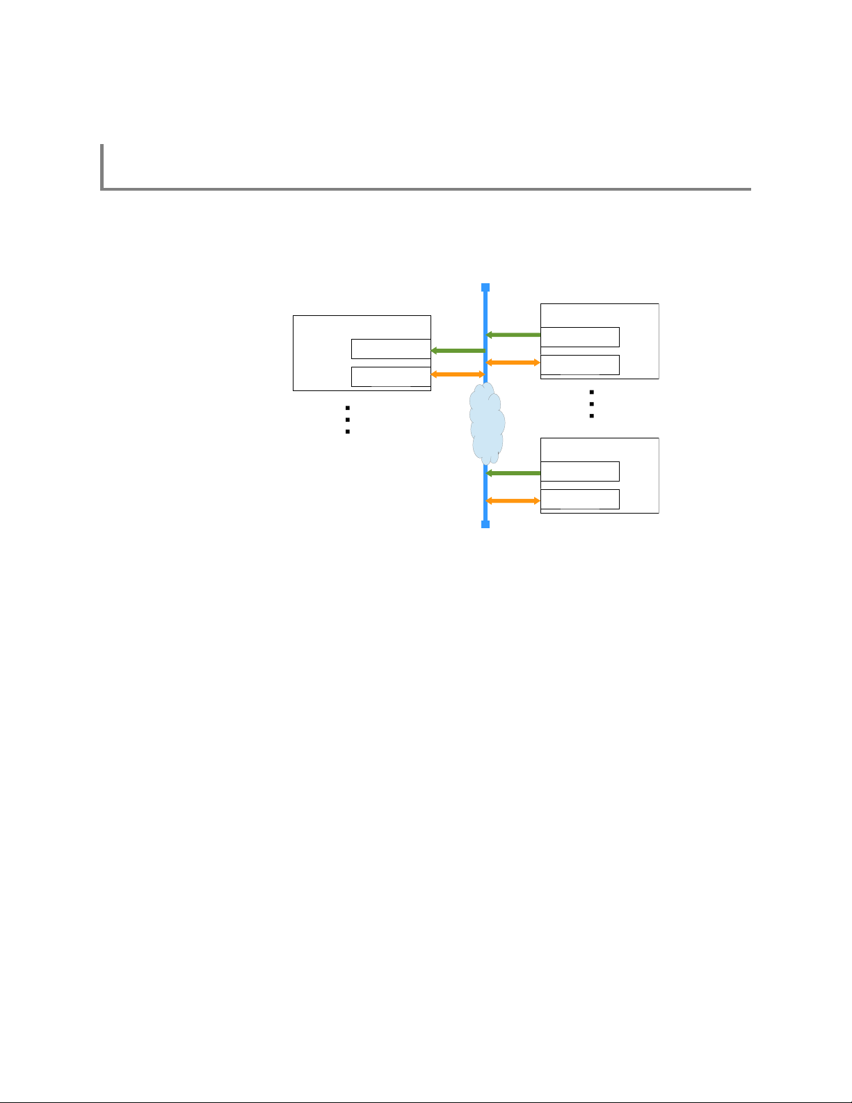
Appendix A: Connecting to RTSA
Network
Remote Host
<IP>:37000
<IP>:37001
RTSA
<IP>:37000
<IP>:37001
RTSA
<IP>:37000
<IP>:37001
SCPI
SCPI
SCPI
VRT pkts
VRT pkts
VRT pkts
Appendix A: Connecting to RTSA
ThinkRF's RTSAs are network ready devices conveying control commands and data
using TCP/IP protocol. Each RTSA receives SCPI commands and sends query
responds over port 37001, and sends VRT context and data packets over port 37000, as
illustrated in the following figure:
A RTSA, when powered up, will have a dynamic or preassigned static IP address, which
when bind with a port will form a network socket. To successfully establish a connection
to a RTSA, both <IP>:37000 and <IP>:37001 sockets must be created one right after the
other, the order is not important.
In addition, refer to the “Connecting to the R5500” of the R5500 User Guide (v4.0 or later)
for more information on how to connect to R5500 and to determine its IP address.
80 ThinkRF R5500 Real Time Spectrum Analyzer Programmer's Guide
Page 81

Appendix B: Protocol for Discovering RTSA
Appendix B: Protocol for Discovering RTSA
ThinkRF uses a simple broadcast UDP protocol for discovering any RTSAs available on
the same local network as the host computer. This protocol can not be used to find any
RTSAs on a different network.
The remote host computer would first send out a UDP message of broadcast type to port
18331. The message contains a query request code followed by query discovery version
in big-endian order as follows:
<request code><discovery version>
where each field is:
Name Data Type Length Required Value
request code 32-bit unsigned integer 1 0x93315555
discovery version 32-bit unsigned integer 1 2
The discovery version is used to determine how to parse the response message. Note
that the <> bracket is for clarity of the explanation purpose only, not to be included in the
message.
A RTSA with the discovery version 2 would respond with the following data:
<response code><discovery version><RTSA model><RTSA S/N><firmware version>
where each field is:
Name Data Type Length Response Value
response code 32-bit unsigned integer 1 0x93316666
discovery version 32-bit unsigned integer 1 2
RTSA model ASCII character, nul-padded 16 RXXXX-XXX (ex: R5500-427)
RTSA S/N ASCII character, nul-padded 16 XXXXXX-XXX (ex: 120600-020)
firmware version ASCII character, nul-padded 20 vX.X.X (ex: v1.0.0)
The IP address of a RTSA can be retrieved from the responding socket. The RTSA may
be identified by matching the serial number (S/N) in the response message with the S/N
on the label of the RTSA.
ThinkRF R5500 Real Time Spectrum Analyzer Programmer's Guide 81
Page 82

Appendix C: SCPI Command Syntax
:SENSE:FREQ:CENTER 2441500000 Hz
Root node
Level 1
Level 2
Single space separator
Parameter
Single space separator
Optional unit
Appendix C: SCPI Command Syntax
Each SCPI command consists of a root node, one or more lower level nodes, follow by
applicable parameters and separators:
Entering Commands
SCPI commands have both a long and short version, such as :SOURCE and :SOUR.
The SCPI interface responds to either version, but will not respond to variations of either
version. The interface does not differentiate between upper-case and lower-case letters
but only the long or short form of a command.
An example correct and incorrect SCPI entry format for :SOURce command:
Command Entry
Correct Entry :SOURCE :SOURce :source
:SOUR :sour
Incorrect Entry :SOU :SOURC
:sourc
Note: At the end of each SCPI command string, whether a single command or multiple
commands separated by semicolons “;”, a new line-feed or carriage return is required.
Example in C: “:FREQ:CENTER 2400 MHZ\n” or “FREQ:CENT 2400 MHZ;INP:ANT 1\n”.
82 ThinkRF R5500 Real Time Spectrum Analyzer Programmer's Guide
Page 83

Notation
Notation Description
: Links command keywords together
; Separates multiple commands entered together on a single program
single space Uses to separate a parameter from a command or unit from a parameter
, Uses to separate multiples parameters of a command
[] Uses to optionally enclose zero or more parameters
{.} or {.}* The enclosed item maybe included zero or more times
{.}+ The enclosed items occurs one or more times
{.|.|.} One and only one of the two or more enclosed items separated by | maybe
<> Uses to enclose required parameter descriptions
? Indicates query command, use where applicable
| Indicates “or” and is used to separate alternative parameter options
::= Means “is defined as”
Parameter types
Appendix C: SCPI Command Syntax
message
included
This section defines different SCPI parameter data type.
Parameter Type Description
<boolean> ON | OFF | 1 | 0
Boolean parameters are always returned as 1 or 0 in NR1 format by query
commands
<integer>
<int>
<NR1> Signed integer without a decimal point (implied radix point)
<NR2> Signed number with an explicit radix point
<NR3> Scaled explicit decimal point numeric value with and an exponent
<NRf> <NR1>|<NR2>|<NR3>
<NRr> Non-decimal numeric value such as hexadecimal, octal or binary
<char>
<character>
<string> ASCII string surrounded by single or double quotes
Unsigned integer of NR1 format
Ex: 1 or 3432
Ex: -25 or 0
Ex: -1.234 or 1.0 or 0.0
Ex: 2.73e+2 or 2.351e2
Character program data
Ex: MAXimum or MEDium
Ex: “This is an example”
ThinkRF R5500 Real Time Spectrum Analyzer Programmer's Guide 83
Page 84

Appendix C: SCPI Command Syntax
Default Units
Parameter Default Unit
frequency Hz
time s or ns where applicable
voltage V
absolute amplitude dBm
relative amplitude dB
Units other than the default may be specified. If units are not specified then the default
units apply. Note the following examples, which are all equivalent.
Example
is equivalent to
is equivalent to
is equivalent to
is equivalent to
:FREQ:CENTer 2441.5 MHz
:FREQ:CENTer 2441500000
:FREQ:CENTer 2441500000 Hz
:FREQ:CENTer 244150 kHz
:FREQ:CENTer 2441.5e6
84 ThinkRF R5500 Real Time Spectrum Analyzer Programmer's Guide
Page 85

Appendix D: SCPI Status and Event Registers
Appendix D: SCPI Status and Event Registers
The RTSA's SCPI interface has a status and event reporting system that enables the
user to handle device events. The interface conforms to IEEE Std 488.2-1987 and SCPI
1999.0. This section discusses these status registers, status register enable masks,
event queues and event handling.
Status Byte Register (SBR)
The SBR is used to determine the specific nature of the event or condition. It is read by
issuing a *STB? command. The contents of the SBR are clear by issuing either a *STB?
or *CLS command.
Bits in the SBR will be set only when the corresponding bits in the Service Request
Enable Register are set.
Bit Name Description
0 not used This bit is not used and is always 0.
1 not used This bit is not used and is always 0.
2 Error / Event Available
(EAV)
3 Questionable Register
Summary
4 Message Available
(MAV)
5 Standard Event Status
Bit (ESB)
6 Request Service Summary of the Request Service register.
7 Operation Register
Summary
This bit is set if there are any unread error or event in the
System Error queue. It is read using the
:SYSTem:ERRor[:NEXT]? query command.
This bit is not used and is always 0.
This bit is set if there is any unread data in the Output queue.
This bit is set if there is any unread or non-cleared data in the
Standard Event Status register.
Summary of the Operation Status register
Standard Event Status Register (ESR)
The ESR is used to determine the nature of the status and error conditions. It is read by
issuing a *ESR? command. The contents of the ESR are clear by issuing either a *ESR?
or *CLS command.
Bits in the ESR will be set only when the corresponding bits in the Standard Events
Status Enable Register are set.
Bit Name Description
0 Operation Complete
(OPC)
1 Request Control (RQC) This bit is not used and is always 0.
2 Query Error (QYE) Set to indicate that a query has been made for which no
85 ThinkRF R5500 Real Time Spectrum Analyzer Programmer's Guide
Set to indicate that all pending operations are complete and
the R5500 is ready to accept another command, or that query
results are available.
response is available.
Query errors have SCPI error codes from –499 to –400.
Page 86

Bit Name Description
3 Device Dependent Error
(DDE)
4 Execution Error (E) Set to indicate that a parameter exceeds its allowed range.
5 Command Error (CME) Set to indicate that a command error has occurred.
6 not used This bit is always 0.
7 Power ON (PON) Set once upon power-up. This bit has no effect on the Error /
Set to indicate that a device-dependent error has occurred.
Device-dependent errors have SCPI error codes from –399 to
–300 and 1 to 32767.
Execution errors have SCPI error codes from –299 to –200.
Command errors have SCPI error codes from –199 to –100.
Event Available (EAV) bit in the Status Byte Register.
Operational Status (OSR) Register
The OSR is a 16-bit register that is used to determine the state of operation. It is read by
issuing a :STATus:OPERation[:EVENt]? command.
Bit Name Description
0-3 not used These bits are not used and is always 0.
4 Measuring (MEAS) Set to indicate that a query has been made for which no
response is available.
Query errors have SCPI error codes from –499 to –400.
5-15 not used These bits are not used and is always 0.
Appendix D: SCPI Status and Event Registers
Output Queue
The R5500 has an Output FIFO Queue that is structured as a FIFO and holds the
response messages to queries. The SBR's MAV bit is set when there are messages in
the queue. The unread results of a previous command are cleared from the queue when
a new command or query is received.
Error and Event Queue
The R5500 has an Error and Event FIFO Queue that holds up to 16 errors and events. It
is queried using the :SYSTem:ERRor[:NEXT]? command. The *CLS command clears all
entries from the queue.
ThinkRF R5500 Real Time Spectrum Analyzer Programmer's Guide 86
Page 87

Appendix E: SCPI Error Codes Used
Appendix E: SCPI Error Codes Used
Code Message Description
0 No error
Command error, range [-199, -100]
-144 Character data too long The character data contained more than 12 characters.
-171 Invalid expression The command syntax was incorrect.
Execution error, range [-299, -200]
-200 Execution error A generic execution error for which more specific information is
not available.
-210 Trigger error
-220 No matched module The specific operation is not installed.
-221 Settings conflict Indicates that a legal program data element was parsed but
could not be executed due to the current device state
-222 Data out of range A parameter was of the proper type but outside of the defined
range for the specific command.
-223 Too much data A parameter was received that contained more data than the
device could handle.
-224 Illegal parameter value A parameter was received that is NOT allowed for the particular
command.
-230 Data corrupt or stale Possibly invalid data; new reading started but not completed
since last access.
-240 Hardware error Indicates that a legal program command or query could not be
executed because of a hardware problem in the device.
-241 Hardware missing Indicates that a legal program command or query could not be
executed because of missing device hardware. For example,
an option is not installed
Device specific error, range [-399, -300]
-310 System error
-321 Out of memory An internal operation needed more memory than that was
available.
-330 Self test failed
-340 Calibration failed
-350 Query overflow The SCPI remote interface error queue overflowed.
Query error, range [-499, -400]
-410 Query INTERRUPTED A condition causing an INTERRUPTED query error occurred
ThinkRF's RTSA Specific, range [-999, -900]
-901 No data Read trace command issued while there is no data available.
-911 Need firmware upgrade The current firmware needs upgrading.
-912 Invalid option license The option could not be installed because of invalid license.
87 ThinkRF R5500 Real Time Spectrum Analyzer Programmer's Guide
Page 88

Appendix F: SCPI Commands Quick Reference
Appendix F: SCPI Commands Quick Reference
This section summarizes the SCPI commands available for interfacing with R5500. The
commands are listed alphabetically based on the main node, then sub-nodes, so on. The
sub-nodes are grouped and listed alphabetically based on functionality.
See Appendix C's Notation section for details on notations used in the Parameter column.
The Release column indicates from which firmware release version that the commands
are available. Grayed-out commands are not yet implemented.
Keyword Parameter Description Release
IEEE Mandated
*CLS Clear all status registers v1.0
*ESE <integer> Event Status Enable register v1.0
*ESE? Query ESE register v1.0
*ESR? Query Event Status Register v1.0
*IDN? Query device identification v1.0
*OPC Operation Complete v1.0
*OPC? Query OC v1.0
*RST Reset to factory default v1.0
*SRE <integer> Service Request Enable bits v1.0
*SRE? Query SRE register v1.0
*STB? Query Status Byte register v1.0
*TST? Query self-test status v1.0
*WAI Wait-to-Continue v1.0
:INPut
:ATTenuator 0 | 10 | 20 | 30 Set the fix attenuation for R5500-308 and -408
:ATTenuator?
:VARiable 0 | 10 | 20 | 30 Set the variable attenuation for R5500-418 and
:VARiable?
:GAIN <index> <ON | OFF | 1 | 0>
:GAIN? <index>
:HDR Set gain level for the narrow-band ADC of the
:HDR? [MAX | MIN]
:MODE ZIF | DD | HDR | SH | SHN Select the receiver mode of operation.
:MODE?
Page 41
Page 59
models and their variants
-427 models and their variants
Set an input gain stage to be on or off. The index
range is model dependent.
HDR signal path
See the complete command description section
for special notes.
v1.0 – ZIF,
SH, SHN, DD
v1.3 – HDR
v1.0
v1.0
v1.0
v1.3
:OUTput
:MODE CONNector | DIGitizer | HIF Select the output path type v1.0 – CONN
:MODE?
Page 66
| DIG
ThinkRF R5500 Real Time Spectrum Analyzer Programmer's Guide 88
Page 89

Appendix F: SCPI Commands Quick Reference
Keyword Parameter Description Release
[:SENSe]
:DECimation OFF | <integer> Set the decimation rate as an exponent of 2 (i.e.
:DECimation? [MAX | MIN]
:FREQuency
:CENTer <NRf [unit]> Set the center frequency of the RFE v1.0
:CENTer? [MAX | MIN]
:IF? <non-zero integer> Query the IF frequencies that are used for the
:INVersion? [NRf [unit]] Query if spectral inversion is required at a given
:LOSCillator? <1 | 2 | 3> Get the frequency of the external LO 1, 2, or 3
:SHIFt <NRf [unit]> Set the frequency shift value (not available for
:SHIFt? [MAX | MIN] v1.0
:LOCK
:REFerence? Query the lock status of the PLL reference clock v1.0
:RF? Query the lock status of the RFE's RF PLL v1.0
:SOURce
:REFerence
:PLL INT | EXT
:PLL?
:RESET
Page 62
rate = 2
current input mode and center frequency
frequency
in corresponding to current the RTSA's center
frequency.
HDR mode)
Page 61
Select the 10MHz reference clock source
Reset the 10MHz reference selection to INTernal
source
level
where level = 0, 1, 2 - 10)
v1.0
v1.0
v1.0
v1.0
v1.0
v1.0
v1.0
:STATus
:OPERation Return the standard Operation Status Register
[:EVENt]? v1.0
:CONDition? TBD
:ENABle <integer> v1.0
:ENABle?
:PRESET Presets the R5500 (similar to *RST) TBD
:QUEStionable Return the standard Questionable Status
[:EVENt]? TBD
:CONDition? TBD
:ENABle <integer> v1.0
:ENABle?
:TEMPerature? Return the R5500's internal ambient
:SWEep
:LIST
:ITERations <integer> Define the number of times the list is repeated
Page 55
(OSR) for any event
Register (QSR) for any event
v1.0
temperature
Page 72
v1.0
during execution
89 ThinkRF R5500 Real Time Spectrum Analyzer Programmer's Guide
Page 90

Appendix F: SCPI Commands Quick Reference
Keyword Parameter Description Release
:ITERations?
:STARt [integer] Begin execution of the current sweep list from
the first entry
:STATus?
:STOP Stop execution of the current sweep list v1.0
:ENTRy
:COPY <integer> Copie the settings of an existing sweep entry
into the current settings for quick editing
:COUNt? Get the number of entries available in the list v1.0
:DELETE <integer> | ALL Delete a specified entry or all entries v1.0
:NEW Set the sweep entry's capture configuration
settings to default values
:READ? <integer> Get the settings of an existing sweep entry v1.0
:SAVE [integer] Save the current editing entry to the end of the
list or before the specified ID location in the list
when the integer value is given
:ATTenuator As defined in :INPut:ATTenuator, page 59 v1.0
:VAR[?] As defined in :INPut:ATTenuator:VARiable, page 59 v1.4
:DECimation As defined in [:SENSe]:DECimation, page 62 v1.0
:DECimation?
:FREQuency
:CENTer <NRf [unit]>[,<NRf [unit]>]
::= <start freq>[,<stop freq>]
:CENTer?
:SHIFt As defined in [:SENSe]:FREQuency:SHIFt, page 65 v1.0
:SHIFt? v1.0
:STEP <NRf [unit]> Set the amount of frequency that the center
:STEP?
:GAIN
:HDR As defined in :INPut:GAIN:HDR, page 60 v1.3
:HDR?
:MODE
:MODE?
As defined in :INPut:MODE, page 61
Set the center frequency or a range of center
frequencies that are stepped by the value
defined by :SWEep:ENTRy:FREQuency:STEP
frequency is stepped by
v1.0
v1.0
v1.0
v1.0
v1.0
v1.0
v1.0
v1.0
:DWELl <integer>[,<integer>]
::= <sec>[,<microsec>]
:DWELl?
:PPBlock Same as :TRACe:BLOCk:PACKets, page 70 v1.0
:PPBlock?
:SPPacket As defined in :TRACe:SPPacket, page 70 v1.0
:SPPacket?
:TRIGger
:LEVel As defined in :TRIGger:LEVel, page 67 v1.4
:LEVel?
Set the maximum amount of time to wait for the
trigger of a sweep entry to occur, after which the
trigger is aborted and the next sweep entry if
existed will run. When the trigger type is NONE,
dwell time is ignored. Default 0.0 sec.
v1.0
ThinkRF R5500 Real Time Spectrum Analyzer Programmer's Guide 90
Page 91

Appendix F: SCPI Commands Quick Reference
Keyword Parameter Description Release
:TYPE As defined in :TRIGger:TYPE, page 67 v1.0 – PULSE
:TYPE?
:SYSTem
:ABORt Abort the current data capturing process and
:CAPTure
:MODE? Get the current capture mode of the RTSA (i.e.
:COMMunicate
:LAN
:APPLy Apply the new RTSA's LAN settings from the
:CONFigure DHCP | STATIC Set the RTSA's LAN to use DHCP or STATIC
:CONFigure? [CURRENT] v1.0
:DNS <main DNS>[,alt DNS] Set the RTSA's LAN DNS address(es) v1.0
:DNS? [CURRENT]
:GATEway <IPv4 address> Set the RTSA's LAN Gateway address v1.0
:GATEway? [CURRENT]
:IP <IPv4 address> Set the new IPv4 address for the RTSA's LAN v1.0
:IP? [CURRENT]
:MTU <MTU value> Set the MTU value between 256 and 1500,
:MTU? [CURRENT]
:NETMask <IPv4 address> Set the RTSA's LAN netmask address v1.0
:NETMask? [CURRENT]
:NTP <IPv4 address> Set an NTP IP serve address for time updating
:ERRor v1.0
[:NEXT]? Return the SCPI error/event queue v1.0
:FLUSh Clear the R5500's internal data storage buffer of
:LOCK
:HAVE? ACQuisition Return the current lock state of the task
:REQuest? ACQuisition Request the R5500 to provide a lock on a
:OPTions? Returns comma separated 3-digit values to
:SYNC
:MASTer ON | OFF | 1 | 0 Set a RTSA unit to be the master or slave for a
Page 44
puts the RTSA system into a normal manual
mode (i.e. sweep, trigger, and streaming will be
aborted)
sweeping, streaming or block mode)
commands above, which will then take effect.
This command should be applied only once all
the required LAN settings have been set.
configuration type
inclusive
any remaining old data that has not been
transferred out of the RTSA.
specified
specific task such that only the application that
has the lock can perform the task
represent the hardware option(s) or features
available with a particular RTSA model
synchronization trigger system with multiple
units. Affects :TRIG:TYPE PULSe or WORD
| WORD |
NONE
v1.4 – LEVel
| PPS
v1.0
v1.0
v1.0
v1.0
v1.4.6
v1.0
v1.0
v1.0
v1.0
v1.0
91 ThinkRF R5500 Real Time Spectrum Analyzer Programmer's Guide
Page 92

Appendix F: SCPI Commands Quick Reference
Keyword Parameter Description Release
:MASTer?
:WAIT <integer> Set the delay time in nanoseconds that the
system must wait after receiving the trigger
signal before performing data capture
:WAIT?
:VERSion? Return the SCPI compliance version v1.0
v1.0
:DATE <integer>,<integer>,<integer>
::= <year>,<month>,<date>
:DATE? Get the date in the box v1.0
:TIME <integer>,<integer>,<integer>
[,<integer>] | <char>
::= <hr>,<min>,<s>[,<ms>]
:TIME? Returns <hr>,<min>,<s> in UTC time v1.0
:ADJust
:SYNC
:SYNC? v1.4
:STATus? Return the status of the time synchronization
<integer>
DISable | NTP,{ONCE |
CONTinuous}
:TRACe
:BLOCk
:DATA? Initiate the sending of the IQ data captured v1.0
:PACKets <integer> Set the number of IQ data packets to be
:PACKets? [MAX | MIN]
:SPPacket <integer> Define the number of IQ samples per VRT
:SPPacket? [MAX | MIN]
:STReam
:STARt [integer] Initiate the capture, storage and streaming of IQ
:STOP Stop streaming v1.0
Set the date v1.4
Set the time v1.4
Adjust the system time relative to it's current
time
Select the synchronization source and mode v1.4
Page 68
v1.0
captured per block (a block = :PACKets * SPP)
v1.0
packet, and must be a multiple of 16
v1.0
data
:TRIGger
:LEVel <NRf [unit]>,<NRf[unit]>,<NRf
[unit]>
::= <start>,<stop>,<level>
:LEVel?
:PERiodic <integer [unit]> Set the time period of a periodic trigger TBD
:PERiodic?
:TYPE LEVel | PERiodic | PPS |
PULSe | WORD | NONE
:TYPE?
Page 67
Set the frequency range and amplitude of a
frequency domain level trigger
Set or disables the trigger type v1.0 – PULSE
v1.4
| WORD |
NONE
v1.4 – LEVel |
PPS
ThinkRF R5500 Real Time Spectrum Analyzer Programmer's Guide 92
Page 93

WSA5000 vs. R5500 List of Changes
WSA5000 vs. R5500 List of Changes
This section provides a list of changes in the R5500's Programmer's Guide as compare
to that of the WSA5000.
Sections R5500
Functional
Overview
SCPI Commands
:INPut Modified the following commands:
:OUTput Removed
Updated the Architecture and RF Receiver Front-end sections to reflect the
new capabilities with new hardware changes (see Figure 1 and Figure 2)
The ADC used is of 14-bit channel. See Table 2: Radio RFE Modes and DSP
Data Output Formats page 16 for changes to the notes.
Removed the IQ offset correction algorithm in the IQ Offset Correction section
as the correction is made available in an API function.
Remove all mentioning of IQIN option and -408P model as they are not
available with R5500 models.
+ :INPut:ATTenuator's parameters are 0 | 10 | 20 | 30 in dB, not ON | OFF | 1
| 0 for 20 or 0 dB, respectively.
+ :INPut:ATTenuator:VARiable's parameters are 0 | 10 | 20 | 30 in dB, not 0 –
25 dB
+ :INPut:MODE no longer has HIF and IQIN option. The HIF option is now in
:OUTput:MODE as HIF is made available in all R5500 models, and the IQIN
option is no longer supported.
+ :GAIN – Change in the gain stage 'index' values for different models
+ :IQ node
+ :OUTput:CONNector:INVersion and replace with
[:SENSe]:FREQuency:INVersion?
Added HIF option for :OUTput:MODE
[:SENSe] Added [:SENSe]:FREQuency:INVersion? command
:SYSTem :SYSTem:OPTions? no longer returns code for ELO and HIF. ELO is no
longer supported in R5500 models. HIF is made available in all R5500
models, and is now control through the :OUTput:MODE command.
Added :SYSTem:COMMunicate:LAN:MTU command
93 ThinkRF R5500 Real Time Spectrum Analyzer Programmer's Guide
Page 94

References
1. “Standard Commands for Programmable Instruments (SCPI)”, SCPI Consortium, May
1999, version 1999.0, http://www.spiconsortium.org
2. "VITA Radio Transport (VRT) Draft Standard" VITA-49.0 – 2007, VITA Standard
Organization, 31 October 2007, Draft 0.21, http://www.vita.com/
3. "IEEE Standard Codes, Formats, Protocols, and Common Commands", ANSI/IEEE
Standard 488.2-1992, http://ieeexplore.ieee.org/xpl/freeabs_all.jsp?
tp=&isnumber=5581&arnumber=213762&punumber=2839
References
ThinkRF R5500 Real Time Spectrum Analyzer Programmer's Guide 94
Page 95

Document Revision History
Document Revision History
This section summarizes document revision history.
Document
Version
v4.0.0 Mar 01, 2017 First release of this document, basing on WSA5000's Programmer's
v4.0.1 Mar 15, 2017 - Updated information in the Obtaining Technical Assistance section
v4.1.0 Mar 31, 2017 - Enabled :SYSTem:DATE, :SYSTem:TIME, and
v4.1.1 April 10, 2017 - Updated “Allowable Values” for :INPut:GAIN command and added
v4.1.2 April 24, 2017 - Updated details on the level trigger and added to :TRIGger:LEVel
v4.1.3 July 4, 2017 - Removed mentioning of the WBIQ models with decimation, as these
v4.1.4 July 24, 2017 - Update the Sample Loss Indicator definition
v4.2.0 Aug 28, 2017 - Added :SYSTem:COMMunicate:LAN:MTU command to change the
Release Date Revisions and Notes
1
Guide. See WSA5000 vs. R5500 List of Changes for a summary of
main changes.
- Corrected the description for [:SENSe]:FREQuency:LOSCillator?
command
:SYSTem:TIME:SYNC, and added :SYSTem:COMMunicate:NTP
commands used for updating or correcting an R5500's date and/or
time
- Added PPS type to :TRIGger:TYPE
Table 37
- Added a note to :INPut:ATTenuator:VARiable command to
recommend using 0 dB attenuation for best performance
the upper trigger threshold limits which depend on the input
attenuation set
- Corrected the IP ports in the diagram of Appendix A: Connecting to
RTSA
models work with external digitizer for ZIF & SH modes
maximum network packet or frame size in a transaction
- Corrected information regarding the behaviour of the sweep engine
when the internal buffer becomes full, see SWEep Commands section
1
Document Version is not the same as the firmware Release Version as mentioned in
Appendix F: SCPI Commands Quick Reference.
95 ThinkRF R5500 Real Time Spectrum Analyzer Programmer's Guide
 Loading...