

Page 1

D2030
30 GHz Downconverter
Programmer's Guide
Version 1.2.1
Mar 2018
Document no. 75-0070-180301
Copyright © 2017,2018 ThinkRF Corporation, all rights reserved.
All product names are trademarks of their respective companies.
This document contains information that is proprietary to ThinkRF Corporation.
Page 2

Important notice
The information in this
guide is furnished for
informational use only
and is subject to change
without notice. ThinkRF
Corporation assumes no
responsibility or liability
for any errors or
inaccuracies that may
appear in this document.
No part of this
publication may be
reproduced, published,
stored in an electronic
database, or transmitted,
in any form or by any
means, electronic,
mechanical, recording,
or otherwise, for any
purpose, without the
prior written permission
of ThinkRF Corporation.
Trademarks
ThinkRF, the ThinkRF
logo and D2030 are
trademarks of ThinkRF
Corporation.
All other brand or
product names are
trademarks or registered
trademarks of their
respective companies or
owners.
ThinkRF Corp
390 March Road
Kanata, ON K2K 0G7
(613) 369-5104
HARDWARE WARRANTY AND LIMITATION OF LIABILITY
Read this warranty carefully before you use the product.
D2030 30 GHz Downconverters are warranted for workmanship and materials for a
period of one (1) year from the date of shipment as identified by the Customer’s
packing slip or carrier waybill. ThinkRF reserves the right to void the warranty on any
equipment that has been altered or damaged due to Customer negligence,
unauthorized repair, misuse of equipment, evidence of physical or environmental
damage, transportation abuse or removal of any ThinkRF identification labels or
serial numbers.
It will remain the responsibility of the Customer, having obtained a Return Material
Authorization (RMA) and shipping instructions from ThinkRF, to return, at the
Customer's expense, the defective unit to ThinkRF’s repair facilities. ThinkRF will
incur shipping charges for the return of warranty repaired equipment. The RMA
number can be secured by calling ThinkRF Customer Service and Support (1-613369-5104). If the product does not fall within ThinkRF’s warranty period or the
product is found to be functioning as designed, then under the terms of ThinkRF’s
warranty policy, all costs of repairs and shipping will be charged directly to the
Customer. ThinkRF will warrant repaired units for a period of 90 days from date of
shipment from ThinkRF to the Customer. If the remaining period on the original
hardware warranty is greater than 30 days, then ThinkRF will honor this remaining
warranty period.
THINKRF EXPRESSLY DISCLAIMS ALL OTHER WARRANTIES AND
CONDITIONS, WHETHER EXPRESS OR IMPLIED, INCLUDING WITHOUT
LIMITATION, WARRANTIES, CONDITIONS OR REPRESENTATIONS OF
WORKMANSHIP, MERCHANTABILITY, FITNESS FOR A PARTICULAR
PURPOSE, DURABILITY, OR THAT THE OPERATION OF THE HARDWARE OR
LICENSED SOFTWARE WILL BE ERROR FREE. IN NO EVENT WILL THINKRF
BE LIABLE FOR INDIRECT, SPECIAL, INCIDENTAL, OR CONSEQUENTIAL
DAMAGES.
USE OF PRODUCTS IN HIGH RISK ACTIVITIES
THINKRF PRODUCTS ARE INTENDED FOR STANDARD INDOOR COMMERCIAL
USE. WITHOUT THE APPROPRIATE NETWORK DESIGN ENGINEERING, THEY
MUST NOT BE USED FOR ANY “HIGH RISK ACTIVITY”, as described in this
paragraph. Customer acknowledges and agrees that the products supplied
hereunder are not fault-tolerant and are not designed, manufactured or intended for
use or resale as on-line control equipment in hazardous environments requiring fail
safe performance including but not limited to the operation of nuclear facilities,
aircraft navigation or communication systems, air traffic control, direct life support
machines, or weapons systems, in which the failure of products could lead directly to
death, personal injury, or severe physical or environmental damage, all of which are
examples of “High Risk Activity”. THINKRF AND ITS SUPPLIERS EXPRESSLY
DISCLAIM ANY EXPRESS OR IMPLIED WARRANTY OF FITNESS FOR HIGH
RISK ACTIVITIES.
Page 3

Table of Contents
Abbreviations ................................................................................................................................... 5
List of Figures .................................................................................................................................. 6
List of Tables .................................................................................................................................... 6
Preface ................................................................................................................................................. 7
Audience .................................................................................................................................... 7
Conventions .............................................................................................................................. 7
Obtaining Documentation and Releases ............................................................................ 8
Document Feedback ................................................................................................................ 8
Obtaining Technical Assistance ........................................................................................... 8
D2030 Functional Overview ...................................................................................................... 9
System Overview ...................................................................................................................... 9
RF Receiver Front-End .......................................................................................................... 10
SCPI Command Set ..................................................................................................................... 12
SCPI Language Overview ..................................................................................................... 12
IEEE Mandated SCPI Commands ....................................................................................... 13
*CLS .................................................................................................................................... 13
*ESE/*ESE? ........................................................................................................................ 13
*ESR? .................................................................................................................................. 13
*IDN? ................................................................................................................................... 14
*OPC/*OPC? ....................................................................................................................... 14
*RST .................................................................................................................................... 14
*SRE/*SRE? ........................................................................................................................ 15
*STB? .................................................................................................................................. 15
*TST? .................................................................................................................................. 15
*WAI .................................................................................................................................... 16
SYSTem Commands .............................................................................................................. 16
:SYSTem:COMMunicate:LAN:APPLy .................................................................................. 16
:SYSTem:COMMunicate:LAN:CONFigure .......................................................................... 16
:SYSTem:COMMunicate:LAN:GATEway ............................................................................ 17
:SYSTem:COMMunicate:LAN:IP ......................................................................................... 17
:SYSTem:COMMunicate:LAN:NETMask ............................................................................. 18
:SYSTem:ERRor[:NEXT]? ................................................................................................... 18
:SYSTem:ERRor:ALL? ........................................................................................................ 19
:SYSTem:OPTions? ............................................................................................................ 19
:SYSTem:VERSion? ............................................................................................................ 19
STATus Commands ............................................................................................................... 20
Status Reporting Structures ................................................................................................. 20
:STATus:OPERation[:EVENt]? ............................................................................................ 23
:STATus:OPERation:CONDition? ........................................................................................ 23
:STATus:OPERation:ENABle .............................................................................................. 24
:STATus:OPERation:NTRansition ....................................................................................... 24
:STATus:OPERation:PTRansition ....................................................................................... 24
:STATus:PRESET ............................................................................................................... 25
Page 4

:STATus:QUEStionable[:EVENt]? ....................................................................................... 25
:STATus:QUEStionable:CONDition? ................................................................................... 25
:STATus:QUEStionable:ENABle .......................................................................................... 26
:STATus:QUEStionable:NTRansition .................................................................................. 26
:STATus:QUEStionable:PTRansition ................................................................................... 26
:STATus:TEMPerature? ...................................................................................................... 27
INPut Commands ................................................................................................................... 27
:INPut:DCONverter:MANual:FILTer:PRESelect .................................................................. 27
:INPut:GAIN ......................................................................................................................... 27
SENSe Commands ................................................................................................................. 28
[:SENSe]:DCONverter:MANual:LO<1|2>:FREQuency ........................................................ 28
[:SENSe]:DCONverter:MANual:MIX2 .................................................................................. 28
[:SENSe]:FREQuency:CENTer ........................................................................................... 28
[:SENSe]:REFerence:PLL ................................................................................................... 29
OUTPut Commands ............................................................................................................... 29
:OUTPut:DCONverter:MANual:ATTenuation ....................................................................... 29
:OUTPut:FILTer:BPASs:BANDwidth? .................................................................................. 30
:OUTPut:FILTer:BPASs:FREQuency? ................................................................................ 30
:OUTPut:IF:FREQuency? .................................................................................................... 30
Appendix A: Booting up and Connecting to the D2030 .......................................... 31
Bootup Sequence ................................................................................................................... 31
Connecting to D2030 ............................................................................................................. 31
SCPI Raw ............................................................................................................................ 31
SCPI Telnet ......................................................................................................................... 32
HiSLIP ................................................................................................................................. 32
Code Example of TCP/IP Connection and SCPI Control .............................................. 33
Appendix B: SCPI Command Syntax ................................................................................ 40
Entering Commands .............................................................................................................. 40
Notation .................................................................................................................................... 41
Parameter types ...................................................................................................................... 41
Default Units ............................................................................................................................ 42
Appendix C: SCPI Status and Event Registers ........................................................... 43
Status Byte Register (SBR) .................................................................................................. 43
Standard Event Status Register (ESR) .............................................................................. 43
Operational Status (OSR) Register .................................................................................... 44
Questionable Status (QSR) Register ................................................................................. 44
Output Queue .......................................................................................................................... 45
Error and Event Queue ......................................................................................................... 45
Appendix D: SCPI Error Codes Used ................................................................................ 46
Appendix E: SCPI Commands Quick Reference ........................................................ 47
References ....................................................................................................................................... 50
Document Revision History ................................................................................................... 51
Page 5

Abbreviations
Abbreviations
ADC Analog-to-Digital Converter
API Application Programming Interface
HiSLIP Hi Speed LAN Instrument Protocol
IEEE Institute of Electrical and Electronics Engineers
IF Intermediate Frequency
LAN Local Area Network
MSB Most Significant Byte
PLL Phase-Locked Loop
RF Radio Frequency
RFE Receiver Front-End
Downconverter 30 GHz Downconverter
SCPI Standard Commands for Programmable Instruments
TCP/IP Transmission Control Protocol/Internet Protocol
5 ThinkRF D2030 30 GHz Downconverter Programmer's Guide
Page 6

Abbreviations
List of Figures
Figure 1: D2030 Interconnect Diagram with A Spectrum Analyzer ............................................................ 9
Figure 2: SCPI Language Hierarchical or Tree Structure Example .......................................................... 12
Figure 3: SCPI Downconverter Instrument Model .................................................................................... 13
Figure 4: Status Reporting Structure with Status & Enable Registers ...................................................... 21
Figure 5: SDS Register Model ................................................................................................................. 22
List of Tables
Table 1: System Level Control/Status Commands ................................................................................... 10
Table 2: RF Front-End Control/Status Commands .................................................................................. 11
Table 3: Downconverter Option Codes and the Corresponding Description ............................................ 19
ThinkRF D2030 30 GHz Downconverter Programmer's Guide 6
Page 7

Preface
Preface
This preface describes the audience for, the organization of, and conventions used in this
document. It also identifies related documentation and explains how to access electronic
documentation.
Audience
This document is written for software developers wishing to develop and/or maintain a
software interface to the D2030 and who have a basic understanding, familiarity and
experience with network test and measurement equipment.
Conventions
This section describes the conventions used in this document.
Grayed-out Font
Indicates a command or a feature is not yet available in the current release.
Courier Font
Illustrates this is an example for a command or a concept.
Light Blue Font
Contains hyperlink to the referenced source that can be clicked on.
Normal Bold Font
When used within a sentence or a paragraph, it emphasizes an idea to be paid attention
to particularly.
Red Font
Conveys special information of that section.
Note: This symbol means take note. Notes contain helpful suggestions or references to
additional information and material.
Caution: This symbol means be careful. In this situation, you might do something that
could result in equipment damage or loss of data.
Warning: This symbol means danger. You are in a situation that could cause bodily
injury. Before you work on any equipment, be aware of the hazards involved with
electrical circuitry and be familiar with the standard practices for preventing accidents.
7 ThinkRF D2030 30 GHz Downconverter Programmer's Guide
Page 8

Obtaining Documentation and Releases
You can access the most current ThinkRF documentation and the latest release bundles
at http://www.thinkrf.com/resources.
Document Feedback
Please send your comments about this document or our other documentation to
support@thinkrf.com.
Thank you, we appreciate your comments.
Obtaining Technical Assistance
The ThinkRF Support website provides online documents for resolving technical issues
with ThinkRF products at http://www.thinkrf.com/resources.
For all customers who hold a valid end-user license, ThinkRF provides technical
assistance 9 AM to 5 PM Eastern Time, Monday to Friday. Contact us at
support@thinkrf.com or by calling +1.613.369.5104.
Before contacting Support, please have the following information available:
Preface
• D2030's serial number which is located on the identification label on the D2030's
underside.
• The product version.
• The firmware version running on the D2030 (using *IDN? command).
• Versions of any ThinkRF software you are using.
• The operating system and version you are using.
ThinkRF D2030 30 GHz Downconverter Programmer's Guide 8
Page 9
D2030 Functional Overview
This section overviews the D2030's functionality and protocols used, and summarizes the
SCPI command sets for controlling the individual functions.
Note: This is a living and evolving document. We welcome your feedback.
The features and functionality described in this section may exist in the current product
firmware release or are scheduled for a future product firmware release (grayed out
commands and/or text). Please refer to Appendix E: SCPI Commands Quick Reference
for the complete list of commands and the availability information. No hardware upgrade
is required at each feature release (unless specified though unlikely).
System Overview
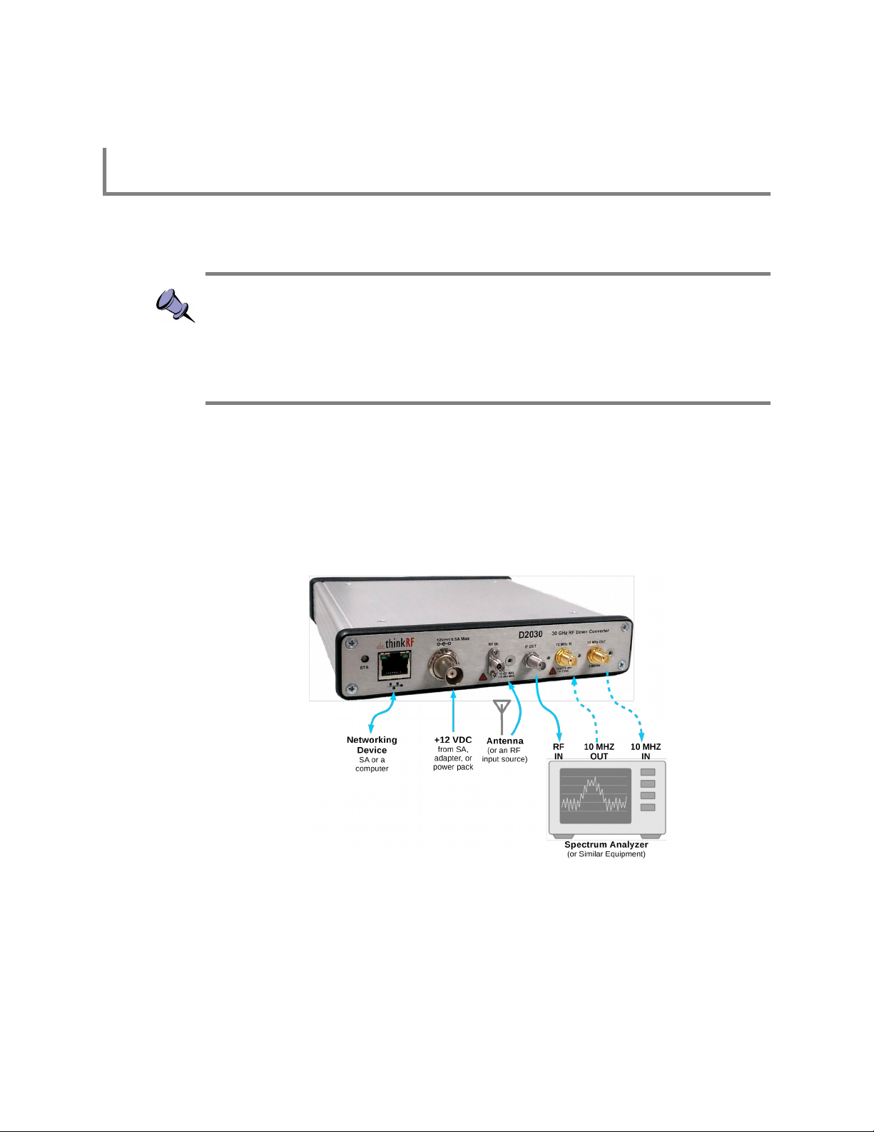
D2030 30 GHz Downconverter is used to convert RF signals in the range of 27-30 GHz
down to an intermediate frequency (IF) of 3.55 GHz or 5.6 GHz (determined by the
product Option code, see :SYSTem:OPTions?). This is designed to extend the
functionality of existing spectrum analyzers that operate to a maximum frequency of 4
GHz or 6 GHz, respectively, to measure and analyze 5G signals in the range of 27-30
GHz band. Figure 1 shows a simplify interconnect diagram with a spectrum analyzer.
D2030 Functional Overview
Figure 1: D2030 Interconnect Diagram with A Spectrum Analyzer
ThinkRF's products conform with standardized protocols for interoperability. Standard
protocols include the Standard Commands for Programmable Instruments (SCPI)
protocol for controlling and obtaining status from the Downconverter.
Refer to Appendix A for how to connect to a Downconverter.
The D2030 provides system level control and status commands as defined in Table 1.
ThinkRF D2030 30 GHz Downconverter Programmer's Guide 9
Page 10

D2030 Functional Overview
Table 1: System Level Control/Status Commands
SCPI Command Description
:SYSTem Page 16
:COMMunicate
:LAN<commands> Subset of commands for configuring/querying Downconverter's LAN
:ERRor Returns the error code and messages from the SCPI error/event queue
[:NEXT]?
:OPTions? Returns comma separated 3-digit values to represent the hardware
:VERSion? Returns the SCPI version number that the instrument complies with
:STATus Page 20
:OPERation
[:EVENt]? Returns the standard Operation Status Register (OSR) and clears the
:CONDition? Returns the standard Operation Condition Register (OCR)
:ENABle[?] Sets or queries the Operation Status Enable Register (OSE)
:PRESET Presets the D2030 (similar to *RST)
:QUEStionable
[:EVENt]? Returns the Questionable Status Register (QSR) and clears the register
:CONDition? Returns the Questionable Condition Register (QCR)
:ENABle[?] Sets or queries the Questionable Status Enable Register (QSE)
:TEMPerature? Returns the D2030's internal ambient temperature
settings
option(s) or features available with a particular Downconverter model
register
See SCPI Command Set section (page 12 onward) for further details on the commands.
Caution pertaining to multi-user: The current firmware version of the D2030 allows
multiple applications to connect to the unit simultaneously but it does not support
independent sessions. Therefore, the actions of one user may over-write those of
another. This could potentially damage the unit for instance if the front-end's gain were
incorrectly set. If multiple applications are connecting to the unit, it is advised that only
one of those is controlling the unit at any time.
RF Receiver Front-End
The receive front-end (RFE) has been largely defined through the hardware
specifications. The primary commands have to do with setting the center frequency of the
Downconverter and switching in the front-end gain for improved noise figure, ThinkRF
provides the user access to other blocks within the radio receiver. The command set is
defined in Table 2.
10 ThinkRF D2030 30 GHz Downconverter Programmer's Guide
Page 11

Table 2: RF Front-End Control/Status Commands
SCPI Command Description
:INPut Page 27
:DCONverter
:MANual
:FILTer
:PRESelect[?] Select or query the input preselect filter
:GAIN[?]
Set or query an input gain stage to be on or off.
[:SENSe] Page 28
:DCONverter
:MANual
:LO<1|2>
:FREQuency[?] Queries or manually sets the LO frequencies (LO1, LO2)
:FREQuency
:CENTer[?] Sets the center frequency of the D2030 RF input
:REFerence
:PLL[?] Selects the 10 MHz reference clock source
:OUTPut Page 29
:DCONverter
:MANual
:ATTenuation[?] Queries or sets the IF output attenuation in dB
:FILTer
:BPASs
:FREQuency? Queries the output filter bandpass frequency
:BANDwidth? Queries the output filter bandpass bandwidth
:IF
:FREQuency? Queries the output IF frequency
D2030 Functional Overview
See SCPI Command Set section (page 12 onward) for further details on each set of
commands.
ThinkRF D2030 30 GHz Downconverter Programmer's Guide 11
Page 12

SCPI Command Set
FREQuency DCONverter REFerence
SENSe
SCPI Command Set
This section is a SCPI reference guide for controlling the ThinkRF D2030 30 GHz
Downconverter. The D2030 supports the Standard Commands for Programmable
Instruments (SCPI) standard version 1999.0 as described in the following sections. SCPI
lends itself to a command line interface and scripting, is supported by the major
instrument vendors and provides a high level of familiarity for instrument users.
Note: The D2030 receives SCPI commands and sends query responses using one of
two network interfaces. It is accessible via telnet on port 5024, raw socket on port 5025,
or through a HiSLIP connection on port 4880. Certain features such as service requests
and equipment locking are only available with HiSLIP. See Appendix A: Booting up and
Connecting to the D2030 for more details.
SCPI Language Overview
In the early 1990s, a group of instrument manufacturers developed Standard Commands
for Programmable Instrumentation (SCPI) for controlling programmable instruments via a
communication link, such as RS232, USB, LAN, etc. SCPI specifies the command
structure and syntax using ASCII characters to provide some basic standardization and
consistency to the control commands. SCPI commands, hence, lend themselves to
communications with equipments via command line interface, scripting and/or
programming languages such as C/C++, MATLAB®, Python, etc.
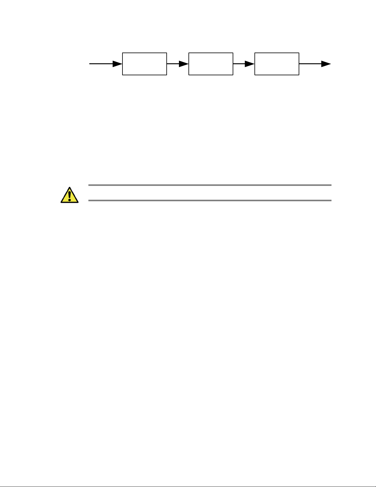
The SCPI language is based on a hierarchical or tree structure as illustrated in Figure 2
an example command set. The top level of the tree is the root node, which is followed by
one or more lower-level nodes.
Figure 2: SCPI Language Hierarchical or Tree Structure Example
The traditional model of a typical SCPI instrument involves either a measurement
function where an external input is digitized and processed, or a source function where a
signal is generated and sent to an external output. The D2030 does not fit this traditional
model in that it performs no intermediary digital processing. However, it performs tasks
such as frequency conversion purely in the analog domain. Figure 3 shows the D2030
simplified instrument model.
12 ThinkRF D2030 30 GHz Downconverter Programmer's Guide
Page 13
INPut SENSeINPut
Downconverter
Function
OUTPut
Figure 3: SCPI Downconverter Instrument Model
Refer to the Appendix B: SCPI Command Syntax section for the general SCPI command
syntax format and usage details.
IEEE Mandated SCPI Commands
These commands control and query the communication event/error and status registers
as defined in the Appendix C: SCPI Status and Event Registers section. They are
mandated by the IEEE.
Caution: The mandated IEEE SCPI commands are not affected by *RST command.
*CLS
SCPI Command Set
The Clear Status (CLS) command clears all the event status registers in the device
status-reporting mechanism and the error/event queue. This also results in the
corresponding summary bits in the Status Byte (STB) to be cleared.
Syntax *CLS
Parameter/Response None
*ESE/*ESE?
*ESE command sets bits in the ESE register. The decimal integer value entered is the
binary equivalent of the desired 8-bit mask. Bits set in the ESE enables the
corresponding bit in the ESR to assert the Standard ESR summary bit in the STB (bit 5).
*ESE? query returns the decimal sum of the bits in the ESE register.
See Figure 4 for the ESE/ESR register bit mapping.
Syntax *ESE <integer>
*ESE?
Parameter/Response <integer>
Allowable Values 0 - 255
*ESR?
Query the standard Event Status Register (ESR), which returns the decimal sum of the
bits in the ESR. The ESR will only appear set if and only if its event has occurred and the
corresponding bit in the ESE is also enabled.
ThinkRF D2030 30 GHz Downconverter Programmer's Guide 13
Page 14

SCPI Command Set
See Figure 4 for the ESR register bits mapping.
Caution: This is a destructive read. Once queried, the register is cleared.
*IDN?
Returns the D2030's identification information string.
Note: The model string returned will not include the options. To find out which options a
model has, use :SYSTem:OPTions? command.
Syntax *ESR?
Parameter None
Response <integer>
Description Refer to the Appendix C: SCPI Status and Event Registers section
for the ESR register bit definition
Syntax *IDN?
Parameter None
Response “<Manufacturer>,<Model>,<Serial number>,<Firmware version>”
Data Type string
*OPC/*OPC?
The *OPC/*OPC? commands allow synchronization between the controller and the
D2030.
*OPC (Operation Complete) sets bit 0 in the ESR to 1 when all commands received
before *OPC or *OPC? have been completed. When the D2030 is connected using a
HiSLIP session, this command can be used to raise a Service Request by configuring the
ESE and SRE registers appropriately.
*OPC? returns the ASCII character 1 in the Standard Event register indicating completion
of all pending operations. The query also stops any new commands from being
processed until the current processing is complete.
Syntax *OPC
*OPC?
Parameter None
Query Response 1
*RST
Resets the D2030 to its default settings.
14 ThinkRF D2030 30 GHz Downconverter Programmer's Guide
Page 15

SCPI Command Set
*RST does not affect the registers or queues associated with the IEEE mandated
commands. Each non-IEEE mandated command description in this reference shows the
*RST value when affected.
Syntax *RST
Parameter/Response None
*SRE/*SRE?
The *SRE (Service Request Enable) command enables bits in the SRE register. The
decimal integer value entered is the binary equivalent of the desired 8-bit mask. When a
bit is set in the SRE register and the corresponding STB register bit is also set, a Service
Request is raised if the D2030 is connected using a HiSLIP session. It has no effect
when connected via Telnet.
*SRE? query returns the decimal sum of the enabled bits in the SRE register. The
decimal sum is the binary equivalent of the 8-bit mask.
See Figure 4 for the SRE/STB register bit mapping.
Syntax *SRE <integer>
*SRE?
Parameter/Response <integer>
*STB?
*STB? (Status Byte) query returns the decimal sum of the bits set in the STB register
without erasing its content. Each bit corresponds to the underlying Status Data Structure.
See Figure 4 for the ESE/ESR register bits mapping and the Status Byte Register (SBR)
section of the Appendix C for the bit definitions.
Syntax *STB?
Parameter None
Response <integer>
*TST?
*TST? (self-test) query initiates the device's internal self-test and returns one of the
following results:
• 0 - all tests passed.
• 1 - one or more tests failed.
Syntax *TST?
Parameter None
Response 0 | 1
Output Data Type Integer
ThinkRF D2030 30 GHz Downconverter Programmer's Guide 15
Page 16

SCPI Command Set
*WAI
*WAI (Wait-to-Continue) command suspends the execution of any further commands or
queries until all operations for pending commands are completed.
Parameter/Response None
SYSTem Commands
These commands control and query the communication event and status registers as
defined in the Appendix C: SCPI Status and Event Registers. They are the minimal
:SYSTem sets required in all SCPI instruments.
:SYSTem:COMMunicate:LAN:APPLy
This command will save the changes to the LAN settings to the unit’s internal memory.
The new settings will take effect only after the D2030 has been rebooted or power
cycle. Once the LAN settings are saved, they are not affected by :STATus:PRESET or
*RST.
Syntax *WAI
Caution: When changing from DHCP to STATIC mode, this command should to be sent
only when all the required LAN settings are set using the appropriate subsequent
:SYSTem:COMMunicate:LAN commands.
Syntax :SYSTem:COMMunicate:LAN:APPLy
Parameter/Response None
*RST State N/A
Examples
:SYST:COMM:LAN:APPLY
:SYSTem:COMMunicate:LAN:CONFigure
The set command stores the new LAN configuration type in the Downconverter
temporary. The new configuration does not take effect until
:SYSTem:COMMunicate:LAN:APPLy is sent (please refer to the Caution note of the
:APPLy command). Once the option is applied, it is not affected :STATus:PRESET or
*RST.
The query command will return the option set or that of the actual current configuration if
one is not set. The CURRENT query will return what is currently and actually used by the
Downconverter's LAN interface.
Notes:
- The default factory configuration is STATIC mode with IP 192.168.1.2
- *RST command cannot be used to set the box to its manufacturing default state of
STATIC mode. To set the box back to STATIC mode from a working DHCP/auto mode,
use this command or perform a factory reset.
16 ThinkRF D2030 30 GHz Downconverter Programmer's Guide
Page 17

SCPI Command Set
Syntax SYSTem:COMMunicate:LAN:CONFigure DHCP | STATIC
SYSTem:COMMunicate:LAN:CONFigure? [CURRENT]
Parameter Set: DHCP | STATIC
Query: [CURRENT]
Response DHCP | STATIC
I/O Data Type Character
*RST State N/A
Examples
:SYST:COMM:LAN:CONF DHCP
:SYST:COMM:LAN:CONF? CURRENT
:SYSTem:COMMunicate:LAN:GATEway
The set command stores the new LAN gateway in the Downconverter temporary. The
new gateway does not take effect until :SYSTem:COMMunicate:LAN:APPLy is sent
(please refer to the Caution note of the :APPLy command). Once the setting is applied, it
is not affected by :STATus:PRESET or *RST.
The query will return the gateway address set or that of the actual current configuration if
one is not issued. The CURRENT query will return what is currently and actually used by
the Downconverter's LAN interface.
Syntax SYSTem:COMMunicate:LAN:GATEway <IPv4 address>
SYSTem:COMMunicate:LAN:GATEway? [CURRENT]
Parameter Set: D.D.D.D where D = 0 – 255
Query: [CURRENT]
Response D.D.D.D
I/O Data Type String
*RST State N/A
Examples
SYST:COMM:LAN:GATEWAY 102.101.0.13
SYSTEM:COMMUNICATE:LAN:GATEWAY?
SYST:COMM:LAN:GATE? CURRENT
:SYSTem:COMMunicate:LAN:IP
The set command stores the new LAN IP in the Downconverter temporary. The new IP
does not take effect until :SYSTem:COMMunicate:LAN:APPLy is sent (please refer to the
Caution note of the :APPLy command). Once the setting is applied, it is not affected by
:STATus:PRESET or *RST.
The query command will return the IP address set or that of the actual current
configuration if one is not issued. The CURRENT query will return what is currently and
actually used by the Downconverter's LAN interface.
Note: The default factory reset STATIC IP is 192.168.1.2.
Syntax SYSTem:COMMunicate:LAN:IP <IPv4 address>
SYSTem:COMMunicate:LAN:IP? [CURRENT]
Parameter Set: D.D.D.D where D = 0 – 255
ThinkRF D2030 30 GHz Downconverter Programmer's Guide 17
Page 18

SCPI Command Set
:SYSTem:COMMunicate:LAN:NETMask
The set command stores the new LAN netmask address in the Downconverter
temporary. The new gateway does not take effect until
:SYSTem:COMMunicate:LAN:APPLy is sent (please refer to the Caution note of the
:APPLy command). Once the setting is applied, it is not affected by :STATus:PRESET or
*RST.
The query command will return the netmask address set or that of the actual current
configuration if one is not issued. The CURRENT query will return what is currently and
actually used by the Downconverter's LAN interface.
Query: [CURRENT]
Response D.D.D.D
I/O Data Type String
*RST State N/A
Examples
SYST:COMM:LAN:IP 101.125.1.16
SYSTEM:COMM:LAN:IP?
SYST:COMM:LAN:IP? CURRENT
Syntax SYSTem:COMMunicate:LAN:NETMask <address>
SYSTem:COMMunicate:LAN:NETMask? [CURRENT]
Parameter Set: D.D.D.D where D = 0 – 255
Query: [CURRENT]
Response D.D.D.D
I/O Data Type String
*RST State N/A
Examples
SYST:COMM:LAN:NETMASK 255.255.255.0
SYSTEM:COMMUNICATE:LAN:NETM?
SYST:COMM:LAN:NETM? CURRENT
:SYSTem:ERRor[:NEXT]?
This query command returns the oldest uncleared error code and message from the
SCPI error/event queue. When there are no error messages, the query returns 0,"No
error". *RST does not affect the error queue.
Note: It is recommended to do this query command after each non-query command is
sent to ensure that the non-query command is executed without error. Since each error
message is queued into a buffer, if multiple commands have been sent follow by only one
:SYSTem:ERRor[:NEXT]? command, it would be unclear which command has resulted in
which error.
Syntax :SYSTem:ERRor[:NEXT]?
Parameter None
Response <error code>,<description>
Output Data Type <integer>,<string>
18 ThinkRF D2030 30 GHz Downconverter Programmer's Guide
Page 19

SCPI Command Set
Description Refer to the Appendix C: SCPI Status and Event Registers section
Example
:SYST:ERR?
:SYSTem:ERRor:ALL?
This query command returns all the uncleared error codes and messages from the SCPI
error/event queue. If there are no error messages, the query returns 0,"No error".
Syntax :SYSTem:ERRor:ALL?
Parameter None
Response <error code>,<description>{,<error code>,<description>}
Output Data Type <integer>,<string>{,<integer>,<string>}
Description Refer to the Appendix D: SCPI Error Codes Used section
Example
:SYST:ERR:ALL?
:SYSTem:OPTions?
This command queries the hardware option(s) or features that a particular
Downconverter model supported. The response string contains comma separated 3-digit
values to represent the options. See Table 3 for the translated list.
Syntax :SYSTem:OPTions?
Parameter None
Response <xxx>{,<xxx>}
Output Data Type Comma separated 3-digit value (ex: 000, 001, 002)
*RST State None
Example
:SYST:OPT?
Table 3: Downconverter Option Codes and the Corresponding Description
Option Code Description Related SCPI Command
000 No Special Option
001 3.55 GHz Final IF :OUTPut:IF:FREQuency?
002 5.6 GHz Final IF :OUTPut:IF:FREQuency?
:SYSTem:VERSion?
This query returns the SCPI version number that the instrument software complies with.
Syntax :SYSTem:VERSion?
Parameter None
Response <NR2>
Output Data Type String (decimal number YYYY.V)
Example :SYST:VERS?
ThinkRF D2030 30 GHz Downconverter Programmer's Guide 19
Page 20

SCPI Command Set
STATus Commands
The STATus commands control the SCPI-defined status-reporting structures as
illustrated in Figure 4. These structures aggregate a set of device conditions that can be
used to assert a Service Request (SRQ) to a controller. Each condition can be selectively
enabled as required by the controller application.
Status Reporting Structures
SCPI defines the QUEStionable, OPERation, Instrument SUMmary and INSTrument
registers in addition to those in IEEE 488.2. These registers conform to the IEEE 488.2
specification and each may be comprised of a condition register, an event (status)
register, an enable register, and negative and positive transition filters.
SCPI also defines an IEEE 488.2 queue for status. The queue provides a human
readable record of instrument events. The application programmer may individually
enable events into the queue. :STATus:PRESET enables errors and disables all other
events. If the summary of the queue is reported, it shall be reported in bit 2 of the status
byte register. A subset of error/event numbers is defined by SCPI.
20 ThinkRF D2030 30 GHz Downconverter Programmer's Guide
Page 21

N/A
N/A
TIME
POWer
TEMPerature
FREQuency
N/A
N/A
CALIbration
TBD
TBD
TBD
TBD
N/A
N/A
Not used
0
1
2
3
4
5
6
7
8
9
10
11
12
13
14
15
0
1
2
3
4
5
6
7
8
9
10
11
12
13
14
15
0
1
2
3
4
5
6
7
8
9
10
11
12
13
14
15
L
o
g
i
c
a
l
O
R
Condition Status Enable
QUEStionable Registers
CALIbrating
SETTling
N/A
TBD
N/A
TRIGgering
N/A
CORRecting
TBD
N/A
N/A
N/A
N/A
N/A
PROGram Running
Not Used
0
1
2
3
4
5
6
7
8
9
10
11
12
13
14
15
0
1
2
3
4
5
6
7
8
9
10
11
12
13
14
15
0
1
2
3
4
5
6
7
8
9
10
11
12
13
14
15
L
o
g
i
c
a
l
O
R
OPERation Registers
Operation Complete (OPC)
N/A
Query Error (QYE)
Device Dependent Error (DDE)
Execution Error (EXE)
Command Error (CME)
Not Used
Power ON (PON)
0
1
2
3
4
5
6
7
L
o
g
i
c
a
l
O
R
*ESR? *ESE
Standard Event Status
Register (ESR)
0
1
2
3
4
5
6
7
N/A
N/A
Error/Event Queue (EAV)
Questionable Register
Message Available (MAV)
Standard ESR
Request Service (RQS)
Operation Register
0
1
2
3
4
5
6
7
L
o
g
i
c
a
l
O
R
*STB? *SRE
Status Byte (STB)
Service Request Enable (SRE)
0
1
2
3
4
5
6
7
.
.
.
Error/Event Queue
Summary of IEEE 488.2 Status Structure Registers
Condition Status Enable
ThinkRF D2030 30 GHz Downconverter Programmer's Guide 21
SCPI Command Set
Bits 0-5 and 7 in the Status Byte (STB) serve as summary bits for underlying Status Data
Structures (SDS). Bit 6 is the Request Service flag, which is always 0 when the STB is
read.
An SDS is defined as either a Register Model or a Queue Model. The Queue Model
applies to the Error/Event Queue. The summary bit is set to 1 whenever the queue is not
empty, indicating that the device has messages to retrieve from the queue.
Figure 4: Status Reporting Structure with Status & Enable Registers
Page 22

SCPI Command Set
Summary Message Bit
0
1
2
3
4
5
6
7
8
9
10
11
12
13
14
15
Condition
Register
Transition
Filter
Registers
Event Enable
Register
0
1
2
3
4
5
6
7
8
9
10
11
12
13
14
15
0
1
2
3
4
5
6
7
8
9
10
11
12
13
14
15
Event
Register
&
Status
Register
L
o
g
i
c
a
l
O
R
0
1
2
3
4
5
6
7
8
9
10
11
12
13
14
15
Conditions
from instrument
Configured via
SCPI
Bitwise AND
The SDS Register Model (see Figure 5) applies to both OPERation and QUEStionable
registers. The summary bit is set to 1 when an enabled condition is asserted. The
controller can then query the corresponding event status register to determine which
events occurred. Each Register Model consists of a set of 16-bit registers that capture
device conditions and configure behavior. Each bit position corresponds to a condition.
For IEEE-488 legacy reasons, bit 15 is unused in all registers and is always zero.
Register Name Description (per bit)
Condition Register Reflects the current state of the underlying condition.
Enable Register Determines if the condition affects the summary bit.
Event Status Register Latches a condition event based on the transition register
Negative Transition Register A high-to-low condition transition sets the corresponding Status
Positive Transition Register A low-to-high condition transition sets the corresponding Status
configuration. Cleared when read.
Register bit.
Register bit.
22 ThinkRF D2030 30 GHz Downconverter Programmer's Guide
The Operation Status Register contains conditions which are part of the device's normal
operation. These conditions can be used for synchronizing between a controller and the
D2030. Usage of bits 0-7 and 13-14 are explicitly defined in the SCPI specification and
any appropriate conditions in the D2030 are mapped into these bits. Bits 8-12 are
vendor-defined.
Figure 5: SDS Register Model
Page 23

SCPI Command Set
The Questionable Status Register contains conditions which give an indication of errors
or quality issues (e.g. out-of-calibration, out-of-lock, over-temperature, etc.). These
conditions can be used to signal the controller of exceptional events that may require
corrective action. Usage of bits 0-8 and 13-14 are explicitly defined in the SCPI
specification and any appropriate conditions in the D2030 are mapped into these bits.
Bits 9-12 are vendor-defined.
When connected via HiSLIP, a Service Request (SRQ) is asserted when an event is
enabled in the SDS and the corresponding summary bit is enabled in the Service
Request Enable (SRE) register.
The controller determines the source of the service request by querying the Status Byte
(*STB?) and then querying the underlying SDS for each summary bit that is set using the
appropriate command.
Note: The SRQ mechanism is not available when connecting to the D2030 via SCPI
Telnet. Polling can be used instead to determine the source of the service request.
:STATus:OPERation[:EVENt]?
This command queries the standard Operation Status Register (OSR) for any event. The
query returns the decimal sum of the bits set in the OSR. Refer to Appendix C: SCPI
Status and Event Registers).
The OSR records changes in conditions assigned in the OCR based on the configuration
of the corresponding positive and negative transition registers.
Caution: This query clears all bits in the register to 0 as well as bit 7 (Operation Register
summary) in the STB.
See Figure 4 for the Operation Status register bit mapping.
Syntax :STATus:OPERation[:EVENt]?
Parameter None
Response <integer>
Output Values 0 – 32767 (2
*RST State None
Example
:STAT:OPER?
15
-1)
:STATus:OPERation:CONDition?
This command queries the standard Operation Condition Register (OCR) for any
questionable event. The query returns the decimal sum of the bits set in the OCR. The
OCR reflects the current state of each condition and remains unchanged when read.
See Figure 4 for the Operation Condition register bit mapping.
ThinkRF D2030 30 GHz Downconverter Programmer's Guide 23
Page 24

SCPI Command Set
:STATus:OPERation:ENABle
This command enables or queries bits in the Operation Enable register (OER). The
decimal integer value entered is the binary equivalent of the desired 16-bit mask to be
enabled. When a bit is set in the OER register and the corresponding OSR register bit is
also set, the Standard Operation Status Summary bit (bit 7) in the STB register is set.
See Figure 4.
Parameter/Response <integer>
Syntax :STATus:OPERation:CONDition?
Parameter None
Response <integer>
Output Values 0 – 32767 (2
*RST State None
Example
Syntax :STATus:OPERation:ENABle <integer>
Allowable Values 0 – 32767 (2
*RST State 0
Examples
:STAT:OPER:COND?
:STATus:OPERation:ENABle?
:STAT:OPER:ENAB 256
:STAT:OPER:ENAB?
15
-1)
15
-1)
:STATus:OPERation:NTRansition
This command enables bits in the Operation Negative Transition Register (ONTR). The
decimal integer value entered is the binary equivalent of the desired 16-bit mask to be
enabled. When a bit is set in the ONTR, a high-to-low transition in the OCR bit will set the
corresponding OSR bit. See Figure 4.
Syntax :STATus:OPERation:NTRansition <integer>
Parameter/Response <integer>
Allowable Values 0 – 32767 (2
*RST State 0
Examples
:STAT:OPER:NTR 256
15
-1)
:STATus:OPERation:PTRansition
This command enables bits in the Operation Positive Transition Register (OPTR). The
decimal integer value entered is the binary equivalent of the desired 16-bit mask to be
enabled. When a bit is set in the OPTR, a low-to-high transition in the OCR bit will set the
corresponding OSR bit. See Figure 4.
Syntax :STATus:OPERation:PTRansition <integer>
Parameter/Response <integer>
Allowable Values 0 – 32767 (2
*RST State 0
15
-1)
24 ThinkRF D2030 30 GHz Downconverter Programmer's Guide
Page 25

SCPI Command Set
Examples
:STAT:OPER:PTR 256
:STATus:PRESET
This command presets the D2030 (similar to *RST), and OSE and QSE to zero.
Syntax :STATus:PRESET
Parameter/Response None
:STATus:QUEStionable[:EVENt]?
This command queries the standard Questionable Status Register (QSR) for any event.
The query returns the decimal sum of the bits set in the QSR. The decimal sum is the
binary equivalent of the 16-bit mask. Bit 15 is unused. Refer to Appendix C: SCPI Status
and Event Registers.
The QSR records changes in conditions assigned in the QCR based on the configuration
of the corresponding positive and negative transition registers.
Caution: This query clears all bits in the register to 0 as well as bit 3 (Questionable
Register summary) in the STB.
See Figure 4 for the Questionable Status register bits mapping.
Syntax :STATus:QUEStionable[:EVENt]?
Parameter None
Response <integer>
Output Values 0 – 32767 (2
*RST State None
Example
:STAT:QUES?
15
-1)
:STATus:QUEStionable:CONDition?
This command queries the standard Questionable Condition Register (QCR) for any
questionable event. The query returns the decimal sum of the bits set in the QCR. The
decimal sum is the binary equivalent of the 16-bit mask. Bit 15 is unused. Refer to
Appendix C: SCPI Status and Event Registers. The content of the QCR remains
unchanged after it is read.
The data in this register is continuously updated to reflect the most current conditions.
See Figure 4 for the Questionable Condition register bits mapping.
Syntax :STATus:QUEStionable:CONDition?
Parameter None
Response <integer>
Output Values 0 – 32767 (2
15
-1)
ThinkRF D2030 30 GHz Downconverter Programmer's Guide 25
Page 26

SCPI Command Set
:STATus:QUEStionable:ENABle
This command enables bits in the Questionable Enable register (QER). The decimal
integer value entered is the binary equivalent of the desired 16-bit mask to be enabled.
When a bit is set in the QER register and the corresponding QSR register bit is also set,
the Standard Operation Status Summary bit (bit 7) in the STB register is set.
Bits enabled in QER and set in QSR/QCR register will result in the Standard
Questionable Status Summary bit (bit 3) in the STB register being set. See Figure 4.
*RST State None
Example
Syntax :STATus:QUEStionable:ENABle <integer>
Parameter/Response <integer>
Output Values 0 – 32767 (2
*RST State 0
Examples
:STAT:QUES:COND?
:STATus:QUEStionable:ENABle?
:STAT:QUES:ENAB 256
:STAT:QUES:ENAB?
15
-1)
:STATus:QUEStionable:NTRansition
This command enables bits in the Questionable Negative Transition Register (QNTR).
The decimal integer value entered is the binary equivalent of the desired 16-bit mask to
be enabled. When a bit is set in the QNTR, a high-to-low transition in the QCR bit will set
the corresponding QSR bit. See Figure 4.
Syntax :STATus:QUEStionable:NTRansition <integer>
Parameter/Response <integer>
Allowable Values 0 – 32767 (2
*RST State 0
Examples
:STAT:QUES:NTR 256
15
-1)
:STATus:QUEStionable:PTRansition
This command enables bits in the Questionable Positive Transition Register (QPTR). The
decimal integer value entered is the binary equivalent of the desired 16-bit mask to be
enabled. When a bit is set in the QPTR, a low-to-high transition in the QCR bit will set the
corresponding QSR bit. See Figure 4.
Syntax :STATus:QUEStionable:PTRansition <integer>
Parameter/Response <integer>
Allowable Values 0 – 32767 (2
*RST State 0
Examples
:STAT:QUES:PTR 256
15
-1)
26 ThinkRF D2030 30 GHz Downconverter Programmer's Guide
Page 27

:STATus:TEMPerature?
This command queries the Downconverter's internal temperature provided by one or
more temperature sensors. The response field varies depending on how many sensors
are available in the D2030. If multiple temperature sensors are available, a set of comma
separated values is returned.
Output Data Type Float
INPut Commands
:INPut:DCONverter:MANual:FILTer:PRESelect
This command sets or queries the current input preselect filter. Any out of range index
will result in an Execution Error response.
SCPI Command Set
Syntax :STATus:TEMPerature?
Parameter None
Response <NRf>{,<NRf>}
Unit degrees Celsius
*RST State None
Syntax :INPut:DCONverter:MANual:FILTer:PRESelect <Index>
:INPut:DCONverter:MANual:FILTer:PRESelect? [MAX]
Parameter Index
Input Data Type <integer>
Allowable Values 1 - <number of preselect filters, model dependent>
Query Response <integer>
*RST State Dependent on default input frequency
Examples
:INP:DCON:MAN:FILT:PRES 2
:INP:DCON:MAN:FILT:PRES?
:INPut:GAIN
This command sets or queries the gain setting of the D2030's RF input.
Note: This gain refers to the switch-able preamp of the RF Input.
Syntax :INPut:GAIN <ON | OFF | 1 | 0>
:INPut:GAIN?
Parameter ON | OFF | 1 | 0
Input Data Type <character | integer>
Query Response 1 | 0
*RST State 0
Examples
:INP:GAIN ON
:INPUT:GAIN?
ThinkRF D2030 30 GHz Downconverter Programmer's Guide 27
Page 28

SCPI Command Set
SENSe Commands
[:SENSe]:DCONverter:MANual:LO<1|2>:FREQuency
This command sets or queries the current LO frequencies. The tuning resultion is 100
kHz, any frequency values that are not a multiple of the 100 kHz will be round down to
the nearest 100 kHz value.
Caution: This command is for test purposes only. Adjusting the LO frequencies overrides
the settings obtained from the internal frequency plan. The resulting IF output may be out
of specification until the D2030 is retuned using the [:SENSe]:FREQuency:CENTer
command.
Input Data Type NRf [character]
Allowable Values LO1: 21.4 GHz – 24.4 GHz
Query Response <integer>
Default I/O Unit Hz
Syntax [:SENSe]:DCONverter:MANual:LO<1|2>:FREQuency <NRf [unit]>
[:SENSe]:DCONverter:MANual:LO<1|2>:FREQuency? [MIN | MAX]
Parameters <LO frequency [unit]>
LO2: 9.0 GHz – 9.3 GHz
Tuning Resolution: 100 kHz
*RST State Depending on the tuning center frequency
Examples
SENS:DCON:MAN:LO1:FREQ 24.15 GHz
SENS:DCON:MAN:LO2:FREQ?
[:SENSe]:DCONverter:MANual:MIX2
This command enables or bypasses the second stage mixer.
Caution: This command is for test purposes only. Changing this setting may override the
settings required for normal operation.
Syntax :OUTPut:DCONverter:MANual:MIX2 <ON | OFF | 1 | 0>
Parameters 1 | 0 | ON | OFF
Input Data Type <character | integer>
Query Response 1 | 0
*RST State Depending on the model
Examples
SENS:DCON:MAN:MIX2 ON
SENS:DCON:MAN:MIX2?
[:SENSe]:FREQuency:CENTer
This command sets or queries the expected frequency at the RF input. The LO
frequencies are set according to the frequency plan to downconvert the signal to the IF
output.
28 ThinkRF D2030 30 GHz Downconverter Programmer's Guide
Page 29

SCPI Command Set
The tuning resultion is 100 kHz, any frequency values that are not a multiple of the 100
kHz will be round down to the nearest 100 kHz value.
Syntax [:SENSe]:FREQuency:CENTer <NRf [unit]>
[:SENSe]:FREQuency:CENTer? [MAX | MIN]
Parameters <center frequency [unit]>
Input Data Type NRf [character]
Allowable Values Range: 27.0 GHz – 30.0 GHz
Tuning Resolution: 100 kHz
Query Response <integer>
Default I/O Unit Hz
*RST State 30000000000
Examples
:FREQ:CENTER 27.5 GHZ
SENSE:FREQ:CENT 28000000000
FREQ:CENT?
[:SENSe]:REFerence:PLL
This command selects and queries the 10 MHz reference clock source, whether it be via
the internal source or through the external SMA connector.
Caution: When the external 10 MHz reference is used, its reference level must be
between +3 dBm and +15 dBm. Exceeding the level of +15 dBm will result in permanent
damage to the internal clock circuit. Additionally, the 10 MHz reference must be powered
down prior to powering down the D2030.
Parameter/Response INT | EXT
I/O Data Type <character>
OUTPut Commands
:OUTPut:DCONverter:MANual:ATTenuation
This command sets or queries the attenuation setting of the D2030's IF output.
Parameter/Response <dB attenuation>
Input Data Type NRf [unit]
Allowable Values 0-31.25 in 0.25 dB steps
Syntax :SENSe:REFerence:PLL INT | EXT
:SENSe:REFerence:PLL?
*RST State INT
Examples
:SENSE:REF:PLL INT
:SENS:REF:PLL?
Syntax :OUTPut:DCONverter:MANual:ATTenuation <NRf [unit]>
:OUTPut:DCONverter:MANual:ATTenuation?
ThinkRF D2030 30 GHz Downconverter Programmer's Guide 29
Page 30

SCPI Command Set
:OUTPut:FILTer:BPASs:BANDwidth?
This command queries the D2030's IF output filter bandpass nominal bandwidth.
:OUTPut:FILTer:BPASs:FREQuency?
Query Response <dB attenuation>
Output Data Type Integer
Default I/O Unit dB
*RST State Depending on the tuning center frequency
Examples
:OUTP:DCON:MAN:ATT 31
:OUTP:DCON:MAN:ATT?
Syntax :OUTPut:FILTer:BPASs:BANDwidth?
Parameters None
Query Response <integer>
Default Output Unit Hz
*RST State N/A
Examples
:OUT:FILT:BPASS:BAND?
This command queries the D2030's IF output filter bandpass center frequency.
Syntax :OUTPut:FILTer:BPASs:FREQuency?
Parameters None
Query Response <integer>
Default Output Unit Hz
*RST State N/A
Examples
:OUT:FILT:BPASS:FREQ?
:OUTPut:IF:FREQuency?
This command queries the output IF frequency.
Syntax :OUTPut:IF:FREQuency?
Parameters None
Query Response <integer>
Default Output Unit Hz
*RST State N/A
Examples
OUTP:IF:FREQ?
30 ThinkRF D2030 30 GHz Downconverter Programmer's Guide
Page 31

Appendix A: Booting up and Connecting to the
D2030
Appendix A: Booting up and Connecting to the D2030
Bootup Sequence
The Downconverter starts up in the following manner:
1. Apply power to the Downconverter to power up the unit. The unit takes a few
seconds to boot and get ready. When powered and ready, the LED on the panel
will turn green.
2. Establish a TCP/IP connection using one of the connection methods described in
the following sections.
3. Once the TCP/IP connection is successful, the unit is ready for interfacing using
SCPI commands described in this document.
See Code Example of TCP/IP Connection and SCPI Control section for a C code
example of establishing raw TCP/IP connection and sending some SCPI commands in a
Windows system.
Connecting to D2030
ThinkRF's Downconverters are network ready devices conveying control commands and
data using the TCP/IP protocol. Network application access is via SCPI Raw, SCPI
Telnet, or HiSLIP.
Regardless of which access method is used, SCPI commands and responses are sent as
character strings terminated by a Program Message Terminator (PMT) as defined in
IEEE-488.2. The PMT is typically a newline character (ASCII-encoded byte 10) in purely
text-based access methods like SCPI Raw and SCPI Telnet. In packet-based protocols
such as HiSLIP, the PMT may also be implied at the end of a packet.
Note: The default configuration at the first power up is set to STATIC type with IP
192.168.1.2.
To change the network configuration, such as changing to DHCP or STATIC type, see
the :SYSTem:COMMunicate:LAN command set of the SYSTem Commands section for
the appropriate SCPI commands to use.
SCPI Raw
SCPI Raw uses a TCP/IP connection to establish a bidirectional link with minimal
overhead. Although it can be used as a command line interface, it is better suited for use
with an application.
SCPI Raw is accessible via TCP port 5025.
ThinkRF D2030 30 GHz Downconverter Programmer's Guide 31
Page 32

Appendix A: Booting up and Connecting to the D2030
Network
Remote Host
<IP>:5025
D2030
SCPI
Raw
SCPI
Raw
<IP>:5025
D2030
SCPI
Raw
<IP>:5025
Network
Remote Host
<IP>:5024
D2030
SCPI Telnet
SCPI
Telnet
<IP>:5024
D2030
SCPI
Telnet
<IP>:5024
SCPI Telnet
SCPI Telnet is similar to SCPI Raw but it is meant to be used as an interactive user
interface as it echoes typed characters back to the user. A standard Telnet client may be
used to communicate with the D2030 directly.
SCPI Telnet is accessible via TCP port 5024.
HiSLIP
The HiSLIP protocol is an industry standard created by the IVI Foundation and is widely
used in test and measurement equipment. It provides a comprehensive set of features
defined in IEEE-488 for interconnecting and coordinating multiple instruments to multiple
controllers.
32 ThinkRF D2030 30 GHz Downconverter Programmer's Guide
Page 33

D2030
Network
Remote Host
<IP>:4880
<IP>:4880
D2030
<IP>:4880
<IP>:4880
HiSLIP
HiSLIP
HiSLIP
SCPI
SCPI
Async Channel
HiSLIP
HiSLIP
D2030
<IP>:4880
<IP>:4880
SCPI
HiSLIP
Appendix A: Booting up and Connecting to the
A major limitation of using SCPI Raw and SCPI Telnet is the inability of instruments like
the D2030 to signal the test controller when it needs attention. The controller is required
to poll instruments individually, resulting in potentially slow and inefficient control.
HiSLIP uses two TCP connections to the same port (4880). The connection method
establishes the two connections in a coordinated manner, linking them together with a
common session ID.
The first connection is the synchronous channel and is used primarily for SCPI
communication. The HiSLIP protocol stack translates SCPI strings into packets and sent
over the HiSLIP connection.
The second connection is the asynchronous channel and is primarily used for out-of-band
bidirectional signaling. The channel is independent of the asynchronous channel, which
allows either the controller or the device to send messages regardless of what goes on in
the asynchronous channel.
The asynchronous channel is used to:
• send a Service Request (SRQ) to the controller
• perform equipment locking
• perform device resets
The D2030 acts as a HiSLIP server and listens for connection requests from HiSLIP
clients. Multiple clients can connect to a server, which may limit the number of clients it
supports by refusing additional connections. When multiple clients are connected, any
client may send SCPI commands which may result in potential conflicts among
controllers. HiSLIP supports an instrument locking mechanism that allows a client to
reserve a particular instrument and lock out other clients from interacting with the
instrument during critical periods. The instrument locking mechanism is described in the
HiSLIP protocol documentation.
Code Example of TCP/IP Connection and SCPI Control
The following code is a simple example, written in C, to illustrate how to establish TCPI/IP
connection, send SCPI commands and receive responses with a D2030.
ThinkRF D2030 30 GHz Downconverter Programmer's Guide 33
Page 34

Appendix A: Booting up and Connecting to the D2030
/*****************************************************************************
* A demo of TCP/IP client socket connection to a Downconverter (DCN) at port
* 5025, with sending and receiving some example SCPI commands.
*
* NOTES:
* - This example is for Windows socket only.
*
* Usage: tcpip_scpi_ex.exe <IP of the DNC>
* ex: tcpip_scpi_ex.exe 192.168.1.2
*
* References:
* For TCP/IP socket related background:
* https://msdn.microsoft.com/en-us/library/windows/desktop/ms738545.aspx
* http://beej.us/guide/bgnet/
*****************************************************************************/
#include <ws2tcpip.h>
#include <stdio.h>
#include <stdlib.h>
#include <errno.h>
#include <string.h>
#include <math.h>
#pragma comment(lib, "Ws2_32.lib")
#define DNC_PORT "5025" // the DNC raw TCP/IP socket port to be connected to
#define MAX_SCPI_LEN 512 // max number of characters for a SCPI string
void *get_in_addr(struct sockaddr *);
const char *_inet_ntop(int, const void *, char *, socklen_t);
int socket_setup(const char *, int *, const char *, int);
int socket_send(int, char const *, int);
int socket_recv(int, unsigned char *, int, unsigned int, int *);
/**
* Main function: establish connection to a DNC to do some examples of
* SCPI control/communication with a DNC.
*/
int main(int argc, char *argv[])
{
struct WSAData ws_data; // create an instance of Winsock data type
int sock_fd;
char scpi_cmd[4][MAX_SCPI_LEN];
char scpi_rsp[MAX_SCPI_LEN];
int result, i;
int bytes_rcvd;
int timeout = 2000; // in milliseconds
// Check for the correct number of arguments
if (argc != 2) {
fprintf(stderr, "Usage: %s <Server IP>\n", argv[0]);
exit(1);
}
// Initialize Winsock
result = WSAStartup(MAKEWORD(2,2), &ws_data);
if (result != 0) {
fprintf(stderr, "WSAStartup failed: %d\n", result);
}
result = socket_setup(argv[1], &sock_fd, DNC_PORT, timeout);
if (result != 0) {
fprintf(stderr, "Program terminates with error in socket_setup().\n");
}
// **********
34 ThinkRF D2030 30 GHz Downconverter Programmer's Guide
Page 35

D2030
Appendix A: Booting up and Connecting to the
// Sends some SCPI commands to show that the DNC is interacting
// Suggestion: rewrite this section to use a loop to do any SCPI control
// **********
// --------- // Example 1: Queries
strcpy(scpi_cmd[0], ":SYSTEM:ERROR?");
strcpy(scpi_cmd[1], "*IDN?");
strcpy(scpi_cmd[2], ":INP:DCON:MAN:FILT:PRES?");
strcpy(scpi_cmd[3], "OUTPUT:IF:FREQ?");
for (i = 0; i < 4; i++) {
result = socket_send(sock_fd, scpi_cmd[i], sizeof(scpi_cmd[i]));
if (result < 0) exit(1);
result = socket_recv(sock_fd, scpi_rsp, MAX_SCPI_LEN, timeout,
&bytes_rcvd);
if (result < 0) exit(1);
if (scpi_rsp[bytes_rcvd - 1] == '\n')
scpi_rsp[bytes_rcvd - 1] = '\0';
printf("%s query returns: %s\n\n", scpi_cmd[i], scpi_rsp);
}
// --------- // Example 2: set and queries
strcpy(scpi_cmd[0], ":FREQ:CENT 29 GHZ");
strcpy(scpi_cmd[1], "FREQ:CENT?");
// an example compound commands
strcpy(scpi_cmd[2], ":INP:DCON:MAN:FILTER:PRES 1;:INP:GAIN ON");
strcpy(scpi_cmd[3], ":INPUT:GAIN?");
for (i = 0; i < 4; i += 2) {
// Send set command
result = socket_send(sock_fd, scpi_cmd[i], sizeof(scpi_cmd[i]));
if (result < 0) exit(1);
// Send the query of the value just set
result = socket_send(sock_fd, scpi_cmd[i+1], sizeof(scpi_cmd[i+1]));
if (result < 0) exit(1);
// check the response
result = socket_recv(sock_fd, scpi_rsp, MAX_SCPI_LEN, timeout,
&bytes_rcvd);
if (result < 0) exit(1);
// strip out anything after end of line, potentially due to previous
response
if (scpi_rsp[bytes_rcvd - 1] == '\n')
scpi_rsp[bytes_rcvd - 1] = '\0';
printf("%s query returns %s\n\n", scpi_cmd[i+1], scpi_rsp);
}
closesocket(sock_fd);
return 0;
}
/**
* Get sockaddr of IPv4 or IPv6
*
* sock_addr - a socket address structure
*
* Return: The socket address
*/
void *get_in_addr(struct sockaddr *sock_addr)
ThinkRF D2030 30 GHz Downconverter Programmer's Guide 35
Page 36

Appendix A: Booting up and Connecting to the D2030
{
if (sock_addr->sa_family == AF_INET)
return &(((struct sockaddr_in*) sock_addr)->sin_addr);
return &(((struct sockaddr_in6*) sock_addr)->sin6_addr);
}
/**
* similar to inet_ntop so that old windows version could use it
*/
const char *_inet_ntop(int af, const void *src, char *dst, socklen_t cnt)
{
if (af == AF_INET) {
struct sockaddr_in in;
memset(&in, 0, sizeof(in));
in.sin_family = AF_INET;
memcpy(&in.sin_addr, src, sizeof(struct in_addr));
getnameinfo((struct sockaddr *) &in, sizeof(struct
sockaddr_in), dst, cnt, NULL, 0, NI_NUMERICHOST);
return dst;
}
else if (af == AF_INET6) {
struct sockaddr_in6 in;
memset(&in, 0, sizeof(in));
in.sin6_family = AF_INET6;
memcpy(&in.sin6_addr, src, sizeof(struct in6_addr));
getnameinfo((struct sockaddr *) &in, sizeof(struct
sockaddr_in6), dst, cnt, NULL, 0, NI_NUMERICHOST);
return dst;
}
return NULL;
}
/**
* Look up, verify and establish the socket once deemed valid
*
* sock_addr - the IP address
* sock_fd - a socket file descriptor with specific socket value to be set up
* sock_port - the socket port
*
* Return: 0 for success or negative value when fail.
*/
int socket_setup(const char *sock_addr, int *sock_fd, const char *sock_port,
int timeout)
{
struct addrinfo hint_ai, *ai_list, *ai_ptr;
int temp_fd = 0;
int get_ai;
char str[INET6_ADDRSTRLEN];
struct timeval tv;
// Construct the local address structure
memset(&hint_ai, 0, sizeof(hint_ai)); // Zero out structure
hint_ai.ai_family = AF_UNSPEC; // Unspec to use with any address
// family (IPv4, IPv6, etc.)
hint_ai.ai_socktype = SOCK_STREAM; // For TCP/IP type
hint_ai.ai_flags = 0;
hint_ai.ai_protocol = 0; // to auto chose the protocol
// Check the address at the given port
get_ai = getaddrinfo(sock_addr, sock_port, &hint_ai, &ai_list);
36 ThinkRF D2030 30 GHz Downconverter Programmer's Guide
Page 37

D2030
Appendix A: Booting up and Connecting to the
if (get_ai != 0) {
fprintf(stderr, "getaddrinfo(): %s\n", gai_strerror(get_ai));
return -1;
}
// loop through all the results and connect to the first we can
for(ai_ptr = ai_list; ai_ptr != NULL; ai_ptr = ai_ptr->ai_next) {
temp_fd = socket(ai_ptr->ai_family, ai_ptr->ai_socktype,
ai_ptr->ai_protocol);
if (temp_fd == -1) {
perror("client: socket()");
continue;
}
tv.tv_sec = timeout / 1000;
tv.tv_usec = timeout * 1000;
// Note: this setup does not work with win32, replace timeout where tv
// is directly
setsockopt(temp_fd, SOL_SOCKET, SO_RCVTIMEO, (char*) &tv, sizeof(tv));
if (connect(temp_fd, ai_ptr->ai_addr, ai_ptr->ai_addrlen) == -1) {
perror("client: connect()");
closesocket(temp_fd);
continue;
}
break;
}
if (ai_ptr == NULL) {
fprintf(stderr, "client: failed to connect\n");
return -1;
}
// convert IP's binary representation to network printable presentation
_inet_ntop(ai_ptr->ai_family, get_in_addr((struct sockaddr *)ai_ptr->ai_addr),
str, sizeof(str));
printf("client: connected to %s\n", str);
// all done with this structure so free the list
freeaddrinfo(ai_list);
*sock_fd = temp_fd;
return 0;
}
/**
* Sends a string to the server.
*
* sock_fd - the socket at which the data will be received.
* out_str - the string to be sent out
* len - length of the string to be sent
*
* Return: Number of bytes sent on success, or negative otherwise.
*/
int socket_send(int sock_fd, char const *out_str, int len)
{
int total_txed = 0;
int bytes_txed;
int bytes_left = len;
char cmd_str[MAX_SCPI_LEN];
// Add end of line character, required for SCPI command
ThinkRF D2030 30 GHz Downconverter Programmer's Guide 37
Page 38

Appendix A: Booting up and Connecting to the D2030
cmd_str[0] = '\0';
strcat(cmd_str, out_str);
strcat(cmd_str, "\n");
// Loop to send all the bytes
while (total_txed < len) {
bytes_txed = send(sock_fd, cmd_str + total_txed, bytes_left, 0);
// Check the returned value
if (bytes_txed > 0) {
fprintf(stderr, "Sent '%s' to server.\n", out_str);
// Update all the count
total_txed += bytes_txed;
bytes_left -= bytes_txed;
} else if (bytes_txed == -1) {
return -1;
} else {
// Client closed connection before we could reply to
// all the data it sent, so exit early.
return -1;
}
}
return total_txed;
}
/**
* Reads data from the server socket of buf_size bytes at a time.
* It does not loop to keep checking buf_size of bytes received.
* This socket receive function makes used of select() function to check for
* data availability before receiving, & FD_SET to make receiving non blocking.
*
* sock_fd - the socket at which the data will be received
* rx_buf_ptr - a buffer to store the incoming bytes
* buf_size - the size of the buffer in bytes
* time_out - time out in milliseconds.
* bytes_received - number of bytes read (on success)
*
* Return: 0 on success or a negative value on error
*/
int socket_recv(int sock_fd, unsigned char *rx_buf_ptr, int buf_size,
unsigned int time_out, int *bytes_received)
{
fd_set read_fd; // temp file descriptor for select()
int ret_val; // return value of a function
struct timeval timer;
long seconds = (long) floor(time_out / 1000.0);
// Set the time out timer
timer.tv_sec = seconds;
timer.tv_usec = (long) (time_out - (seconds * 1000)) * 1000;
FD_ZERO(&read_fd);
FD_SET(sock_fd, &read_fd);
ret_val = select(sock_fd + 1, &read_fd, NULL, NULL, &timer);
// Make reading of socket non-blocking w/ time-out of s.ms sec
if (ret_val == -1) {
fprintf(stderr, "init select() function returned with error %d (\"%s\")",
errno, strerror(errno));
return -1;
} else if (ret_val) {
//fprintf(stderr, "Data is available now.\n");
38 ThinkRF D2030 30 GHz Downconverter Programmer's Guide
Page 39

D2030
Appendix A: Booting up and Connecting to the
} else {
fprintf(stderr, "No data received within %d milliseconds.\n", time_out);
if(ret_val) {
fprintf(stderr, "In socket_recv: select returned %d\n", ret_val);
}
return -1;
}
// If the socket is read-able, rx packet of incoming data
if (FD_ISSET(sock_fd, &read_fd)) {
ret_val = recv(sock_fd, (char *) rx_buf_ptr, buf_size, 0);
if (ret_val == 0) {
fprintf(stderr, "Connection is already closed.\n");
return -1;
} else if (ret_val < 0) {
fprintf(stderr, "recv() function returned with error %d (\"%s\")",
errno, strerror(errno));
return -1;
}
//fprintf(stderr, "Received (%d bytes)\n", ret_val);
}
*bytes_received = ret_val;
return 0;
}
ThinkRF D2030 30 GHz Downconverter Programmer's Guide 39
Page 40

Appendix B: SCPI Command Syntax
:SENSE:FREQ:CENTER 27550000000 Hz
Root node
Level 1
Level 2
Single space separator
Parameter
Single space separator
Optional unit
Appendix B: SCPI Command Syntax
Each SCPI command consists of a root node, one or more lower level nodes, follow by
applicable parameters and separators:
Entering Commands
SCPI commands have both a long and short version, such as :FREQUENCY and :FREQ.
The SCPI interface responds to either version, but will not respond to variations of either
version. The interface does not differentiate between upper-case and lower-case letters
but only the long or short form of a command.
An example correct and incorrect SCPI entry format for :FREQuency command:
Command Entry
Correct Entry :FREQUENCY :FREQuency :frequency
:FREQ :freq
Incorrect Entry :fre :FREQU
:FREQu
Note:
- At the end of each SCPI command string, whether a single command or multiple
commands separated by semicolons “;”, a new line-feed or carriage return is required.
Example in C: “:FREQ:CENTER 27 GHZ\n” or “FREQ:CENT 27 GHZ;INP:GAIN 1\n”.
- Maximum number of characters allow for a SCPI command string (single or multiple
commands) is 512.
40 ThinkRF D2030 30 GHz Downconverter Programmer's Guide
Page 41

Notation
Notation Description
: Links command keywords together
; Separates multiple commands entered together on a single program
single space Uses to separate a parameter from a command or unit from a parameter
, Uses to separate multiples parameters of a command
[] Uses to optionally enclose zero or more parameters
{.} or {.}* The enclosed item maybe included zero or more times
{.}+ The enclosed items occurs one or more times
{.|.|.} One and only one of the two or more enclosed items separated by | maybe
<> Uses to enclose required parameter descriptions
? Indicates query command, use where applicable
| Indicates “or” and is used to separate alternative parameter options
::= Means “is defined as”
Parameter types
Appendix B: SCPI Command Syntax
message
included
This section defines different SCPI parameter data type.
Parameter Type Description
<boolean> ON | OFF | 1 | 0
Boolean parameters are always returned as 1 or 0 in NR1 format by query
commands
<integer>
<int>
<NR1> Signed integer without a decimal point (implied radix point)
<NR2> Signed number with an explicit radix point
<NR3> Scaled explicit decimal point numeric value with and an exponent
<NRf> <NR1>|<NR2>|<NR3>
<NRr> Non-decimal numeric value such as hexadecimal, octal or binary
<char>
<character>
<string> ASCII string surrounded by single or double quotes
Unsigned integer of NR1 format
Ex: 1 or 3432
Ex: -25 or 0
Ex: -1.234 or 1.0 or 0.0
Ex: 2.73e+2 or 2.351e2
Character program data
Ex: MAXimum or MINium
Ex: “This is an example”
ThinkRF D2030 30 GHz Downconverter Programmer's Guide 41
Page 42

Appendix B: SCPI Command Syntax
Default Units
Parameter Default Unit
frequency Hz
time s or ns where applicable
voltage V
absolute amplitude dBm
relative amplitude dB
Units other than the default may be specified. If units are not specified then the default
units apply. Note the following examples, which are all equivalent.
Example
is equivalent to
is equivalent to
is equivalent to
is equivalent to
:FREQ:CENTer 27.55 GHz
:FREQ:CENTer 27550000000
:FREQ:CENTer 27550000000 Hz
:FREQ:CENTer 27550 MHZ
:FREQ:CENTer 27.55e9
42 ThinkRF D2030 30 GHz Downconverter Programmer's Guide
Page 43

Appendix C: SCPI Status and Event Registers
Appendix C: SCPI Status and Event Registers
The Downconverter's SCPI interface has a status and event reporting system that
enables the user to handle device events. The interface conforms to IEEE Std 488.21987 and SCPI 1999.0. This section discusses these status registers, status register
enable masks, event queues and event handling.
Status Byte Register (SBR)
The SBR is used to determine the specific nature of the event or condition. It can be
read by issuing a *STB? command. The individual summary bits of the SBR are cleared
by reading the underlying event registers in the Status Data Structures (SDS) issuing a
*CLS command or by clearing the status event registers
Bits in the SBR will be set only when the corresponding bits in the Service Request
Enable Register are set.
Bit Name Description
0 not used This bit is available for future vendor use.
1 not used This bit is available for future vendor use.
2 Error / Event Available
(EAV)
3 Questionable Register
Summary
4 Message Available
(MAV)
5 Standard Event Status
Bit (ESB)
6 Request Service Summary of the Request Service register.
7 Operation Register
Summary
This bit is set if there are any unread error or event in the
System Error queue. Error and event messages are read
using the :SYSTem:ERRor[:NEXT]? query command.
Summary of the Questionable Status register
This bit is set if there is any unread data in the message
queue.
This bit is set if there is any unread or non-cleared data in the
Standard Event Status register.
Summary of the Operation Status register
Standard Event Status Register (ESR)
The ESR is used to determine the nature of the status and error conditions. It is read by
issuing a *ESR? command. The contents of the ESR are clear by issuing either a *ESR?
or *CLS command.
Bits in the ESR will be set only when the corresponding bits in the Standard Events
Status Enable Register are set.
Bit Name Description
0 Operation Complete
(OPC)
1 Request Control (RQC) This bit is not used and is always 0.
43 ThinkRF D2030 30 GHz Downconverter Programmer's Guide
Set to indicate that all pending operations are complete and
the D2030 is ready to accept another command, or that query
results are available.
Page 44

2 Query Error (QYE) Set to indicate that a query has been made for which no
response is available.
Query errors have SCPI error codes from –499 to –400.
3 Device Dependent Error
(DDE)
4 Execution Error (E) Set to indicate that a parameter exceeds its allowed range.
5 Command Error (CME) Set to indicate that a command error has occurred.
6 not used This bit is always 0.
7 Power ON (PON) Set once upon power-up. This bit has no effect on the Error /
Set to indicate that a device-dependent error has occurred.
Device-dependent errors have SCPI error codes from –399 to
–300 and 1 to 32767.
Execution errors have SCPI error codes from –299 to –200.
Command errors have SCPI error codes from –199 to –100.
Event Available (EAV) bit in the Status Byte Register.
Operational Status (OSR) Register
The OSR is a 16-bit register that is used to determine the state of operation. The current
states are read by issuing a :STATus:OPERation:CONDition? command. The latched
event states are read and cleared by issuing a :STATus:OPERation[:EVENt]? command.
Bit Name Description
0 not used This bit is reserved for the CALIbrating event.
1 SETTling Set to indicate that the D2030 is in the process of tuning and
that the IF output signal is not yet valid.
2 not used This bit is reserved for the RANGing event.
3 not used This bit is reserved for the SWEeping event.This bit is
reserved for the SWEeping event.
4 not used This bit is reserved for the MEASuring event.
5 not used This bit is reserved for the TRIGger event.
6 not used This bit is reserved for the ARM event.
7 not used This bit is reserved for the CORRecting event.
8 SPECinv Set to indicate that the signal at the IF output is spectrally
inverted
9-12 not used This bit is available for future vendor use.
13 not used This bit is reserved for the INSTrument summary bit.
14 not used This bit is reserved for the PROGram running bit.
15 reserved This bit is always 0.
Appendix C: SCPI Status and Event Registers
Questionable Status (QSR) Register
The QSR is a 16-bit register that is used to indicate abnormal events. The current states
are read by issuing a :STATus:QUEStionable:CONDition? command. The latched event
states are read and cleared by issuing a :STATus:QUEStionable[:EVENt]? command.
Bit Name Description
0 not used This bit is reserved for the VOLTage event.
1 not used This bit is reserved for the CURRent event.
2 not used This bit is reserved for the TIME event.
3 not used This bit is reserved for the POWer event.
4 TEMPerature This bit is set if the D2030 temperature is outside of normal
operational limits.
ThinkRF D2030 30 GHz Downconverter Programmer's Guide 44
Page 45

Appendix C: SCPI Status and Event Registers
Bit Name Description
5 FREQuency This bit is set if any of the internally generated D2030
6 not used This bit is reserved for the PHASe event.
7 not used This bit is reserved for the MODulation event.
8 not used This bit is reserved for the CALibration event.
9-12 not used These bits are available for future vendor use.
13 not used This bit is reserved for the INSTrument summary bit for
14 not used This bit is reserved for the PROGram running bit.
15 reserved This bit is always 0.
Output Queue
The D2030 has an Output FIFO Queue that is structured as a FIFO and holds the
response messages to queries. The SBR's MAV bit is set when there are messages in
the queue. The unread results of a previous command are cleared from the queue when
a new command or query is received.
frequencies may be out of spec due to some condition such
as a PLL in a persistent or unexpected unlocked state,
temperature out of operating range, or a missing reference
clock.
This bit is not set under normal tuning operations where a PLL
may briefly unlock.
devices that have multiple logical instruments.
Error and Event Queue
The D2030 has an Error and Event FIFO Queue that holds up to 16 errors and events. It
is queried using the :SYSTem:ERRor[:NEXT]? command. The *CLS command clears all
entries from the queue.
45 ThinkRF D2030 30 GHz Downconverter Programmer's Guide
Page 46

Appendix D: SCPI Error Codes Used
Appendix D: SCPI Error Codes Used
Code Message Description
0 No error
Command error, range [-199, -100]
-144 Character data too long The character data contained more than 12 characters.
-171 Invalid expression The command syntax was incorrect.
Execution error, range [-299, -200]
-200 Execution error A generic execution error for which more specific information is
not available.
-210 Trigger error
-220 No matched module The specific operation is not installed.
-221 Settings conflict Indicates that a legal program data element was parsed but
could not be executed due to the current device state
-222 Data out of range A parameter was of the proper type but outside of the defined
range for the specific command.
-223 Too much data A parameter was received that contained more data than the
device could handle.
-224 Illegal parameter value A parameter was received that is NOT allowed for the particular
command.
-230 Data corrupt or stale Possibly invalid data; new reading started but not completed
since last access.
-240 Hardware error Indicates that a legal program command or query could not be
executed because of a hardware problem in the device.
-241 Hardware missing Indicates that a legal program command or query could not be
executed because of missing device hardware. For example,
an option is not installed
Device specific error, range [-399, -300]
-310 System error
-321 Out of memory An internal operation needed more memory than that was
available.
-330 Self test failed
-340 Calibration failed
-350 Query overflow The SCPI remote interface error queue overflowed.
Query error, range [-499, -400]
-410 Query INTERRUPTED A condition causing an INTERRUPTED query error occurred
ThinkRF's Downconverter Specific, range [-999, -900]
-901 No data Read trace command issued while there is no data available.
-911 Need firmware upgrade The current firmware needs upgrading.
-912 Invalid option license The option could not be installed because of invalid license.
46 ThinkRF D2030 30 GHz Downconverter Programmer's Guide
Page 47

Appendix E: SCPI Commands Quick Reference
Appendix E: SCPI Commands Quick Reference
This section summarizes the SCPI commands available for interfacing with D2030. The
commands are listed alphabetically based on the main node, then sub-nodes, so on. The
sub-nodes are grouped and listed alphabetically based on functionality.
See Appendix B's Notation section for details on notations used in the Parameter column.
The Release column indicates from which firmware release version that the commands
are available. Grayed-out commands are not yet implemented.
Keyword Parameter Description Release
IEEE Mandated
*CLS Clear all status registers v1.0
*ESE <integer> Event Status Enable register v1.0
*ESE? Query ESE register v1.0
*ESR? Query Event Status Register v1.0
*IDN? Query device identification v1.0
*OPC Operation Complete v1.0
*OPC? Query OC v1.0
*RST Reset to factory default v1.0
*SRE <integer> Service Request Enable bits v1.0
*SRE? Query SRE register v1.0
*STB? Query Status Byte register v1.0
*TST? Query self-test status v1.0
*WAI Wait-to-Continue v1.0
:INPut
:DCONverter
:MANual v1.0
:FILTer
:PRESelect 1 | 2 Select the input preselect filter v1.0
:PRESelect? [MAX] Query the input preselect filter v1.0
:GAIN <ON | OFF | 1 | 0>
:GAIN?
:OUTput
:DCONverter
:MANual
:ATTenuation <NRf> Set the IF output attenuation from 0-31.25 dB
:ATTenuation? Query the IF output attenuation setting v1.0
:FILTer
:BPASs
:FREQuency? Query the bandpass frequency of the IF output
:BANDwidth? Query the bandpass bandwidth of the IF output
:IF
Page 13
Page 27
Set an input gain stage to be on or off.
Page 29
dB in 0.25 dB steps
filter
filter
v1.0
v1.0
v1.0
v1.0
ThinkRF D2030 30 GHz Downconverter Programmer's Guide 47
Page 48

Appendix E: SCPI Commands Quick Reference
Keyword Parameter Description Release
:FREQuency? Query the IF frequency at the IF output v1.0
[:SENSe]
:DCONverter
:MANual
:LO1
:FREQuency <NRf [unit]> Set the LO1 frequency v1.0
:FREQuency? Query the LO1 frequency
:LO2
:FREQuency <NRf [unit]> Set the LO2 frequency v1.0
:FREQuency? Query the LO2 frequency
:MIX2 ON | OFF Enable or disable the second stage mixer v1.0
:FREQuency
:CENTer Set the center frequency of the D2030 v1.0
:CENTer? [MAX | MIN] Query the center frequency of the D2030 v1.0
:REFerence
:PLL INT | EXT
:PLL?
Page 28
Select the 10 MHz reference clock source
v1.0
:STATus
:OPERation Return the standard Operation Status Register
[:EVENt]? v1.2.3
:CONDition? v1.2.3
:ENABle <integer> v1.2.3
:ENABle?
:PRESET Presets the D2030 (similar to *RST) v1.2.3
:QUEStionable Return the standard Questionable Status
[:EVENt]? v1.2.3
:CONDition? v1.2.3
:ENABle <integer> v1.2.3
:ENABle?
:TEMPerature? Return the D2030's internal ambient
:SYSTem
:COMMunicate
:LAN
:APPLy Apply the new Downconverter's LAN settings
:CONFigure DHCP | STATIC Set the Downconverter's LAN to use DHCP or
:CONFigure? [CURRENT] v1.0
:GATEway <IPv4 address> Set the Downconverter's LAN Gateway address v1.0
:GATEway? [CURRENT]
:IP <IPv4 address> Set the new IPv4 address for the
Page 20
(OSR) for any event
Register (QSR) for any event
temperature
Page 16
from the commands above, which will then take
effect. This command should be applied only
once all the required LAN settings have been
set.
STATIC configuration type
Downconverter's LAN
v1.0
v1.0
v1.0
v1.0
48 ThinkRF D2030 30 GHz Downconverter Programmer's Guide
Page 49

Appendix E: SCPI Commands Quick Reference
Keyword Parameter Description Release
:IP? [CURRENT]
:NETMask <IPv4 address> Set the Downconverter's LAN netmask address v1.0
:NETMask? [CURRENT]
:ERRor v1.0
[:NEXT]? Return the SCPI error/event queue v1.0
:OPTions? Returns comma separated 3-digit values to
represent the hardware option(s) or features
available with a particular Downconverter model
:VERSion? Return the SCPI compliance version v1.0
v1.0
ThinkRF D2030 30 GHz Downconverter Programmer's Guide 49
Page 50

References
References
1. “Standard Commands for Programmable Instruments (SCPI)”, SCPI Consortium, May
1999, version 1999.0, http://www.spiconsortium.org
2. "IVI-6.1: IVI High-Speed LAN Instrument Protocol", IVI Foundation, 24 February 2011,
Version 1.1, http://www.ivifoundation.org
3. "IEEE Standard Codes, Formats, Protocols, and Common Commands", ANSI/IEEE
Standard 488.2-1992, http://ieeexplore.ieee.org/xpl/freeabs_all.jsp?
tp=&isnumber=5581&arnumber=213762&punumber=2839
50 ThinkRF D2030 30 GHz Downconverter Programmer's Guide
Page 51

Document Revision History
Document Revision History
This section summarizes document revision history.
Document
Version
v1.0 April 18, 2017 First release
v1.1 May 22, 2017 - Removed mentioning of GNU General Public License in the
v1.2 Jan. 08, 2018 - Updated System Overview section.
v1.2.1 Mar. 01, 2018 Update Figure 1
1
Document Version is not the same as the firmware Release Version as mentioned in
1
Release
Date
Revisions and Notes
Warranties section
- Added SCPI command reference to Connecting to D2030 section
- Updated the example C code
- Corrected the 10 MHz caution note in [:SENSe]:REFerence:PLL
section
- Enabled the grayed out :STATus in the STATus Commands section
as they became available in firmware v1.2.3.
Appendix E: SCPI Commands Quick Reference.
51 ThinkRF D2030 30 GHz Downconverter Programmer's Guide
 Loading...