

Page 1

HardwareMaintenanceManual
ThinkPadEdgeE440
Page 2

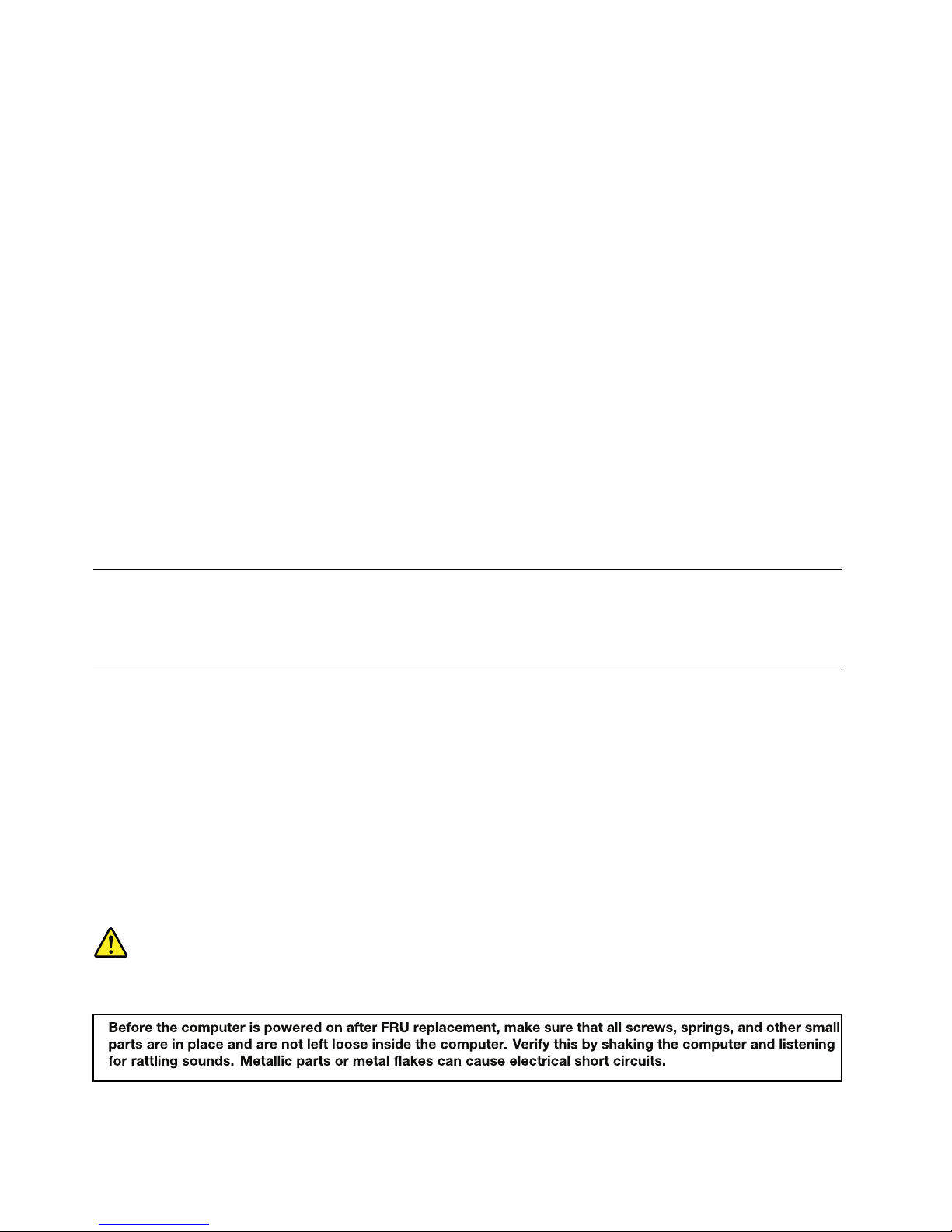
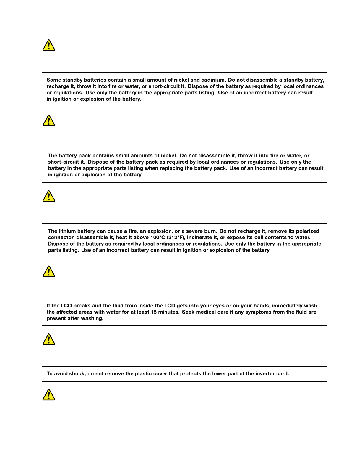
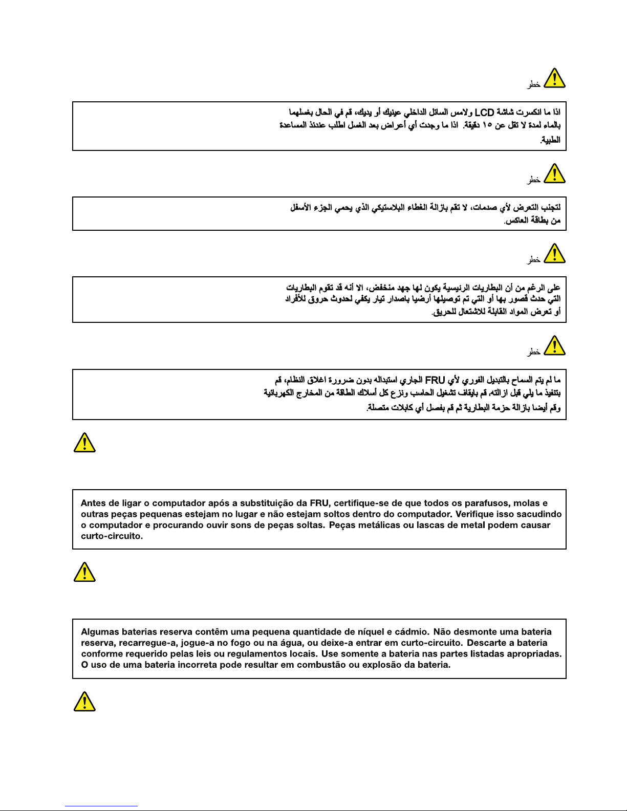
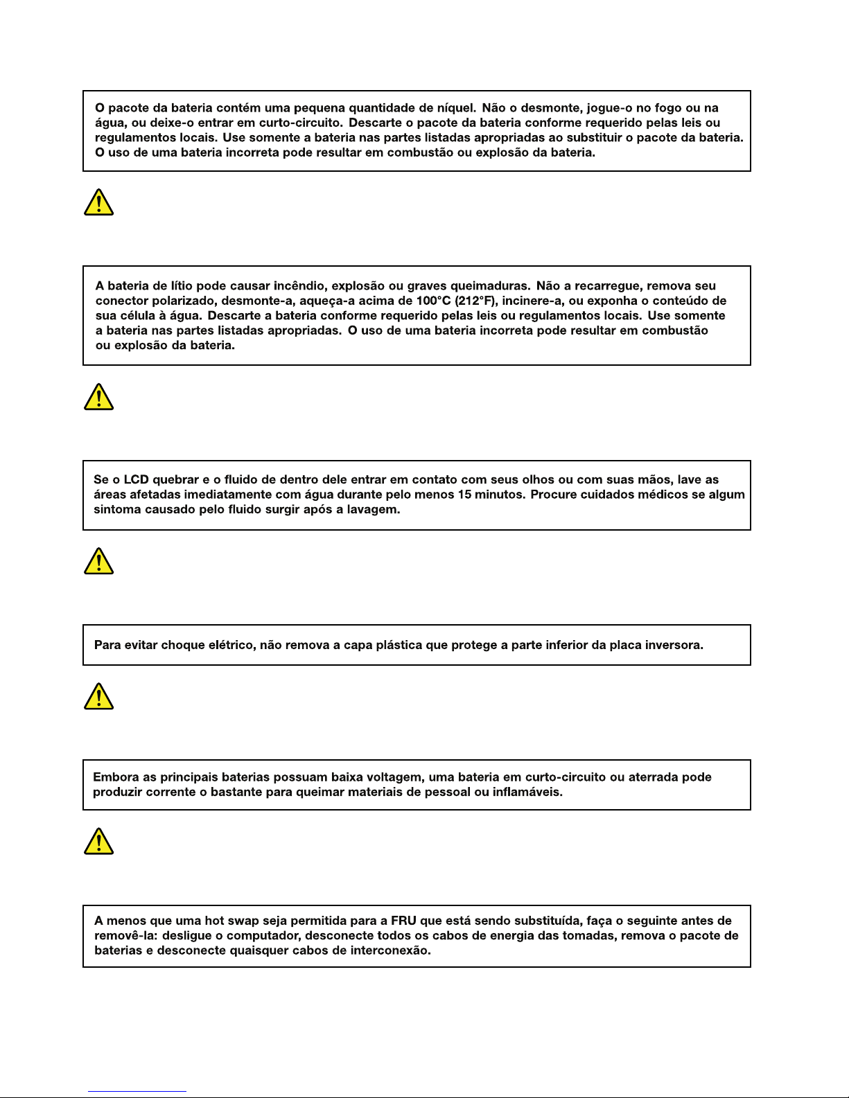
Note:Beforeusingthisinformationandtheproductitsupports,besuretoreadthegeneralinformation
underAppendixA“Notices”onpage121.
FirstEdition(October2013)
©CopyrightLenovo2013.
LIMITEDANDRESTRICTEDRIGHTSNOTICE:IfdataorsoftwareisdeliveredpursuantaGeneralServicesAdministration
“GSA”contract,use,reproduction,ordisclosureissubjecttorestrictionssetforthinContractNo.GS-35F-05925.
Page 3

Contents
Aboutthismanual...........iii
Chapter1.Safetyinformation......1
Generalsafety................1
Electricalsafety...............2
Safetyinspectionguide............3
Handlingdevicesthataresensitivetoelectrostatic
discharge..................3
Groundingrequirements............4
Safetynotices(multilingualtranslations)......4
Lasercompliancestatement(multilingual
translations)................17
Chapter2.Importantservice
information..............23
StrategyforreplacingFRUs.........23
Strategyforreplacingaharddiskdriveora
solid-statedrive............24
Importantnoticeforreplacingasystem
board................24
Howtouseerrorcodes.........24
StrategyforreplacingFRUsforCTO,specialbid
model,andstandardmodel.........24
Productdenition............24
FRUidentication............25
Chapter3.Generalcheckout.....27
Whattodorst..............27
Checkoutguide..............28
LenovoSolutionCenter.........28
Quicktestprograms...........28
UEFIdiagnosticprogram.........29
Bootablediagnosticprograms.......29
Powersystemcheckout...........30
Checkingtheacpoweradapter......30
Checkingoperationalcharging......31
Checkingthebatterypack........31
Checkingthecoin-cellbattery.......32
Chapter4.Relatedservice
information..............33
Restoringthefactorycontentsbyusingthe
productRecoveryDiscSet..........33
UsingtheWindowsrecoveryprogramsonthe
Windows8operatingsystem.........34
Refreshingyourcomputer........34
Resettingyourcomputertothefactorydefault
settings................34
Usingtheadvancedstartupoptions....35
RecoveringyouroperatingsystemifWindows
8failstostart.............35
Creatingandusingrecoverymedia.....35
Passwords................36
Power-onpassword...........36
Harddiskpassword...........37
Supervisorpassword..........37
Howtoremovethepower-onpassword...37
Howtoremovetheharddiskpassword...38
Powermanagement............38
Screenblankmode(fortheWindows7
operatingsystemonly)..........38
Sleepmode..............38
Hibernationmode...........39
Symptom-to-FRUindex...........39
Numericerrorcodes..........40
Errormessages............42
Beepsymptoms............42
No-beepsymptoms...........42
LCD-relatedsymptoms.........43
Intermittentproblems..........43
Undeterminedproblems.........43
Chapter5.Statusindicators.....45
Chapter6.Specialkeys........47
Chapter7.Locations.........49
Locatingcomputercontrols,connectors,and
indicators.................49
Frontview...............49
Rearview...............50
Bottomview..............50
LocatingFRUsandCRUs..........50
MajorFRUsandCRUs..........52
LCDFRUsandCRUs..........54
MiscellaneouskitsandotherFRUs.....57
LookingupFRUinformation.........57
Chapter8.FRUreplacement
notices................59
Screwnotices...............59
Retainingserialnumbers...........60
Restoringtheserialnumberofthesystem
unit.................60
RetainingtheUUID...........61
©CopyrightLenovo2013
i
Page 4

Chapter9.Removingorreplacinga
FRU..................63
Generalguidelines.............63
RemovingtheSIMcard...........64
1010Lenovo-OneLink-connectorcover.....65
1020Batterypack.............65
1030Largebottomcover..........66
1040Smallbottomcover..........67
1050Opticaldriveoroptical-drivebaybezel...68
1060Memorymodule............68
1070Harddiskdrivewithbracketorsolid-state
drivewithbracket.............69
1080Wireless-WANcardorM.2solid-statedrive.71
1090Wireless-LAN/Bluetoothcard.......73
1100Coin-cellbattery............74
1110Thermalmodule............75
1120Keyboard..............77
1130Keyboardbezelassembly........83
1140Microprocessor............86
1150Systemboard.............87
1160Media-card-reader/USBcard.......90
1170dc-in/Ethenetcardbracketanddc-in/Ethenet
card...................91
1180Speakerassembly...........94
1190Power-buttoncard...........95
1200LCDunit...............96
1210Basecoverassembly..........104
Formodelswithnon-touchscreen.......106
2010LCDbezel............106
2020LCDpanelandLCDhinges......107
2030Camera/microphonemoduleandLCD
cables................109
2040Wireless-LAN/WANantennaassembly
andLCDcoverkit...........111
Formodelswithtouchscreen.........112
2010LCDhingecapandLCDpanel/screen
assembly...............112
2020Camera/microphonemodule.....114
2030LCDcablesandLCD-control-card
cable.................115
2040LCDhinges............117
2050Wireless-LANantennaandLCDrear
cover................118
AppendixA.Notices.........121
Electronicemissionnotices..........122
Trademarks................122
AppendixB.Abbreviationand
acronymtable............123
iiHardwareMaintenanceManual
Page 5

Aboutthismanual
ThismanualcontainsserviceandreferenceinformationforthefollowingThinkPad
®
products:
ThinkPadEdgeE440
MachineTypes(MT)20C5
Usethismanualalongwiththeadvanceddiagnosticteststotroubleshootproblems.
Important:
ThismanualisintendedonlyfortrainedservicetechnicianswhoarefamiliarwithThinkPadproducts.Use
thismanualalongwiththeadvanceddiagnosticteststotroubleshootproblemseffectively.
BeforeservicingaThinkPadproduct,besuretoreadalltheinformationunderChapter1“Safety
information”onpage1andChapter2“Importantserviceinformation”onpage23.
©CopyrightLenovo2013
iii
Page 6

ivHardwareMaintenanceManual
Page 7

Chapter1.Safetyinformation
Thischapterpresentsthefollowingsafetyinformationthatyouneedtobefamiliarwithbeforeyouservicea
ThinkPadnotebookcomputer.
•“Generalsafety”onpage1
•“Electricalsafety”onpage2
•“Safetyinspectionguide”onpage3
•“Handlingdevicesthataresensitivetoelectrostaticdischarge”onpage3
•“Groundingrequirements”onpage4
•“Safetynotices(multilingualtranslations)”onpage4
•“Lasercompliancestatement(multilingualtranslations)”onpage17
Generalsafety
Followtheserulestoensuregeneralsafety:
•Observegoodhousekeepingintheareaofthemachinesduringandaftermaintenance.
•Whenliftinganyheavyobject:
1.Ensurethatyoucanstandsafelywithoutslipping.
2.Distributetheweightoftheobjectequallybetweenyourfeet.
3.Useaslowliftingforce.Nevermovesuddenlyortwistwhenyouattempttolift.
4.Liftbystandingorbypushingupwithyourlegmuscles;thisactionremovesthestrainfromthe
musclesinyourback.Donotattempttoliftanyobjectthatweighsmorethan16kg(35lb)orthat
youthinkistooheavyforyou.
•Donotperformanyactionthatcauseshazardstothecustomer,orthatmakestheequipmentunsafe.
•Beforeyoustartthemachine,ensurethatotherservicetechniciansandthecustomer'spersonnelare
notinahazardousposition.
•Placeremovedcoversandotherpartsinasafeplace,awayfromallpersonnel,whileyouareservicing
themachine.
•Keepyourtoolcaseawayfromwalkareassothatotherpeoplewillnottripoverit.
•Donotwearlooseclothingthatcanbetrappedinthemovingpartsofamachine.Ensurethatyoursleeves
arefastenedorrolledupaboveyourelbows.Ifyourhairislong,fastenit.
•Inserttheendsofyournecktieorscarfinsideclothingorfastenitwithanonconductiveclip,about8
centimeters(3inches)fromtheend.
•Donotwearjewelry,chains,metal-frameeyeglasses,ormetalfastenersforyourclothing.
Attention:Metalobjectsaregoodelectricalconductors.
•Wearsafetyglasseswhenyouarehammering,drilling,soldering,cuttingwire,attachingsprings,using
solvents,orworkinginanyotherconditionsthatmightbehazardoustoyoureyes.
•Afterservice,reinstallallsafetyshields,guards,labels,andgroundwires.Replaceanysafetydevice
thatiswornordefective.
•Reinstallallcoverscorrectlybeforereturningthemachinetothecustomer.
•Fanlouversonthemachinehelptopreventoverheatingofinternalcomponents.Donotobstructfan
louversorcoverthemwithlabelsorstickers.
©CopyrightLenovo2013
1
Page 8

Electricalsafety
Observethefollowingruleswhenworkingonelectricalequipment.
Important:
•Useonlyapprovedtoolsandtestequipment.Somehandtoolshavehandlescoveredwithasoftmaterial
thatdoesnotinsulateyouwhenworkingwithliveelectricalcurrents.
•Manycustomershave,neartheirequipment,rubberoormatsthatcontainsmallconductivebersto
decreaseelectrostaticdischarge(ESD).Donotusethistypeofmattoprotectyourselffromelectrical
shock.
•Findtheroomemergencypower-off(EPO)switch,disconnectingswitch,orelectricaloutlet.Ifanelectrical
accidentoccurs,youcanthenoperatetheswitchorunplugthepowercordquickly.
•Donotworkaloneunderhazardousconditionsornearequipmentthathashazardousvoltages.
•Disconnectallpowerbefore:
–Performingamechanicalinspection
–Workingnearpowersupplies
–Removingorinstallingmainunits
•Beforeyoustarttoworkonthemachine,unplugthepowercord.Ifyoucannotunplugit,askthecustomer
topoweroffthewallboxthatsuppliespowertothemachine,andtolockthewallboxintheoffposition.
•Ifyouneedtoworkonamachinethathasexposedelectricalcircuits,observethefollowingprecautions:
–Ensurethatanotherperson,familiarwiththepower-offcontrols,isnearyou.Thatpersonmustbethere
toswitchoffthepower,ifnecessary.
–Useonlyonehandwhenworkingwithpowered-onelectricalequipment;keeptheotherhandinyour
pocketorbehindyourback.
Attention:Anelectricalshockcanoccuronlywhenthereisacompletecircuit.Byobservingtheabove
rule,youmaypreventacurrentfrompassingthroughyourbody.
–Whenusingtesters,setthecontrolscorrectlyandusetheapprovedprobeleadsandaccessoriesfor
thattester.
–Standonsuitablerubbermats(obtainedlocally,ifnecessary)toinsulateyoufromgroundssuchas
metaloorstripsandmachineframes.
Observethespecialsafetyprecautionswhenyouworkwithveryhighvoltages.Instructionsforthese
precautionsareinthesafetysectionsofmaintenanceinformation.Useextremecarewhenmeasuring
highvoltages.
•Regularlyinspectandmaintainyourelectricalhandtoolsforsafeoperationalcondition.
•Donotusewornorbrokentoolsandtesters.
•Neverassumethatpowerhasbeendisconnectedfromacircuit.First,checkthatithasbeenpoweredoff.
•Alwayslookcarefullyforpossiblehazardsinyourworkarea.Examplesofthesehazardsaremoistoors,
nongroundedpowerextensioncables,powersurges,andmissingsafetygrounds.
•Donottouchliveelectricalcircuitswiththereectivesurfaceofaplasticdentalmirror.Thesurfaceis
conductive;suchtouchingcancausepersonalinjuryandmachinedamage.
•Donotservicethefollowingpartswiththepoweronwhentheyareremovedfromtheirnormaloperating
placesinamachine:
–Power-supplyunits
–Pumps
–Blowersandfans
–Motorgenerators
–Unitssimilartothoselistedabove
Thispracticeensurescorrectgroundingoftheunits.
2HardwareMaintenanceManual
Page 9

•Ifanelectricalaccidentoccurs:
–Usecaution;donotbecomeavictimyourself.
–Switchoffpower.
–Sendanotherpersontogetmedicalaid.
Safetyinspectionguide
Thepurposeofthisinspectionguideistoassistyouinidentifyingpotentiallyunsafeconditions.Aseach
machinewasdesignedandbuilt,requiredsafetyitemswereinstalledtoprotectusersandservicetechnicians
frominjury.Thisguideaddressesonlythoseitems.Y oushouldusegoodjudgmenttoidentifypotential
safetyhazardsduetoattachmentofnon- ThinkPadfeaturesoroptionsnotcoveredbythisinspectionguide.
Ifanyunsafeconditionsarepresent,youmustdeterminehowserioustheapparenthazardcouldbeand
whetheryoucancontinuewithoutrstcorrectingtheproblem.
Considertheseconditionsandthesafetyhazardstheypresent:
•Electricalhazards,especiallyprimarypower(primaryvoltageontheframecancauseseriousorfatal
electricalshock)
•Explosivehazards,suchasadamagedcathoderaytube(CRT)faceorabulgingcapacitor
•Mechanicalhazards,suchaslooseormissinghardware
Todeterminewhetherthereareanypotentiallyunsafeconditions,usethefollowingchecklistatthebeginning
ofeveryservicetask.Beginthecheckswiththepoweroff,andthepowercorddisconnected.
Checklist:
1.Checkexteriorcoversfordamage(loose,broken,orsharpedges).
2.T urnoffthecomputer.Disconnectthepowercord.
3.Checkthepowercordfor:
a.Athird-wiregroundconnectoringoodcondition.Useametertomeasurethird-wireground
continuityfor0.1ohmorlessbetweentheexternalgroundpinandtheframeground.
b.Thepowercordshouldbetheauthorizedtypespeciedforyourcomputer.Goto:
http://www.lenovo.com/serviceparts-lookup.
c.Insulationmustnotbefrayedorworn.
4.Checkforcrackedorbulgingbatteries.
5.Removethecover.
6.Checkforanyobviousnon-ThinkPadalterations.Usegoodjudgmentastothesafetyofany
non-ThinkPadalterations.
7.Checkinsidetheunitforanyobviousunsafeconditions,suchasmetallings,contamination,wateror
otherliquids,orsignsofreorsmokedamage.
8.Checkforworn,frayed,orpinchedcables.
9.Checkthatthepower-supplycoverfasteners(screwsorrivets)havenotbeenremovedortamperedwith.
Handlingdevicesthataresensitivetoelectrostaticdischarge
Anycomputerpartcontainingtransistorsorintegratedcircuits(ICs)shouldbeconsideredsensitiveto
ESD.ESDdamagecanoccurwhenthereisadifferenceinchargebetweenobjects.ProtectagainstESD
damagebyequalizingthechargesothatthemachine,thepart,theworkmat,andthepersonhandlingthe
partareallatthesamecharge.
Chapter1.Safetyinformation3
Page 10
Notes:
1.Useproduct-specicESDprocedureswhentheyexceedtherequirementsnotedhere.
2.EnsurethattheESDprotectivedevicesyouusehavebeencertied(ISO9000)asfullyeffective.
WhenhandlingESD-sensitiveparts:
•Keepthepartsinprotectivepackagesuntiltheyareinsertedintotheproduct.
•Avoidcontactwithotherpeople.
•Wearagroundedwriststrapagainstyourskintoeliminatestaticonyourbody.
•Preventthepartfromtouchingyourclothing.Mostclothingisinsulativeandretainsachargeevenwhen
youarewearingawriststrap.
•Useagroundedworkmattoprovideastatic-freeworksurface.Thematisespeciallyusefulwhen
handlingESD-sensitivedevices.
•Selectagroundingsystem,suchasthoselistedbelow,toprovideprotectionthatmeetsthespecic
servicerequirement.
Note:TheuseofagroundingsystemtoguardagainstESDdamageisdesirablebutnotnecessary.
–AttachtheESDgroundcliptoanyframeground,groundbraid,orgreen-wireground.
–Whenworkingonadouble-insulatedorbattery-operatedsystem,useanESDcommongroundor
referencepoint.Youcanusecoaxorconnector-outsideshellsonthesesystems.
–Usetheroundgroundprongoftheacplugonac-operatedcomputers.
Groundingrequirements
Electricalgroundingofthecomputerisrequiredforoperatorsafetyandcorrectsystemfunction.Proper
groundingoftheelectricaloutletcanbeveriedbyacertiedelectrician.
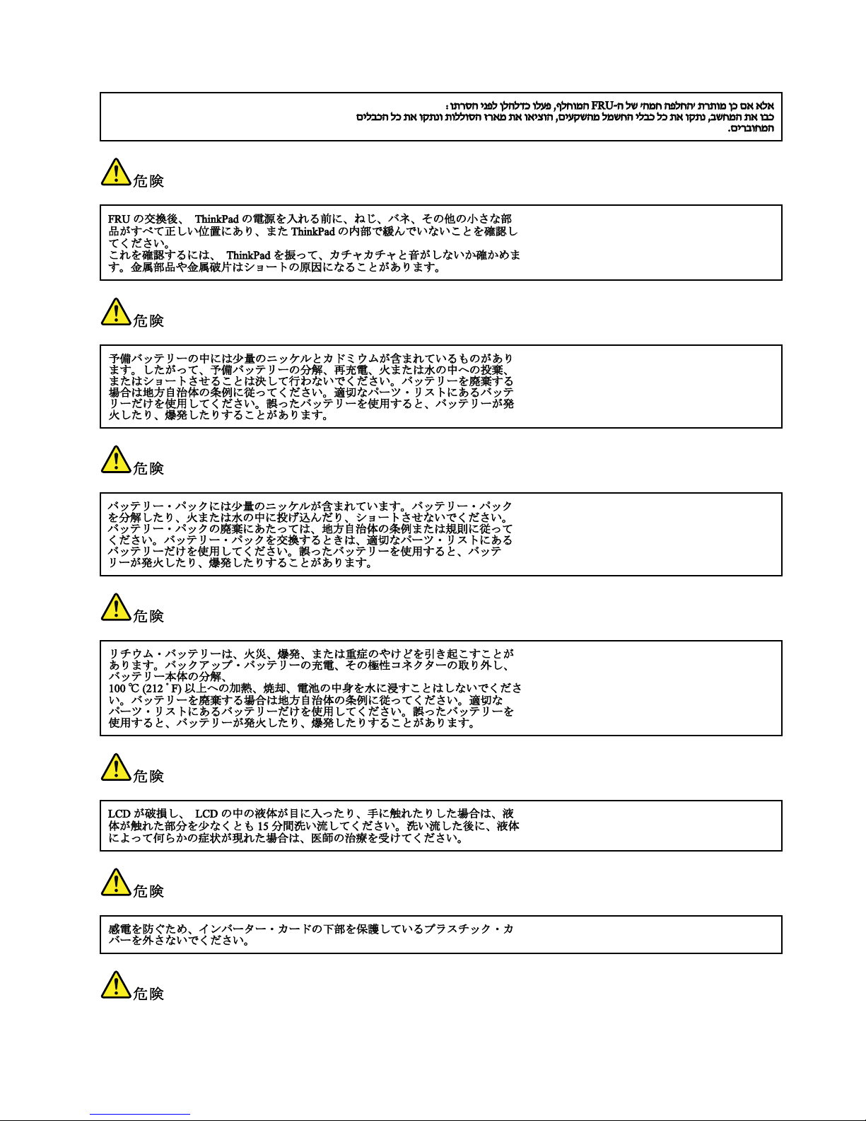
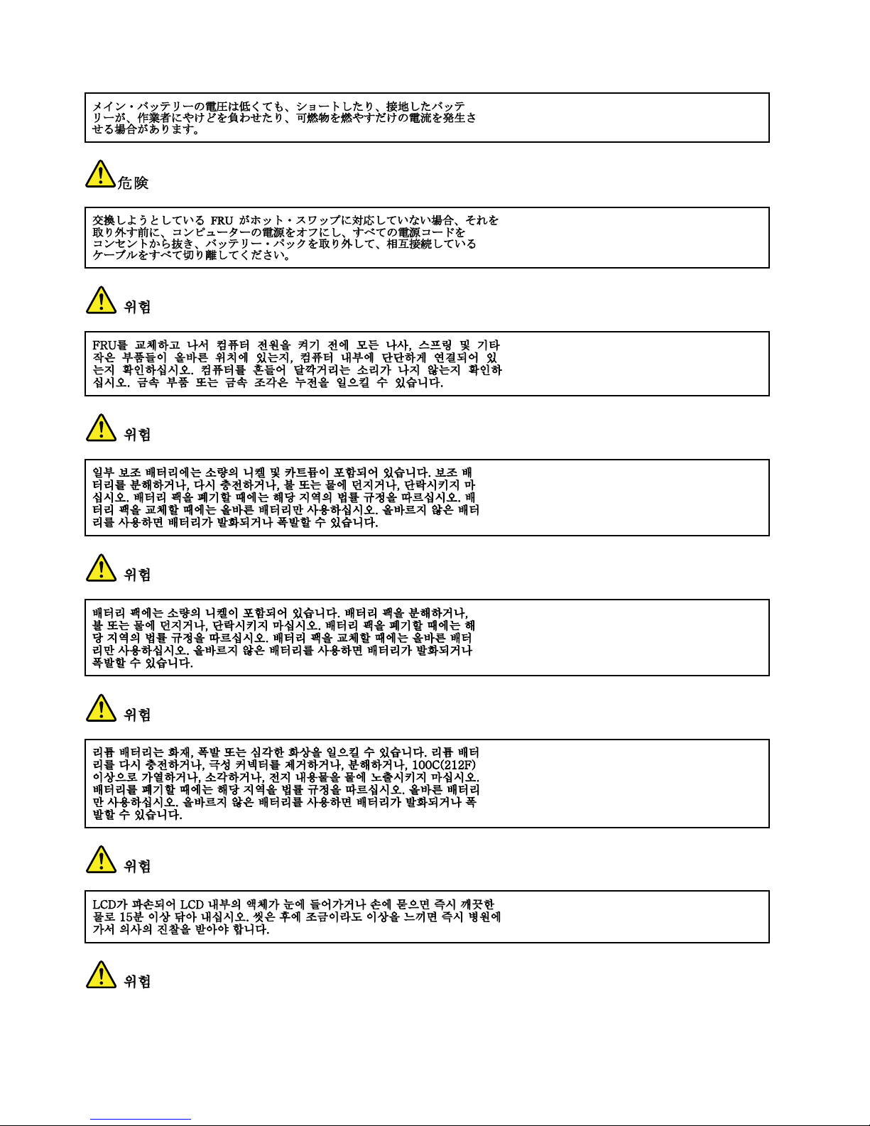
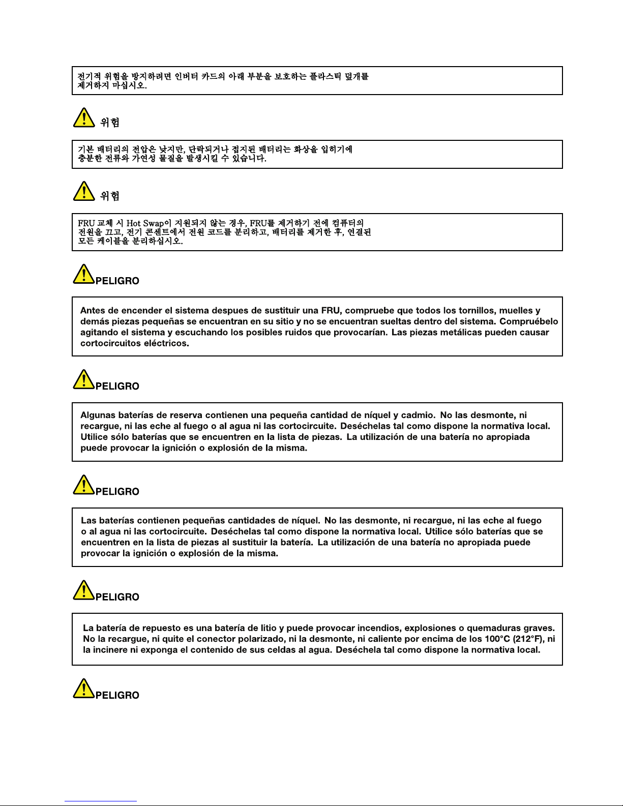
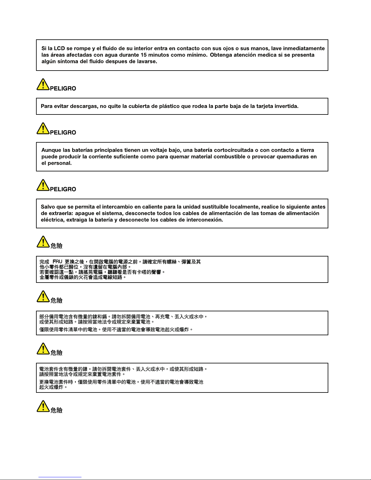
Safetynotices(multilingualtranslations)
Thesafetynoticesinthissectionareprovidedinthefollowinglanguages:
•English
•Arabic
•BrazilianPortuguese
•French
•German
•Hebrew
•Japanese
•Korean
•Spanish
•T raditionalChinese
DANGER
4HardwareMaintenanceManual
Page 11
DANGER
DANGER
DANGER
DANGER
DANGER
DANGER
Chapter1.Safetyinformation5
Page 12

DANGER
6HardwareMaintenanceManual
Page 13
PERIGO
PERIGO
PERIGO
Chapter1.Safetyinformation7
Page 14
PERIGO
PERIGO
PERIGO
PERIGO
PERIGO
8HardwareMaintenanceManual
Page 15
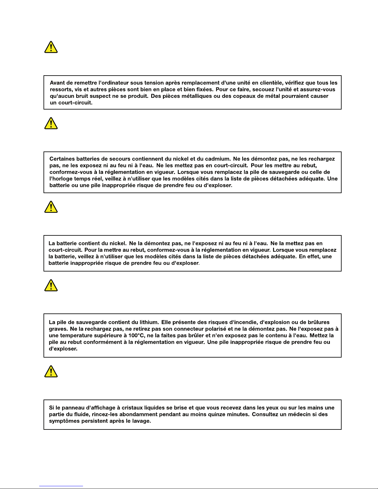
DANGER
DANGER
DANGER
DANGER
DANGER
Chapter1.Safetyinformation9
Page 16
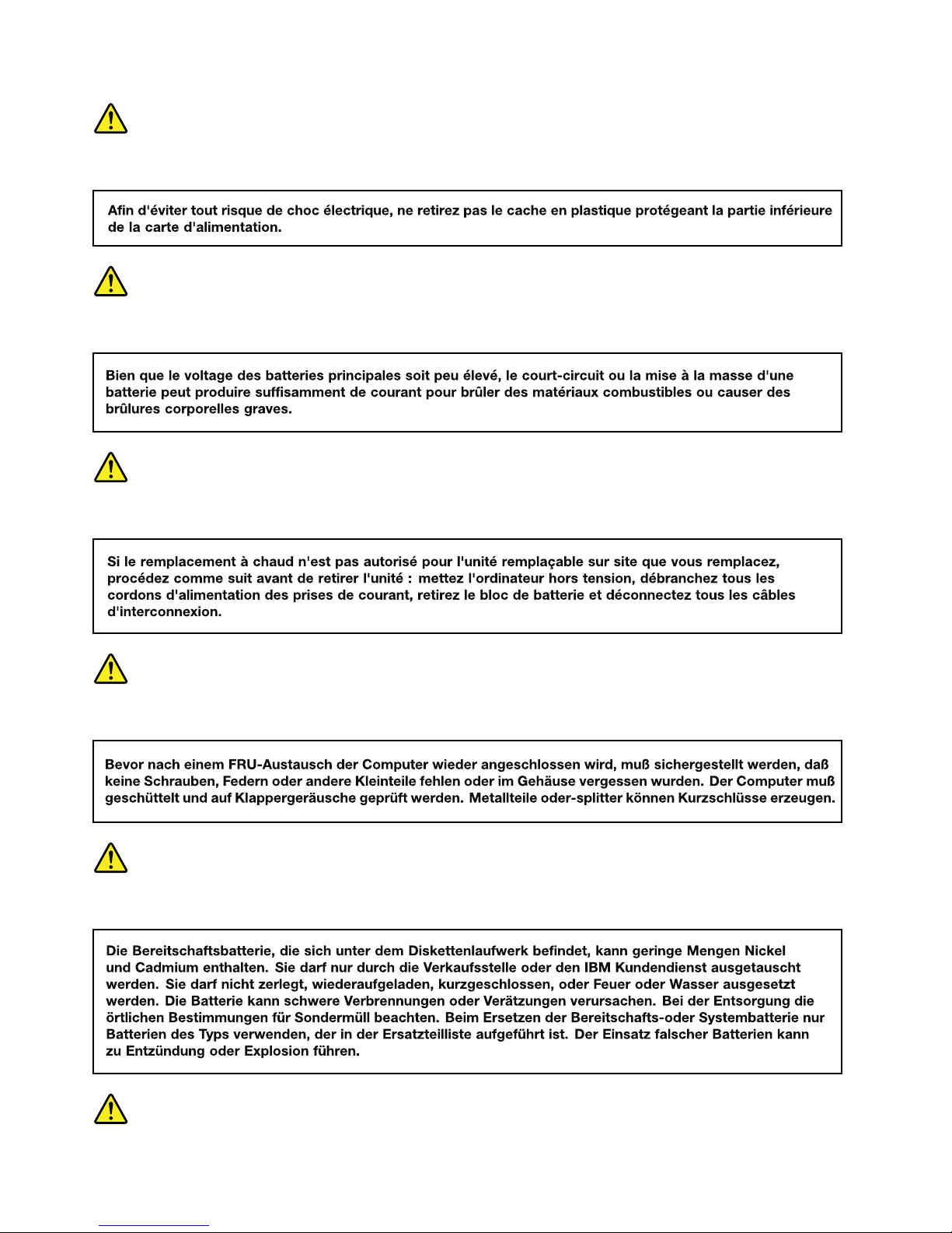
DANGER
DANGER
DANGER
VORSICHT
VORSICHT
10HardwareMaintenanceManual
Page 17
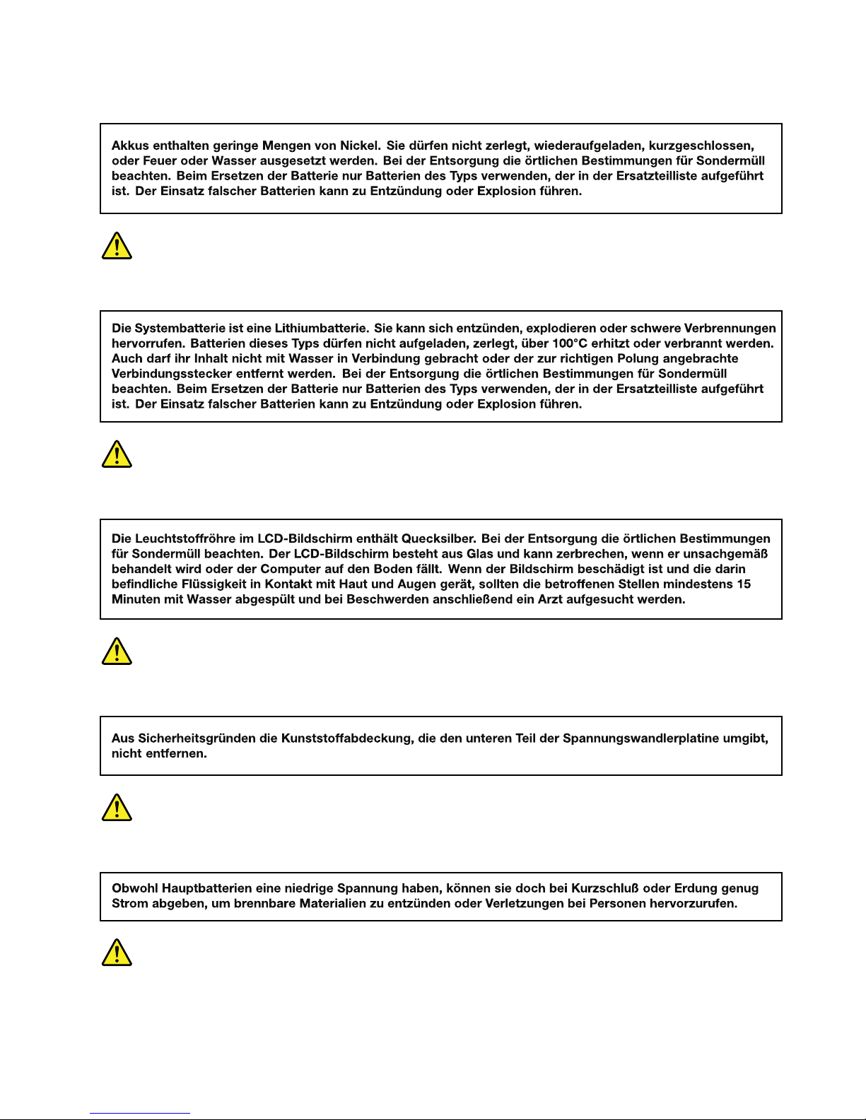
VORSICHT
VORSICHT
VORSICHT
VORSICHT
VORSICHT
VORSICHT
Chapter1.Safetyinformation11
Page 18
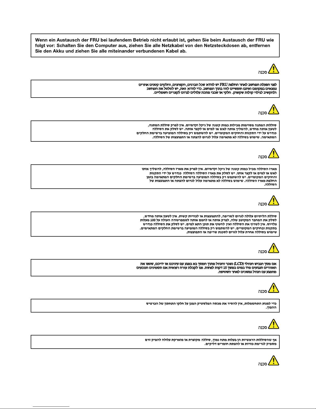
12HardwareMaintenanceManual
Page 19
Chapter1.Safetyinformation13
Page 20
14HardwareMaintenanceManual
Page 21
Chapter1.Safetyinformation15
Page 22
16HardwareMaintenanceManual
Page 23
Lasercompliancestatement(multilingualtranslations)
Thelasercompliancestatementsinthissectionareprovidedinthefollowinglanguages:
•English
•Arabic
•BrazilianPortuguese
•French
•German
•Hebrew
•Japanese
•Korean
•Spanish
•T raditionalChinese
Chapter1.Safetyinformation17
Page 24
18HardwareMaintenanceManual
Page 25
Chapter1.Safetyinformation19
Page 26
20HardwareMaintenanceManual
Page 27
Chapter1.Safetyinformation21
Page 28
22HardwareMaintenanceManual
Page 29

Chapter2.Importantserviceinformation
ThischapterpresentsthefollowingimportantserviceinformationthatappliestotheMTsupportedby
thismanual:
•“StrategyforreplacingFRUs”onpage23
–“Strategyforreplacingaharddiskdriveorasolid-statedrive”onpage24
–“Importantnoticeforreplacingasystemboard”onpage24
–“Howtouseerrorcodes”onpage24
•“StrategyforreplacingFRUsforCTO,specialbidmodel,andstandardmodel”onpage24
–“Productdenition”onpage24
–“FRUidentication”onpage25
Important:
•IfthecomputerisequippedwithbothaharddiskdriveandanM.2solid-statedrive,donotusetheM.2
solid-statedriveasabootabledevice.TheM.2solid-statedriveisdesignedanddevelopedfor“cache”
functionpurposeonly.
•AdvisecustomerstocontacttheLenovo
®
CustomerSupportCenteriftheyneedanyassistancein
obtainingorinstallinganysoftwarexes,drivers,andUniedExtensibleFirmwareInterface(UEFI)basic
input/outputsystem(BIOS)downloads.TelephonenumbersforLenovoSupportareavailableat:
http://www.lenovo.com/support/phone
•SystemdisassemblyandreassemblyvideosthatshowtheFieldReplaceableUnit(FRU)removalor
replacementproceduresfortheLenovoauthorizedservicetechniciansareavailableat:
http://www.lenovoservicetraining.com/ion/
StrategyforreplacingFRUs
Beforereplacingparts:
Ensurethatallsoftwarexes,drivers,andUEFIBIOSdownloadsareinstalledbeforeyoureplaceany
FRUslistedinthismanual.
Afterasystemboardisreplaced,ensurethatthelatestUEFIBIOSisloadedtothesystemboardbeforeyou
completetheserviceaction.
Todownloadandinstallsoftwarexes,drivers,andUEFIBIOS,gotohttp://www.lenovo.com/ThinkPadDrivers
andfollowtheinstructionsonthescreen.
UsethefollowingstrategytopreventunnecessaryexpenseforreplacingandservicingFRUs:
•IfyouareinstructedtoreplaceaFRUbutthereplacementdoesnotcorrecttheproblem,reinstallthe
originalFRUbeforeyoucontinue.
•Somecomputershavebothaprocessorboardandasystemboard.Ifyouareinstructedtoreplaceeither
theprocessorboardorthesystemboard,andreplacingoneofthemdoesnotcorrecttheproblem,
reinstallthatboard,andthenreplacetheotherone.
•IfanadapteroradeviceconsistsofmorethanoneFRU,anyoftheFRUsmightbethecauseoftheerror.
Beforereplacingtheadapterordevice,removetheFRUs,onebyone,toseeifthesymptomschange.
ReplaceonlytheFRUthatchangedthesymptoms.
©CopyrightLenovo2013
23
Page 30

Strategyforreplacingaharddiskdriveorasolid-statedrive
Alwaystrytorunalow-levelformatoperationbeforereplacingaharddiskdriveorasolid-statedrive.This
willcauseallcustomerdataonthedrivetobelost.Ensurethatthecustomerhasacurrentbackupof
thedatabeforeyouperformthistask.
Attention:Thedrivestartupsequenceinthecomputeryouareservicingmighthavebeenchanged.Be
extremelycarefulduringwriteoperationssuchascopying,saving,orformatting.Ifyouselectanincorrect
drive,dataorprogramscanbeoverwritten.
IfthecomputerisshippedwithbothanM.2solid-statedriveandaharddiskdrive,theM.2solid-statedrive
isusedforthe“cache”functionandtosupporttheIntel®RapidStartT echnology.Werecommendthat
usersdonotreplacetheM.2solid-statedrivebythemselves.Otherwise,the“cache”functionwillnotwork
andtheIntelRapidStartTechnologycannotbeusedanymore.
Attention:EnsurethatyoupartitiontheM.2solid-statedriveafterinstallingitonthecomputeryouare
servicing.Otherwise,theM.2solid-statedrivewillnotfunctioncorrectly.Forinstructionsonhowtopartition
anM.2solid-statedrive,gotohttp://www.lenovo.com/support/msata-fru.
Importantnoticeforreplacingasystemboard
Somecomponentsmountedonasystemboardareverysensitive.Improperhandlingofasystemboardcan
causedamagetothosecomponents,andmaycauseasystemmalfunction.
Attention:Whenhandlingasystemboard:
•Donotdropasystemboardorapplyanyexcessiveforcetoit.
•Avoidroughhandlingofanykind.
•AvoidbendingasystemboardandhardpushingtopreventcrackingateachBallGridArray(BGA)chipset.
Howtouseerrorcodes
Usetheerrorcodesdisplayedonthescreentodiagnosefailures.Ifmorethanoneerrorcodeisdisplayed,
beginthediagnosiswiththersterrorcode.Whatevercausesthersterrorcodemightalsocausefalse
errorcodes.Ifnoerrorcodeisdisplayed,seewhethertheerrorsymptomislistedinthe“Symptom-to-FRU
Index”section.
StrategyforreplacingFRUsforCTO,specialbidmodel,andstandard
model
ThistopicprovidesinformationaboutthemodeltypesandFRUidentication.
Productdenition
Thistopicintroducesdifferentmodeltypesandhowtoidentifyeachtype.
DynamicCongureT oOrder(CTO)
ThismodelprovidestheabilityforacustomertocongureaLenovosolutionfromaWebsite,andhavethis
congurationsenttofulllment,whereitisbuiltandshippeddirectlytothecustomer.Themachinelabel,
iBase,andeSupportwillloadtheseproductsasthe4-characterMT,4-charactermodel,and2-character
countrycode.Themodelis“CTO1”andthedefaultcountrycodeis“WW”(example:20AACTO1WW).
Specialbidmodel
ThismodelisauniquecongurationthathasbeennegotiatedbetweenLenovoandthecustomer.Aunique
MTMconsistsofa4-characterMT ,a4-charactermodel,andanumeric2-charactercountrycodeisprovided
24HardwareMaintenanceManual
Page 31

tothecustomertoplaceorders(example:20AA000955).Thecountrycodeassignedisnumericanddoes
notdesignateaspeciccountryorregion.ThecustommodelfactsheetfortheMTMindicateswhichcountry
thespecial-bidMTMissetupfor.Special-bidofferingisnotgenerallyannounced.
Standardmodel
Standardmodels(xedconguration)areannouncedandofferedtoallcustomers.TheMTMportionofthe
machinelabelconsistsofa4-characterMT ,a4-charactermodel,andanalphabetic2-charactercountry
code.Thecountrycodeassignedisalphabeticandrepresentsadesignatedcountryorregion(example:
20AA0009UK).
FRUidentication
UseLenovoeSupporttoidentifymajorFRUs,FRUpartnumbers,andFRUdescriptionsforaproductatan
MT-serialnumberlevel.ExamplesofmajorFRUsareharddiskdrive,systemboard,liquidcrystaldisplay
(LCD),andmemorymodule.
ToidentifythemajorFRUsforaproduct,dothefollowing:
1.Goto:
http://www.lenovo.com/support
2.ClickWarranty&Services.
3.ClickCheckWarrantyStatus.
4.OntheWarrantyStatusLookuppage,clickPartsLookup.
5.T ypeyourMTandserialnumber,andthenclickSubmit.
eSupportalsocanbeusedtoviewthegeneralFRUlistforaproduct.
TogetthegeneralFRUlistforaproduct,dothefollowing:
1.Goto:
http://www.lenovo.com/support
2.ClickParts&Accessories.
3.Followtheinstructionsonthescreentoselectproduct.
4.ClickProductsandPartsDetail.
5.OnthePRODUCTANDPARTSDET AILpage,clickthePartsDetailtabtoviewtheFRUlist.
Note:TheFRUlistisagenerallistofcomponentsanddoesnotcontainspecicmodelinformation.
Chapter2.Importantserviceinformation25
Page 32

26HardwareMaintenanceManual
Page 33

Chapter3.Generalcheckout
Thischapterpresentsfollowinginformation:
•“Whattodorst”onpage27
•“Checkoutguide”onpage28
–“Quicktestprograms”onpage28
–“UEFIdiagnosticprogram”onpage29
–“Bootablediagnosticprograms”onpage29
•“Powersystemcheckout”onpage30
Somedescriptionsinthischaptermightnotapplytoyourparticularcomputer.
Beforeyougotothecheckoutguide,besuretoreadthefollowingimportantnotes.
Importantnotes:
•Onlycertiedtrainedpersonnelshouldservicethecomputer.
•BeforereplacinganyFRU,readtheentirepageonremovingandreplacingFRUs.
•WhenyoureplaceFRUs,itisrecommendedtousenewnylon-coatedscrews.
•Beextremelycarefulduringsuchwriteoperationsascopying,saving,orformatting.Drivesinthecomputer
thatyouareservicingsequencemighthavebeenaltered.Ifyouselectanincorrectdrive,dataorprograms
mightbeoverwritten.
•ReplaceaFRUonlywithanotherFRUofthecorrectmodel.WhenyoureplaceaFRU,ensurethatthemodelof
themachineandtheFRUpartnumberarecorrect.
•AFRUshouldnotbereplacedbecauseofasingle,unreproduciblefailure.Singlefailurescanoccurfora
varietyofreasonsthathavenothingtodowithahardwaredefect,suchascosmicradiation,ESD,orsoftware
errors.ConsiderreplacingaFRUonlywhenaproblemrecurs.IfyoususpectthataFRUisdefective,cleartheerror
logandrunthetestagain.Iftheerrordoesnotrecur,donotreplacetheFRU.
•BecarefulnottoreplaceanondefectiveFRU.
Whattodorst
WhenyoureturnaFRU,youmustincludethefollowinginformationinthepartsexchangeformorparts
returnformthatyouattachtoit:
1.Nameandphonenumberofservicetechnician
2.Dateofservice
3.Dateonwhichthemachinefailed
4.Dateofpurchase
5.Failuresymptoms,errorcodesappearingonthedisplay,andbeepsymptoms
6.ProcedureindexandpagenumberinwhichthefailingFRUwasdetected
7.FailingFRUnameandpartnumber
8.MT ,modelnumber,andserialnumber
9.Customer'snameandaddress
Note:Duringthewarrantyperiod,thecustomermayberesponsibleforrepaircostsifthecomputerdamage
wascausedbymisuse,accident,modication,unsuitablephysicaloroperatingenvironment,orimproper
maintenancebythecustomer.Followingisalistofsomecommonitemsthatarenotcoveredunderwarranty
andsomesymptomsthatmightindicatethatthesystemwassubjecttostressbeyondnormaluse.
Beforecheckingproblemswiththecomputer,determinewhetherthedamageiscoveredunderthewarranty
byreferringtothefollowinglist:
Thefollowingarenotcoveredunderwarranty:
©CopyrightLenovo2013
27
Page 34

•LCDpanelcrackedfromtheapplicationofexcessiveforceorfrombeingdropped
•Scratched(cosmetic)parts
•Distortion,deformation,ordiscolorationofthecosmeticparts
•Plasticparts,latches,pins,orconnectorsthathavebeencrackedorbrokenbyexcessiveforce
•Damagecausedbyliquidspilledintothesystem
•DamagecausedbytheimproperinsertionofaPCCardortheinstallationofanincompatiblecard
•Improperdiscinsertionoruseofanopticaldrive
•Diskettedrivedamagecausedbypressureonthediskettedrivecover,foreignmaterialinthedrive,
ortheinsertionofadiskettewithmultiplelabels
•Damagedorbentdisketteejectbutton
•Fusesblownbyattachmentofanonsupporteddevice
•Forgottencomputerpassword(makingthecomputerunusable)
•Stickykeyscausedbyspillingaliquidontothekeyboard
•Useofanincorrectacpoweradapteronlaptopproducts
Thefollowingsymptomsmightindicatedamagecausedbynonwarrantedactivities:
•Missingpartsmightbeasymptomofunauthorizedserviceormodication.
•Checkforobviousdamagetoaharddiskdrive.Ifthespindleofaharddiskdrivebecomesnoisy,thehard
diskdrivemighthavebeendroppedorsubjecttoexcessiveforce.
Checkoutguide
UsethefollowingproceduresasaguideinidentifyingandcorrectingproblemswiththeThinkPadnotebook
computer.
Note:ThediagnostictestsareintendedtotestonlyThinkPadproducts.Theuseofnon- ThinkPadproducts,
prototypecards,ormodiedoptionscanleadtofalseindicationsoferrorsandinvalidsystemresponses.
1.Identifythefailingsymptomsinasmuchdetailaspossible.
2.Verifythesymptoms.Trytore-createthefailurebyrunningthediagnostictestorbyrepeatingthe
operation.
LenovoSolutionCenter
TheLenovoSolutionCenterprogramenablesyoutotroubleshootandresolvecomputerproblems.It
combinesdiagnostictests,systeminformationcollection,securitystatus,andsupportinformation,along
withhintsandtipsformaximumsystemperformance.
TheLenovoSolutionCenterprogramisavailablefordownloadathttp://www.lenovo.com/diags
ToruntheLenovoSolutionCenterprogram,gotoControlPanelandclickSystemandSecurity➙Lenovo
➙SystemHealthandDiagnostics,andthenfollowtheinstructionsonthescreen.
FormoreinformationabouttheLenovoSolutionCenterprogram,refertothehelpinformationsystem
oftheprogram.
Quicktestprograms
Runquicktestprogramstotroubleshootandresolvecomputerproblems,especiallywhenthecomputer
doesnothavetheLenovoSolutionCenterprograminstalled.
Lenovoprovidesthefollowingquicktestprograms:
•LenovoHardDriveQuickTest:Usethisprogramtotroubleshootandresolveinternalstorageproblems.
•LenovoMemoryQuickT est:Usethisprogramtotroubleshootandresolvememorymoduleproblems.
28HardwareMaintenanceManual
Page 35
Thequicktestprogramsareapplicableonthefollowingoperatingsystems:
•Microsoft
®
Windows
®
8
•MicrosoftWindows7
•MicrosoftWindowsXP
•MicrosoftWindowsServer
®
2003
•MicrosoftWindowsServer2008
Todownloadandinstallaquicktestprogram,gotohttp://www.lenovo.com/diagsandfollowtheinstructions
ontheWebsite.
Torunatestusingaquicktestprogram,dothefollowing:
1.GototheC:\SWTOOLS\ldiagdirectory.
2.Double-clickthegui_lsc_lite.exele.
3.WhentheUserAccountControlwindowopens,clickYes.
4.Selectthedeviceclasstobetested.
5.Selectthedevicestobetested.
6.Selectthetesttobeperformed.
7.Followtheinstructionsonthescreentostartthetest.Whenaproblemisdetected,information
messagesaredisplayed.Refertothemessagestotroubleshoottheproblem.
UEFIdiagnosticprogram
AUEFIdiagnosticprogramispreinstalledonthecomputer.Itenablesyoutotestmemorymodulesand
internalstoragedevices,viewsysteminformation,andcheckandrecoverbadsectorsoninternalstorage
devices.
ToruntheUEFIdiagnosticprogram,dothefollowing:
1.T urnonthecomputer.Ifthecomputercannotbeturnedon,goto“Powersystemcheckout”onpage30,
andcheckthepowersources.Ifanerrorcodeisdisplayed,goto“Symptom-to-FRUindex”onpage39
forerrorcodedescriptionsandtroubleshootinghints.
2.Whenthelogoscreenisdisplayed,repeatedlypressandreleasetheF10key.Themainscreenofthe
UEFIdiagnosticprogramisdisplayed.
3.Followtheinstructionsonthescreentousetheprogram.
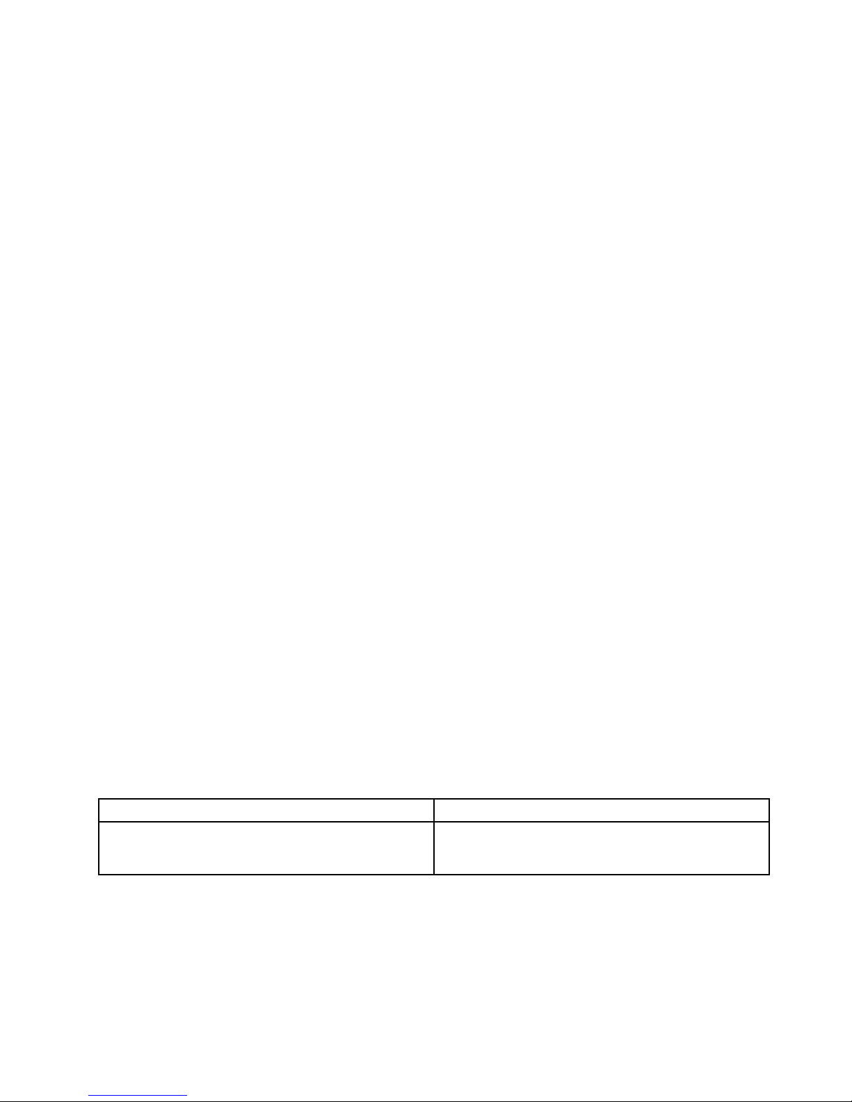
Theoptionsonthemainscreenareasfollows:
Table1.ItemsonthemainscreenoftheUEFIdiagnosticprogram
TestsTools
•QuickMemoryT est
•QuickStorageDeviceT est
•ExitApplication
•SystemInformation
•RecoverBadSectorsTool
Bootablediagnosticprograms
IfthecomputeryouareservicingisnotinstalledwiththeUEFIdiagnosticprogram,youcandownloada
bootablediagnosticprogramfromtheLenovoSupportWebsite.Thebootablediagnosticprogramsenable
youtotestcomputermemoryandinternalstoragedevices,viewsysteminformation,andcheckandrecover
theinternalstoragedevices.T ousethebootablediagnosticprograms,youcancreateabootablediagnostic
mediumonaUniversalSerialBus(USB)deviceorCD.
Chapter3.Generalcheckout29
Page 36

Tocreateabootablediagnosticmedium,dothefollowing:
1.Gotohttp://www.lenovo.com/diags.
2.ClickLenovoBootableDiagnostics.
3.FollowtheinstructionsontheWebsitetocreateabootablediagnosticmediumonaUSBdeviceorCD.
Tousethediagnosticmediumyouhavecreated,dooneofthefollowing:
•IfyouhavecreatedthebootablediagnosticmediumonaUSBdevice,dothefollowing:
1.AttachtheUSBdevicetothecomputer.
2.T urnonthecomputer.Ifthecomputercannotbeturnedon,goto“Powersystemcheckout”onpage
30,andcheckthepowersources.Ifanerrorcodeisdisplayed,goto“Symptom-to-FRUindex”on
page39forerrorcodedescriptionsandtroubleshootinghints.
3.Whenthelogoscreenisdisplayed,repeatedlypressandreleasetheF12key.WhentheBootMenu
windowopens,releasetheF12key.
4.UsethearrowkeystoselectUSBHDDandthenpressEnter.Thediagnosticprogramwillbe
launchedautomatically.
5.Followtheinstructionsonthescreentousethediagnosticprogram.
•IfyouhavecreatedthebootablediagnosticmediumonaCD,dothefollowing:
1.T urnonthecomputer.Ifthecomputercannotbeturnedon,goto“Powersystemcheckout”onpage
30
,andcheckthepowersources.Ifanerrorcodeisdisplayed,goto“Symptom-to-FRUindex”on
page39forerrorcodedescriptionsandtroubleshootinghints.
2.InserttheCDintotheopticaldrive.
3.Restartthecomputer.
4.Whenthelogoscreenisdisplayed,repeatedlypressandreleasetheF12key.WhentheBootMenu
windowopens,releasetheF12key.
5.UsethearrowkeystoselectA T APICDx(x:0,1,...)andthenpressEnter.Thediagnosticprogram
willbelaunchedautomatically.
6.Followtheinstructionsonthescreentousethediagnosticprogram.
Powersystemcheckout
Toverifyifabatterypackoranacpoweradapterisfunctional,dothefollowing:
1.T urnoffthecomputer.
2.Removethebatterypack.
3.Connecttheacpoweradapter.
4.Checkthatpowerissuppliedwhenyouturnonthecomputer.
5.T urnoffthecomputer.
6.Disconnecttheacpoweradapterandinstallthechargedbatterypack.
7.Checkthatthebatterypacksuppliespowerwhenyouturnonthecomputer.
Ifyoususpectapowerproblem,seetheappropriateoneofthefollowingpower-supplycheckouts:
•“Checkingtheacpoweradapter”onpage30
•“Checkingoperationalcharging”onpage31
•“Checkingthebatterypack”onpage31
•“Checkingthecoin-cellbattery”onpage32
Checkingtheacpoweradapter
Ifyourcomputerfailsonlywhentheacpoweradapterisused,usethefollowinginstructions.
•Ifthepowerproblemoccursonlywhenthedockisused,replacethedock.
30HardwareMaintenanceManual
Page 37
•Ifthesystem-statusindicator(theindicatorinthelogoscreen)doesnotblinkthreetimeswhenanacpower
sourceisconnected,checkthepowercordoftheacpoweradapterforcorrectcontinuityandinstallation.
•Ifthecomputerdoesnotchargeduringoperation,goto“Checkingoperationalcharging”onpage31.
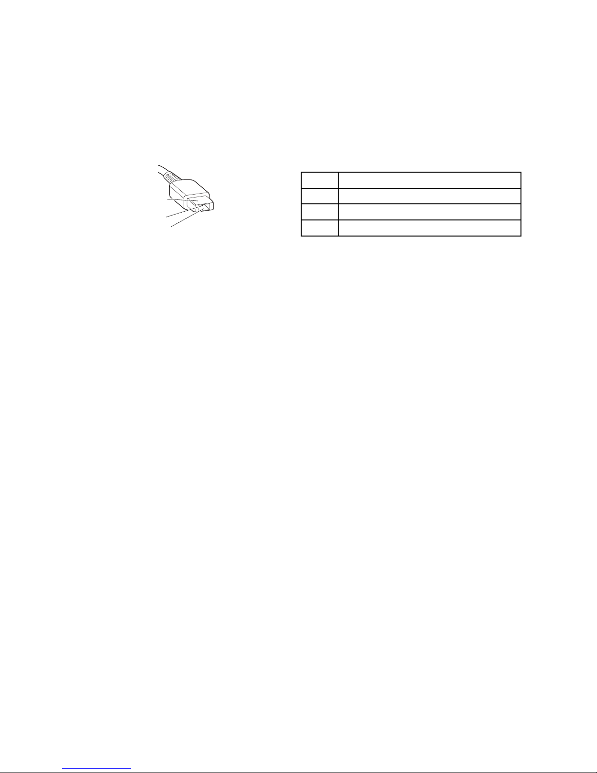
Tochecktheacpoweradapter,dothefollowing:
1.Unplugtheacpoweradaptercablefromthecomputer.
2.Measuretheoutputvoltageattheplugoftheacpoweradaptercable.Seethefollowingillustration:
Pin
Voltage(Vdc)
1+20
20
3
Ground
(20V)
1
3
2
Note:Outputvoltageacrosspin2oftheacpoweradaptermightdifferfromtheoneyouareservicing.
3.Ifthevoltageisnotcorrect,replacetheacpoweradapter.
4.Ifthevoltageisacceptable,replacethesystemboard.
Note:Noisefromtheacpoweradapterdoesnotalwaysindicateadefect.
Checkingoperationalcharging
Tocheckwhetherthebatterypackchargescorrectlyduringoperation,dothefollowing:
1.Dischargethebatterypackuntiltheremainingbatterypowerislessthan50%.
2.Connectthecomputertoacpowertochargethebatterypack.IfthebatterystatusiconintheWindows
noticationareaindicatesthatthebatteriesarenotcharging,removethebatterypackandletthem
returntoroomtemperature.
3.Reinstallthebatterypack.Ifthebatteriesarestillnotcharging,replacethebatterypack.
4.Checkthebatterystatusiconagain.Ifthesameerrorstillexists,replacethesystemboard.Otherwise,
checktheoriginalbatterypack.See“Checkingthebatterypack”onpage31.
Checkingthebatterypack
ThissystemsupportsonlybatteriesspeciallydesignedforthisspecicsystemandmanufacturedbyLenovo
oranauthorizedbuilder.Thesystemdoesnotsupportunauthorizedbatteriesorbatteriesdesignedforother
systems.Ifanunauthorizedbatterypackorabatterypackdesignedforanothersystemisinstalled,the
systemwillnotcharge.
Attention:Lenovohasnoresponsibilityfortheperformanceorsafetyofunauthorizedbatteries,and
providesnowarrantiesforfailuresordamagearisingoutoftheiruse.
ThebatterystatusiconintheWindowsnoticationareadisplaysthepercentageofbatterypowerremaining.
Tocheckfordetailedbatterystatusinformation,dothefollowing:
•ForWindows7operatingsystem:OpenthePowerManagerprogramandclicktheBatterytab.
•ForWindows8operatingsystem:
–OpentheLenovoSettingsprogramandclickPower.
–OpentheLenovoSupportprogramandclickBatteryHealth.
Chapter3.Generalcheckout31
Page 38
Note:Ifthebatterypackbecomeshot,itmaynotbeabletocharge.Removeitfromthecomputerandleave
itatroomtemperatureforawhile.Afteritcoolsdown,reinstallandrechargeit.
Tocheckthebatterypack,dothefollowing:
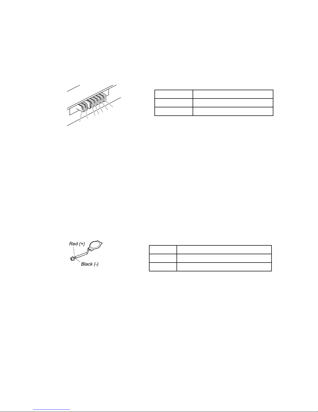
1.Poweroffthecomputer.
2.Removethebatterypackandmeasurethevoltagebetweenbatteryterminals1(+)and7(-).Seethe
followinggure:
Terminal
Voltage(Vdc)
1,2+0to+12.6
6,7
Ground(-)
1(+)
2(+)
3
4
5
6(-)
7(-)
3.Ifthevoltageislessthan+11.0Vdc,thebatterypackhasbeendischarged.
Ifthevoltageisstilllessthan+11.0Vdcafterrecharging,replacethebatterypack.
4.Ifthevoltageismorethan+11.0Vdc,measuretheresistancebetweenbatteryterminals5and7.
Theresistancemustbe4to30KΩ.Iftheresistanceisnotcorrect,replacethebatterypack.Ifthe
resistanceiscorrect,replacethesystemboard.
Checkingthecoin-cellbattery
Dothefollowing:
1.Poweroffthecomputer,andunplugtheacpoweradapterfromit.
2.T urnthecomputerupsidedown.
3.Removethebatterypack(see“1020Batterypack”onpage65).
4.Removethecion-cellbattery(see“1100Coin-cellbattery”onpage74).
5.Measurethevoltageofthecoin-cellbattery.Seethefollowinggure.
Wire
Voltage(Vdc)
Red+2.5to+3.2
Black
Ground
•Ifthevoltageiscorrect,replacethesystemboard.
•Ifthevoltageisnotcorrect,replacethecoin-cellbattery.
•Ifthecoin-cellbatterydischargesquicklyafterreplacement,replacethesystemboard.
32HardwareMaintenanceManual
Page 39

Chapter4.Relatedserviceinformation
Thischapterpresentsfollowinginformation:
•“RestoringthefactorycontentsbyusingtheproductRecoveryDiscSet”onpage33
•“UsingtheWindowsrecoveryprogramsontheWindows8operatingsystem”onpage34
•“Passwords”onpage36
•“Powermanagement”onpage38
•“Symptom-to-FRUindex”onpage39
ServiceWebsite:
Whenthelatestmaintenancedisketteandthesystemprogramservicediskettebecomeavailable,they
willbepostedonhttp://www.lenovo.com/support.
RestoringthefactorycontentsbyusingtheproductRecoveryDiscSet
Whenthemainstoragedeviceisreplacedbecauseofafailure,noproductrecoveryprogramisonthenew
drive.Inthiscase,thecustomermustusetheRecoveryDiscSettorecoverthetablet.OrdertheRecovery
DiscSetandthedriveatthesametimesothatthecustomercanrestorethetablettothefactorydefault
settingsbyusingtheRecoveryDiscSetafterthenewdriveisinstalled.Forinformationaboutwhichdiscsto
order,goto:
http://www.lenovo.com/serviceparts-lookup
Dependingonthemodel,thenumberofrecoverydiscsincludedintheRecoveryDiscSetdiffers.Torestore
thefactorycontentsbyusingtheproductRecoveryDiscSet,dothefollowing:
Notes:
•Duringtherecoveryprocess,alldataonthedrivewillbedeleted.Ifpossible,copyanyimportantdata
orpersonallesthatyouwanttokeepontoremovablemediaoranetworkdrivebeforeyoustartthe
recoveryprocess.
•Therecoveryprocesstakesonetotwohourstocomplete.Thelengthoftimedependsonthemethodyou
use.IfyouuseproductRecoveryDiscSet,therecoveryprocesstakesabouttwohours.
1.ConnectanexternalCD/DVDdrive.
2.MaketheCD/DVDdrivetherststartupdeviceinthestartupsequenceusingthefollowingprocedure:
a.OpentheThinkPadSetupprogramandselectStartup➙Boot.
b.SelecttheCD/DVDdriveasthe1stBootDevice.
3.InsertthebootablerecoverydiscintotheCD/DVDdrive.
4.StartthecomputerfromtheexternalCD/DVDdrive.
5.Whenpromoted,selectyourlanguageandclickNext.
6.Readthelicenseandacceptthetermsandconditions.Thenfollowtheinstructionsonthescreen.
7.IftheRecoveryDiscSetcontainsaSupplementalRecoveryDisc,insertitwhenpromptedandclickYes.
Note:NotallRecoveryDiscSetscomewithaSupplementalRecoveryDisc.IfthereisaSupplemental
RecoveryDisc,itwillbeclearlymarkedassuch.
8.Whenallofthedatahasbeencopiedfromthelastdiscinthesetandhasbeenprocessed,remove
theexternalCD/DVDdriveandrestartthecomputer.Followtheinstructionsonthescreentonish
therecovery.
Note:Therestoftherecoveryprocessisfullyautomatedandnoactionfromyouisrequired.The
computerwillrestartintotheMicrosoftWindowsdesktopseveraltimesandyoumightexperience
periodswhennoactivityisapparentonthescreenforseveralminutesatatime.Thisisnormal.
©CopyrightLenovo2013
33
Page 40

9.Whentherecoveryprocesscompletes,theWelcometoMicrosoftWindowsscreenisdisplayed.Follow
theinstructionsonthescreentocompletetheWindowssetup.
10.AfteryouhavecompletedtheWindowssetup,youmightwanttorestoretheoriginalstartupsequence.
StarttheThinkPadSetupprogramandthenpressF9torestorethedefaultsettings.PressF10tosave
changesandexittheThinkPadSetupprogram.
Note:Afterrestoringadrivetothefactorydefaultsettings,youmightneedtoreinstallsomedevicedrivers.
UsingtheWindowsrecoveryprogramsontheWindows8operating
system
ThissectionprovidesinformationabouttherecoverysolutionsfortheWindows8operatingsystem.
AWindowsrecoveryimageispreinstalledintherecoverypartitiononyourcomputer.TheWindowsrecovery
imageenablesyoutorefreshyourcomputer,orresetyourcomputertothefactorydefaultsettings.
YoucancreaterecoverymediaasbackupsorreplacementfortheWindowsrecoveryimage.Withthe
recoverymedia,youcantroubleshootandxtheproblemsonyourcomputerevenifyoucannotstartthe
Windows8operatingsystem.Itisrecommendedthatyoucreaterecoverymediaasearlyaspossible.For
moreinformation,see“Creatingandusingrecoverymedia”onpage35
.
Refreshingyourcomputer
Ifyourcomputerdoesnotperformwellandtheproblemmightbecausedbyarecentlyinstalledprogram,
youcanrefreshyourcomputerwithoutlosingyourpersonallesorchangingyoursettings.
Attention:Ifyourefreshyourcomputer,theprogramsthatcamewithyourcomputerandtheprogramsthat
youinstalledfromWindowsStorewillbereinstalled,butallotherprogramswillberemoved.
Torefreshyourcomputer,dothefollowing:
1.Moveyourcursortothetop-rightorbottom-rightcornerofthescreentodisplaythecharms.Click
Settings➙ChangePCsettings➙General.
2.IntheRefreshyourPCwithoutaffectingyourlessection,clickGetstarted.
3.Followtheinstructionsonthescreentorefreshyourcomputer.
Resettingyourcomputertothefactorydefaultsettings
Ifyouwanttorecycleyourcomputerorjuststartover,youcanresetyourcomputertothefactorydefault
settings.Resettingthecomputerwillreinstalltheoperatingsystem,reinstallalltheprogramsthatcamewith
yourcomputer,andresetallthesettingstothefactorydefaultsettings.
Attention:Ifyouresetthecomputertothefactorydefaultsettings,allyourpersonallesandsettingswillbe
deleted.Toavoiddataloss,makeabackupcopyofallthedatathatyouwanttokeep.
Toresetyourcomputertothefactorydefaultsettings,dothefollowing:
1.Moveyourcursortothetop-rightorbottom-rightcornerofthescreentodisplaythecharms.Click
Settings➙ChangePCsettings➙General.
2.IntheRemoveeverythingandreinstallWindowssection,clickGetstarted.ThenclickNextto
conrmtheoperation.
3.Dependingonyourneeds,dooneofthefollowing:
•T operformaquickformat,clickJustremovemylestostarttheprocess.Theprocesswilltake
severalminutes.
34HardwareMaintenanceManual
Page 41

•T operformacompleteformat,clickFullycleanthedrivetostarttheprocess.Theprocesswill
takeseveralhours.
4.Followtheinstructionsonthescreentoresetyourcomputertothefactorydefaultsettings.
Usingtheadvancedstartupoptions
Withtheadvancedstartupoptions,youcanchangethermwaresettingsofthecomputer,changethe
startupsettingsoftheWindowsoperatingsystem,startthecomputerfromanexternaldevice,orrestorethe
Windowsoperatingsystemfromasystemimage.
Tousetheadvancedstartupoptions,dothefollowing:
1.Moveyourcursortothetop-rightorbottom-rightcornerofthescreentodisplaythecharms.Click
Settings➙ChangePCsettings➙General.
2.IntheAdvancedstartupsection,clickRestartnow➙Troubleshoot➙Advancedoptions.
3.Selectadesiredstartupoption,thenfollowtheinstructionsonthescreen.
RecoveringyouroperatingsystemifWindows8failstostart
TheWindowsrecoveryenvironmentonyourcomputeriscapableofoperatingindependentlyfromthe
Windows8operatingsystem.Thisenablesyoutorecoverorrepairtheoperatingsystemevenifthe
Windows8operatingsystemfailstostart.
Aftertwoconsecutivefailedbootattempts,theWindowsrecoveryenvironmentstartsautomatically.Then
youcanchooserepairandrecoveryoptionsbyfollowingtheinstructionsonthescreen.
Note:Ensurethatyourcomputerisconnectedtoacpowerduringtherecoveryprocess.
Creatingandusingrecoverymedia
YoucancreaterecoverymediaasbackupsfortheWindowsrecoveryenvironmentandtheWindows
recoveryimage.Ifyoucannotstartthecomputer,youcanuserecoverymediatotroubleshootandxthe
problemsonyourcomputer.
Itisrecommendedthatyoucreaterecoverymediaasearlyaspossible.Onceyoucreaterecoverymedia,
keeptheminasafeplaceanddonotusethemtostoreotherdata.
Creatingrecoverymedia
Tocreaterecoverymedia,youneedaUSBdrivewithatleast8GBofstorage.TherequiredUSBcapacity
dependsonthesizeoftherecoveryimage.
Attention:CreatingrecoverymediawilldeleteanythingstoredontheUSBdrive.T oavoiddataloss,makea
backupcopyofallthedatathatyouwanttokeep.
Tocreaterecoverymedia,dothefollowing:
Note:Ensurethatyourcomputerisconnectedtoacpower.
1.Moveyourcursortothetop-rightorbottom-rightcornerofthescreentodisplaythecharms,and
clickSearch.
2.T yperecoveryintheSearcheldandclickSettings.ThenclickCreatearecoverydrive.
3.ClickY esintheUserAccountControlwindowtoallowtheRecoveryMediaCreatorprogramtostart.
4.EnsurethatyouselecttheCopytherecoverypartitionfromthePCtotherecoverydrive.option.
ThenclickNext.
Chapter4.Relatedserviceinformation35
Page 42

Important:IfyoucleartheCopytherecoverypartitionfromthePCtotherecoverydrive.option,
youwillcreaterecoverymediawithouttherecoverypartitioncontent.Y oustillcanstartthecomputer
fromtherecoverymedia,butyoumightbeunabletorecoveryourcomputeriftherecoverypartitionon
yourcomputerisdamaged.
5.ConnectaproperUSBdrivethenclickNext.
6.ClickCreateintheRecoveryDrivewindow.Thecreationoftherecoverymediastarts.
7.Whenthecreationoftherecoverymedianishes,dooneofthefollowing:
•T okeeptherecoverypartitiononyourcomputer,clickFinish.
•T odeletetherecoverypartitiononyourcomputer,clickDeletetherecoverypartition.
Attention:Ifyoudeletetherecoverypartitiononyourcomputer,dokeeptherecoverymediaina
safeplace.TheWindowsrecoveryimagewillnotbestoredinyourcomputeranymore,andyouwill
needtherecoverymediatorefreshorresetyourcomputer.
8.RemovetheUSBdrive.Therecoverymediaarecreatedsuccessfully.
Usingrecoverymedia
Ifyoucannotstartyourcomputer,orifyoucannotstarttheWindowsrecoveryimageonyourcomputer,use
recoverymediatorecoveryourcomputer.
Touserecoverymedia,dothefollowing:
Note:Ensurethatyourcomputerisconnectedtoacpower.
1.T urnonorrestartthecomputer.BeforetheWindowsoperatingsystemstarts,repeatedlypresstheF12
key.TheBootMenuwindowopens.
2.Selecttherecoverydriveasthebootdevice.
3.Selectapreferredlanguageandthenselectapreferredkeyboardlayout.
4.ClickT roubleshoottodisplaytheoptionalrecoverysolutions.
5.Selectacorrespondingrecoverysolutionaccordingtoyoursituation.Forexample,selectResetyour
PCifyouwanttoresetyourcomputertothefactorydefaultsettings.
FormoreinformationabouttherecoverysolutionsprovidedbytheWindows8operatingsystem,goto:
http://go.microsoft.com/fwlink/?LinkID=263800
Passwords
AsmanyasthreepasswordsmightbeneededforaThinkPadnotebookcomputer:thepower-onpassword,
theharddiskpassword,andthesupervisorpassword.
Ifanyofthesepasswordshasbeenset,apromptforitwillbedisplayedonthescreenwheneverthe
computeristurnedon.Thecomputerdoesnotstartuntilthepasswordisentered.
Note:Ifonlyasupervisorpasswordisset,thepasswordpromptwillnotbedisplayedwhentheoperating
systemisstarted.
Power-onpassword
Apower-onpasswordprotectsthesystemfrombeingturnedonbyanunauthorizedperson.Thepassword
mustbeenteredbeforetheoperatingsystemcanbestarted.Forinstructionsonhowtoremovethe
power-onpassword,see“Howtoremovethepower-onpassword”onpage37
.
36HardwareMaintenanceManual
Page 43

Harddiskpassword
Therearetwoharddiskpasswords:
•Userharddiskpassword-fortheuser
•Masterharddiskpassword-forthesystemadministrator,whocanuseittogetaccesstotheharddisk
eveniftheuserhaschangedtheuserharddiskpassword.
Note:Therearetwomodesfortheharddiskpassword:UseronlyandMaster+User.TheMaster+User
moderequirestwoharddiskpasswords;thesystemadministratorentersbothinthesameoperation.The
systemadministratorthenprovidestheuserharddiskpasswordtothesystemuser.
Attention:Iftheuserharddiskpasswordhasbeenforgotten,checkwhetheramasterharddiskpassword
hasbeenset.Ifamasterharddiskpasswordhasbeenset,itcanbeusedtoaccesstheharddiskdrive.If
nomasterharddiskpasswordisavailable,neitherLenovonorLenovoauthorizedservicetechniciansprovide
anyservicestoreseteithertheuserharddiskpasswordorthemasterharddiskpassword,ortorecoverdata
fromtheharddiskdrive.Theharddiskdrivecanbereplacedforascheduledfee.
Forinstructionsonhowtoremovetheharddiskpassword,see“Howtoremovetheharddiskpassword”
onpage38
.
Supervisorpassword
AsupervisorpasswordprotectsthesysteminformationstoredintheThinkPadSetupprogram.Theuser
mustenterthesupervisorpasswordinordertogetaccesstotheThinkPadSetupprogramandchangethe
systemconguration.
Attention:Ifthesupervisorpasswordhasbeenforgottenandcannotbemadeavailabletotheservice
technician,thereisnoserviceproceduretoresetthepassword.Thesystemboardmustbereplacedfor
ascheduledfee.
Howtoremovethepower-onpassword
Toremovethepower-onpassword,dooneofthefollowing:
Ifnosupervisorpasswordhasbeenset,dothefollowingtoremovethepower-onpassword:
1.T urnoffthecomputer.
2.Removethebatterypack.Forinstructionsonhowtoremovethebatterypack,see“1020Battery
pack”onpage65.
3.Removethecoin-cellbattery.Forinstructionsonhowtoremovethecoin-cellbattery,see“1100
Coin-cellbattery”onpage74.
4.T urnonthecomputerandwaituntilthepower-onself-test(POST)ends.AfterthePOSTends,the
passwordpromptwillnotbedisplayed.Thepower-onpasswordhasbeenremoved.
5.Reinstallthecoin-cellbatteryandthebatterypack.
Ifasupervisorpasswordhasbeensetandisknowntotheservicetechnician,dothefollowingtoremove
thepower-onpassword:
1.T urnonthecomputer.
2.Whenthelogoscreenisdisplayed,immediatelypressF1.
3.T ypethesupervisorpasswordtoentertheThinkPadSetupprogram.
4.SelectSecurity.
5.SelectPassword.
6.SelectPower-OnPassword.
Chapter4.Relatedserviceinformation37
Page 44

7.T ypethecurrentsupervisorpasswordintheEnterCurrentPasswordeld.Then,leavetheEnter
NewPasswordeldblank,andpressEntertwice.
8.IntheChangeshavebeensavedwindow,pressEnter.
9.PressFn+F10tosavechangesandexittheThinkPadSetupprogram.
Howtoremovetheharddiskpassword
Attention:IfUseronlymodeisselectedandtheuserharddiskpasswordhasbeenforgottenandcannotbe
madeavailabletotheservicetechnician,neitherLenovonorLenovoauthorizedservicetechniciansprovide
anyservicestoresettheuserharddiskpassword,ortorecoverdatafromtheharddiskdrive.Thehard
diskdrivecanbereplacedforascheduledfee.T oputthesystembacktooperationalstatus,theonly
LenovoandLenovo-authorizedservicesolutionwouldbetoreplacetheharddiskdriveorsolid-statedrive
withascheduledfee.
Toremoveauserharddiskpasswordthathasbeenforgotten,whenthesupervisorpasswordandthemaster
harddiskpasswordareknown,dothefollowing:
1.T urnonthecomputer.
2.Whenthelogoscreenisdisplayed,immediatelypressF1toentertheThinkPadSetupprogram.
3.SelectSecurity.
4.SelectPassword.
5.SelectHard-diskxpasswordwherexistheletteroftheharddiskdrive.Apop-upwindowopens.
6.SelectMasterHDP,whereHDPstandsforharddiskpassword.
7.T ypethecurrentmasterharddiskpasswordintheEnterCurrentPasswordeld.Then,leavetheEnter
NewPasswordeldblank,andpressEntertwice.
8.PressFn+F10tosavechangesandexittheThinkPadSetupprogram.Theuserharddiskpasswordand
themasterharddiskpasswordhavebeenremoved.
Powermanagement
Toreducepowerconsumption,thecomputerhasthreepowermanagementmodes:screenblank,sleep,
andhibernation.
Screenblankmode(fortheWindows7operatingsystemonly)
Ifthetimesetonthe“Turnoffmonitor”timerintheoperatingsystemexpires,theLCDbacklightturnsoff.
Toputthecomputerintoscreenblankmode,dothefollowing:
1.Right-clickthebatterygaugeinthetaskbar.
2.SelectPoweroffdisplay(keepcurrentpowerplan).
Toendscreenblankmodeandresumenormaloperation,pressanykey.
Sleepmode
Whenthecomputerenterssleepmode,thefollowingeventsoccurinadditiontowhatoccursinscreen
blankmode:
•TheLCDispoweredoff.
•Theharddiskdriveorsolid-statedriveispoweredoff.
•Themicroprocessorstops.
Toentersleepmode,dooneofthefollowing:
38HardwareMaintenanceManual
Page 45

•ForWindows7:ClickthearrowbesidetheShutdownicon,andthenselectSleep.T oreturnfrom
sleepmode,pressanykey.
•ForWindows8:Movethecursortothebottom-rightcornerofthescreentodisplaythecharms.Then
clickSettings➙Power➙Sleep.
Incertaincircumstances,thecomputergoesintosleepmodeautomatically:
•Afteraperiodofinactivityspeciedinpowerplansettings
•Whenthebatterypowerislow
Tocausethecomputertoreturnfromsleepmodeandresumeoperation,dooneofthefollowing:
•Pressanykey.
•OpentheLCDcover.
•T urnonthepowerbutton.
Also,ineitherofthefollowingevents,thecomputerautomaticallyreturnsfromsleepmodeandresumes
operation:
•Theringindicator(RI)issignaledbyaserialdeviceoraPCCarddevice.
•Thetimesetontheresumetimerelapses.
Note:Thecomputerdoesnotacceptanyinputimmediatelyafteritenterssleepmode.Waitafew
secondsbeforetakinganyactiontoreenteroperationmode.
Hibernationmode
Inhibernationmode,thefollowingoccurs:
•Thesystemstatus,random-accessmemory(RAM),videorandom-accessmemory(VRAM),andsetup
dataarestoredontheharddiskdriveorsolid-statedrive.
•Thesystemispoweredoff.
Note:Ifthecomputerentersthehibernationmodewhileitisconnectedtothedock,donotdisconnectit
beforeresumingnormaloperation.Ifyoudodisconnectitandthentrytoresumenormaloperation,youwill
getanerrormessage,andyouwillhavetorestartthesystem.
Ifyouhavedenedoneofthefollowingactionsastheeventthatcausesthesystemtogointohibernation
mode,performthataction.
•Closingthelid.
•Pressingthepowerbutton.
Also,thecomputergoesintohibernationmodeautomaticallyafteraperiodofinactivityspeciedinpower
plansettings
Whenthepoweristurnedon,thecomputerreturnsfromhibernationmodeandresumesoperation.The
hibernationleinthebootrecordontheharddiskdriveorsolid-statedriveisread,andsystemstatusis
restoredfromtheharddiskdriveorsolid-statedrive.
Symptom-to-FRUindex
Thissectioncontainsfollowinginformation:
•“Numericerrorcodes”onpage40
•“Errormessages”onpage42
•“No-beepsymptoms”onpage42
•“LCD-relatedsymptoms”onpage43
Chapter4.Relatedserviceinformation39
Page 46

•“Intermittentproblems”onpage43
•“Undeterminedproblems”onpage43
Thesymptom-to-FRUindexinthissectionlistssymptomsanderrorsandtheirpossiblecauses.Themost
likelycauseislistedrst,inboldfacetype.
Note:DotheFRUreplacementorotheractionsinthesequenceshowninthecolumnheaded“FRUor
action,insequence.”IfreplacingaFRUdoesnotsolvetheproblem,puttheoriginalpartbackinthe
computer.DonotreplaceanondefectiveFRU.
Thisindexcanalsohelpyoudetermine,duringregularservicing,whatFRUsarelikelytoneedtobe
replacednext.
AnumericerrorisdisplayedforeacherrordetectedinPOSTorsystemoperation.Inthedisplays,ncan
beanynumber.
Ifnonumericcodeisdisplayed,checkthenarrativedescriptionsofsymptoms.Ifthesymptomisnot
describedthere,goto“Intermittentproblems”onpage43
.
Note:ForadevicenotsupportedbydiagnosticcodesintheThinkPadnotebooks,seethemanualfor
thatdevice.
Numericerrorcodes
Table2.Numericerrorcodes
Symptomorerror(beeps,ifany)
FRUoraction,insequence
0177
BadSVPdata,stopPOSTtask—Thechecksumofthe
supervisorpasswordintheEEPROMisnotcorrect.
Replacethesystemboard.
0183
BadCRCofSecuritySettingsinEFIVariable.Enterthe
ThinkPadSetupprogram.–ThechecksumoftheSecurity
settingsintheEFIVariableisnotcorrect.
1.RuntheThinkPadSetupprogram.Thesettings
willbecorrectedautomatically .Thensavethe
currentsettingsbypressingFn+F10.
2.Replacethesystemboard.
0187
EAIAdataaccesserror-TheaccesstoEEPROMisfailed.
Replacethesystemboard.
0188
InvalidRFIDSerializationInformationArea.
Replacethesystemboard.
0189
InvalidRFIDcongurationinformationarea-TheEEPROM
checksumisnotcorrect.
Replacethesystemboard.
0190
Criticallow-batteryerror
1.Chargethebatterypack.
2.Replacethebatterypack.
0191
SystemSecurity-InvalidRemoteChangerequested.
1.RuntheThinkPadSetupprogram,andthensave
currentsettingbypressingFn+F10.
2.Replacethesystemboard.
0199
SystemSecurity-Securitypasswordretrycount
exceeded.
1.RuntheThinkPadSetupprogram.Theretrycount
willbereset.Thensavethecurrentsettingsby
pressingFn+F10.
2.Replacethesystemboard.
40HardwareMaintenanceManual
Page 47

Table2.Numericerrorcodes(continued)
Symptomorerror(beeps,ifany)
FRUoraction,insequence
0251
SystemCMOSchecksumbad-Defaultconguration
used.
1.Chargethecoin-cellbatteryformorethan8hours
byconnectingtheacpoweradapter.
2.Replacethecoin-cellbatteryandruntheThinkPad
Setupprogramtoresetthetimeanddate.
0253
EFIVariableBlockDatawasdestroyed.
1.RunThinkPadSetuptorecongurethesettings.
2.Replacethesystemboard.
0271
Real-TimeClockError.CheckDateandTimesettings.
1.RunThinkPadSetuptoresetthetimeanddate
2.Replacethecoin-cellbatteryandruntheThinkPad
Setupprogramtoresetthetimeanddate.
1802
Unauthorizednetworkcardispluggedin-T urnoffand
removethenetworkcard.
1.Removethenetworkcard.
2.Replacethesystemboard.
1820
Morethanoneexternalngerprintreaderisattached.
Poweroffandremoveallbutthereaderthatyousetup
withinyourmainoperatingsystem.
Removeallbutthereaderthatyousetupforthe
authentication
2000
ThinkVantageActiveProtectionsensordiagnosticsfailed.
Havethecomputerserviced.
2100
DetectionerroronHDD0(MainHDD)
1.Reseattheharddiskdrive.
2.Replacethemainharddiskdrive.
3.Replacethesystemboard.
2101
DetectionerroronHDD1(UltrabayHDD)
1.Reseattheharddiskdrive.
2.ReplacetheUltrabay
®
harddiskdrive.
3.Replacethesystemboard.
2102
DetectionerroronHDD2(MiniSAT A)
1.Reseatthe(MiniSerialAdvancedT echnology
Attachment)SA T Adevice.
2.ReplacetheminiSATAdevice.
3.Replacethesystemboard.
2110
ReaderroronHDD0(MainHDD)
1.Reseattheharddiskdrive.
2.Replacethemainharddiskdrive.
3.Replacethesystemboard.
2111
ReaderroronHDD1(UltrabayHDD)
1.Reseattheharddiskdrive.
2.ReplacetheUltrabayharddiskdrive.
3.Replacethesystemboard.
2112
ReaderroronHDD2(MiniSA TA)
1.ReseattheMiniSATAdevice.
2.ReplacetheminiSATAdevice.
3.Replacethesystemboard.
2200
MachineT ypeandSerialNumberareinvalid.
Replacethesystemboard.
2201
MachineUUIDisinvalid
Replacethesystemboard.
Chapter4.Relatedserviceinformation41
Page 48

Errormessages
Table3.Errormessages
Symptomorerror(beeps,ifany)
FRUoraction,insequence
Fanerror.1.Replacethefan.
2.Applythermalgrease.
3.Replacethesystemboard.
Thermalsensingerror.Replacethesystemboard.
Thebatteryinstalledisnotsupportedbythissystem
andwillnotcharge.Pleasereplacethebatterywiththe
correctLenovobatteryforthissystem.PresstheESC
keytocontinue.
Replacethebatterypack.
Thissystemdoesnotsupportbatteriesthatarenot
genuineLenovo-madeorauthorized.Thesystemwill
continuetoboot,butmaynotchargeunauthorized
batteries.
Attention:Lenovohasnoresponsibilityforthe
performanceorsafetyofunauthorizedbatteries,and
providesnowarrantiesforfailuresordamagearisingout
oftheiruse.
Replacethebatterypack.
Beepsymptoms
Table4.Beepsymptoms
Symptomorerror
FRUoraction,insequence
Oneshortbeep,pause,threeshortbeeps,pause,three
moreshortbeeps,pause,andoneshortbeep
1.Replacethememorymodule.
2.Replacethesystemboard.
Threeshortbeeps,pause,oneshortbeep,pause,one
moreshortbeep,pause,andthreeshortbeeps
RemovethedevicefromExpressCardslot.
Onelongandtwoshortbeeps
Replacethesystemboard.
FiveshortbeepsReplacethesystemboard.
No-beepsymptoms
Table5.No-beepsymptoms
Symptomorerror
FRUoraction,insequence
Nobeep,power-onindicatoron,LCDblank,andno
POST.
1.Ensurethateveryconnectorisconnectedtightly
andcorrectly.
2.Reseatmemorymodule.
3.Replacethesystemboard.
Nobeep,power-onindicatoron,andLCDblankduring
POST.
1.Reseatmemorymodule.
2.Replacethesystemboard.
Thepower-onpasswordpromptappears.Apower-onpasswordorasupervisorpasswordisset.
TypethepasswordandpressEnter.
Thehard-diskpasswordpromptappears.Ahard-diskpasswordisset.T ypethepasswordand
pressEnter.
42HardwareMaintenanceManual
Page 49

LCD-relatedsymptoms
Important:TheTFTLCDforthenotebookcomputercontainsmanythin-lmtransistors(TFT s).The
presenceofasmallnumberofdotsthataremissing,discolored,oralwayslightedischaracteristicofTFT
LCDtechnology,butexcessivepixelproblemscancauseviewingconcerns.
IftheLCDyouareservicinghastwoorlessvisibledefectivepixels,itshouldnotbeconsideredfaulty.
However,iftheLCDhasthreeormorevisibledefectivepixels,itwillbedeemedasdefectivebyLenovoand
itshouldbereplaced.
Notes:
•ThispolicyappliestoallThinkPadNotebookspurchasedon1January,2008orlater.
•LenovowillnotprovidewarrantyreplacementiftheLCDiswithinspecicationsbecausewecannot
guaranteethatanyreplacementLCDwillhavezeropixeldefects.
•OnepixelconsistsofR,G,Bsub-pixels.
Table6.LCD-relatedsymptoms
Symptomorerror
FRUoraction,insequence
Nobeep,power-onindicatoron,andablankLCDduring
POST.
Replacethesystemboard.
•LCDbacklightnotworking.
•LCDtoodark.
•LCDbrightnesscannotbeadjusted.
•LCDcontrastcannotbeadjusted.
1.ReseattheLCDconnectors.
2.ReplacetheLCDassembly.
3.Replacethesystemboard.
•LCDscreenunreadable.
•Charactersmissingpixels.
•Screenabnormal.
•Wrongcolordisplayed.
1.Seeimportantnotefor“LCD-relatedsymptoms. ”
2.ReseatallLCDconnectors.
3.ReplacetheLCDassembly.
4.Replacethesystemboard.
HorizontalorverticallinesdisplayedonLCD.ReplacetheLCDassembly.
Intermittentproblems
Intermittentsystemhangproblemscanbeduetoavarietyofcausesthathavenothingtodowithahardware
defect,suchascosmicradiation,ESD,orsoftwareerrors.FRUreplacementshouldbeconsideredonly
whenaproblemrecurs.
Whenanalyzinganintermittentproblem,dothefollowing:
1.Runthediagnostictestforthesystemboardinloopmodeatleast10times.
2.Ifnoerrorisdetected,donotreplaceanyFRUs.
3.Ifanyerrorisdetected,replacetheFRUshownbytheFRUcode.Rerunthetesttoverifythatno
moreerrorsexist.
Undeterminedproblems
Ifthediagnostictestsdidnotidentifythedevicethathasfailed,ifwrongdevicesareinstalled,orifthe
systemsimplyisnotoperating,followtheseprocedurestoisolatethefailingFRU(donotisolateFRUs
thathavenodefects).
Verifythatallattacheddevicesaresupportedbythecomputer.
Verifythatthepowersupplybeingusedatthetimeofthefailureisoperatingcorrectly.(See“Powersystem
checkout”onpage30
)
Chapter4.Relatedserviceinformation43
Page 50

1.T urnoffthecomputer.
2.VisuallycheckeachFRUfordamage.ReplaceanydamagedFRU.
3.Removeordisconnectallofthefollowingdevices:
a.Non- ThinkPaddevices
b.Devicesattachedtothedock
c.Printer,mouse,andotherexternaldevices
d.Batterypack
e.Harddiskdriveorsolid-statedrive
f.Externaldiskettedriveoropticaldrive
g.Memorymodule
h.Opticaldiskordisketteintheinternaldrive
i.PCCards
4.T urnonthecomputer.
5.Determinewhethertheproblemhasbeensolved.
6.Iftheproblemdoesnotrecur,reconnecttheremoveddevicesoneatatimeuntilyoundthefailingFRU.
7.Iftheproblemremains,replacethefollowingFRUsoneatatime(donotreplaceanondefectiveFRU):
a.Systemboard
b.LCDassembly
44HardwareMaintenanceManual
Page 51
Chapter5.Statusindicators
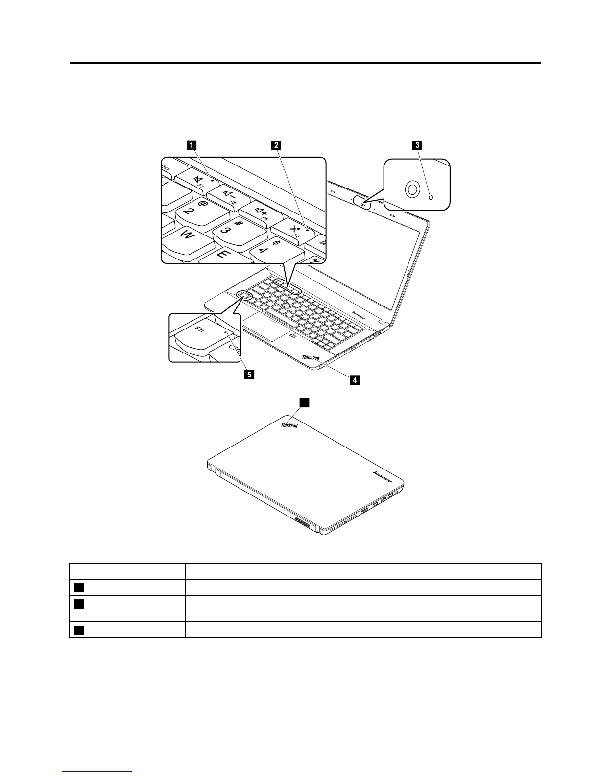
Thischapterpresentsthesystem-statusindicatorsthatshowthestatusofthecomputer.
4
2
3
5
6
Table7.Statusindicators
IndicatorMeaning
1Speaker-muterindicatorOn:Thespeakersaremuted.
2Microphone-mute
indicator
On:Themicrophonesaremuted.
3CamerastatusindicatorOn:Thecameraisinuse.
©CopyrightLenovo2013
45
Page 52

Table7.Statusindicators(continued)
IndicatorMeaning
46System-status
indicator
Blinkingthreetimes:Thecomputerisinitiallyconnectedtopower.
On:Thecomputerisinuse.
Off:Thecomputerisofforinhibernationmode.
Slowblinking:Thecomputerisinsleepmode.
Fastblinking:Thecomputerisenteringhibernationmode.
5FnLockindicator
Off:TheFnLockfunctionisdisabled.Toinitiatethespecialfunctionofeachkey,press
thefunctionkeysdirectly.ToinputF1-F12,presstheFnkeyandthecorresponding
functionkey.
On(legacymode):TheFnLockfunctionisenabled.Toinitiatethespecialfunctionof
eachkey,presstheFnkeyandthecorrespondingfunctionkey.T oinputF1-F12,press
thefunctionkeysdirectly.
46HardwareMaintenanceManual
Page 53
Chapter6.Specialkeys
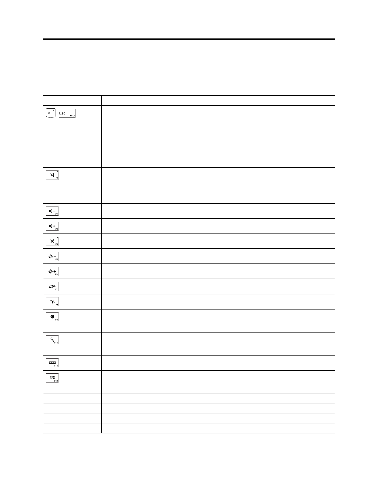
Thefollowingtabledescribesthefunctionsoffunctionkeysandkeycombinations.
Table8.Specialkeys
Specialkey
Description
+
EnablesordisablestheFnLockfunction.
WhentheFnLockfunctionisdisabled:TheFnLockindicatorisoff.T oinitiatethespecial
functionofeachkey,pressthefunctionkeysdirectly.T oinputF1-F12,presstheFnkey
andthecorrespondingfunctionkey.
WhentheFnLockfunctionisenabled:TheFnLockindicatorturnson.Toinitiatethe
specialfunctionofeachkey,presstheFnkeyandthecorrespondingfunctionkey.Toinput
F1-F12,pressthefunctionkeysdirectly.
Mutesorunmutesthespeakers.
Ifyoumutethesoundandturnoffyourcomputer,thesoundwillremainmutedwhenyouturn
onyourcomputeragain.Toturnonthesound,pressF1,F2,orF3.
Decreasesthespeakervolume.
Increasesthespeakervolume.
Mutesorunmutesthemicrophones.
Darkensthedisplay.
Brightensthedisplay.
Switchesthedisplayoutputlocation.
Enablesordisablesthebuilt-inwirelessnetworkingfeatures.
ForWindows8:OpenstheSettingscharm.
ForWindows7:OpensControlPanel.
ForWindows8:OpenstheSearchcharm.
ForWindows7:OpensWindowsSearch.
Viewstheprogramsthatyouhaveopened.
ForWindows8:Viewsalltheprograms.
ForWindows7:OpensComputer.
Fn+B
HasthesamefunctionastheBreakkeyonaconventionalkeyboard.
Fn+P
HasthesamefunctionasthePausekeyonaconventionalkeyboard.
Fn+SHasthesamefunctionastheSysRqkeyonaconventionalkeyboard.
Fn+K
HasthesamefunctionastheScrLKkeyonaconventionalkeyboard.
©CopyrightLenovo2013
47
Page 54

48HardwareMaintenanceManual
Page 55
Chapter7.Locations
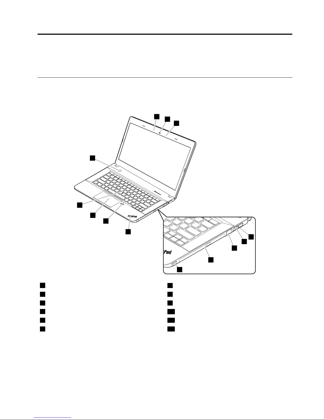
Thischapterintroducesthelocationsofthehardwarecomponentsonyourcomputer.
Locatingcomputercontrols,connectors,andindicators
Thistopicintroducesthelocationsofthecomputercontrols,connectors,andindicators.
Frontview
1
1
2
3
4
5
6
7
8
9
10
11
121
1Microphones
7Always-OnUSBconnector
2Camera8System-statusindicator
1
3LenovoOneLinkconnector9Fingerprintreader(onsomemodels)
4acpowerconnector
10ThinkPadtrackpad
5Ethernetconnector11T rackPoint
®
pointingstick
6Opticaldriveoroptical-drivebaybezel
12Powerbutton
1
:Forthedescriptionofthesystem-statusindicator,seeChapter5“Statusindicators”onpage45
.
©CopyrightLenovo2013
49
Page 56
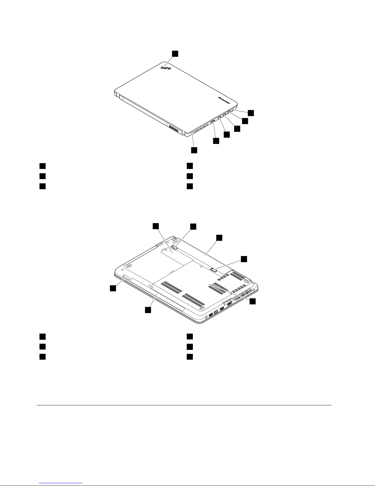
Rearview
1
2
3
4
3
5
6
1System-statusindicator
1
4HDMIport
2Comboaudioconnector5VGAconnector
3USB3.0connectors6Security-lockslot
1
:Forthedescriptionofthesystem-statusindicator,seeChapter5“Statusindicators”onpage45.
Bottomview
3
2
2
1
4
5
6
1Smallbottomcover
1
4Largebottomcover
2
2Batterypacklatches
5Speakers
3Batterypack6Mediacardslot
1
:Thewirelesslocal-area-network(LAN)cardandcoin-cellbatteryarelocatedunderneaththesmall
bottomcover.
2
:Thememorymodules,harddiskdriveorsolid-statedrive,andwirelessWANcardorM.2solid-state
drivearelocatedunderneaththelargebottomcover.
LocatingFRUsandCRUs
Thistopicintroducesthefollowingserviceparts:
•“MajorFRUsandCRUs”onpage52
•“LCDFRUsandCRUs”onpage54
50HardwareMaintenanceManual
Page 57

Notes:
•EachFRUisavailableforalltypesormodels,unlessotherwisespecied.
•CRUstatementforcustomers:
Youcanresolvesomeproblemswithyourproductwithareplacementpartyoucaninstallyourself,calleda
“Customer-replaceableunit”or“CRU. ”SomeCRUsaredesignatedasself-serviceCRUsandothersaredesignated
asoptional-serviceCRUs.Installationofself-serviceCRUsisyourresponsibility.Foroptional-serviceCRUs,you
caneitherinstalltheCRUyourselforyoucanrequestthataServiceProviderinstalltheCRUaccordingtothe
warrantyserviceforyourproduct.IfyouintendoninstallingtheCRU,LenovowillshiptheCRUtoyou.CRU
informationandreplacementinstructionsareshippedwithyourproductandareavailablefromLenovoatanytime
uponrequest.Y oucanndalistofCRUsforyourproductinthisHardwareMaintenanceManual.Anelectronic
versionofthismanualcanbefoundathttp://www.lenovo.com/support.ClickUserGuides&Manualsand
thenfollowtheon-screeninstructionstondthemanualforyourproduct.Y oumightberequiredtoreturnthe
defectiveCRU.Whenreturnisrequired:(1)returninstructions,aprepaidshippinglabel,andacontainerwillbe
includedwiththereplacementCRU;and(2)youmightbechargedforthereplacementCRUifLenovodoesnot
receivethedefectiveCRUwithinthirty(30)daysofyourreceiptofthereplacementCRU.SeeyourLenovoLimited
Warrantydocumentationforfulldetails.
ThinkPadcomputerscontainthefollowingtypesofCRUs:
–Self-serviceCRUs:TheseCRUsunplugorareheldbynomorethantwoscrews.Examplesofthesetypesof
CRUsincludetheacpoweradapter,powercord,batterypack,andharddiskdriveorsolid-statedrive.Other
self-serviceCRUsdependingonproductdesignmightincludethememorymodule,wirelesscard,keyboard,
andpalmrestwithngerprintreaderandtouchpad.
–Optional-serviceCRUs:TheseCRUsareisolatedpartswithinthecomputerthatareconcealedbyanaccess
panelthatistypicallysecuredbymorethantwoscrews.Oncetheaccesspanelisremoved,thespecic
CRUisvisible.
Chapter7.Locations51
Page 58
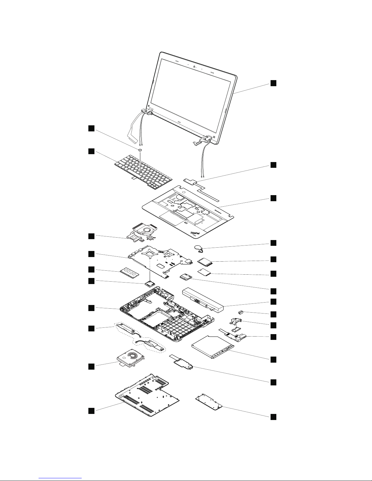
MajorFRUsandCRUs
1
2
3
4
5
5
6
7
10
9
8
11
12
13
14
15
16
17
18
19
20
21
22
23
52HardwareMaintenanceManual
Page 59

Table9.MajorFRUsandCRUs
No.FRUdescription
Self-serviceCRUOptional-serviceCRU
1
LCDunit
NoNo
2
Power-buttoncardNoNo
3
KeyboardbezelassemblyNoNo
4
Coin-cellbattery
YesNo
5
Wireless-WANcardNoYes
5
M.2solid-statedriveNoNo
6
Wireless-LAN/Bluetoothcard
NoYes
7
BatterypackYesNo
8
Lenovo-OneLink-connectorcover
YesNo
9
dc-in/Ethernetcardbracket
NoNo
10
dc-in/Ethernetcard
NoNo
11
Opticaldriveoroptical-drivebaybezel
YesNo
12
Media-card-reader/USBcard
NoNo
13
Smallbottomcover
YesNo
14
LargebottomcoverYesNo
15
Harddiskdrivewithbracketorsolid-statedrive
withbracket
YesNo
16
Speakerassembly
NoNo
17
BasecoverassemblyNoNo
18
MicroprocessorNoNo
19
MemorymoduleYesNo
20
Systemboard
NoNo
21
ThermalmoduleNoNo
22
KeyboardNoYes
23
TrackPointcapYesNo
Chapter7.Locations53
Page 60
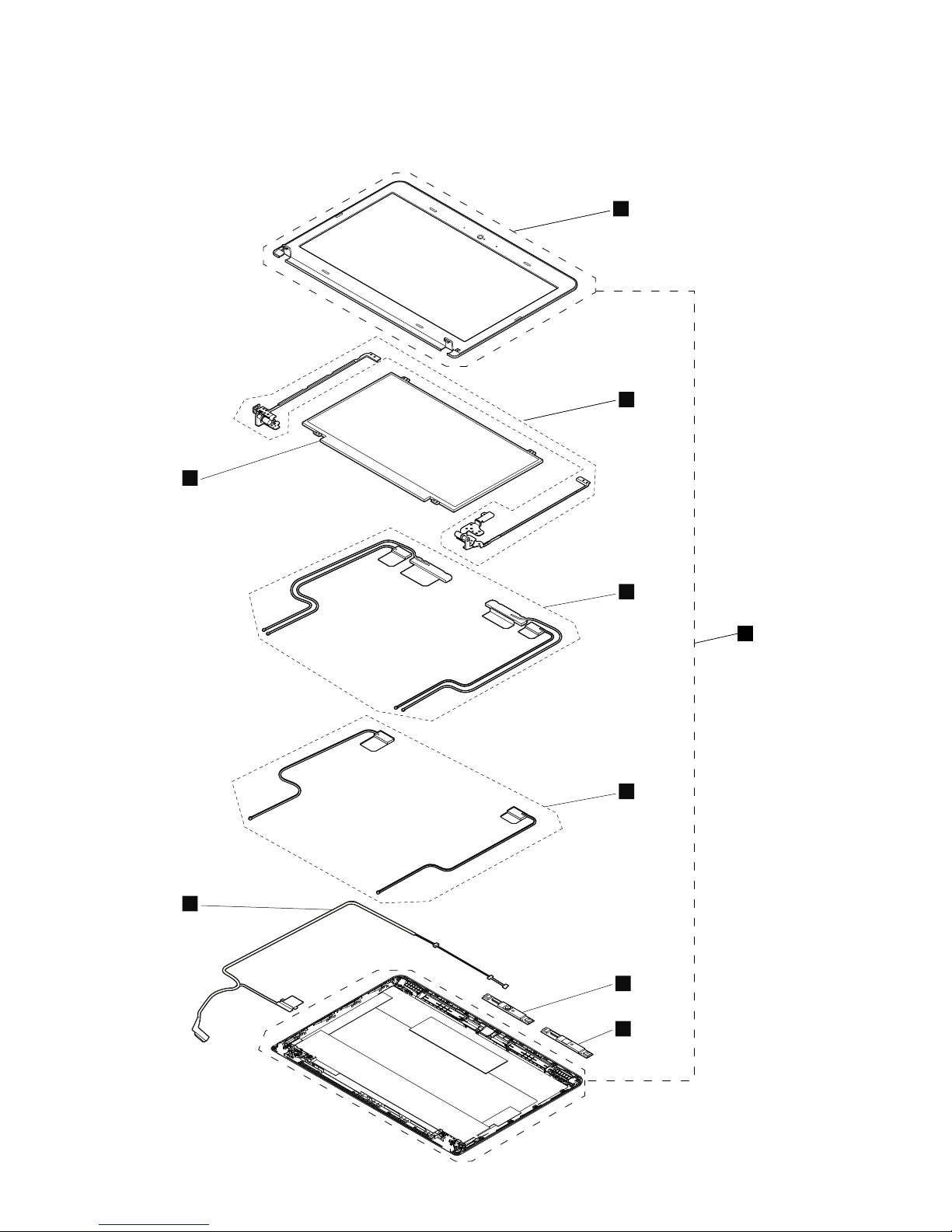
LCDFRUsandCRUs
Formodelswithnon-touchscreen
6
7
2
3
4
4
2
3
3
4
4
6
7
5
11
1
54HardwareMaintenanceManual
Page 61
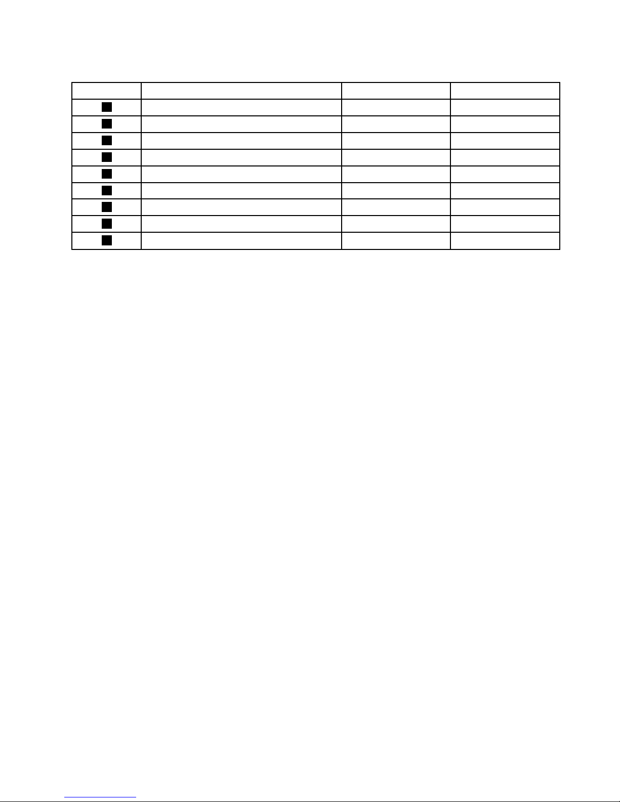
Table10.LCDFRUsandCRUs
No.FRUdescription
Self-serviceCRUOptional-serviceCRU
1
LCDbezel
NoNo
2
LCDhinges
NoNo
3
Wireless-LAN/WANantennaassembly
NoNo
3
Wireless-LANantennaNoNo
4
Camera/microphonemodule
NoNo
4
MicrophonemoduleNoNo
5
LCDcoverkit
NoNo
6
LCDcables
NoNo
7
LCDpanel
NoNo
Chapter7.Locations55
Page 62
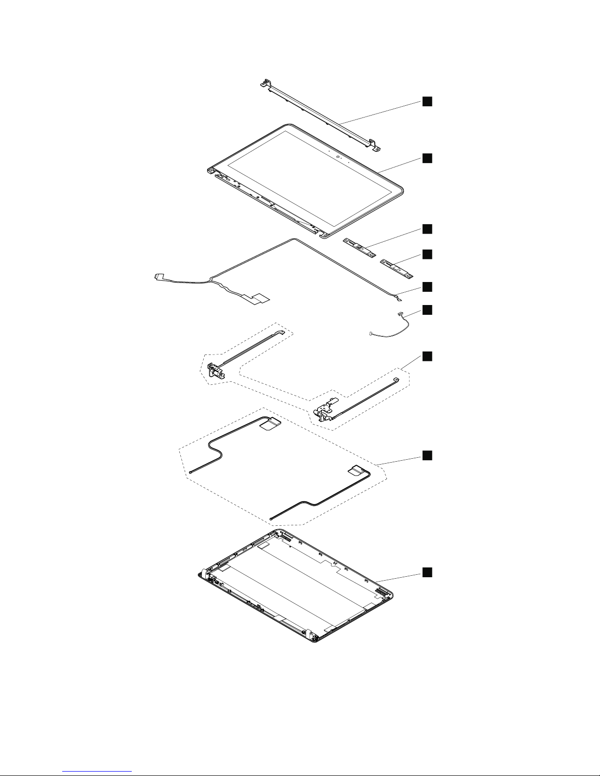
Formodelswithtouchscreen
3
3
1
7
8
3
2
3
4
5
6
56HardwareMaintenanceManual
Page 63
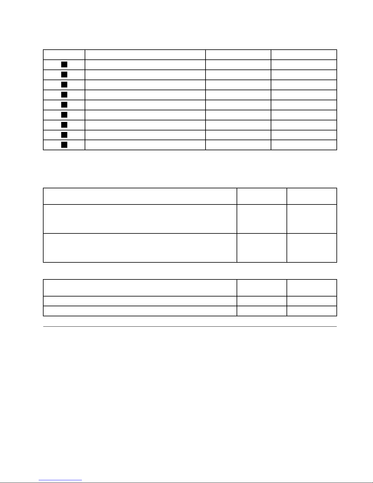
Table11.LCDFRUsandCRUs
No.FRUdescription
Self-serviceCRUOptional-serviceCRU
1
LCD-hingecap
NoNo
2
LCDpanel/screenassembly
NoNo
3
Camera/microphonemodule
NoNo
3
MicrophonemoduleNoNo
4
LCDcable
NoNo
5
LCD-control-cardcable
NoNo
6
LCDhinges
NoNo
7
Wireless-LANantennaNoNo
8
LCDrearcover
NoNo
MiscellaneouskitsandotherFRUs
Miscellaneouskits
FRUdescription
Self-service
CRU
Optionalservice
CRU
Screwkit
•Screwkitfornon-touchscreen
•Screwkitfortouchscreen
NN
Rubberkit
•LCDrubbercap(2)
•LCDscrewmylar(2)
NN
OtherFRUs
FRUdescription
Self-service
CRU
Optionalservice
CRU
acpoweradapterYN
PowercordYN
LookingupFRUinformation
FordetailedFRUinformation,includingpartnumbers,descriptions,andsubstitutionpartnumbers,goto
http://www.lenovo.com/serviceparts-lookup.
Chapter7.Locations57
Page 64

58HardwareMaintenanceManual
Page 65
Chapter8.FRUreplacementnotices
CRUstatementforcustomers:
Youcanresolvesomeproblemswithyourproductwithareplacementpartyoucaninstallyourself,called
a“CustomerReplaceableUnit”or“CRU.”SomeCRUsaredesignatedasself-serviceCRUsandothers
aredesignatedasoptional-serviceCRUs.Installationofself-serviceCRUsisyourresponsibility.For
optional-serviceCRUs,youcaneitherinstalltheCRUyourselforyoucanrequestthataServiceProvider
installtheCRUaccordingtothewarrantyserviceforyourproduct.IfyouintendoninstallingtheCRU,
LenovowillshiptheCRUtoyou.CRUinformationandreplacementinstructionsareshippedwithyour
productandareavailablefromLenovoatanytimeuponrequest.YoucanndalistofCRUsforyour
productinthisHardwareMaintenanceManual.Anelectronicversionofthismanualcanbefoundat
http://www.lenovo.com/support.ClickUserGuides&Manualsandthenfollowtheon-screeninstructions
tondthemanualforyourproduct.Y oumightberequiredtoreturnthedefectiveCRU.Whenreturn
isrequired:(1)returninstructions,aprepaidshippinglabel,andacontainerwillbeincludedwiththe
replacementCRU;and(2)youmightbechargedforthereplacementCRUifLenovodoesnotreceivethe
defectiveCRUwithinthirty(30)daysofyourreceiptofthereplacementCRU.SeeyourLenovoLimited
Warrantydocumentationforfulldetails.
Thischapterpresentsnoticesrelatedtoremovingandreplacingparts.Readthischaptercarefullybefore
replacinganyFRU.
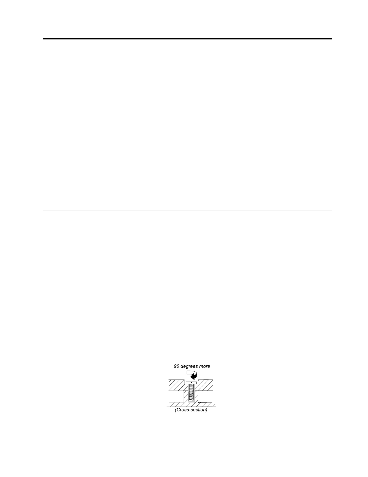
Screwnotices
Loosescrewscancauseareliabilityproblem.IntheThinkPadnotebookcomputer,thisproblemisaddressed
withspecialnylon-coatedscrewsthathavethefollowingcharacteristics:
•Theymaintaintightconnections.
•Theydonoteasilycomeloose,evenwithshockorvibration.
•Theyarehardertotighten.
Dothefollowingwhenyouservicethecomputer:
•Keepthescrewkitinyourtoolbag.Forthepartnumberofthescrewkit,goto
http://www.lenovo.com/serviceparts-lookup.
•Itisrecommendedtousenewscrews.
•Itisrecommendedtouseeachscrewonlyonce.
Tightenscrewsasfollows:
•Plastictoplastic
Turnanadditionalangleof90degreesafterthescrewheadtouchesthesurfaceoftheplasticpart.
•Logiccardtoplastic
Turnanadditionalangleof180degreesafterthescrewheadtouchesthesurfaceofthelogiccard.
©CopyrightLenovo2013
59
Page 66

Notes:
•Ensurethatyouusethecorrectscrew.Itisrecommendedtousenewscrewsforreplacements.Ifyou
haveatorquescrewdriver,tightenallscrewsrmlytothetorquespeciedinthescrewinformation
tableforeachstep.
•Ensuretorquescrewdriversarecalibratedcorrectlyfollowingcountryspecications.
Retainingserialnumbers
Thissectionincludesthefollowingdescriptions:
•“Restoringtheserialnumberofthesystemunit”onpage60
•“RetainingtheUUID”onpage61
Restoringtheserialnumberofthesystemunit
Whenthecomputerwasmanufactured,theElectricallyErasableProgrammableRead-OnlyMemory
(EEPROM)onthesystemboardwasloadedwiththeserialnumbersofthesystemandallmajorcomponents.
Thesenumbersneedtoremainthesamethroughoutthelifeofthecomputer.
Ifyoureplacethesystemboard,youmustrestoretheserialnumberofthesystemunittoitsoriginalvalue.
Theserialnumberofthesystemunitiswrittenonthelabelattachedtothebottomofthecomputer.
Ifyoucannotndtheserialnumberofthesystemunitonthebottomofthecomputer,trythefollowing
methodtogetthenumber:
Note:Beforeyouperformtheoperation,ensurethattheUEFI/LegacysettingwithintheStartupmenuin
theThinkPadSetupprogramissettoUEFIOnly.
1.ConnectaUSBmemorykeytothecomputer.
2.Gotohttp://www.lenovo.com/maintenanceutilitiesandfollowtheinstructionsonthescreentocreatea
MaintenanceKey.
Note:OnlyanauthorizedLenovoservicetechniciancanaccesstheaboveWebsite.
3.Restartthecomputer.
4.Whenthelogoisdisplayed,pressEsc.TheThinkPadCongInformationUpdateUtilityinterfaceis
displayed.
5.T ype1underEntertheactiondesired,thenpressEnter.TheThinkPadSerialNumberUpdateUtilityfor
AssetIDscreenisdisplayed.
6.T ype2underEntertheactiondesired,thenpressEnter.Theserialnumberofeachdeviceinyour
computerisdisplayed;theserialnumberofthesystemunitislistedasfollow:
20-Serialnumber
7.Recordtheserialnumberofthesystemunit.
Afteryoureplacethesystemboard,dothefollowingtorestoretheserialnumberofthesystemunit:
1.ConnecttheMaintenanceKeytothecomputer.
60HardwareMaintenanceManual
Page 67

2.Whenthelogoisdisplayed,pressEsc.TheThinkPadCongInformationUpdateUtilityinterfaceis
displayed.
3.T ype1underEntertheactiondesired,thenpressEnter.TheThinkPadSerialNumberUpdateUtilityfor
AssetIDscreenisdisplayed.
4.T ype1underEntertheactiondesired,thenpressEnter.Thenfollowtheinstructionsonthescreen
torestoretheserialnumberofthesystemunit.
RetainingtheUUID
Theuniversallyuniqueidentier(UUID)isa128-bitnumberuniquelyassignedtoyourcomputeratproduction
andstoredintheEEPROMofyoursystemboard.
ThealgorithmthatgeneratesthenumberisdesignedtoprovideuniqueIDsuntiltheyearA.D.3400.Notwo
computersintheworldhavethesamenumber.
Whenyoureplacethesystemboard,performthefollowingstepstocreateanewUUIDforthesystem
boardifthesystemboarddoesnothaveaUUID:
Note:Beforeyouperformtheoperation,ensurethattheUEFI/LegacysettingwithintheStartupmenuin
theThinkPadSetupprogramissettoUEFIOnly.
1.ConnectaUSBmemorykeytothecomputer.
2.Gotohttp://www.lenovo.com/maintenanceutilitiesandfollowtheinstructionsonthescreentocreatea
MaintenanceKey.
Note:OnlyanauthorizedLenovoservicetechniciancanaccesstheaboveWebsite.
3.Restartthecomputer.
4.Whenthelogoscreenisdisplayed,pressEsc.TheThinkPadCongInformationUpdateUtilityinterface
isdisplayed.
5.T ype2underEntertheactiondesired,thenpressEnter.TheAutoUUIDgenerationutilityinterfaceis
displayed.
6.T ypeyunderChangeUUID.OK?[Y/N],thenpressEnter.AnewUUIDiscreatedandwritten.Ifa
validUUIDalreadyexists,itisnotoverwritten.
Chapter8.FRUreplacementnotices61
Page 68

62HardwareMaintenanceManual
Page 69

Chapter9.RemovingorreplacingaFRU
ThischapterprovidesinstructionsonhowtoremoveorreplaceaFRU.
CRUstatementforcustomers:
Youcanresolvesomeproblemswithyourproductwithareplacementpartyoucaninstallyourself,called
a“CustomerReplaceableUnit”or“CRU.”SomeCRUsaredesignatedasself-serviceCRUsandothers
aredesignatedasoptional-serviceCRUs.Installationofself-serviceCRUsisyourresponsibility.For
optional-serviceCRUs,youcaneitherinstalltheCRUyourselforyoucanrequestthataServiceProvider
installtheCRUaccordingtothewarrantyserviceforyourproduct.IfyouintendoninstallingtheCRU,
LenovowillshiptheCRUtoyou.CRUinformationandreplacementinstructionsareshippedwithyour
productandareavailablefromLenovoatanytimeuponrequest.YoucanndalistofCRUsforyour
productinthisHardwareMaintenanceManual.Anelectronicversionofthismanualcanbefoundat
http://www.lenovo.com/support.ClickUserGuides&Manualsandthenfollowtheon-screeninstructions
tondthemanualforyourproduct.Y oumightberequiredtoreturnthedefectiveCRU.Whenreturn
isrequired:(1)returninstructions,aprepaidshippinglabel,andacontainerwillbeincludedwiththe
replacementCRU;and(2)youmightbechargedforthereplacementCRUifLenovodoesnotreceivethe
defectiveCRUwithinthirty(30)daysofyourreceiptofthereplacementCRU.SeeyourLenovoLimited
Warrantydocumentationforfulldetails.
Generalguidelines
WhenremovingorreplacingaFRU,besuretoobservethefollowinggeneralguidelines:
1.Donottrytoserviceanycomputerunlessyouhavebeentrainedandcertied.Anuntrainedpersonruns
theriskofdamagingparts.
2.BeforereplacinganyFRU,reviewChapter8“FRUreplacementnotices”onpage59.
3.BeginbyremovinganyFRUsthathavetoberemovedbeforereplacingthefailingFRU.Anysuch
FRUsarelistedatthebeginningofeachFRUreplacementprocedure.Removethemintheorderin
whichtheyarelisted.
4.FollowthecorrectsequenceinthestepsforremovingaFRU,asgiveninthedrawingsbythenumbers
insquarecallouts.
5.Whenturningascrew,turnitinthedirectionasgivenbythearrowinthedrawing.
6.WhenremovingaFRU,moveitinthedirectionasgivenbythearrowinthedrawing.
7.T oputthenewFRUinplace,reversetheremovalprocedureandfollowanynotesthatpertainto
replacement.Forinformationaboutconnectingandarranginginternalcables,seeChapter7“Locations”
onpage49
.
8.WhenreplacingaFRU,usethecorrectscrewsasshowninthereplacementprocedure.
DANGER
BeforeremovinganyFRU,turnoffthecomputer,unplugallpowercordsfromelectricaloutlets,
removethebatterypack,andthendisconnectanyinterconnectingcables.
Attention:
•AfterreplacingaFRU,donotturnonthecomputeruntilyouhavemadesurethatallscrews,springs,and
othersmallpartsareinplaceandnonearelooseinsidethecomputer.Verifythisbyshakingthecomputer
gentlyandlisteningforrattlingsounds.Metallicpartsormetalakescancauseelectricalshortcircuits.
•Thesystemboardissensitiveto,andcanbedamagedby,ESD.Beforetouchingit,establishpersonal
groundingbytouchingagroundpointwithonehandorbyusinganESDstrap.
©CopyrightLenovo2013
63
Page 70
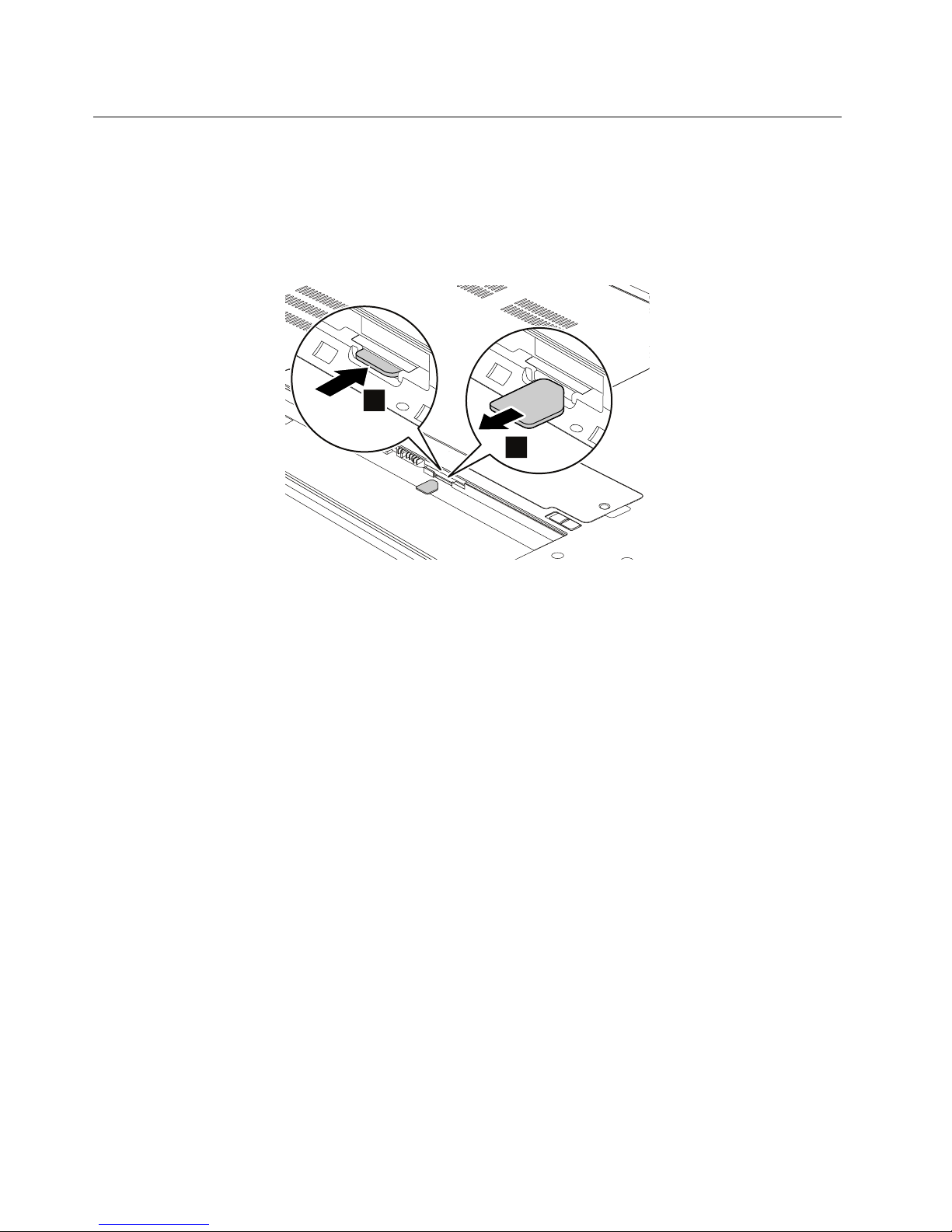
RemovingtheSIMcard
Thecomputeryouareservicingmighthaveasubscriberidentitymodule(SIM)cardthatthecustomerhas
installed.Insuchsituations,removetheSIMcardbeforeyoustarttheservicing.
ToremovetheSIMcard,youneedtoremovethebatterypackrst.See“1020Batterypack”onpage65.
Afteryounishtheservicing,ensurethatyouinsertthecardbackintotheslotrmly.
2
1
64HardwareMaintenanceManual
Page 71
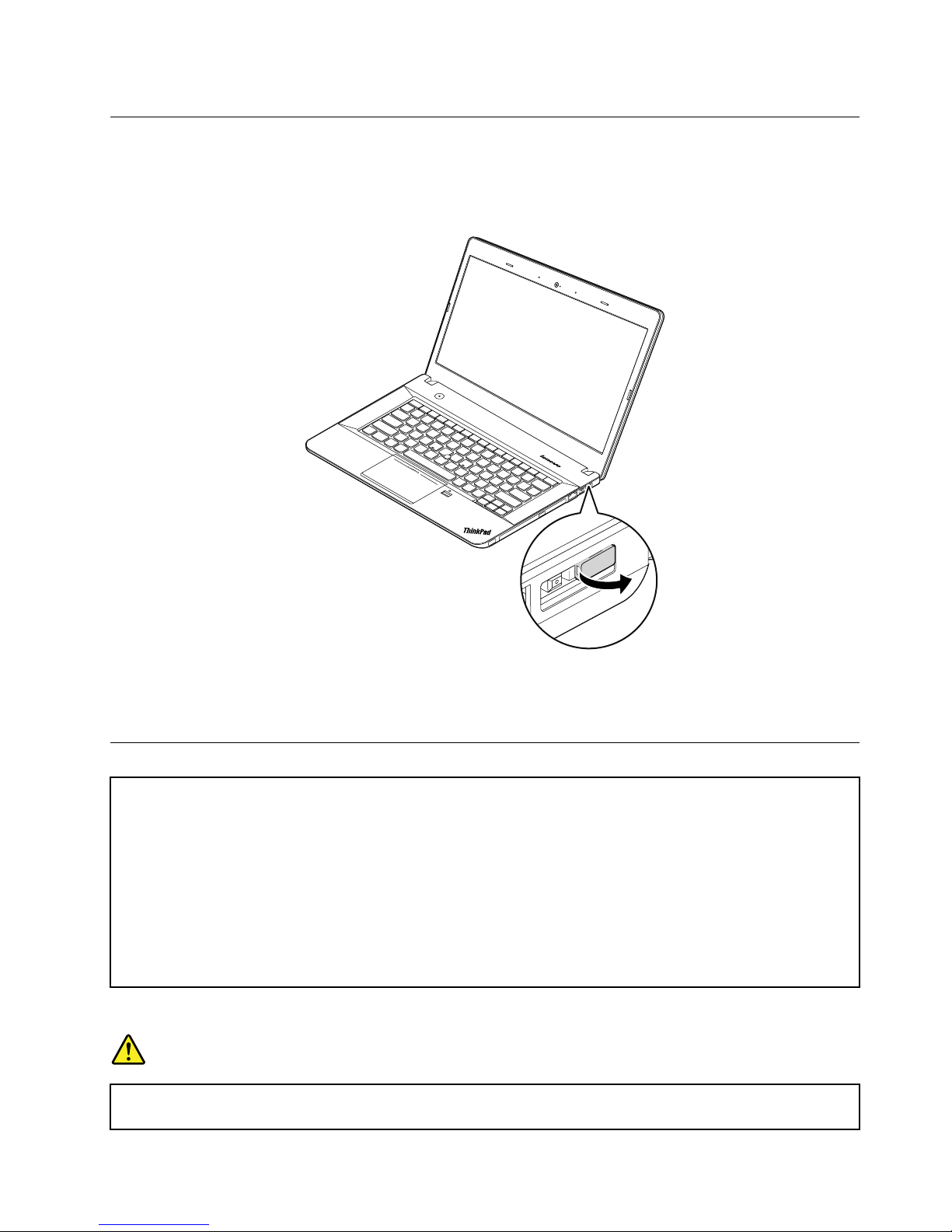
1010Lenovo-OneLink-connectorcover
RemovalstepsoftheLenovo-OneLink-connectorcover
Removetheconnectorcoverasshowninthefollowingillustration.
Note:
EnsurethatyoureattachtheconnectorcovertotheLenovo-OneLinkconnectorafternishingtheservicing.
1020Batterypack
Importantnoticeforreplacingabatterypack
Attention:Lenovohasnoresponsibilityfortheperformanceorsafetyofunauthorizedbatteries,andprovidesno
warrantiesforfailuresordamagearisingoutoftheiruse.
TheLenovoSolutionCenterprogramprovidesanautomaticbatterydiagnostictestthatdeterminesifthebattery
packisdefective.AbatterypackFRUshouldnotbereplacedunlessthisdiagnostictestshowsthatthebattery
packisdefective.Theonlyexceptiontothisisifthebatterypackisphysicallydamagedoracustomerisreporting
apossiblesafetyissue.
IfLenovoSolutionCenterisnotinstalledinthecomputer,thecustomershoulddownloadthisprogrambeforea
non-physicallydamagedbatterypackisreplaced.Notethataphysicallydamagedbatterypackisanon-warranty
replacementpart.
Removalstepsofthebatterypack
DANGER
Useonlytheauthorizedbatterypackspeciedforyourcomputer.Anyotherbatterypackcould
igniteorexplode.
Chapter9.RemovingorreplacingaFRU65
Page 72
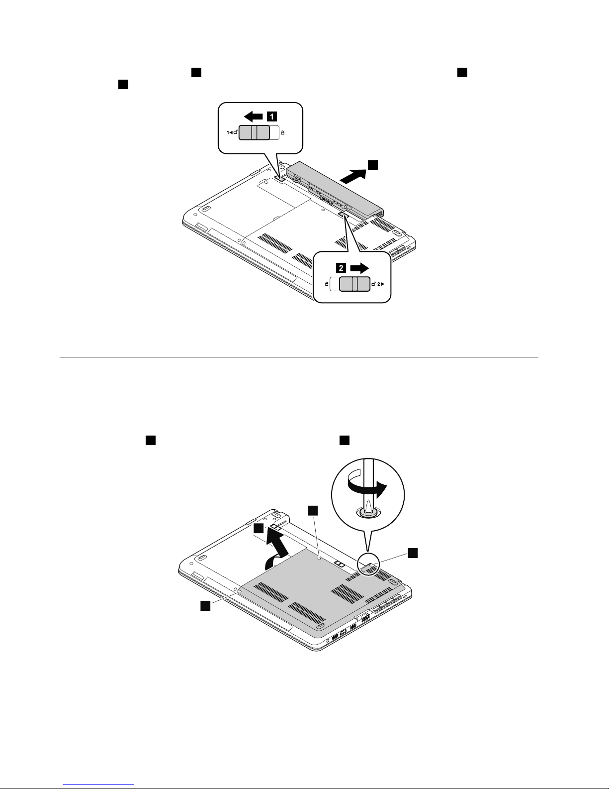
Unlockthebatterypacklatch1.Holdthebatterypacklockleverintheunlockedposition2andremovethe
batterypack3.
2
1
3
Wheninstalling:Installthebatterypackintotheslot.Ensurethatthebatterypacklatchisinthelocked
position.
1030Largebottomcover
Foraccess,removethisFRU:
•“1020Batterypack”onpage65
Removalstepsofthelargebottomcover
Loosenthescrews1andthenremovethelargebottomcover2.
1
1
1
2
66HardwareMaintenanceManual
Page 73
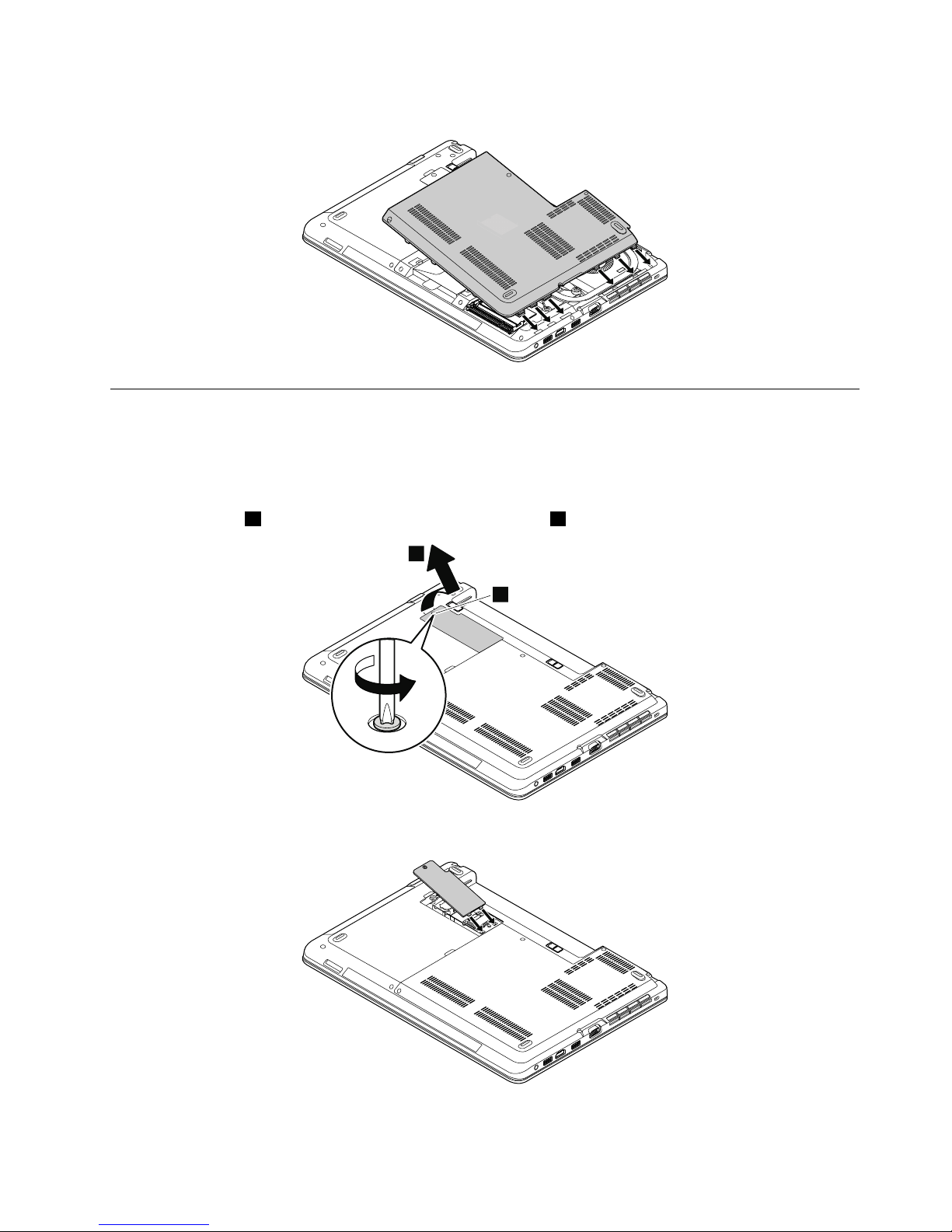
Wheninstalling:Attachthelargebottomcoverasshowninthefollowingillustration.
1040Smallbottomcover
Foraccess,removethisFRU:
•“1020Batterypack”onpage65
Removalstepsofthesmallbottomcover
Loosenthescrews1andthenremovethesmallbottomcover2.
2
1
Wheninstalling:Attachthesmallbottomcoverasshowninthefollowingillustration.
Chapter9.RemovingorreplacingaFRU67
Page 74
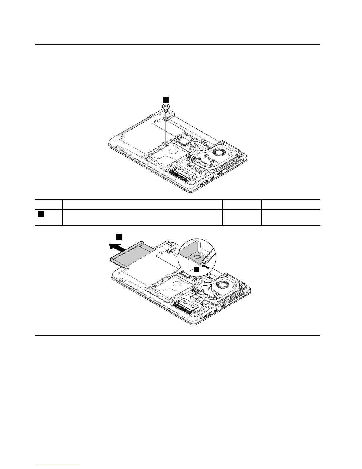
1050Opticaldriveoroptical-drivebaybezel
Foraccess,removetheseFRUsinorder:
•“1020Batterypack”onpage65
•“1030Largebottomcover”onpage66
Removalstepsoftheopticaldriveoroptical-drivebaybezel
1
StepScrew(quantity)Color
Torque
1
M2×3.5mm,wafer-head,nylon-coated(1)
Black0.181Nm
(1.85kgf-cm)
3
2
1060Memorymodule
Foraccess,removetheseFRUsinorder:
•“1020Batterypack”onpage65
•“1030Largebottomcover”onpage66
68HardwareMaintenanceManual
Page 75
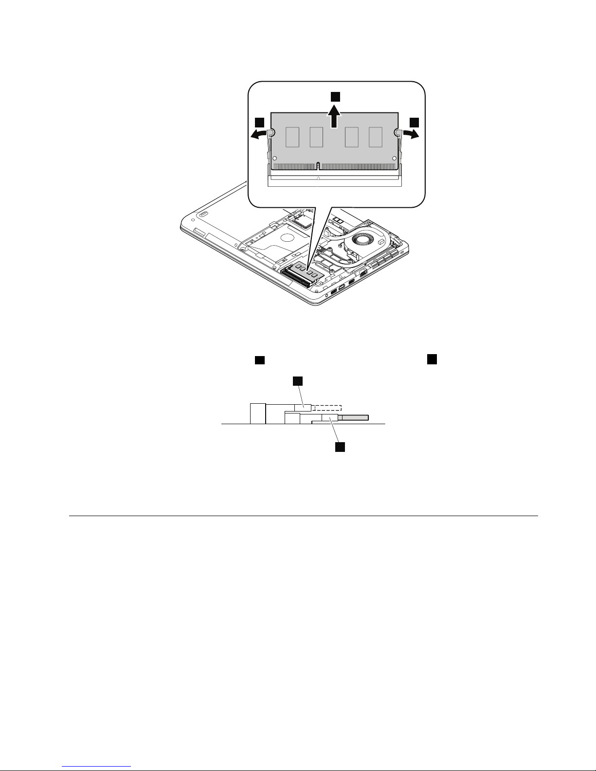
Removalstepsofthememorymodule
2
11
Wheninstalling:
Note:Ifonlyonememorymoduleistobeinstalledonthecomputeryouareservicing,thememorymodule
mustbeinstalledinthelowermemoryslota(SLOT-0),nottheuppermemoryslotb(SLOT-1).
b
a
Insertthenotchedendofthememorymoduleintotheslotatanangleofabout20degrees.Pressthe
memorymodulermly,andpivotitdownwardsuntilitsnapsintoplace.Ensurethatthememorymoduleis
rmlyinstalledintheslotanddoesnotmoveeasily.
1070Harddiskdrivewithbracketorsolid-statedrivewithbracket
Foraccess,removetheseFRUsinorder:
•“1020Batterypack”onpage65
•“1030Largebottomcover”onpage66
Attention:
•Donotdropthedriveorapplyanyphysicalshocktoit.Thedriveissensitivetophysicalshock.Improper
handlingcancausedamageandpermanentlossofdata.
•Beforeremovingthedrive,havetheusermakeabackupcopyofalltheinformationonitifpossible.
•Neverremovethedrivewhilethecomputerisoperatingorinsuspendmode.
Chapter9.RemovingorreplacingaFRU69
Page 76
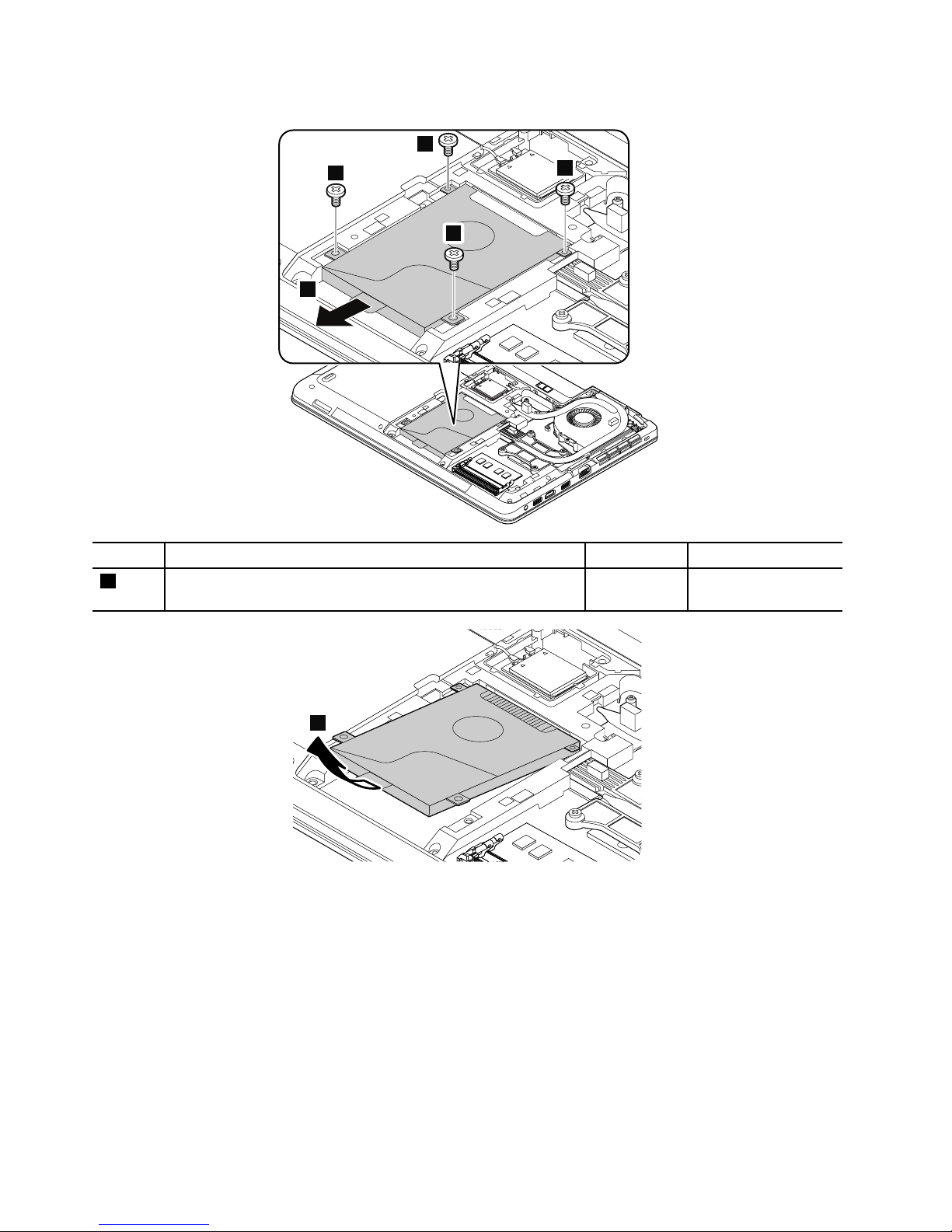
Removalstepsoftheharddiskdrivewithbracketorthesolid-statedrivewithbracket
1
1
1
1
2
StepScrew(quantity)Color
Torque
1
M2×3.5mm,wafer-head,nylon-coated(4)
Black0.181Nm
(1.85kgf-cm)
3
Wheninstalling:Ensurethattheharddiskdrivewithbracketorsolid-statedrivewithbracketisattached
rmly.
70HardwareMaintenanceManual
Page 77
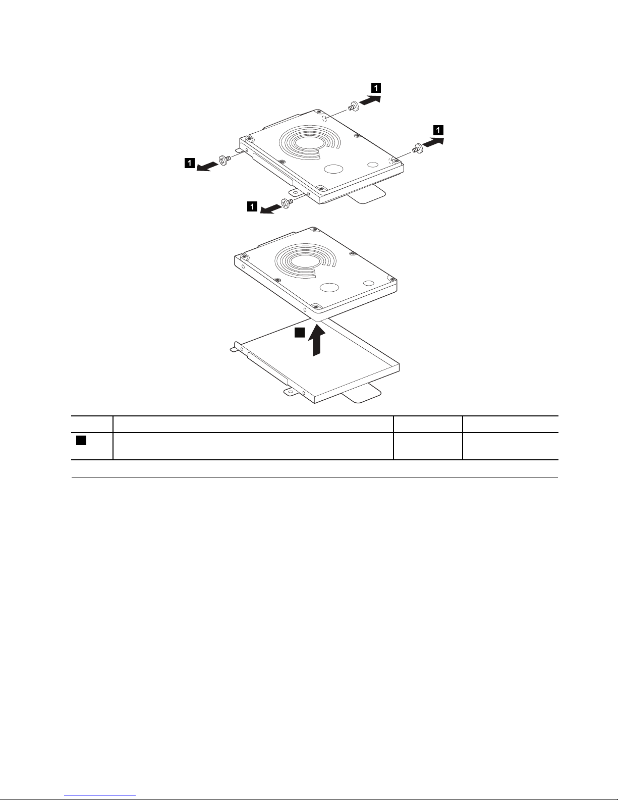
Removalstepsoftheharddiskdrivebracketorthesolid-statedrivebracket
1
1
1
1
2
StepScrew(quantity)Color
Torque
1
M3×3mm,wafer-head,nylon-coated(4)Silver
0.181Nm
(1.85kgf-cm)
1080Wireless-WANcardorM.2solid-statedrive
Foraccess,removetheseFRUsinorder:
•“1020Batterypack”onpage65
•“1030Largebottomcover”onpage66
Chapter9.RemovingorreplacingaFRU71
Page 78
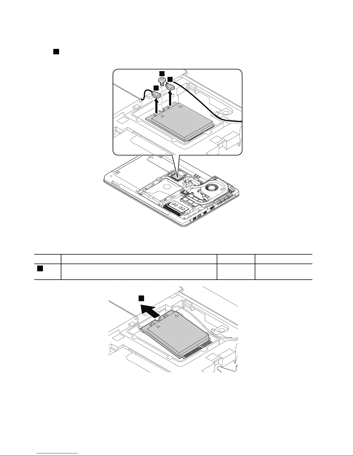
Removalstepsofthewireless-WANcard
Instep1,unplugtheconnectorsbyusingtheantennaRFconnectorremovaltoolorpicktheconnectors
withyourngersandgentlyunplugthemasshown.
2
1
1
Wheninstalling:PlugtheredcableintotheconnectormarkedMAIN,andthebluecableintotheconnector
markedAUXonthecard.
StepScrew(quantity)Color
Torque
2
M2×3.5mm,wafer-head,nylon-coated(1)
Black0.181Nm
(1.85kgf-cm)
3
RemovalstepsoftheM.2solid-statedrive
Attention:
•Donotdropthedriveorapplyanyphysicalshocktoit.Thedriveissensitivetophysicalshock.Improper
handlingcancausedamageandpermanentlossofdata.
72HardwareMaintenanceManual
Page 79
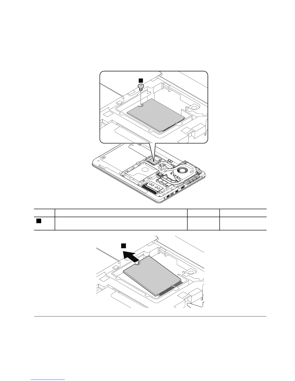
•Beforeremovingthedrive,havetheusermakeabackupcopyofalltheinformationonitifpossible.
•Neverremovethedrivewhilethecomputerisoperatingorisinsuspendmode.
•EnsurethatyoupartitiontheM.2solid-statedriveafterinstallingitonthecomputeryouareservicing.
Otherwise,theM.2solid-statedrivewillnotfunctioncorrectly.Forinstructionsononhowtopartitionan
M.2solid-statedrive,gotohttp://www.lenovo.com/support/msata-fru.
1
StepScrew(quantity)Color
Torque
1
M2×3.5mm,wafer-head,nylon-coated(1)
Black0.181Nm
(1.85kgf-cm)
2
1090Wireless-LAN/Bluetoothcard
Foraccess,removetheseFRUsinorder:
•“1020Batterypack”onpage65
•“1040Smallbottomcover”onpage67
Chapter9.RemovingorreplacingaFRU73
Page 80
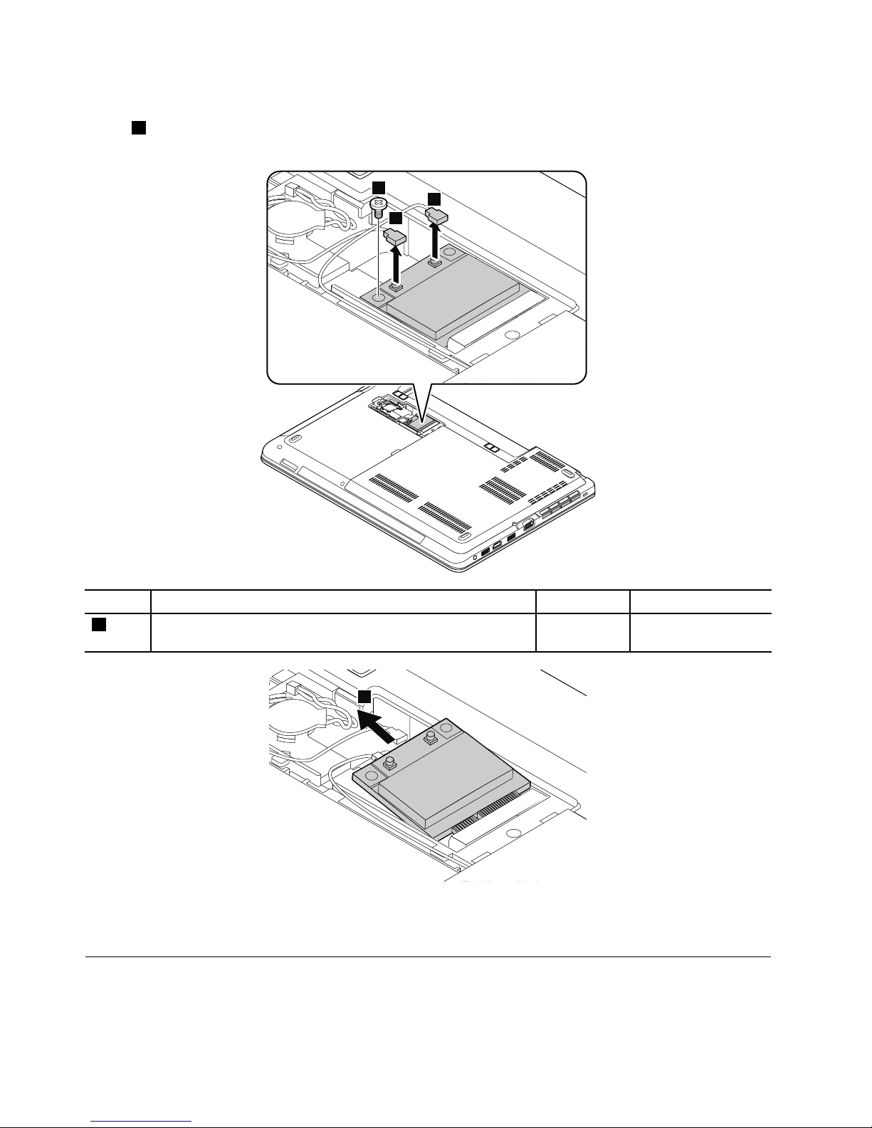
Removalstepsofthewireless-LAN/Bluetoothcard
Instep1,unplugtheconnectorsbyusingtheantennaRFconnectorremovaltoolorpicktheconnectors
withyourngersandgentlyunplugthemasshown.
2
1
1
StepScrew(quantity)Color
Torque
2
M2×3.5mm,wafer-head,nylon-coated(1)
Black0.181Nm
(1.85kgf-cm)
3
Wheninstalling:PlugthegraycableintotheconnectormarkedMAINorM,andtheblackcableintothe
connectormarkedAUXorAonthecard.
1100Coin-cellbattery
Foraccess,removetheseFRUsinorder:
•“1020Batterypack”onpage65
74HardwareMaintenanceManual
Page 81
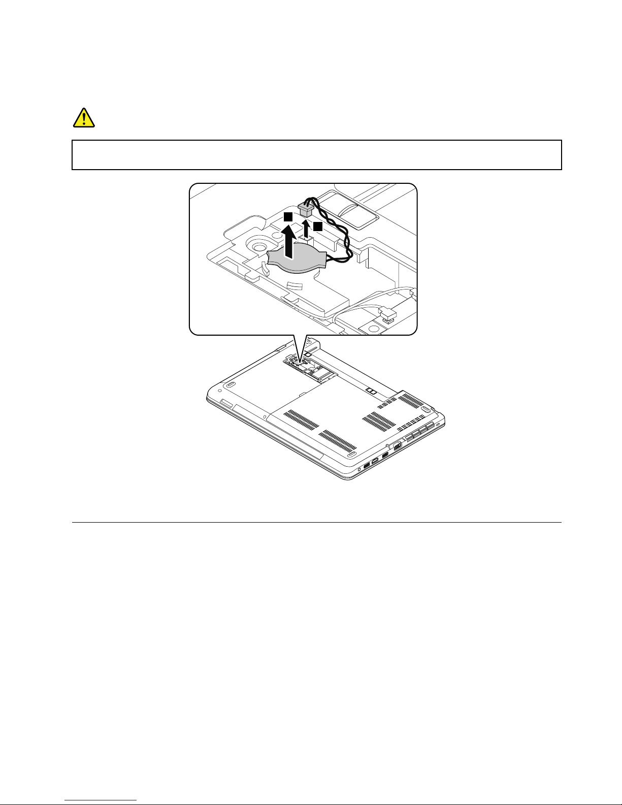
•“1040Smallbottomcover”onpage67
Removalstepsofthecoin-cellbattery
DANGER
Useonlytheauthorizedcoin-cellbatteryspeciedforyourcomputer .Anyothercoin-cellbattery
couldigniteorexplode.
2
1
Wheninstalling:Ensurethattheconnectorisattachedrmly.
1110Thermalmodule
Foraccess,removetheseFRUsinorder:
•“1020Batterypack”onpage65
•“1030Largebottomcover”onpage66
Chapter9.RemovingorreplacingaFRU75
Page 82
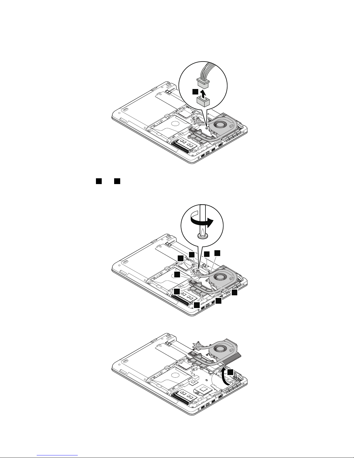
Removalstepsofthethermalmodule
1.Detachtheconnector.
1
Wheninstalling:Ensurethattheconnectorisattachedrmlytothesystemboard.
2.Loosenthescrews2and3inascendingalphabeticalorderasillustrated.
Note:Differentmodelsmighthavedifferentnumbersofscrews.
2g
2f
3a
2c
2b
2d
2a
3b
2e
3.Removethethermalmodule.
4
76HardwareMaintenanceManual
Page 83
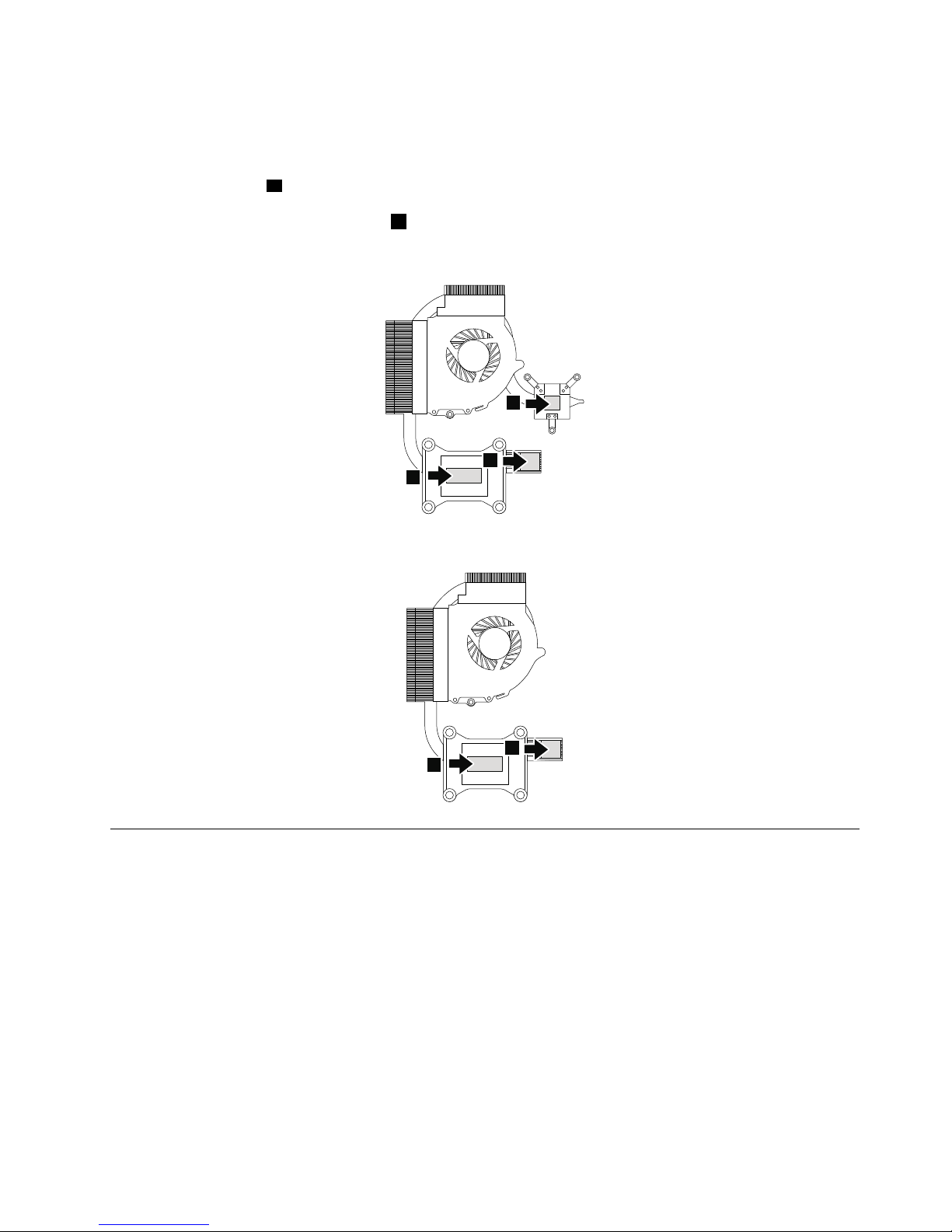
Wheninstalling:
•Donotpressthetopofthethermalmodulecoverandthethermalmodulehub.
•Beforeyouattachthethermalmoduletothecomputer,applythermalgrease,atanamountof0.2grams,
onthepartmarkedaasshowninthefollowingillustrations.Eithertoomuchortoolessapplicationof
greasecancauseathermalproblemduetoimperfectcontactwithacomponent.Y ouneedtopeelthe
thinlmofffromtherubbersmarked
b.
Formodelswithdiscretethermalpipes
a
a
b
Formodelswithintegratedthermalpipes
a
b
1120Keyboard
Foraccess,removetheseFRUsinorder:
•“1020Batterypack”onpage65
Chapter9.RemovingorreplacingaFRU77
Page 84
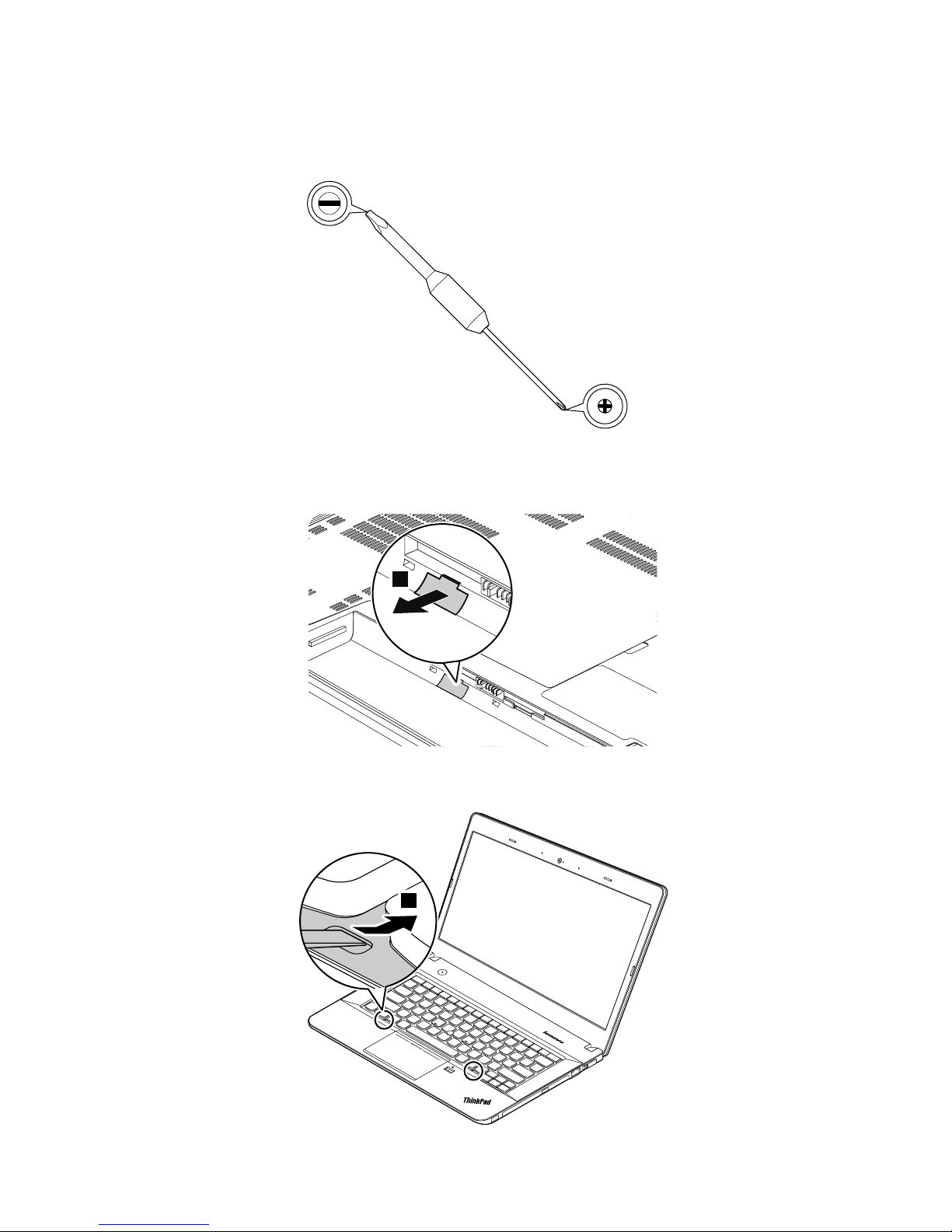
Keyboardmulti-tool
Whenyouremovethekeyboard,usethekeyboardmulti-tool.Thefollowingillustrationshowsakeyboard
multi-tool.
Removalstepsofthekeyboard
1.Unlockthekeyboardframe.
1
2.T orevealthescrewheadsbeneaththekeyboardframe,slidethekeyboardframeforwardby2.5mm
(0.1inch)withthekeyboardmulti-tool.
2
78HardwareMaintenanceManual
Page 85
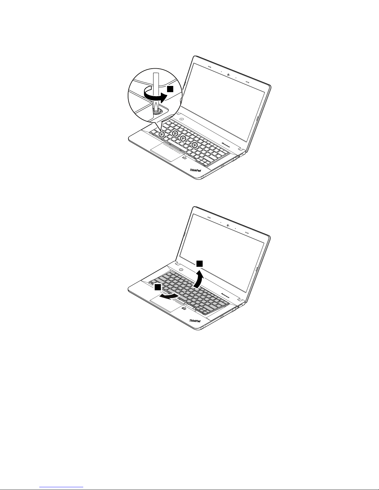
3.Loosenthescrewsthatsecurethekeyboardwiththekeyboardmulti-tool.
3
4.Pivotthekeyboardslightlyupwarduntilyoucanseetheconnectorsonthebottomsideofthekeyboard.
Thenturnoverthekeyboard.
4
5
Chapter9.RemovingorreplacingaFRU79
Page 86
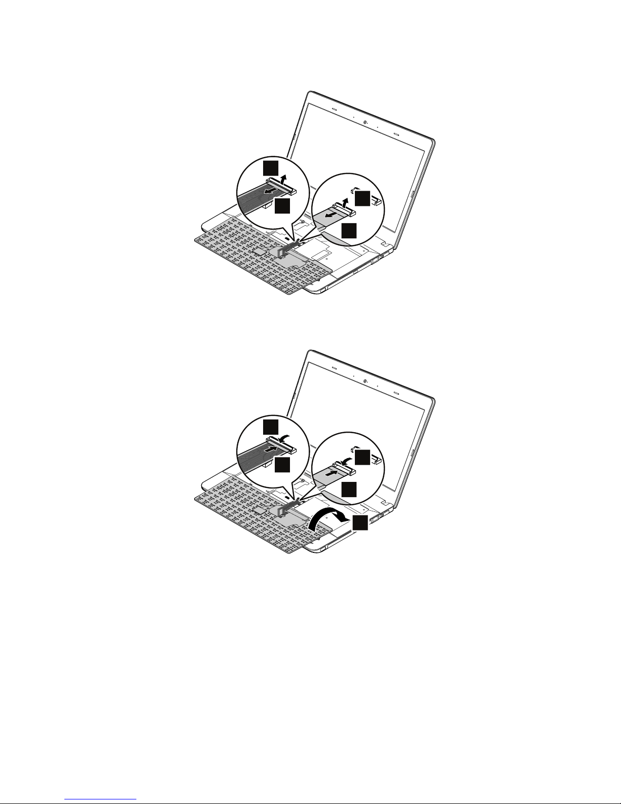
5.Gentlyputthekeyboardonthepalmrestanddetachtheconnectors.Thenremovethekeyboard.
6
7
8
9
Installationstepsofthekeyboard
1.Attachtheconnectorsandthenturnoverthekeyboard.
4
3
2
1
5
80HardwareMaintenanceManual
Page 87
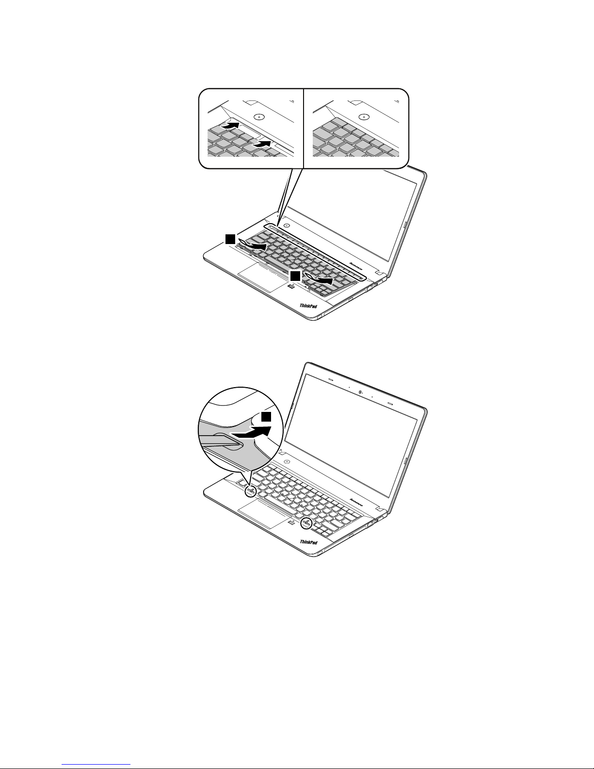
2.Insertthekeyboardintothespaceundertheframeofthekeyboardbezel.
6
6
3.Revealthescrewheadsbyslidingthekeyboardframeforwardwiththekeyboardmulti-tool.Ensure
thatthescrewheadsareexposedcompletely.
7
Chapter9.RemovingorreplacingaFRU81
Page 88
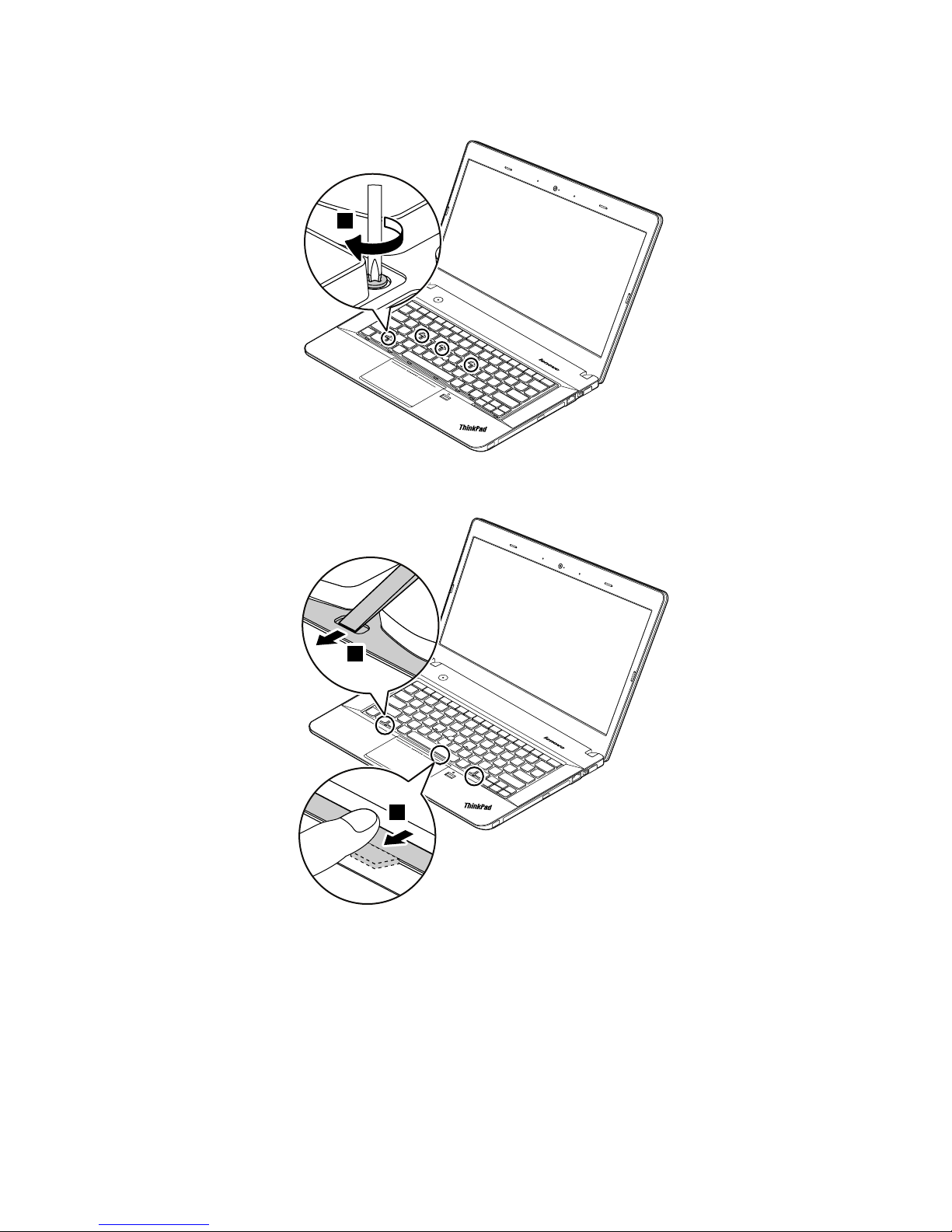
4.Tightenthescrewswiththekeyboardmulti-tooltosecurethekeyboardinplace.
8
5.Slidethekeyboardframebackwardby2.5mm(0.1inch)withthekeyboardmulti-tool.Hidethelatches
ofthekeyboardframeunderthekeyboardbezelbypushingthelatcheswithyourngerasshown.
9
9
82HardwareMaintenanceManual
Page 89
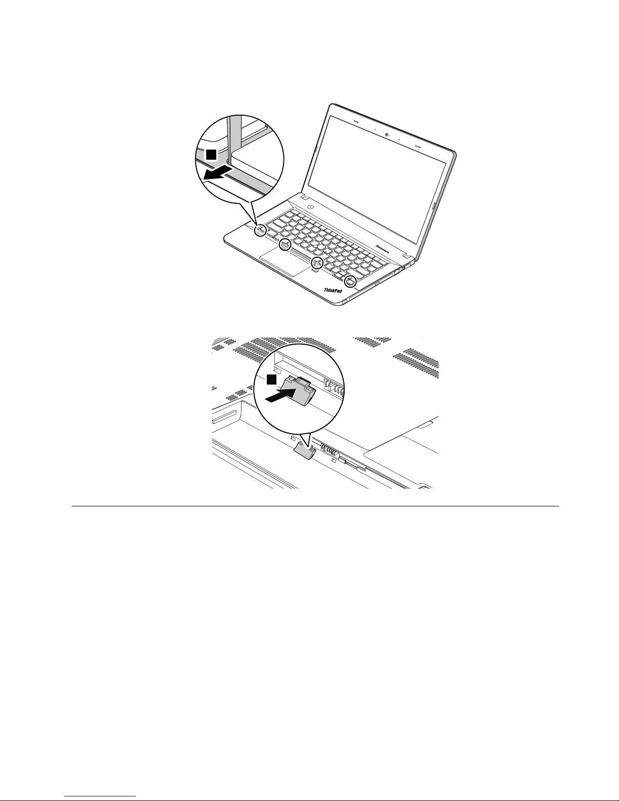
6.Adjustthekeyboardframeinplacewiththekeyboardmulti-toolandensurethatallthelatchesare
securedunderthekeyboardbezel.
10
7.T urnthecomputeroverandlockthekeyboardframe.
11
1130Keyboardbezelassembly
Foraccess,removetheseFRUsinorder:
•“1020Batterypack”onpage65
•“1030Largebottomcover”onpage66
•“1050Opticaldriveoroptical-drivebaybezel”onpage68
•“1070Harddiskdrivewithbracketorsolid-statedrivewithbracket”onpage69
•“1120Keyboard”onpage77
Chapter9.RemovingorreplacingaFRU83
Page 90
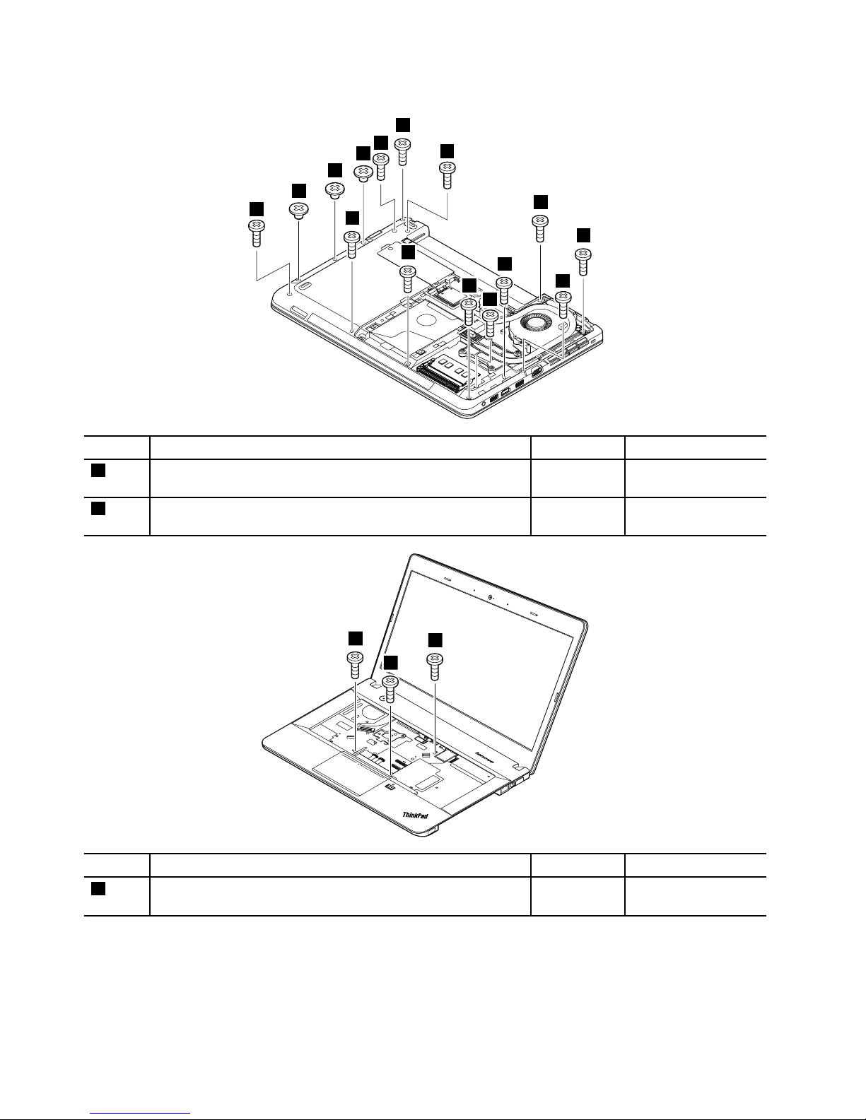
Removalstepsofthekeyboardbezelassembly
2
2
2
1
1
1
1
1
1
1
1
1
1
1
1
StepScrew(quantity)Color
Torque
1
M2×7mm,wafer-head,nylon-coated(12)
Black0.181Nm
(1.85kgf-cm)
2
M2×2.5mm,wafer-head,nylon-coated(3)
Black0.181Nm
(1.85kgf-cm)
3
3
3
StepScrew(quantity)Color
Torque
3
M2×7mm,wafer-head,nylon-coated(3)
Black0.181Nm
(1.85kgf-cm)
84HardwareMaintenanceManual
Page 91
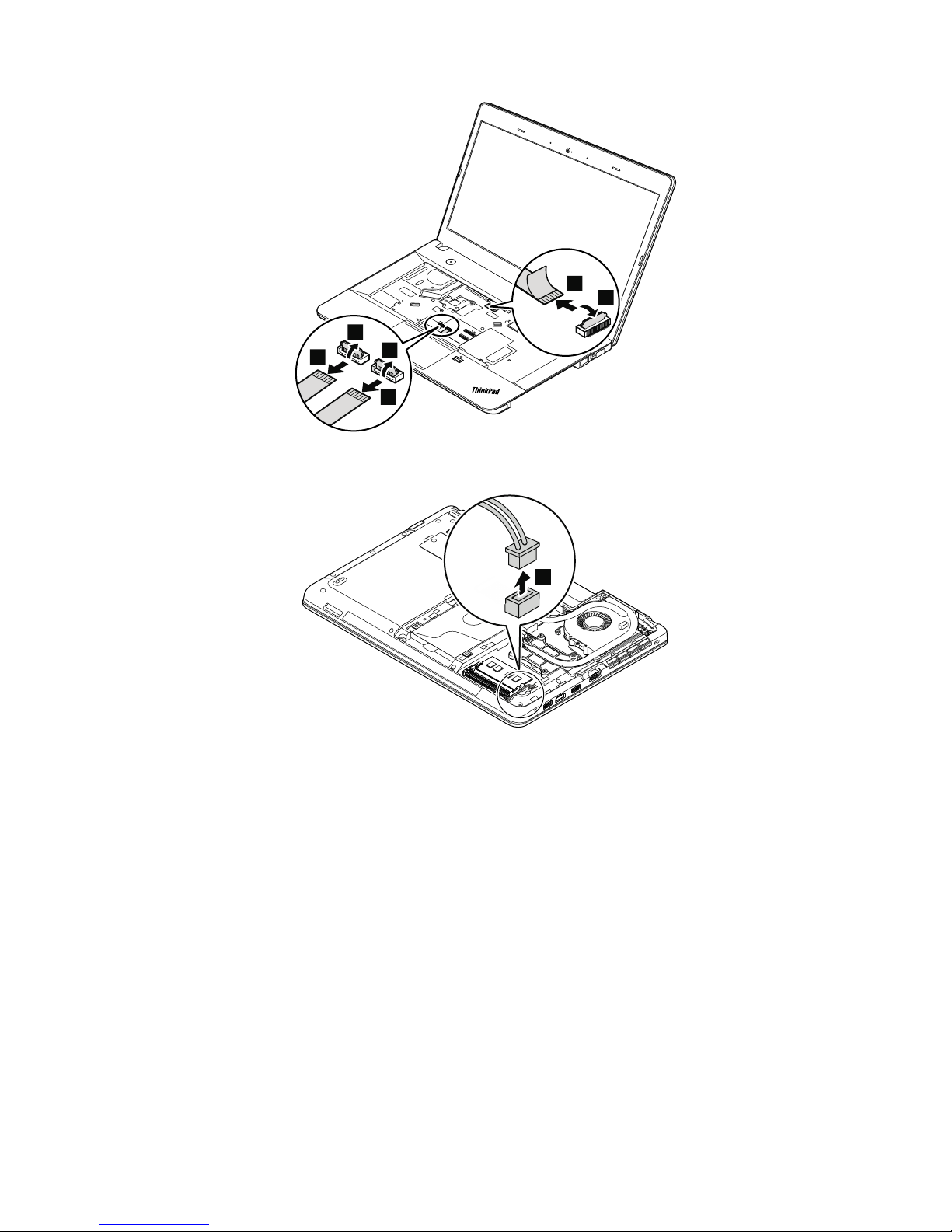
5
4
8
9
6
7
Wheninstalling:Ensurethattheconnectorsareattachedrmlytothesystemboard.
10
Wheninstalling:Ensurethattheconnectorsareattachedrmlytothesystemboard.
Chapter9.RemovingorreplacingaFRU85
Page 92
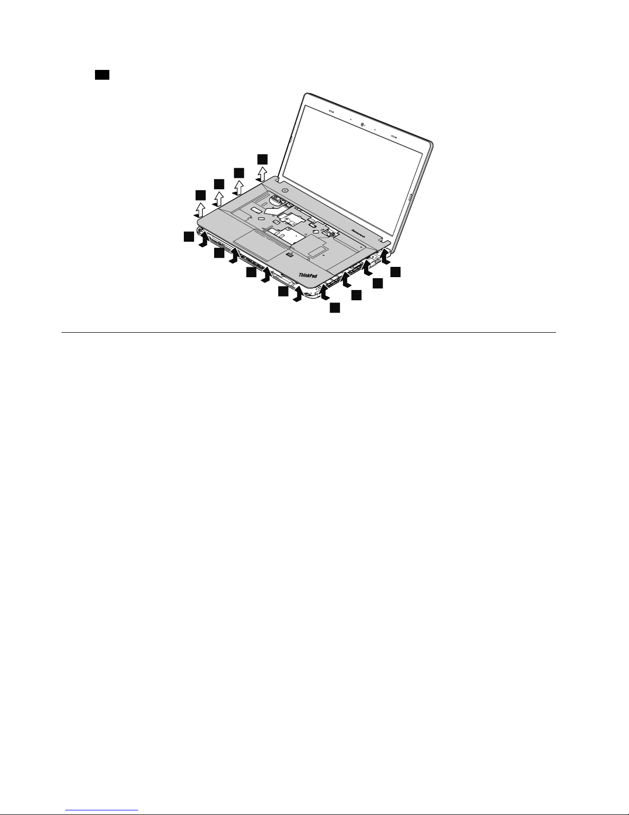
Instep11,releasethekeyboardbezelassemblyfromtheframeusingaplasticprytool.
11
11
11
11
11
11
11
11
11
11
11
11
1140Microprocessor
Foraccess,removetheseFRUsinorder:
•“1020Batterypack”onpage65
•“1030Largebottomcover”onpage66
•“1110Thermalmodule”onpage75
Attention:Themicroprocessorisextremelysensitive.Whenyouservicethemicroprocessor,avoidany
kindofroughhandling.
86HardwareMaintenanceManual
Page 93
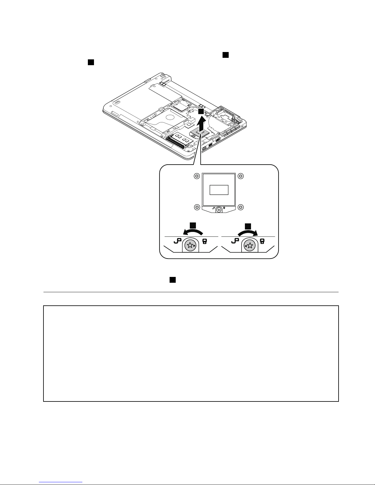
Removalstepsofthemicroprocessor
Rotatetheheadofthescrewinthedirectionshownbythearrow1toreleasethelock;thenremovethe
microprocessor2.
1
3
2
Wheninstalling:Placethemicroprocessorabovethemicroprocessorsocket,andthenrotatetheheadof
thescrewinthedirectionshownbythearrow3tosecurethemicroprocessor.
1150Systemboard
Importantnoticesforhandlingthesystemboard:
Whenhandlingthesystemboard,readthefollowing:
•Thesystemboardhasanaccelerometer,whichcanbebrokenwhenseveralthousandsofG-forcesareapplied.
Note:Droppingasystemboardfromaheightofaslittleas6inchessothatitfallsatonahardbenchcansubject
theaccelerometertoasmuchas6000G'sofshock.
•Becarefulnottodropthesystemboardonabenchtopthathasahardsurface,suchasmetal,wood,orcomposite.
•Avoidroughhandlingofanykind.
•Ateverypointintheprocess,besurenottodroporstackthesystemboard.
•Ifyouputasystemboarddown,besuretoputitonlyonapaddedsurfacesuchasanESDmatoracorrugated
conductivesurface.
Foraccess,removetheseFRUsinorder:
•“1020Batterypack”onpage65
•“1030Largebottomcover”onpage66
•“1040Smallbottomcover”onpage67
Chapter9.RemovingorreplacingaFRU87
Page 94
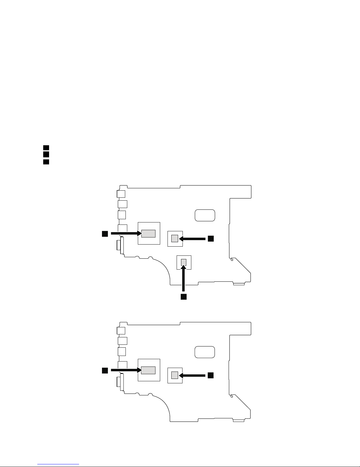
•“1050Opticaldriveoroptical-drivebaybezel”onpage68
•“1060Memorymodule”onpage68
•“1070Harddiskdrivewithbracketorsolid-statedrivewithbracket”onpage69
•“1080Wireless-WANcardorM.2solid-statedrive”onpage71
•“1090Wireless-LAN/Bluetoothcard”onpage73
•“1100Coin-cellbattery”onpage74
•“1110Thermalmodule”onpage75
•“1120Keyboard”onpage77
•“1130Keyboardbezelassembly”onpage83
•“1140Microprocessor”onpage86
Removalstepsofthesystemboard
Attention:Thefollowingcomponentssolderedonthetopsideofthesystemboardareextremelysensitive.
Whenyouservicethesystemboard,avoidanykindofroughhandling.
aMicroprocessor
bPlatformControllerHub(PCH)
cGraphicsprocessingunit(GPU)
Formodelswithdiscretethermalpipes
a
c
b
Formodelswithintegratedthermalpipes
a
b
88HardwareMaintenanceManual
Page 95
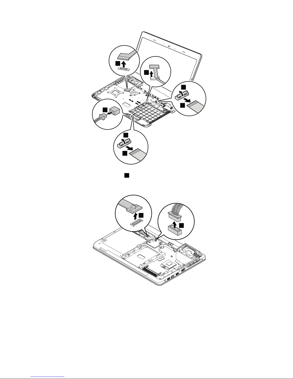
4
3
2
1
5
6
7
Note:TheLCD-control-cardcableinstep7isonlyavailableonmodelswithtouchscreen.
Wheninstalling:Ensurethattheconnectorsareattachedrmlytothesystemboard.
7
8
Wheninstalling:Ensurethattheconnectorsareattachedrmlytothesystemboard.
Chapter9.RemovingorreplacingaFRU89
Page 96
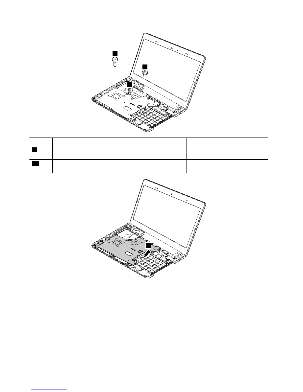
5
6
9
10
10
StepScrew(quantity)Color
Torque
9
M2×7mm,wafer-head,nylon-coated(1)
Black0.181Nm
(1.85kgf-cm)
10
M2×3.5mm,wafer-head,nylon-coated(2)
Black0.181Nm
(1.85kgf-cm)
5
6
11
1160Media-card-reader/USBcard
Foraccess,removetheseFRUsinorder:
•“1020Batterypack”onpage65
•“1030Largebottomcover”onpage66
•“1050Opticaldriveoroptical-drivebaybezel”onpage68
•“1070Harddiskdrivewithbracketorsolid-statedrivewithbracket”onpage69
•“1120Keyboard”onpage77
•“1130Keyboardbezelassembly”onpage83
90HardwareMaintenanceManual
Page 97
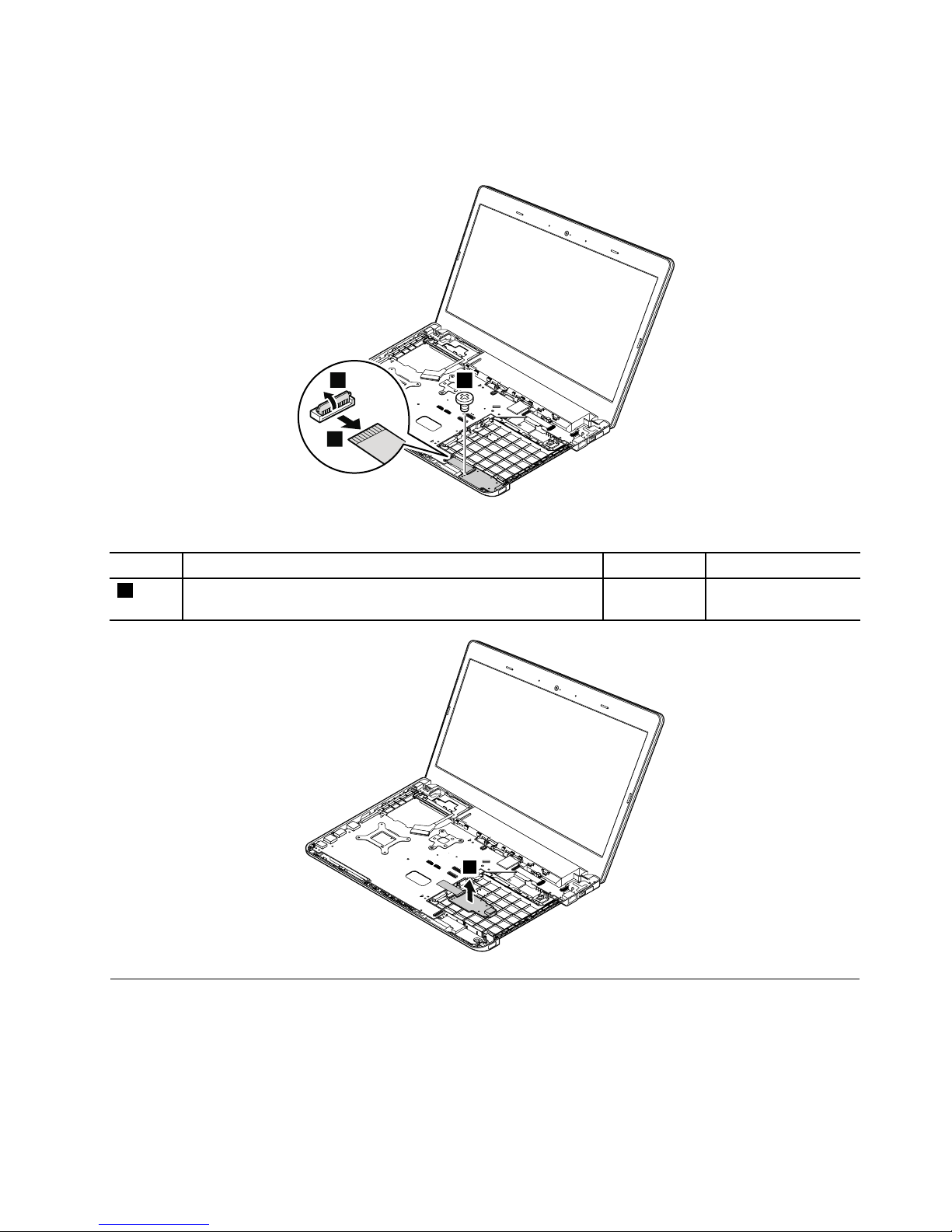
RemovalstepsoftheMedia-card-reader/USBcard
Note:Thesystemboardofthecomputerthatyouareservicingmightbedifferentfromtheoneinthe
followingillustrations.
6
3
2
1
Wheninstalling:Ensurethattheconnectorisattachedrmlytothesystemboard.
StepScrew(quantity)Color
Torque
3
M2×3.5mm,wafer-head,nylon-coated(1)
Black0.181Nm
(1.85kgf-cm)
4
6
1170dc-in/Ethenetcardbracketanddc-in/Ethenetcard
Foraccess,removetheseFRUsinorder:
•“1010Lenovo-OneLink-connectorcover”onpage65
•“1020Batterypack”onpage65
•“1030Largebottomcover”onpage66
•“1050Opticaldriveoroptical-drivebaybezel”onpage68
•“1070Harddiskdrivewithbracketorsolid-statedrivewithbracket”onpage69
Chapter9.RemovingorreplacingaFRU91
Page 98
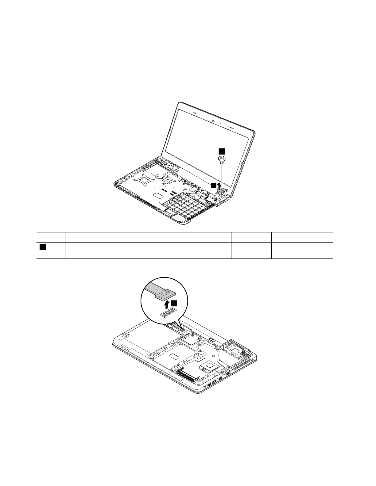
•“1100Coin-cellbattery”onpage74
•“1120Keyboard”onpage77
•“1130Keyboardbezelassembly”onpage83
Removalstepsofthedc-in/Ethenetcardbracket
Note:Thesystemboardofthecomputerthatyouareservicingmightbedifferentfromtheoneinthe
followingillustration.
5
1
2
StepScrew(quantity)Color
Torque
1
M2×3.5mm,wafer-head,nylon-coated(1)
Black0.181Nm
(1.85kgf-cm)
Removalstepsofthedc-in/Ethenetcard
1
92HardwareMaintenanceManual
Page 99
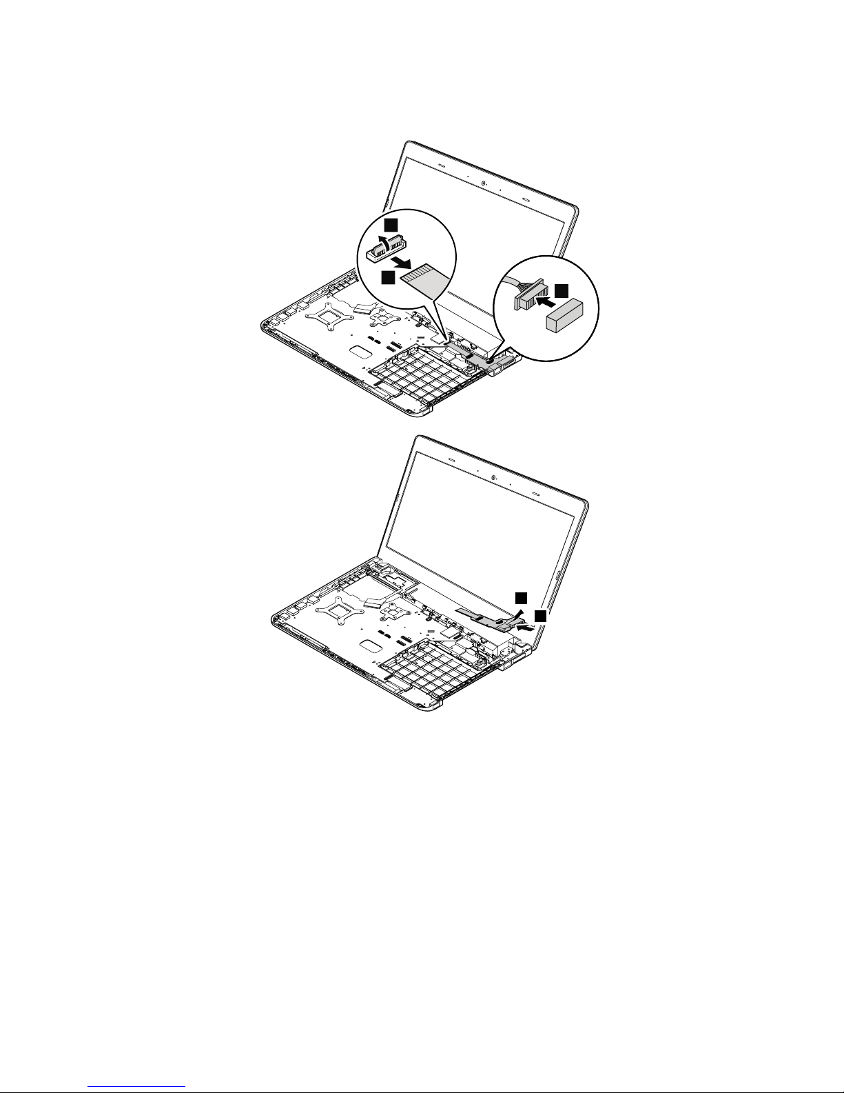
Note:Thesystemboardofthecomputerthatyouareservicingmightbedifferentfromtheoneinthe
followingillustrations.
5
6
3
2
4
5
6
6
5
Chapter9.RemovingorreplacingaFRU93
Page 100
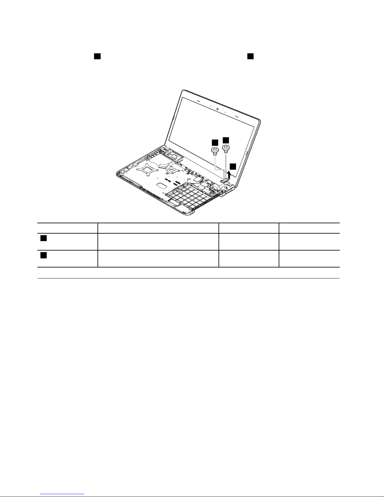
Removalstepsofthedc-in/Ethenetcardsupportbracket
Removethescrews1andremovethedc-in/Ethenetcardsupportbracket2.
Note:Thesystemboardofthecomputerthatyouareservicingmightbedifferentfromtheoneinthe
followingillustration.
1
1
2
StepScrew(quantity)Color
Torque
1
M2.5×5mm,wafer-head,nylon-coated(1)
Black0.294Nm
(3kgf-cm)
1
M2×3mm,wafer-head,nylon-coated(1)Silver
0.181Nm
(1.85kgf-cm)
1180Speakerassembly
Foraccess,removetheseFRUsinorder:
•“1020Batterypack”onpage65
•“1030Largebottomcover”onpage66
•“1040Smallbottomcover”onpage67
•“1050Opticaldriveoroptical-drivebaybezel”onpage68
•“1070Harddiskdrivewithbracketorsolid-statedrivewithbracket”onpage69
•“1080Wireless-WANcardorM.2solid-statedrive”onpage71
•“1090Wireless-LAN/Bluetoothcard”onpage73
•“1100Coin-cellbattery”onpage74
•“1110Thermalmodule”onpage75
•“1120Keyboard”onpage77
•“1130Keyboardbezelassembly”onpage83
•“1150Systemboard”onpage87
•“1160Media-card-reader/USBcard”onpage90
94HardwareMaintenanceManual
 Loading...