

Page 1
Page 2

Copyright Notice
Copyright © 2012. All rights reserved. Printed in the U.S.A.
Thinklogical, LLC®
100 Washington Street
Milford, Connecticut 06460 U.S.A.
Telephone: 1-203-647-8700
Fax: 1-203-783-9949
All trademarks and service marks are property of their respective owners.
Subject: X4 Configurator Product Manual
Revision: October, 2012
X4 Configurator Manual 2 October, 2012
Page 3

Table of Contents
PREFACE................................................................................................................................... 4
Conventions Used in this Manual ............................................................................................ 4
X4 CONFIGURATOR SOFTWARE PACKAGE.......................................................................... 5
Overview .................................................................................................................................... 5
Linux Installation ................................................................................................................. 5
Windows Installation........................................................................................................... 5
Firewall Considerations ...................................................................................................... 8
X4 Configurator Login .............................................................................................................. 8
Introduction ......................................................................................................................... 9
ADMIN: Routers ................................................................................................................. 10
ADMIN: Stations ................................................................................................................ 13
Adding new ports ........................................................................................................... 17
Import/Export Station Configurations ........................................................................... 18
ADMIN: Tie Lines ............................................................................................................... 22
Using and Monitoring Tie Lines .................................................................................... 24
ADMIN: Snapshots ............................................................................................................ 29
ADMIN: Log ....................................................................................................................... 31
ADMIN: Help ...................................................................................................................... 32
CONNECT Page....................................................................................................................... 33
Stations Categories .......................................................................................................... 36
MACROS Page ........................................................................................................................ 40
Creating/Editing/Deleting Macros .................................................................................... 44
STUDIO Page ........................................................................................................................... 48
COMBI Page ............................................................................................................................ 55
Multiple Browser Tabs ...................................................................................................... 58
GROUPS Page ......................................................................................................................... 59
Appendixes ............................................................................................................................. 67
File Locations .................................................................................................................... 67
Other DocumentationX4 Configurator Login .................................................................. 67
HOW TO CONTACT US ........................................................................................................... 68
Customer Support .................................................................................................................. 68
Website ................................................................................................................................ 68
Email ................................................................................................................................... 68
Telephone ........................................................................................................................... 68
Fax ...................................................................................................................................... 69
Product Support ...................................................................................................................... 69
Limited Warranty Information ........................................................................................... 69
Our Address ....................................................................................................................... 70
X4 Configurator Manual 3 October, 2012
Page 4
PREFACE
Conventions Used in this Manual
As you read this manual you will notice certain conventions that bring your attention to important
information. These are Notes and Warnings. Examples are shown below.
Note: Important Notes appear in blue text preceded by a yellow exclamation point symbol,
like this.
A note is meant to call the reader’s attention to helpful information at a point in the text that is relevant to
the subject being discussed.
Warning! All Warnings appear in red text, followed by blue text, and preceded by a red
stop sign, like this.
A warning is meant to call the reader’s attention to critical information at a point in the text that is relevant
to the subject being discussed.
X4 Configurator Manual 4 October, 2012
Page 5
X4 Configurator Software Package
Overview
X4 is a web-based control system for Thinklogical’s® family of VX, MX, and HDX routers. It runs on a
separate Windows or Linux computer and allows for easy configuration, management and control of any
number of routers.
The installation files, rpm for Linux and exe for Windows, will be on the included CD and are also
available from the Thinklogical FTP site: http://ftp.thinklogical.com/ftp/VxRouter/X44/
Please choose the latest version for your chosen platform (Linux or Windows).
Linux Installation
The Linux installation using yum or rpm is automatic and allows a few installation options:
First time installation: rpm –I filename.rpm
Upgrade existing installation: rpm –U filename.rpm
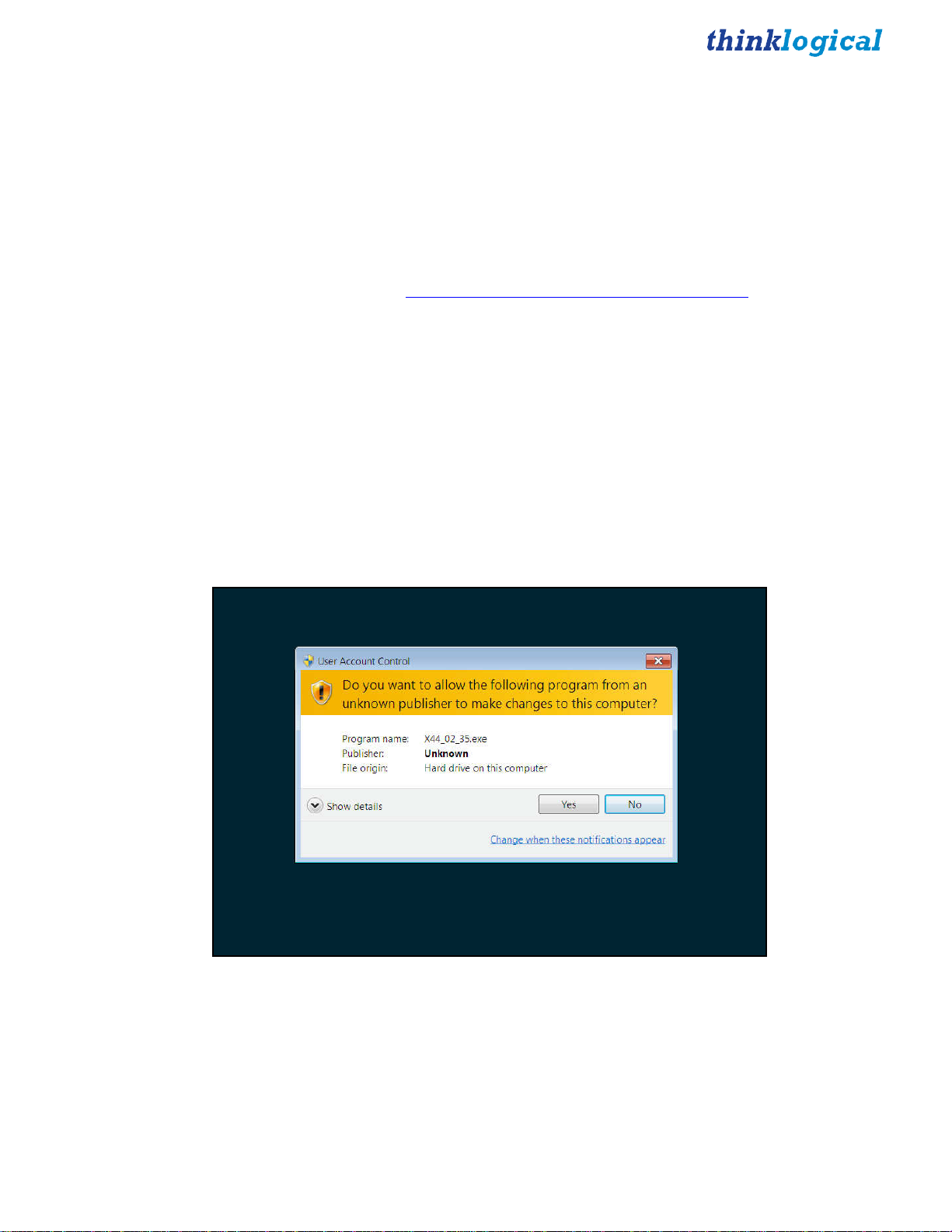
Windows Installation
The Windows installation program will have a name similar to X44_02_41.exe
When executed, Windows may open a warning window as shown below:
Click the “Yes” button to continue.
X4 Configurator Manual 5 October, 2012
Page 6

First installation
Installation if an update
X4 Configurator Manual 6 October, 2012
Page 7
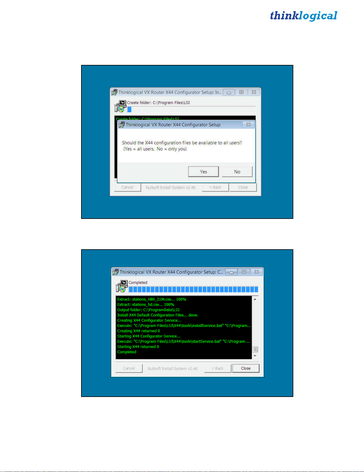
If this is the first installation, then leave all the checkboxes checked. However, if this is an update from an
earlier version, you can safely uncheck the first two boxes for “Install Python2.6” and “Install Python
win32 extensions” as they will already be on your computer. Click Install.
Click “Yes”.
Please note the last five rows. The fifth from the bottom should read “Creating X44 returned 0” and the
second from the bottom should read “Starting X44 returned 0”. If either of these lines does not show
“returned 0”, then a problem was encountered during installation and X4 will not work.
X4 Configurator Manual 7 October, 2012
Page 8

Firewall Considerations
If your firewall is enabled, you may require some additional configuration. By default, firewalls block
connections on port 80, which is the standard for web communications. The easiest/fastest way to get
around this is to disable the firewall, but this is not always acceptable. If you need your firewall enabled,
you must open port 80.
In addition, Thinklogical VX routers periodically broadcast their connection status via UDP on port
17564. Firewalls normally block this as well, so the firewall requires a new inbound rule to let the status
broadcast in.
NOTE: You may need administrator privileges to install this software and make the required
changes to the firewall. Please speak to your network administrator or refer to your firewall program
documentation for more information.
X4 Configurator Login
X4 is accessed via a web browser from any computer on the same network as the X4 server. Some of the
administrative pages can be demanding on the JavaScript engine on the browser, so if it’s running too
slowly on your current browser, please try Google Chrome.
Set the browser’s URL to the IP address of your server to load the page. Logins are required by default,
so if this is your first access you may see this:
The default user name is “admin” and the password is “admin” (You can change this later.)
X4 Configurator Manual 8 October, 2012
Page 9
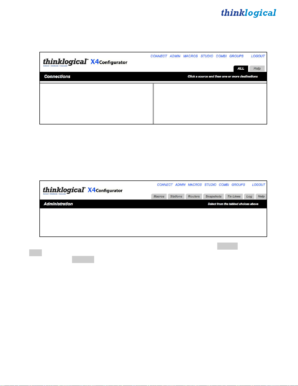
Introduction
The first time you log in, the
CONNECT
page will load automatically.
This page is one of the pages used for connecting sources to destinations. However, the first time the
program is accessed it will be unpopulated.
There are blue names across the top of the page along the right side, starting with
with
LOGOUT
The first step will be to click the
. These are links to the other pages. This document will describe each of them as needed.
ADMIN
link. A new page will load that looks like this:
CONNECT
and ending
Above the black stripe are tabs for the administrative functions beginning with Macros and ending with
Help. Clicking on a tab will highlight it and load the settings for modifying the settings associated with
that tab. Click the Routers tab and continue to the page.
X4 Configurator Manual 9 October, 2012
Page 10
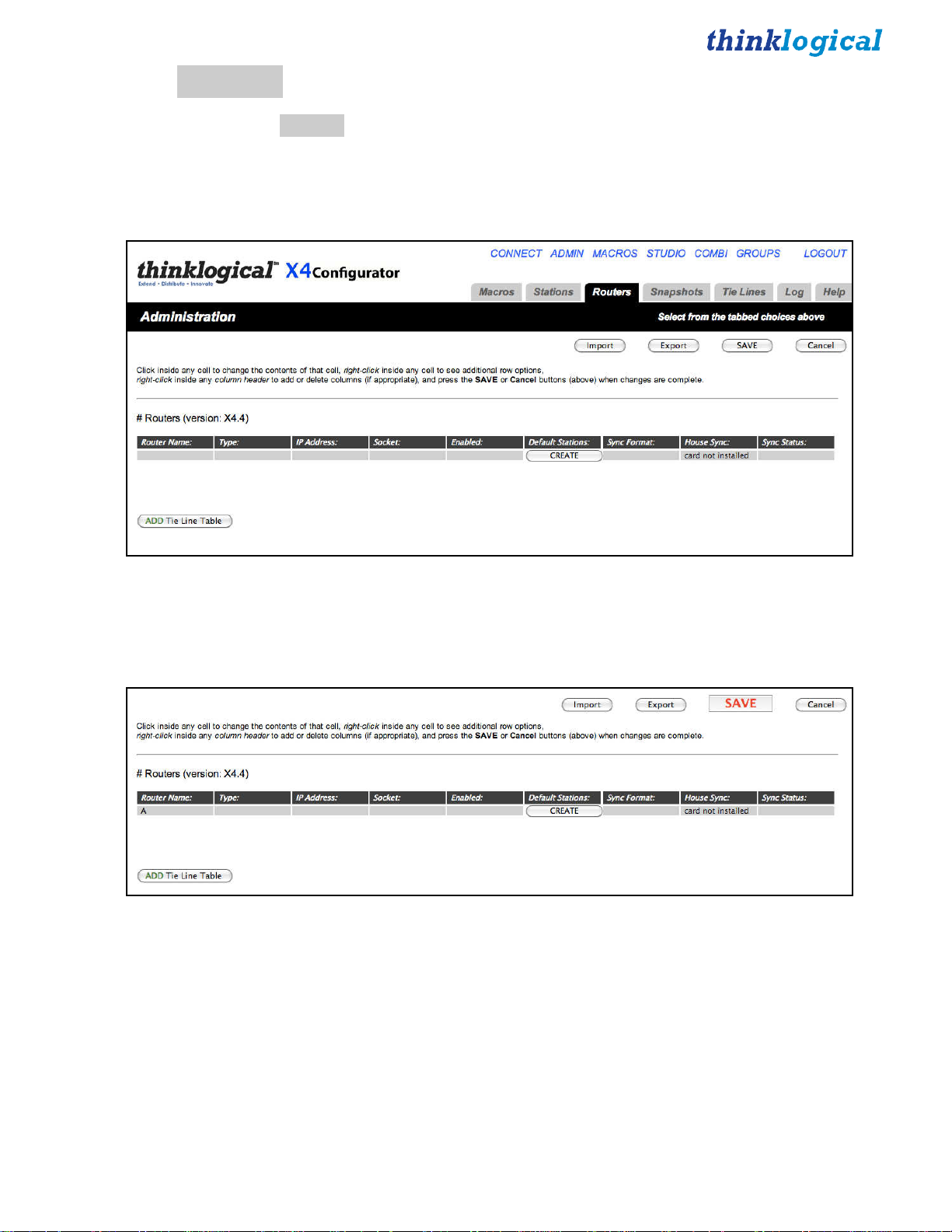
ADMIN:
On the
Routers
ADMIN
page, the
Routers
tab allows you to configure X4Configurator for your routers. The router
(or router simulator program) must be already running and on the network. The setup process will attempt
to communicate with the router over the network and will fail if the router does not respond or is a
different type than the one you selected.
If this is a fresh install, there will be no routers declared yet. Click on the gray row beneath the column
header “Router Name:” and enter the name you will use for your router. If you click on the entries for the
remaining fields, you will be offered pop-up lists of choices. For this example, we will use a VX80.
X4 Configurator Manual 10 October, 2012
Page 11
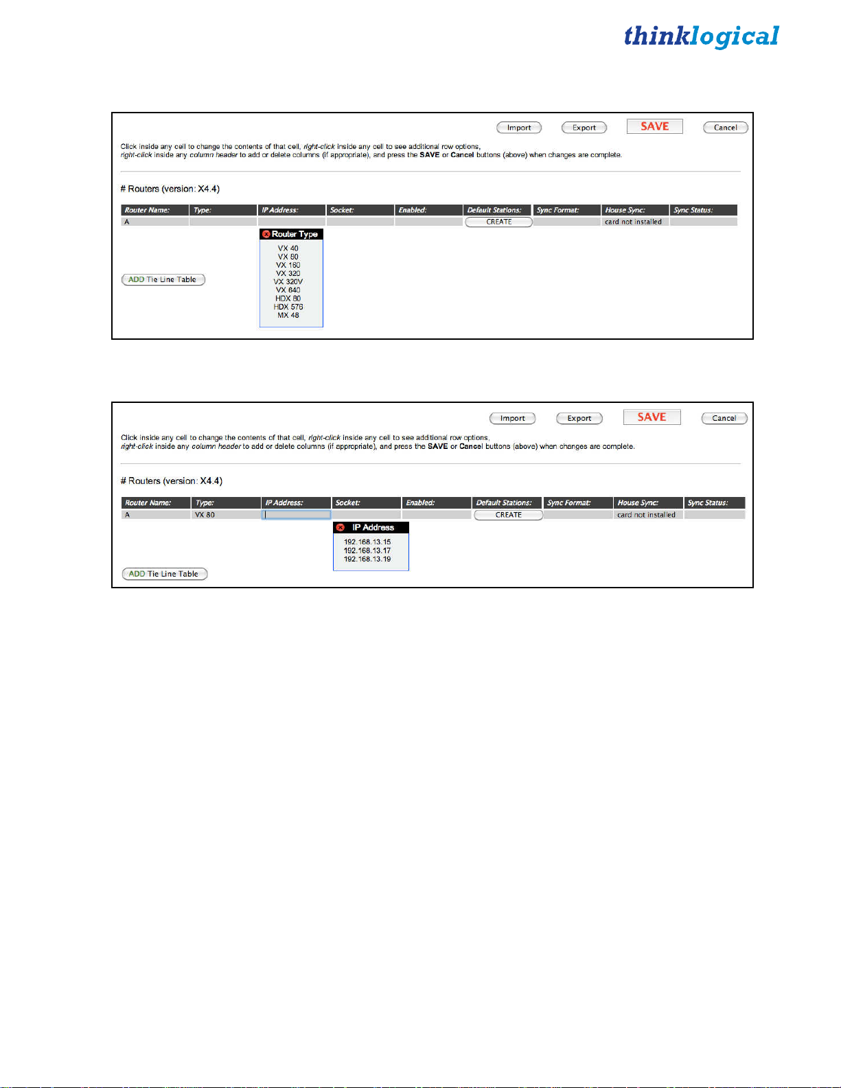
Next, choose the router type by clicking in the 'Type' gray box.
Clicking in the IP Address:, Socket:, and Enabled: boxes will pop up choices for each of those fields.
When the router's name, type, IP address, socket, and enabled fields are complete, click the SAVE button
near the top right corner.
X4 Configurator Manual 11 October, 2012
Page 12
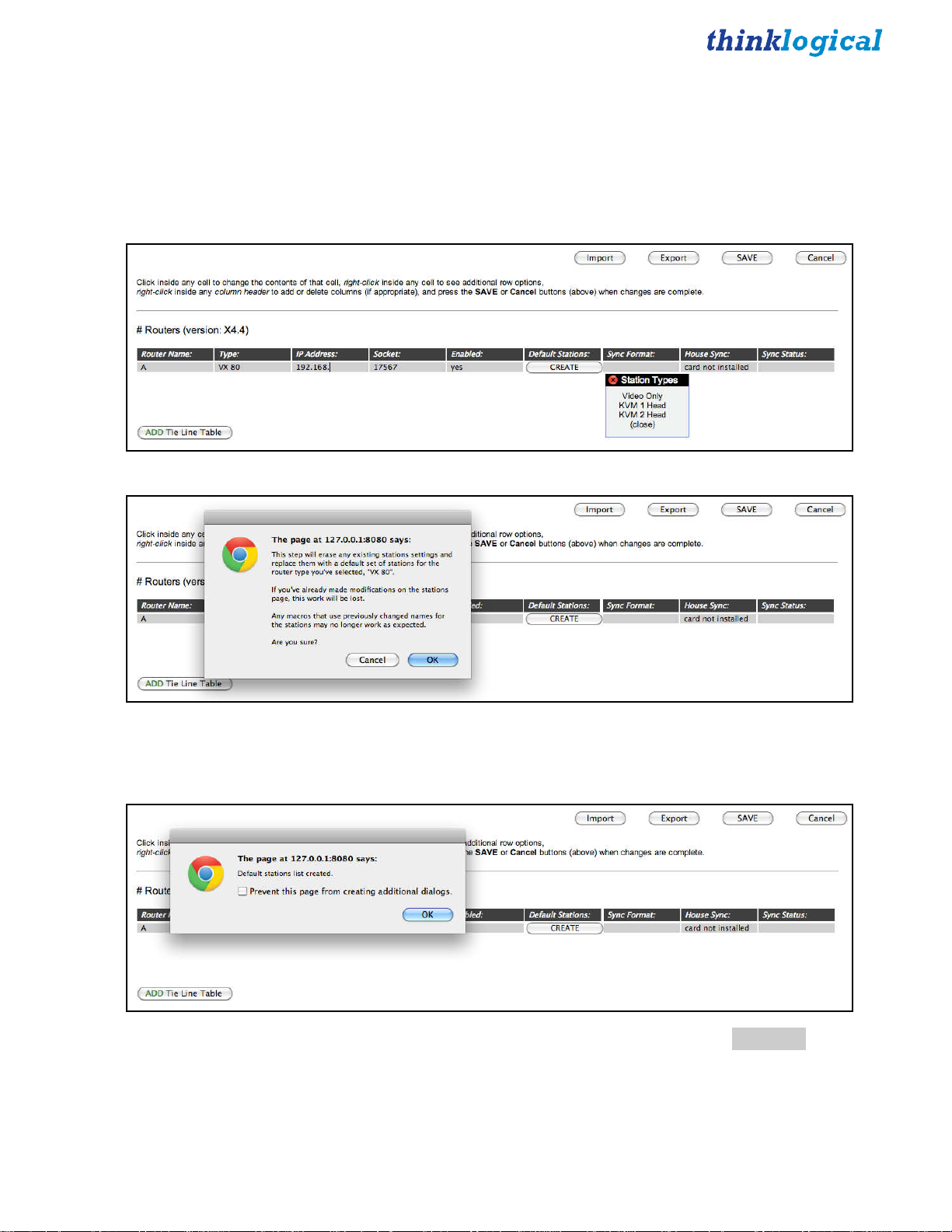
Next, we will create some “stations.” Stations are source and destination elements that can be
connected. A station can contain a single port or multiple ports, and a single station can include ports
located on multiple routers.
For this example we will create a default set of stations that has a single video head with keyboard and
mouse (KVM 1 Head).
Click the 'CREATE' button under Default Stations:, then click on 'KVM 1 Head'.
Here is a last chance - if you’ve already configured your stations, you may not wish to overwrite them
with the defaults. Since we haven’t created any yet, click OK
The new stations have been created. We can inspect and change them by clicking the Stations tab
.
.
X4 Configurator Manual 12 October, 2012
Page 13
ADMIN:
As we’ve seen before, stations are the sources and destinations that can be connected together. Click the
ADMIN
Stations
link and then the
Stations
tab to get to the stations page.
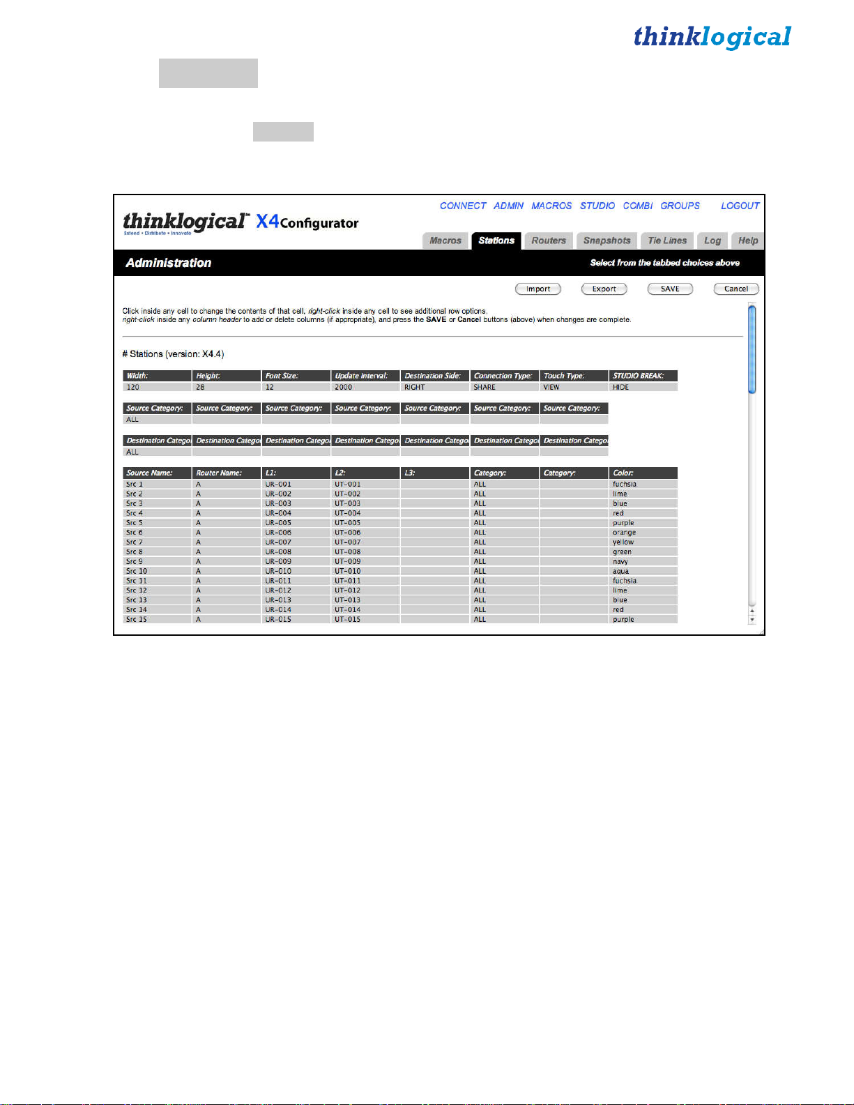
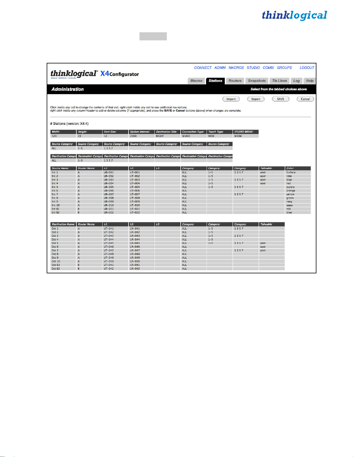
This page is designed to operate like a simple spreadsheet. Any value can be changed by clicking in it and
typing a new value. Values can be copied and pasted, but only one at a time.
For more powerful editing options, see the chapters Import/Export Station Configurations and
Configuring via Spreadsheet.
The first table, starting with the column “Width”, sets up values that will be common for all the stations
on certain pages. We can ignore it for now.
The second and third tables are also safely ignored for now. We will return to them later.
The fourth table, starting with the column header Source Name: defines the source stations. Since we
created a default set with a single video and a data return channel for a VX80 named “A”, we will find
sources named Src 1 through Src 40. Each source will have two ports; the first for video and the second
for the data return.
X4 Configurator Manual 13 October, 2012
Page 14

Source stations can be added or deleted by right-clicking on an existing station row and selecting Insert,
Append, or Delete from the pop-up menu. Existing station rows can be copied and pasted using the same
menu.
Scrolling down the page, we find the next and final table, which is for destination stations.
X4 Configurator Manual 14 October, 2012
Page 15

Scrolling back up to sources, it’s time to examine the fields in depth.
The first source station is named “Src 1”. It has ports that are attached to the router named “A”. The ports
are named L1:, L2:, and L3: for convenience (since they match the first video, data return, and second
video fiber names on Thinklogical fiber extenders), but the names are not important. Only the router
name that precedes them and their order matter.
The port names require some explanation:
Thinklogical’s VX160 and VX40 routers have boards that are labeled “Upstream” or “Downstream”. The
VX320 has two separate card cages in the same enclosure, “Up” and “Down”. (Please see the VX Router
Manual for a view of the card cages and card designations.)
The port names are very specific and unambiguously define a unique SFP and the Transmit “T” or
Receive “R” port within that SFP. Ports in the “upstream” cards on VX160 and VX40 routers or the “up”
card cage on the VX320 start with “U” and ports in the “downstream” cards (VX160, VX40) or “down”
card cage (VX320) start with “D”.
Cards in Thinklogical’s other routers (VX80, VX320 Video, MX48, VX640, HDX80, and HDX576) do
not have “upstream,” “up,” “downstream,” or “down” designations. However, for consistency, the ports
in those routers are always preceded by “U”.
Our example of Src 1 on a VX80 has two ports. The first is port UR-001 and it is being used for video.
●
“U” is because this port is on a VX80 (and they are all “U”)
●
“R” means this is receiving a signal from the TX extender (video in this case)
●
001 means this port is on the very first SFP in the card cage (bottom, left)
The second port on Src 1 is UT-001 and is for the data return channel (USB, serial, DDC, etc.)
●
“U” is because this port is on a VX80 (and they are all “U”).
●
“T” means this is transmitting a signal to the TX extender (data in this case).
●
001 means this port is on the very first SFP in the card cage (bottom, left).
L3: is empty on these sources because we created a default set with single video and data return. If your
sources have two heads, the second video will go in the L3: column.
The next two columns are labeled “Category”. These allow the administrator to organize the sources and
destinations so that they can be organized and viewed together or separated as appropriate. We will return
to this topic later.
X4 Configurator Manual 15 October, 2012
Page 16

Scroll down to the lower half of the stations page to find the destinations.
The default stations set up for single-headed KVM use half the SFPs as sources and half as destinations.
Since there are eighty (80) SFPs, each with its own receiver and transmitter, there are eighty receiver
ports and eighty transmitter ports. Every receiver port and every transmitter is completely independent.
With the exception of the VX160, any receiver port can be connected to any transmitter port.
In Dst 3, the first port is UT-043 and it is being used for video.
●
“U” is because this port is on a VX 80 (all “U”).
●
“T” means this is transmitting a signal from the router to the extender (video in this case).
●
043 means this port is on SFP number 43.
Similarly, the second port is the same as the first, with the exception of the “R” replacing the “T,” since
this port will receive the data return from the receiver extender.
Therefore, when told via a browser page to connect Src 1 to Dst 3, the router will
●
Connect UR-001 to UT-043 (for the video).
●
Connect UR-043 to UT-001 (for the data return).
At this point the two stations are considered connected.
NOTE: If the source and destination each have two heads, then the router will connect all the R
ports from the source to all the T ports on the destination, and all the R ports on the destination to all the
T ports on the source. Blank entries will be skipped. If a two-headed source is connected to a single-head
destination, the first head of the source will be connected and the second will not. If a single-head source
is connected to a double-head destination, the second head of the destination will be disconnected.
X4 Configurator Manual 16 October, 2012
Page 17
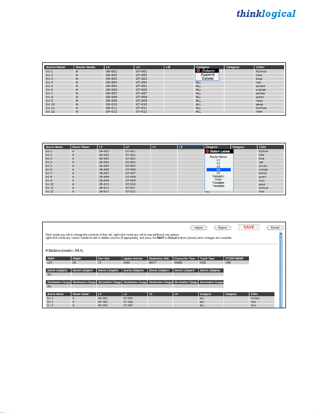
Adding New Ports
If your sources and destinations have more than two heads, additional port columns can be added. Right
click on the existing L3: column header and select Append from the Column pop-up.
A new L3: column appears. Left click on the new L3: header and select L4:
The column will be renamed.
However, we don’t need extra signals right now, so click the Cancel button (not SAVE).
At this point, we have a router and some stations defined, so X4 can make connections between sources
and destinations. To see how this is done, proceed to the CONNECT Page in this manual.
X4 Configurator Manual 17 October, 2012
Page 18
Import/Export Station Configurations
Internally, all configurations for stations and routers are maintained in Comma Separated Value format,
or CSV files. For complex installations, it is often easier to modify these stations and router configuration
files using a spreadsheet program.
To save a local copy of the stations.csv file, select
ADMIN Stations
and click the “Export” button. A copy
of the file will be downloaded through the browser’s normal file download function.
NOTE: In file names for stations, the name must start with “stations” and end with “.csv”. The part
of the file name between “stations” and “.csv” is ignored, so the administrator can use the middle of the
file name for any identifying information.
For example, the first time Windows downloads the “stations.csv” file into the download directory, it will
be saved as “stations.csv”. Future downloads may be named “stations (2).csv”, etc. The administrator
may decide to rename their saved “stations.csv” as “stations-phase-1.csv”, and X4 will still upload it and
save it as “stations.csv” internally.
This allows the administrator to maintain multiple stations and routers files with their own names.
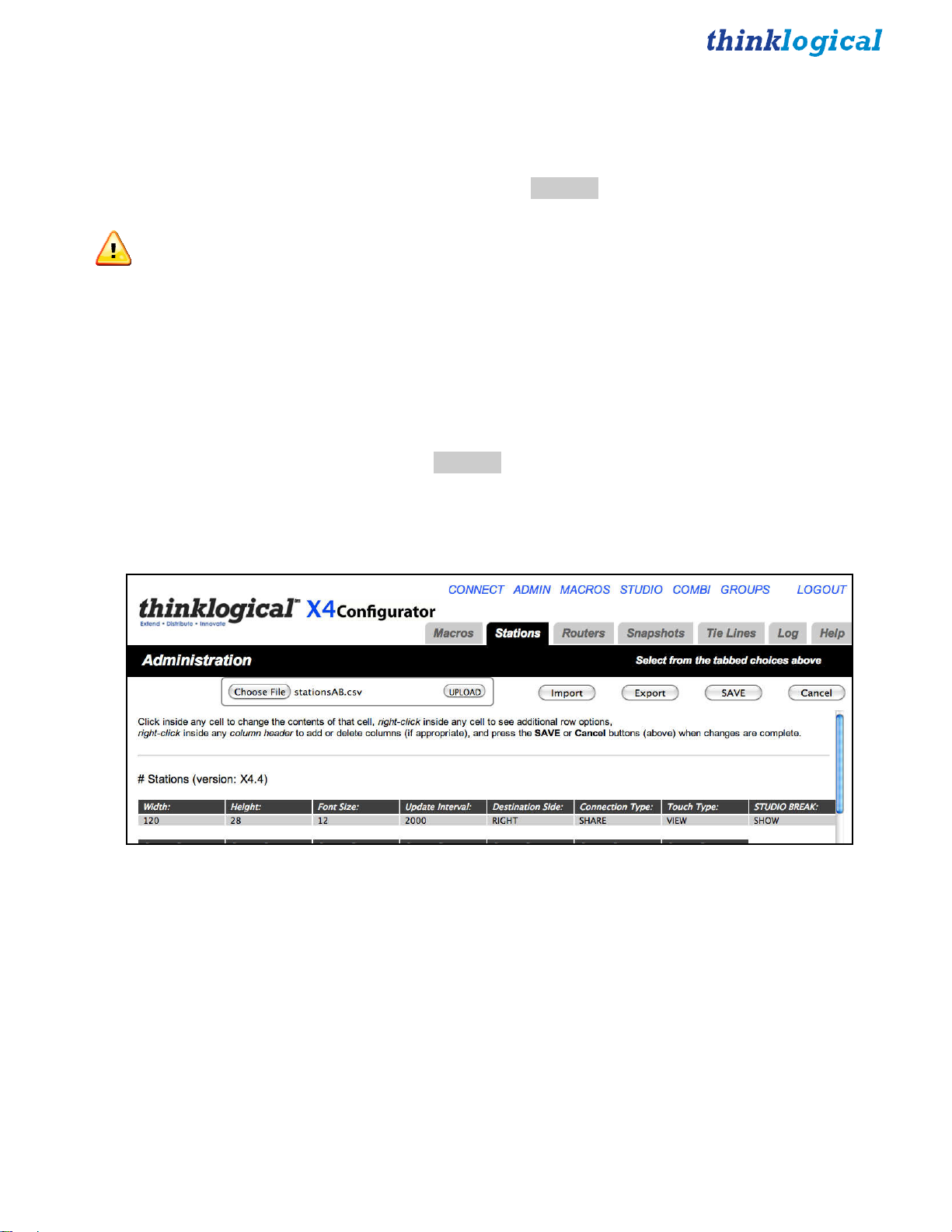
To upload the stations.csv file, select
ADMIN Stations
and click the “Import” button. The web browser
will pop up a file browser window and let you select the file to be uploaded. Select it and the file browser
will close. Now click the “UPLOAD” button and the file will be transmitted to the server.
X4 Configurator Manual 18 October, 2012
Page 19
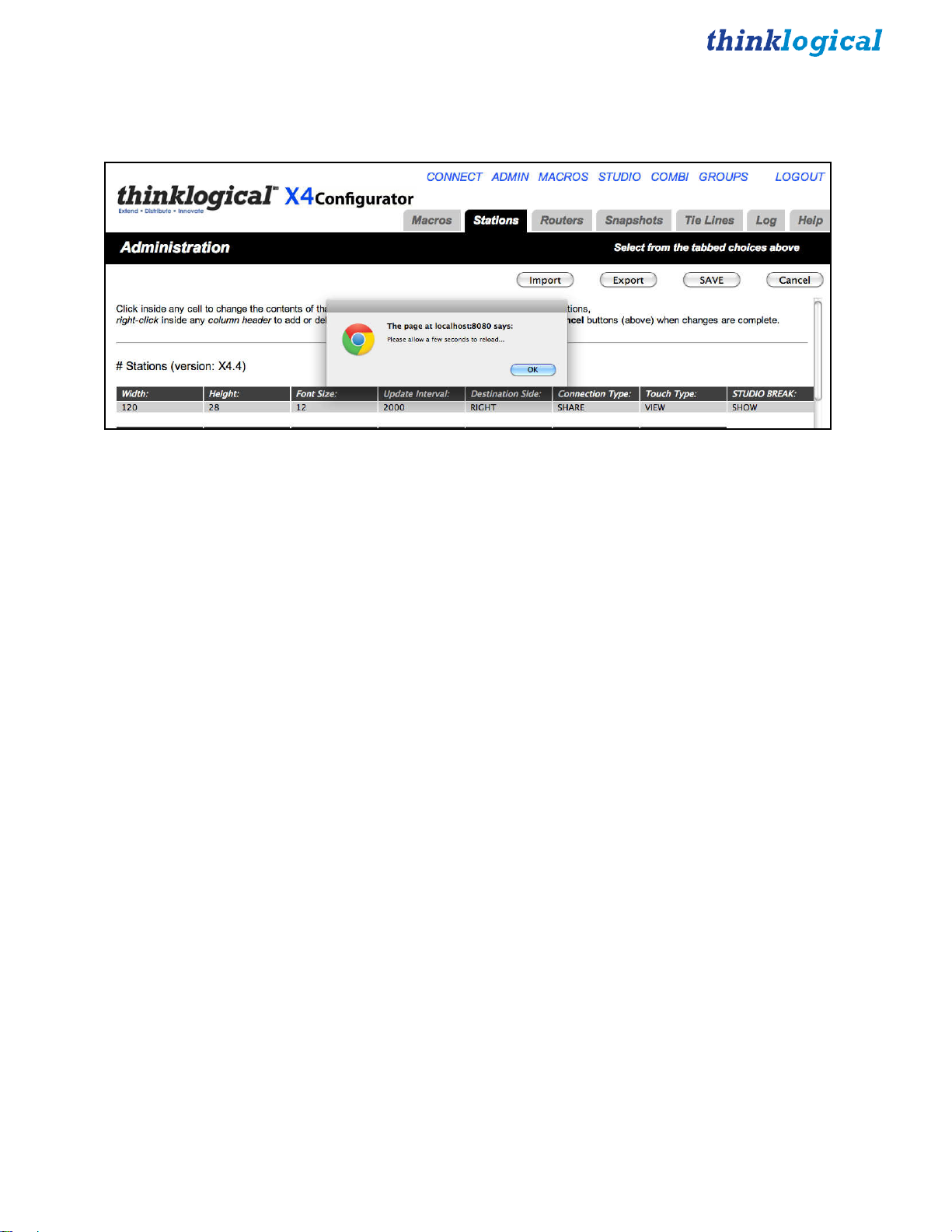
After the upload starts, the web browser will pop up an alert “Please allow a few seconds to reload...”.
Click the OK button and the page will reload.
X4 Configurator Manual 19 October, 2012
Page 20
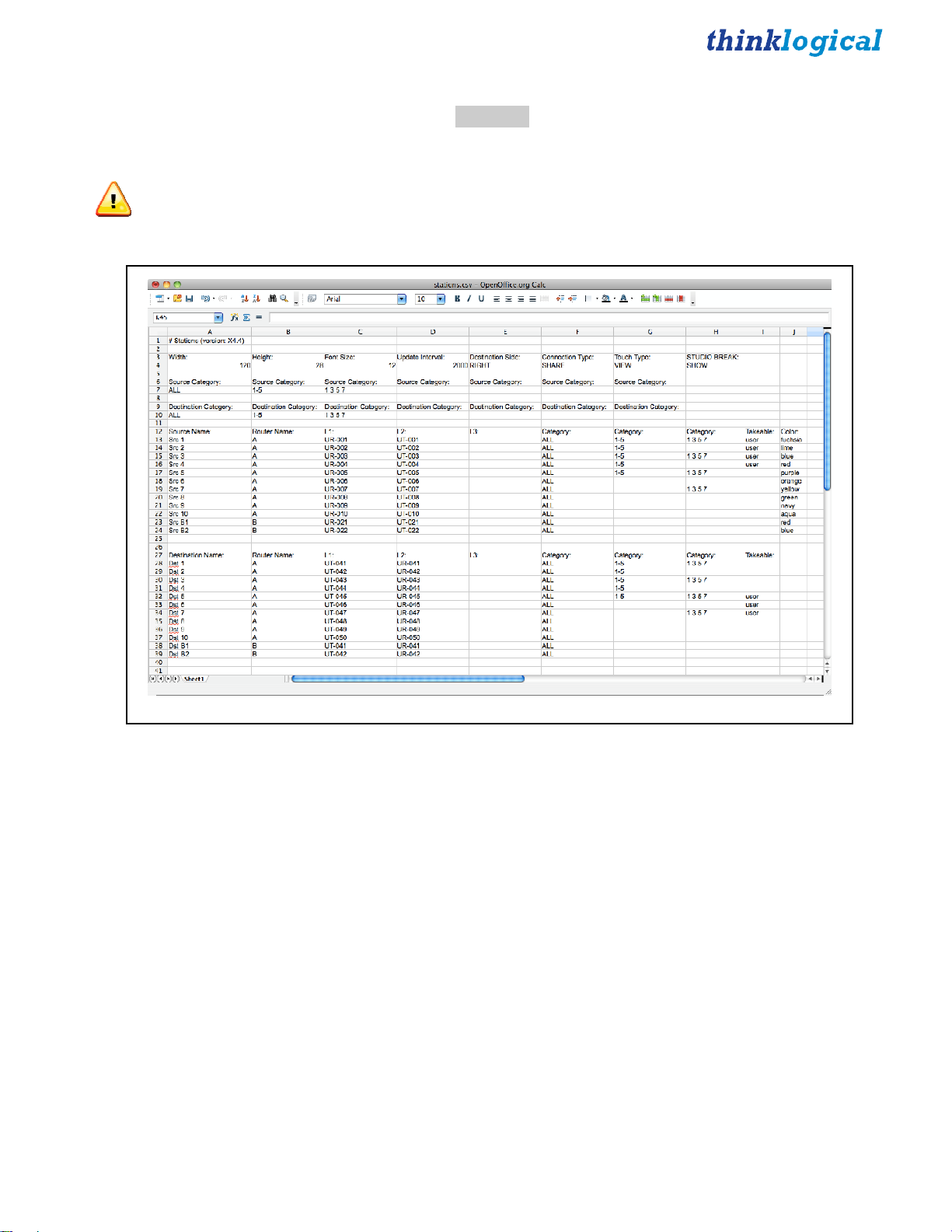
Configuring via Spreadsheet
Configuring many stations using X4’s ADMIN: Stations page can be slow. An alternative is to export
the stations file (as described in Import/Export Station Configurations and then make changes using a
spreadsheet program like Excel or Open Office.
NOTE: It is important to save the file as CSV after editing and always keep an unedited backup.
As shown, we have removed all the sources after “Src 10” and added three new ones that refer to router
“B.” Don’t forget to insert a heading in the Category column so these new sources will be found.
The process is the same for destinations named “B1” and “B2.”
X4 Configurator Manual 20 October, 2012
Page 21
Save this file with a new name and upload it using the instructions in Import/Export Station
Configurations. Once the ADMIN: Stations page reloads there will be a shorter page with some new
sources and destinations on router B as well as the previous ones from router A.
X4 Configurator Manual 21 October, 2012
Page 22

ADMIN:
“Tie lines” are fiber interconnects between routers that allow sources on one router to be seen at
destinations on another.
Thinklogical’s implementation of tie lines can automatically allocate, utilize, and deallocate tie lines as
necessary, even creating multi-hop connections utilizing intermediate routers when no direct paths are
available.
Tie lines are created on the ADMIN: Routers page. First, we’ll need more than one router. Right click
on the existing router description to activate the Row pop-up, and then select Append from the list to add
a new row.
Tie Lines
Enter the information for the second router as described in ADMIN: Routers
*Note: The IP addresses shown in this manual are not the defaults used in most installations. Please
insert your own addresses where appropriate.
Click SAVE when done.
.
X4 Configurator Manual 22 October, 2012
Page 23

Next, create the Tie Line Table. This is done by clicking the “ADD Tie Line Table” button on the bottom
left. When clicked, it will insert a headers and a single, blank row for the first tie line (and replaces the
Add Tie Line Table button with a REMOVE Tie Line Table button).
Add the values for the first tie line. The start port is where the signal will exit the start router and will be a
Transmit. The end port is where the signal enters the end router and will be a Receive port. Duplex means
there is a second fiber for the return channel, so since duplex is true in this case, it would be on router A
at port UR-071 and router B at UT-061.
The easiest way to add new tie lines is to:
1. Right click on the first one and select Copy.
2. Right click on the first one again, select Append.
3. Right click on the new, blank line and select Paste.
The choice of each tie line name is up to the administrator. It is used to uniquely identify the tie line to the
program and for diagnostics as we will see later. Make sure that the Duplex and Automatic columns are
set to “yes”.
In this case, we have created three duplex paths from A to B and one from B to A. Click SAVE when
done
.
Next, we need to create stations on both routers. If you are using one of the default files created
automatically by X4, it probably has many more stations than are needed. Use the ADMIN Stations
Export function to save a copy of stations.csv, and edit it using a spreadsheet program like Excel or Open
Office.
X4 Configurator Manual 23 October, 2012
Page 24

(The chapters on
Import/Export Station Configuration
and
Configuring via Spreadsheet
, show how
to create additional source and destination stations on the second router. The rest of this chapter uses the
stations created from those chapters.)
Using and Monitoring Tie Lines
In the chapters and , we modified our stations file. It now looks like this, with sources and destinations
from both routers A and B.
Select CONNECT from the links across the top. There will be two new sources and two new destinations.
X4 Configurator Manual 24 October, 2012
Page 25

Select one of the older sources from router A and then a destination on router B. For this example we’ll
use Src 3 and destination Dst B2.
Note that there is no obvious indication that the connection required tie lines. But if you select the
ADMIN link and the Tie Lines tab, you will see the tie line in action.
This page shows that the source, “Src 3”, is entering router “A” and output through the tie line named
AB-1 to enter router “B” and finally being sent to destination “Dst B2”.
X4 Configurator Manual 25 October, 2012
Page 26

Clicking directly on the tie line icon for AB-1 will pop up some brief information about that tie line.
As you can see from this graphical representation and from the earlier tie line table on the ADMIN:
Routers page, we have three tie lines leading from A to B and only one from B to A. To see what
happens when the tie lines become “oversubscribed,” go back to the
CONNECT
page and connect a
source on B to a destination on A.
X4 Configurator Manual 26 October, 2012
Page 27

Return to ADMIN: Tie Lines.
Note that only the tie line from B to A is in use. Now return to the CONNECT page (for which you
probably have kept a browser tab open) and connect another B source to another A destination.
The red message “No path available” will appear for a few seconds and then disappear whenever there are
not enough tie lines to complete the desired connection.
X4 Configurator Manual 27 October, 2012
Page 28

Here is how the same condition looks on the
STUDIO
and
COMBI
screens.
X4 Configurator Manual 28 October, 2012
Page 29

ADMIN:
A “Snapshot” is a complete record of all the active connections on all the routers at the time it was
recorded. It is a simple way to return all the connections to a previous state.
Snapshots are created and recalled from the
The buttons that begin with xbk_ are created automatically during an operation and are the results of the
last ten actions (connects or disconnects). The names always begin with “xbk_’ followed by the day of
the year, hour, minute and second. To go back to a previous time, click the button for that time.
Snapshots
ADMIN
page
Snapshots
tab.
A confirmation dialog will appear with one last chance to cancel.
Click OK and the action is performed.
X4 Configurator Manual 29 October, 2012
Page 30

To create a new snapshot with your own title, either select the most recent automatic snapshot from the
drop-down list and give it your own name or pull down to the last option and select “Create New
Snapshot”.
To give it a new name, click the “Press to Record” button and the new snapshot is created.
NOTE: There is one last important point to remember about snapshots:
When a snapshot is executed, each router will first disconnect every port and then proceed to reconnect
only the ports that were connected when the snapshot was recorded. This means that every screen will
first go dark and then be reconnected the way the snapshot recorded it.
X4 Configurator Manual 30 October, 2012
Page 31

ADMIN:
A log file is kept of all user and system maintenance activities. To see it, go to the
Log
tab.
Log
ADMIN
page and the
X4 Configurator Manual 31 October, 2012
Page 32

ADMIN:
The final tab is context sensitive “Help.” A short help pop-up is available for every tab on the
page and also on the
Help
CONNECT
page.
ADMIN
X4 Configurator Manual 32 October, 2012
Page 33

CONNECT Page
Click the
CONNECT
link at the top of the page.
Sources are on the left, destinations on the right. Click Src 1 and it will highlight in light blue.
X4 Configurator Manual 33 October, 2012
Page 34

Now that Src 1 is selected, click Dst 3.
Now Dst 3 shows that Src 1 is driving it. The disconnect X in the center takes on the color of the source’s
top border and the name “Src 1” appears on the right side of the destination. The small mouse icon
indicates that the data return from Dst 3 is driving Src 1.
On the left side, the rectangle for Src 1 gets a dashed, upper border to show that it is in use.
By mousing over Src 1 or Dst 3, the dashed border on the source will turn solid and all destinations being
driven by it will have their top, gray borders become thicker and turn the color of the source that’s driving
them.
By default, when additional destinations are connected to a previously connected source, they will all
SHARE the video from the source, but only the last one connected will have control of the mouse (as
shown by the icon). SHARE will be explained below.
Here we have clicked Dst 4, which will now show the same, Src 1 video as Dst 3. But as the mouse icon
shows, only the last destination clicked, Dst 4, is driving the data return back to the source.
Clicking a destination’s colored X will disconnect that destination and clicking the X at the right side of
the source will disconnect all the destinations connected to that source.
X4 Configurator Manual 34 October, 2012
Page 35

As stated above, when new destinations are connected to an already connected source, they will all
SHARE the video and only one will have the data return. But SHARE is only one of three connection
modes:
●
SHARE: multiple video connections, last connection has data return
●
TAKE: each newly connected destination removes the video from all previous destinations and
the new destination also has the data return
●
VIEW: each newly connected destination can view the video but will not take the data return.
To change the connection mode, return to ADMIN: Stations.
Click SHARE under Connection Type: in the first table.
Mouse over and select TAKE.
If you next click the SAVE button, the CONNECT page will be in TAKE mode until you change it again.
For now, leave it in SHARE mode.
While on the ADMIN: Stations page, examine the second and third tables that start with “Source
Category” and “Destination Category.” By default these rows will only have one entry: ALL.
X4 Configurator Manual 35 October, 2012
Page 36

Station Categories
Return to the
CONNECT
page.
There are two tabs on this page:
collections, go back to the page.
ALL
and
Help
. If you want to break up the stations into smaller
Here is added a new entry to both the source and destination categories, “
the
CONNECT
page.
1-5
”. Click SAVE and return to
X4 Configurator Manual 36 October, 2012
Page 37

Click on the new tab
1-5
next to
ALL
.
The tab is selected, but there are no sources or destinations.
Go back to the ADMIN: Stations page:
Add “1-5” to the second Category column for the first five sources. Then scroll down to the destinations.
Add “1-5” to the second Category column for the first five destinations. Then be sure to click the SAVE
button.
X4 Configurator Manual 37 October, 2012
Page 38

Go back to the
CONNECT
page and click the
1-5
tab.
Now clicking the
Stations can belong to multiple categories. To add a new category, return to
1-5
tab shows the sources and destinations included in that category.
ADMIN Stations
.
There are currently only two Category columns. To add a new one, right click on the top of the last
Category (where it says Category:).
X4 Configurator Manual 38 October, 2012
Page 39

A pop-up window will appear. Select Append.
There now are three Category columns. Add “1 3 5 7” to some source rows. Next, add it to the Source
Category and Destination Category tables (above). Then scroll down to the destinations
Right click the last Category header, select Append and add the new Category. Now add the new
category to some sources as shown below.
Go back to the CONNECT page to see the results.
X4 Configurator Manual 39 October, 2012
Page 40

MACROS Page
A macro is a sequence of operations that the user can create, save, and recall to repeat steps that will be
executed frequently. They can be restricted to specific user groups or made available to all groups.
The easiest way to create a macro is to perform the desired steps and then let the
what you’ve done and how to save it.
Use the CONNECT, STUDIO, or COMBI pages to make and/or break some connections and then select
the MACROS link from the top of the page.
Initially, this page is blank since no macros have been created yet.
MACROS
page tell you
Click the “Macro from History” button on the right side of the black bar.
X4 Configurator Manual 40 October, 2012
Page 41

The page now shows the most recent connect and disconnect operations that have been performed at this
location by this user. Check the rows that should be part of a macro (in this case by using the “Select All”
button) and enter a new name for the macro in the “New Macro Name?” field.
Next click the “SAVE” button and wait for the update. After a few seconds, the new macro will appear in
its own box on the MACROS page.
Clicking this button will execute the macro immediately.
Macros can also include other macros. Click the “mac 1” button, go to the CONNECT page and add one
more connection.
X4 Configurator Manual 41 October, 2012
Page 42

Now return to the MACROS page and click “Macro from History”.
Select the last two steps. Give this new macro a name and click SAVE.
“mac 2” will first execute “mac 1” and then perform any additional steps.
Macros are also available on the STUDIO page where they are called “Sequences”.
To execute a macro or “sequence” on the STUDIO page, select it and it will highlight. Then click the
TAKE button to execute it.
X4 Configurator Manual 42 October, 2012
Page 43

The STUDIO page has another feature involving sequences: right click on one and it will display the
actions that will be performed.
Left click on the sequence’s description to close it.
X4 Configurator Manual 43 October, 2012
Page 44

Creating/Editing/Deleting Macros
Go to the ADMIN page and select
Macro” drop down on the left side of the page.
Macros
from among the tabs. Select “mac 1” from the “First Select
From this page the macro can be renamed, modified, or deleted.
X4 Configurator Manual 44 October, 2012
Page 45

To add a step, right click on the row either above or below the desired point in the sequence. In this
example we have chosen to insert a step before the last step.
Left click on the empty field below Action and you will be given a choice of Actions.
X4 Configurator Manual 45 October, 2012
Page 46

Select VIEW and then click on the empty field below Destination to call up the pop-up of destinations.
And finally, do the same for the source.
If the name is to be changed, it will be done in the field to the right of “New Name? (or leave
unchanged)”
X4 Configurator Manual 46 October, 2012
Page 47

Finally, there is a row of Group headings that decide which users can see and execute this macro. The
admin group can see all of them, but if other groups need to see them, they must all be listed. For this
example we’ve changed “undefined” to “user” so user can see it.
Click SAVE when all changes are complete.
X4 Configurator Manual 47 October, 2012
Page 48

STUDIO
Page
On the
sources are on the right and destinations on the left. Notice that the categories already created appear at
the top of the page, but that the destination category and source category can be selected independently,
as shown below.
STUDIO
page, the sources and destinations are reversed from the default
CONNECT
page. Here,
X4 Configurator Manual 48 October, 2012
Page 49

To perform operations on this page, click the ALL button for both Source and Destination categories (top
left and right) to show all the stations. To make a connection, select a destination and a source (in either
order) and then select from the connection types along the bottom (TAKE, (VIEW), SHARE).
Here is selected Dst 6 and Src 4. Notice that Dst 6 appears in a window at the bottom left before we’ve
performed any action to make sure we’re affecting the correct destination.
X4 Configurator Manual 49 October, 2012
Page 50

Click the TAKE button (blue, bottom, next to the DESTINATION window) and the connection is made.
As mentioned earlier, the TAKE type connection performs differently than the SHARE and (VIEW).
Leave Src 4 selected, select destination Dst 5 and click TAKE.
Now Dst 5 has Src 4 and the space above Dst 6 is blank, which signifies no connection.
X4 Configurator Manual 50 October, 2012
Page 51

By default, there is no way to disconnect stations on the STUDIO page.
If necessary or desirable, there is a way to add one.
Using the browser’s back key, go to the
page. In the first table on the page, click the field below the STUDIO BREAK: header.
ADMIN Stations
X4 Configurator Manual 51 October, 2012
Page 52

Select SHOW, click the SAVE button and select the STUDIO link. There will be a new, red “BREAK”
button at the bottom. Select Dst 5, click BREAK and the destination will be disconnected.
The STUDIO page supports TAKE, SHARE, and (VIEW) connections. The use of parentheses around
VIEW is deliberate - parentheses around the source name in the destination box show that the source is
being viewed but does not have the return channel and cannot control the keyboard/mouse. If an operator
wanted to see the video from a source without disturbing someone already using it, they would have to
select the source and their own destination and then click (VIEW). It would then appear as below:
The operator has selected Src 1 and Dst 6 and clicked the (VIEW) button. Now the video from Src 1 is at
both Dst 3 and Dst 6, but only Dst 3 has control of the keyboard/mouse.
X4 Configurator Manual 52 October, 2012
Page 53

SHARE allows cooperative viewing. If the operator at Dst 6 clicked the SHARE button, both Dst 3 and
Dst 6 would still have the video, but the keyboard/mouse control would move to Dst 6 and Dst 3 would
show Src 1 in parentheses (as below).
At this point, Dst 1 could take back control by selecting Dst 1 and clicking SHARE.
TAKE removes the video from any destinations that are currently viewing it and also takes control of the
keyboard/mouse.
The LOCK and UNLOCK buttons allow the user to restrict a source and destination. If a connected
destination is selected and the the LOCK button clicked on, both that destination and the source that is
feeding it become locked and unavailable for other connections. They turn red to show this status and will
not allow any connection changes to the destination or the source until the destination is unlocked
In this capture, Dst 3 has been selected and the LOCK button clicked. Both are now red.
X4 Configurator Manual 53 October, 2012
Page 54

If an operator attempts to connect Src 1 with another destination, Dst 6 in the example below, the
program will display a notice that no new connections or disconnections involving this source and this
destination will be allowed until the destination is unlocked from the source.
Selecting Dst 3 and clicking the blue UNLOCK button will release it.
NOTE: The
STUDIO
page does not have any clear way to move to other screens. This is intentional
- this page is designed for users and operators who will seldom need any other page. The only way to get
to other pages are either the browser’s back button or by changing the browser’s URL to another page.
X4 Configurator Manual 54 October, 2012
Page 55

COMBI
Select
last on the
COMBI
STUDIO
Page
from the links across the top. (You may need to use the browser’s back button if you were
page.)
This page combines features from the
size displays and touch-screens.
X4 Configurator Manual 55 October, 2012
CONNECT
and
STUDIO
pages and is designed to work on both full
Page 56

As in the
STUDIO
page, the user can select a source or a destination first. Once a source and a destination
have been selected, the user can connect using the buttons across the bottom right.
One difference from the STUDIO page is that on this page the source icons also show which
destinations they are driving. In this example, Src 1 (top left) shows Dst 6* and Dst 3 in its window.
The asterisk after Dst 6 means that it has the return channel and has control of the keyboard/mouse. In the
destinations section at the bottom half of the page, both destinations show Src 1 as their source. But Dst
3 appears in parentheses, indicating it is video only, and Dst 6 has the asterisk, indicating that Dst 6 has
control.
X4 Configurator Manual 56 October, 2012
Page 57

The tabs below the SOURCES and DESTINATIONS banners (ALL, 1-5, 1 3 5 7) are the same as the
categories in the
STUDIO
page.
STUDIO
page and the LOCK and UNLOCK functions also work the same way as in the
There is also a COMBI-M Page. It includes a Macros button at the bottom, right corner that links to the
MACROS page. In all other ways, however, it is the same as the COMBI page and is used mostly for
demonstration purposes.
X4 Configurator Manual 57 October, 2012
Page 58

Multiple Browser Tabs
When switching back and forth between X4 pages, it is often convenient to make use of the browser's
ability to maintain multiple open tabs. This way an administrator can keep the
the
CONNECT
page on another tab, and so on.
ADMIN
page on one tab,
At the top of the image below, the browser shows tabs for
COMBI, ADMIN, STUDIO
available at the same time for easy access to whichever page is needed.
and
CONNECT,
all
X4 Configurator Manual 58 October, 2012
Page 59

GROUPS Page
NOTE: Sometimes it is important to restrict access to assets and control pages. Thinklogical’s X4
supports this requirement through the use of user groups, or just groups.
Use the browser’s back button (or one of the tabs you’ve opened for easy access to different pages) to get
back to a page with links across the top and select the
GROUPS
link.
This page defines users, groups and the access granted to them. There are four tables on this page which
will be indexed by the leftmost header for each table.
Logins Required -- If this value is set to yes, then every user must enter a username and password in order
to access X4. If this value is set to no, then users need not log in and they will all be assigned to a group
named in the next field, the Default Group.
Restore on Restart -- If this is set to yes, then when X4 is started it will automatically set the router(s) to
the last set of connections present when X4 was last running. (See ADMIN: Snapshots for more
information.)
The next table is labeled Group Definitions and each row starts with a Group Name. This table
determines which pages are available to each group. The Startpage will be presented when the user logs
in. The remaining fields are all labeled Page and they are the links found at the top of the page that will
be available to the group. As shown above, the admin group will have links to the
Macros, Studio, Combi
, and
Groups
pages.
Connect, Admin
,
X4 Configurator Manual 59 October, 2012
Page 60

To add, change or delete page permissions to a group, click on any of the existing page fields or a blank
one.
The “Pages” pop-up provides a list of page choices or blank if the page is to be removed from this group.
The next table is for User Definitions and starts with the username. This is the name the user/operator will
use when logging in. The next field is Group and shows to which user group the user/operator will be
assigned after logging. The final field is the Local Password for that user. This field will let you change
passwords for any account, including admin.
The last table is labeled #Groups assigned by IP address (Touchpanels). This table is used most often for
touchpanels where typing in a username and password may be difficult. Any communications coming
from these addresses will be treated as though received from a logged-in user of the group name shown.
For example, if a touchpanel is connected to the network at IP address 192.168.13.112, that device is
automatically assigned to the group “touch,” which will only be able to see the startpage, combi-m and
macro page.
So far, we have only demonstrated restricted access to page links, but it is possible to restrict access to
macros and source and destination assets as well. For instance, we have declared a user named user with
password user and group name user. As this page shows, this user will only have access to the
Combi, Macros
Click the
LOGOUT
, and touchpanel pages.
link (top right) and log in as user with password user.
Studio
,
X4 Configurator Manual 60 October, 2012
Page 61

Since our startpage is Studio, we are immediately taken to the
destinations shown. (We’ll fix that in a minute.)
STUDIO
page, but there are no sources or
X4 Configurator Manual 61 October, 2012
Page 62

Unfortunately, since we’ve assigned user to start out in the
STUDIO
page, there are no page links at the
top, but there’s an easy solution. In the URL at the top of the page, change studio to another page that this
user is allowed, like combi.
Again, the page has loaded, but there are no assets visible (soon to be corrected).
For a test, enter a page that this user is not allowed, such as admin.
This demonstrates that the user will be restricted to only the pages they are allowed.
X4 Configurator Manual 62 October, 2012
Page 63

Use the LOGIN link at the bottom of this warning to again login as admin, password: admin (unless
you’ve changed the password). Select the
ADMIN
link at the top and then select the
Stations
tab.
As done before, right click on the rightmost Category: header and select Append. A new Category:
column will appear. Now left click on the Category: header at the top of this new column and a pop-up
list of stations labels will appear.
Click the bottom choice, “Takeable:”. The new column header, which used to read Category:, will now
be Takeable:.
X4 Configurator Manual 63 October, 2012
Page 64

Now add the group name “user” to a few of the source rows as shown below:
Scroll down to the bottom and do the same thing for some destinations: Right click the right-most
Category: header, select Append. Left click on the new Category: header, select Takeable: and enter
“user” into some destination rows.
Now click the SAVE button
NOTE: This might be a good time to make use of a second browser. It cannot be just another
window for the same browser because the browser cookie that makes you admin will carry over to the
other windows. But if you’ve been using Google Chrome so far and you have Firefox or Internet Explorer
available, it would be convenient to login on a different browser as “user”. If another browser is not
available, you’ll just need to log in and out more often.
X4 Configurator Manual 64 October, 2012
Page 65

To see the changes you’ve made, you’ll need to log out of admin and log back in as user, because as long
as you’re logged in as admin, you’ll never see the restricted choices you’re creating for user.
Hit submit and you will go directly to the
that you’ve made Takeable:.
STUDIO
page and display the source and destination stations
NOTE: Takeable: does not mean that only the TAKE button applies. The stations you’ve made
Takeable: are also viewable and shareable. When used in the context of Group permissions, it just means
that they are available to this user group.
X4 Configurator Manual 65 October, 2012
Page 66

Setting the URL to Combi will now show the same stations as found in the
STUDIO
page.
X4 Configurator Manual 66 October, 2012
Page 67

Appendixes
File Locations
On a Windows computer, the program files can typically be found in:
64 bit Windows 7: C:\Program Files (x86)\LSI\X44\
32 bit Windows 7 and XP C:\Program Files\LSI\X44\
The configuration files are in:
Windows 7: C:\Program Data\LSI\X44\setup\
Windows XP: C:\Documents and Settings\All Users\Application
Data\LSI\X44\setup\
On a Linux computer, the program and data files are found in:
/opt/lsi/vxrouter/intuicon/X44/
Other Documentation
These documents are available on our web and ftp sites and provide additional helpful information.
• Manual_Customer_Overview_VXRouters_Rev_B.pdf
• Manual_MX48_Rev_B.pdf
• VX40_160_320_320V_Manual_Rev_J.pdf
• Manual_VX640_Rev_B.pdf
• Router-ASCII-API.pdf
• Configuring-the-ASCII-Interface.pdf
• Router_SNMP_Traps.pdf
•
Router_Interfaces.pdf
The letter after '_Rev_' may differ from this list. As the manuals are updated, the next letter is sequence
X4 Configurator Manual 67 October, 2012
Page 68

How to Contact Us
Customer Support
Thinklogical is an engineering company and you will receive the assistance you require directly from our
most knowledgeable engineers. We believe that the first line of support is the design engineer that
developed each particular product. Therefore your needs will be handled promptly by our in-house
engineers who are most familiar with your products.
Website
Check out our website for firmware updates, support information and general information about all of the
products we offer.
Our internet website offers product information on all current systems, including technical specification
sheets and installation guides (for viewing online or for download), product diagrams showing physical
connections and other information you might need.
Internet: www.thinklogical.com
Note: Most online documents are stored as Adobe Acrobat “PDF” files. If you do not have
the Adobe Acrobat reader needed to view PDF files, visit www.adobe.com for a download.
Email
Thinklogical is staffed Monday through Friday from 8:30am to 5:00pm, Eastern Time Zone. We will
do our best to respond to your emails promptly. Please use one of the following email addresses for
your particular needs:
info@thinklogical.com – Information on Thinklogical and our products.
sales@thinklogical.com – Sales Department - orders, questions or issues.
support@thinklogical.com – Product support, technical issues or questions, product
repairs and request for Return Authorization.
Telephone
Telephone Sales: Contact our expert sales staff in Milford, CT at 1-203-647-8700 or if in the continental
USA, you may use our toll-free number 1-800-291-3211. We are here Monday through Friday from
8:30am to 5:00pm, Eastern Time Zone. Ask for your representative’s direct dial phone number when
you call.
Telephone Product Support: Contact Product Support in Milford, CT at 1-203-647-8700. The support
lines are manned Monday through Friday, 8:30am to 5:00pm, Eastern Time Zone.
X4 Configurator Manual 68 October, 2012
Page 69

International Sales: Please contact our US sales staff in Milford, CT at 1-203-647-8700. We are here
Monday through Friday, 8:30am to 5:00pm, Eastern Time Zone (same as New York City). If leaving a
voice message please let us know the best time to return your call so we may reach you at your
convenience.
Our switchboard attendant will direct your call during regular business hours. We have an automated
attendant answering our main telephone switchboard after regular business hours and holidays. You
can leave a voice message for an individual at any time. Our Sales Representatives have direct
numbers to speed up your next call to us.
Fax
Our company facsimile number is 1-203-783-9949. Please indicate the nature of the fax on your cover
sheet and provide return contact information.
Product Support
Thinklogical’s support personnel are available Monday through Friday from 8:30am to 5:00pm,
Eastern Time Zone. If your application requires assistance at some time outside of our normal business
hours, please contact us beforehand and we will do our best to make arrangements to help you with your
Thinklogical products.
Limited Warranty Information
Thinklogical, LLC (“Thinklogical”) warrants this product against defects in materials and workmanship for
a period of one (1) year from the date of delivery (ordinary wear and tear excluded). This limited
warranty does not cover defects resulting from (i) use of the product other than as described in the
applicable documentation for the product; (ii) modifications to or repairs of the product that are made by
any party other than Thinklogical or a party acting on Thinklogical’s behalf, or (iii) combination of the
product with third party products that is not consented to by Thinklogical. Occurrences of events
described in (i) – (iii) shall void the foregoing warranty. This warranty gives you specific legal rights, and
you may also have other rights which vary from state to state.
Except for the express warranty set forth above, to the fullest extent permitted under applicable
law, Thinklogical, LLC and its suppliers disclaim any and all other warranties, express and
implied, including without limitation the implied warranties of merchantability, fitness for a
particular purpose, title and non-infringement.
If the defective product is returned to the authorized dealer within one (1) year of the delivery date, repair
or replacement of the product will be made. Repairs may be made with refurbished parts. If repair or
replacement is not possible, Thinklogical may keep the defective product and refund the amount that you
paid for the defective product. These are Thinklogical’s sole obligations, and your exclusive remedies,
for a breach of the limited warranty set forth above.
To return a defective product, contact the Thinklogical authorized dealer from whom you purchased the
product. Do not return a product directly to Thinklogical without prior authorization from your dealer.
If you have received prior authorization from your dealer and are returning a product directly to
Thinklogical:
1. You may contact your Sales Representative directly or call Customer Support at 1-203-647-8700
or 1-800-291-3211 (toll free).
2. Describe the defect with the product and Customer Support will issue a Return Merchandise
Authorization Number (RMA#).
3. Pack the product in all of its original packing, if possible, and write the RMA number on the box.
X4 Configurator Manual 69 October, 2012
Page 70

4. Return the product to:
Thinklogical, LLC
Attn: RMA# [Insert the RMA# issued to you, by Thinklogical, here.]
100 Washington Street
Milford, CT 06460 USA
Our Address
If you have any issue with a product, have product questions or need technical assistance with your
Thinklogical system, please call us at 1-800-291-3211 (USA only) or 1-203-647-8700 and let us help. If
you’d like to write us, our mailing address is:
Thinklogical® LLC
100 Washington Street
Milford, CT 06460 USA
X4 Configurator Manual 70 October, 2012
 Loading...