

Page 1
router
KVM Matrix Switch
Thinklogical, LLC®
100 Washington Street
Milford, Connecticut 06460 U.S.A.
Telephone: 1-203-647-8700
Fax: 1-203-783-9949
www.thinklogical.com
Page 2

Copyright Notice
Copyright © 2013. All rights reserved. Printed in the U.S.A.
Thinklogical, LLC®
100 Washington Street
Milford, Connecticut 06460 U.S.A.
Telephone: 1-203-647-8700
All trademarks and service marks are property of their respective owners.
Subject: VX640 KVM Matrix Switch Product Manual
Revision: F, November 2013
VX640 Router Manual, Rev. F i November 2013
Page 3

Table of Contents
PREFACE............................................................................................................................................... iv
About this Product Manual ............................................................................................................... iv
Conventions Used in this Manual .................................................................................................... iv
Introduction ............................................................................................................................................ 1
The Logical Solution .......................................................................................................................... 1
Laser Information ............................................................................................................................... 1
Theory of Operation ........................................................................................................................... 2
MRTS Technology ........................................................................................................................... 2
System Features ................................................................................................................................ 3
General System Features ................................................................................................................ 3
Technical Specifications ................................................................................................................... 4
PART 1: HARDWARE ............................................................................................................................. 4
Contents ............................................................................................................................................. 4
Ordering Information ......................................................................................................................... 5
VX640 Modules ................................................................................................................................... 6
Interconnect Module ......................................................................................................................... 7
Status LEDs ................................................................................................................................................................... 7
Switch Card Modules ....................................................................................................................... 8
Detailed View, Rear Panel................................................................................................................ 9
Power Supplies .............................................................................................................................. 10
Fan Tray ......................................................................................................................................... 10
Controller Card ............................................................................................................................... 11
Ethernet Control ............................................................................................................................. 11
External CPU Minimum Requirements ....................................................................................... 12
Pluggable SFP+ ............................................................................................................................. 12
Input/Output Cards ......................................................................................................................... 13
PART 2: SET-UP AND INSTALLATION ............................................................................................... 15
Set-Up ............................................................................................................................................... 15
Connecting to the VX640 ................................................................................................................. 16
Fiber Optic Cable ........................................................................................................................... 16
Requirements ............................................................................................................................................................... 16
Handling Fiber Optic Cable ........................................................................................................................................ 16
Connecting to Thinklogical® Velocity Extenders ............................................................................. 17
Connecting to the Receiver ........................................................................................................................................ 17
Connecting to the Transmitter ................................................................................................................................... 17
Connecting to a Control Computer ................................................................................................. 18
ASCII API (RS-232) settings ............................................................................................................ 19
Firmware ........................................................................................................................................ 19
On Screen Display (OSD) - Firmware Option ......................................................................................................... 19
Upgrades ...................................................................................................................................................................... 19
Order of Installation Events ............................................................................................................ 19
How to Install/Replace Modules ...................................................................................................... 19
How to Install or Replace Input/Output Cards ................................................................................. 19
How to Install or Replace an Interconnect Module .......................................................................... 20
How to Install or Replace a Switch Card ......................................................................................... 21
How to Install or Replace a Controller Card .................................................................................... 21
How to Replace a Fan Tray ............................................................................................................ 22
How to Replace a Power Supply .................................................................................................... 22
VX640 Router Manual, Rev. F ii November, 2013
Page 4

PART 3: REGULATORY & SAFETY REQUIREMENTS ....................................................................... 23
Symbols Found on Our Products ................................................................................................... 23
Regulatory Compliance ................................................................................................................... 23
North America ................................................................................................................................ 23
Australia & New Zealand ................................................................................................................ 23
European Union ............................................................................................................................. 24
Declaration of Conformity .................................................. ................................................... ...................................... 24
Standards with Which Our Products Comply ................................................................................ 24
Supplementary Information ............................................................................................................. 24
Product Serial Number ................................................................................................................... 25
Connection to the Product .............................................................................................................. 25
PART 4: THINKLOGICAL® SUPPORT ................................................................................................. 25
Customer Support ........................................................................................................................... 25
Website .......................................................................................................................................... 26
FTP Site ......................................................................................................................................... 26
Email .............................................................................................................................................. 26
Telephone ...................................................................................................................................... 27
Fax ................................................................................................................................................. 27
Product Support ............................................................................................................................... 27
Warranty ........................................................................................................................................ 27
Return Authorization....................................................................................................................... 27
Our Address ................................................................................................................................... 28
APPENDIX A: VX640 QUICK START GUIDE ....................................................................................... 29
APPENDIX B: SETTING THE DIP SWITCH INSTRUCTION................................................................. 30
APPENDIX C: FPGA UPGRADE APPLICATION INSTALLATION....................................................... 31
APPENDIX D: FPGA DOWNLOAD APPLICATION INSTRUCTIONS .................................................. 32
APPENDIX E: SECURE APPLICATIONS ............................................................................................. 33
VX640 Router Manual, Rev. F iii November, 2013
Page 5
PREFACE
About this Product Manual
This product manual is divided into four sections, for Hardware, Software, Safety Requirements and
Product Support. These are sub-divided to help you easily find the topics and procedures you are
looking for. This manual also contains Appendices.
Part 1 – Hardware: This section contains all the information and instructions on how to assemble your
equipment.
Part 2 – Set-Up and Installation: This section contains all the requirements and procedures necessary
to connect and install your equipment, including FPGA upgrades.
Part 3 – Safety & Regulatory Requirements: Thinklogical® strongly recommends that you read this
section prior to starting the hardware assembly.
Part 4 – Thinklogical® Support: Thinklogical® provides the best customer support available. If you have
any questions or need to contact the company, please refer to this section of the manual.
Conventions Used in this Manual
Throughout this manual you will notice certain conventions that bring your attention to important
information. These are Notes and Warnings. Examples are shown below.
Note: Important Notes appear in blue text preceded by a yellow exclamation point symbol,
as shown here.
A note is meant to call the reader’s attention to helpful information at a point in the text that is relevant to
the subject being discussed.
Warning! All Warnings appear in red text, followed by blue text, and preceded by a red
stop sign, as shown here.
A warning is meant to call the reader’s attention to critical information at a point in the text that is relevant
to the subject being discussed.
VX640 Router Manual, Rev. F iv November, 2013
Page 6
Introduction
The Logical Solution
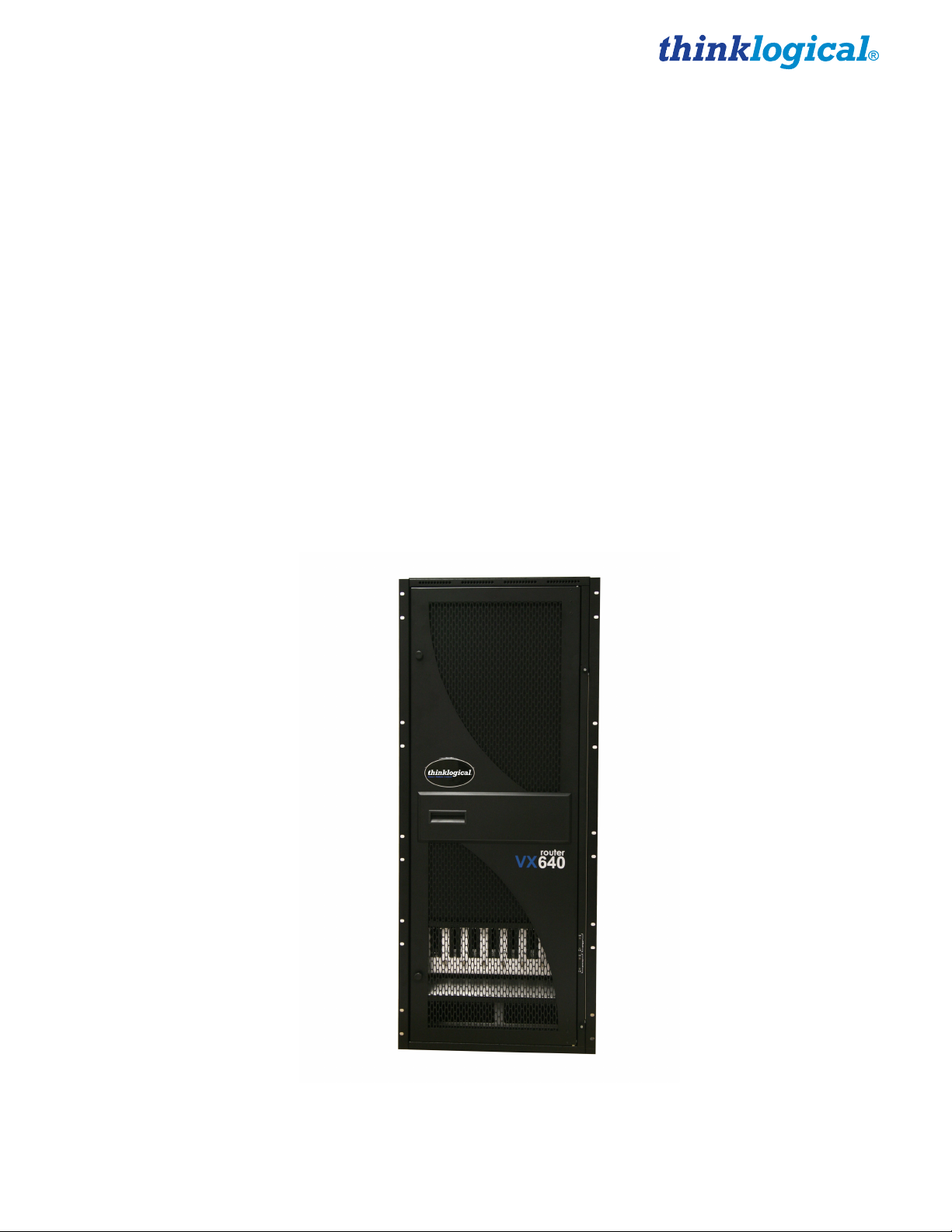
The VX640 is a high performance modular router and non-blocking matrix switch for
complete, end-to-end routing of video and peripheral signals over multi-mode or singlemode fiber optic cable.
This highly reliable and resilient router is expandable from 20x20 up to 640x640, which allows for flexible
deployment configurations. In addition, the VX640 series provides mission critical dependability and
unrivalled signal integrity. Being protocol agnostic, the switch supports DVI, SDI, HD-SDI, Dual-link DVI,
Dual-link SDI, USB HID, USB 2.0 and audio.
Thinklogical’s VX640 Router® includes:
• (2) Redundant, Current Sharing Power Supply Modules for the Upper Cage
• (2) Redundant, Current Sharing Power Supply Modules for the Lower Cage
• (1) Fan Tray Module (includes three fans)
• (1) Primary Controller Card
• (8) Switch Cards
• (1) Interconnect Card
Optional Modules (Spares):
VX640 Router Data Input/Output Card, 20 Ports, SFP+
VX640 Router Fail-Over Controller Card
VX640 Router Switch Card
VX640 Router Fan Tray
VX640 Router Power Module
The VX640 Router is available with LC-type fiber connectors.
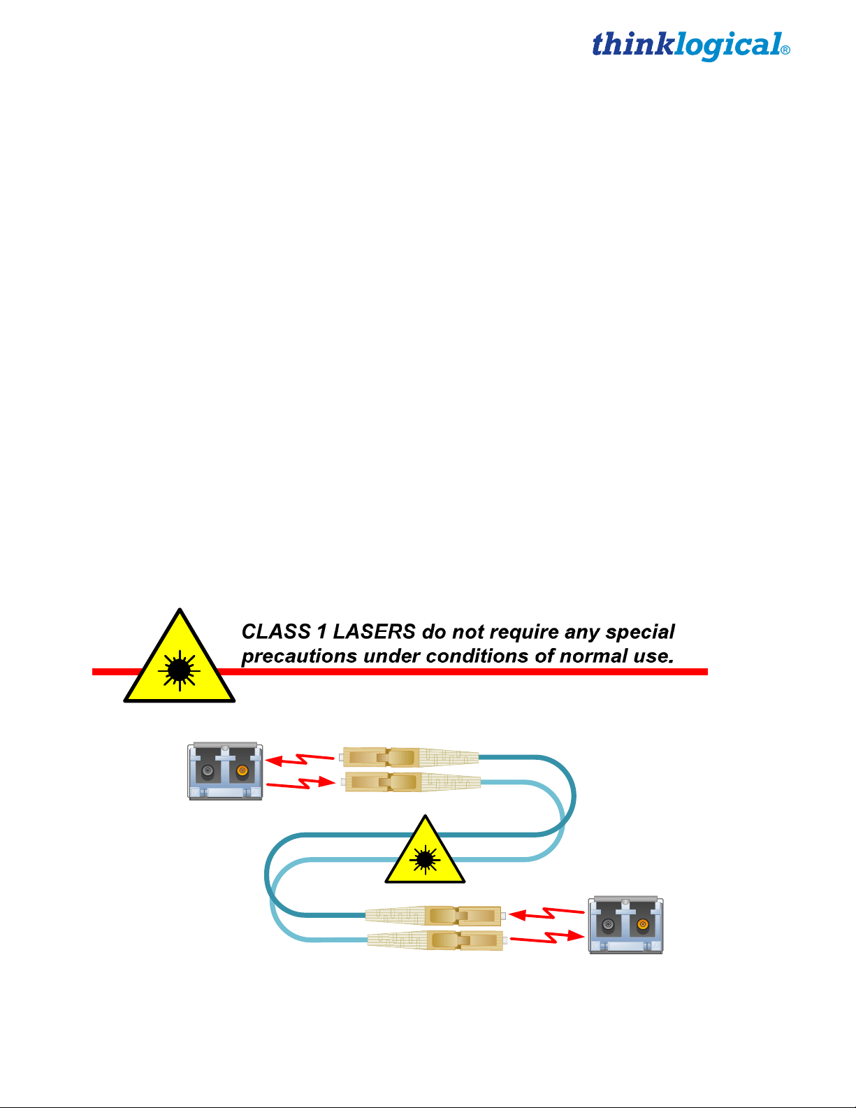
Laser Information
The VX640, like all Thinklogical® products, is designed and identified as a
SFP
Modules
Class 1 Lasers
Class 1 LASER product.
Fiber-Optic
Cables
VX640 Router Manual, Rev. F 1 November, 2013
Page 7
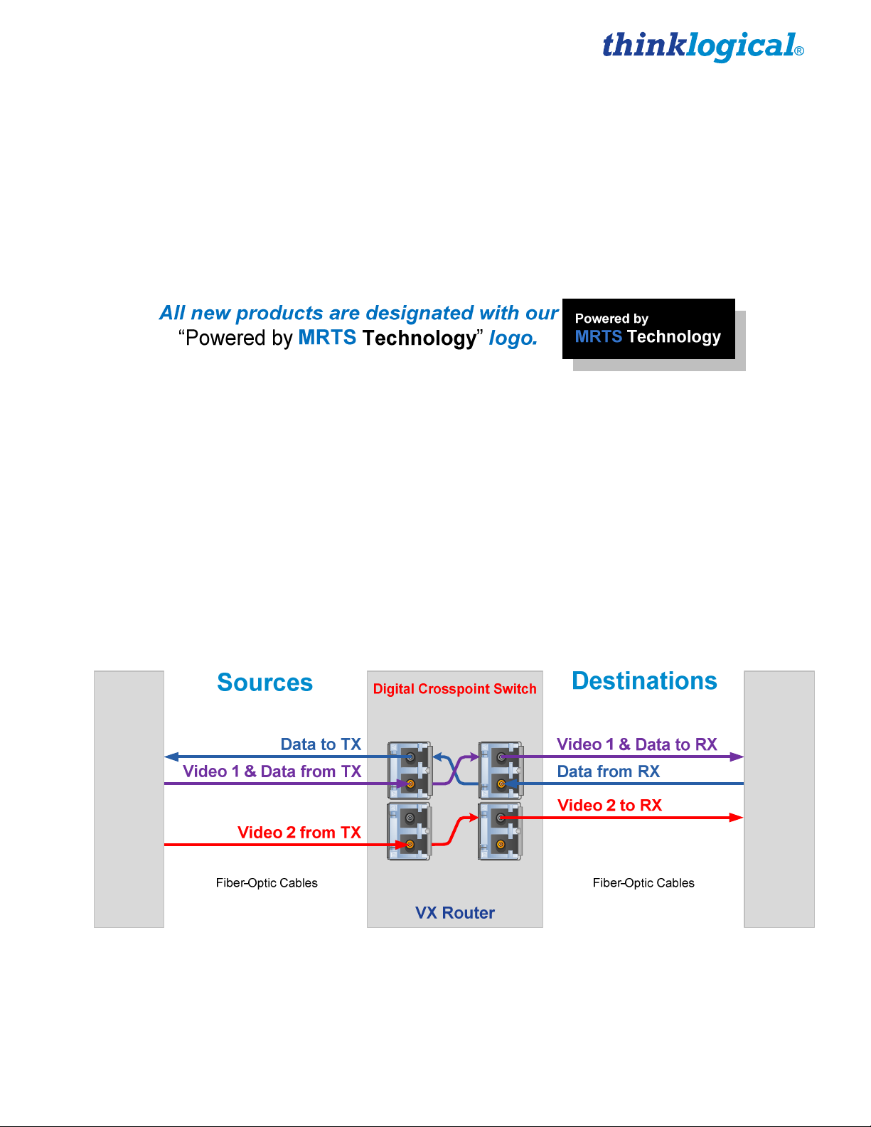
Theory of Operation
MRTS Technology
Thinklogical’s® VX640 KVM Matrix Switch, used together with our Velocity Extenders,
incorporates our breakthrough patent-pending technology for transmission and reception of DVI,
HID, and high-speed data peripherals across long or short distances.
This technology, known as Multi Rate Transmission System (MRTS), provides end-to-end data transmission with unparalleled performance. This unique optic platform enables multiple data streams to be
transmitted long distances over single or multiple fibers with complete reconstruction of the data clock at
the destination end point. The result is perfect synchronization with each transmitted stream.
MRTS is a highly reliable technology and delivers powerful benefits to our customers when combined
with our new SFP+ optics. The new MRTS Technology has the ability to transport every frame of a 1920
x 1200 @ 60Hz (or higher) video stream with no compression, along with all desktop peripherals
(keyboard, mouse, etc., including 480Mbps USB 2.0) with no perceptible latency. Moreover, these
signals can be transmitted distances from just a few meters up to 40 kilometers over single-mode or
multi-mode fibers.
MRTS allows for traditional AV implementations and video routing to be incorporated into the same
switch fabric, providing greater value, flexibility, performance and security. Additional unique capabilities
include the ability to support 6.25Gbps bandwidth per stream, between 50% and 100% higher than our
nearest competitors (typically 1.485Gbps to 3.2Gbps). This is significant because a single DVI stream
requires a 5.4Gbps data rate to accommodate the 165MHz of video data. Our competitor’s lower
bandwidth capability is generally manifested in either dropped frames or lower resolution associated with
compressing schemes. Not so with MRTS Technology.
Velocity Transmitter
Velocity Receiver
MRTS Technology
VX640 Router Manual, Rev. F 2 November, 2013
Page 8
System Features
General System Features
Each VX640 includes the following features:
•
640 Duplex In and Out Fiber Ports for 640 x 640 Non-Blocking Matrix Switching
•
Fiber Optic Non-Blocking Matrix Router
•
Each Video Connection Supports 6.22 Gbps
•
Single-Mode and Multi-Mode Fiber Optic Capability
•
Coaxial SFP Modules for SDI/HD and SDI/3G Video
•
Redundant, Hot-Swappable and Current Sharing Power Supply Modules
•
Hot Swappable, 20 Port Scalability for In and Out Cards
•
Hot Swappable SFP+ Optical Port Connections
•
Hot Swappable Fan Tray with Annunciator Port (for Alarms)
•
Hot Swappable Fail-Over Controller Card (optional)
•
SNMP (2c) Control Protocol
•
Control/Administration X4 Configurator GUI Included
•
Multi-casting and Macros Supported
•
Protocol Agnostic
•
Compatible with all Thinklogical’s® Video and KVM Extension Systems
•
Compatible with all Thinklogical’s® SDI Xtreme 3G+ Extension Systems
.
VX640 Router KVM Matrix Switch
VX640 Router Manual, Rev. F 3 November, 2013
Page 9

Technical Specifications
Dimensions:
Rack Size/Width: EIA 19" (482.6 mm)
Height: 28 RU- 49” (1244.6 mm)
Depth: 16.07” (408.2)
Chassis
Ports 20 x 20 minimum / 640 x 640 maximum
Depth with cable management: 20.36" (517.3 mm)
(Tolerance: ± .039"; .1000 mm)
Weight: 132 lbs (59.87 kg)
Shipping Weight: 160 lbs (72.57 kg)
Power Consumption: 1700 watts fully loaded
Alarm Relay
Contacts
Operating Temp
and Humidity
Power
Requirements
Compliance Approvals for US, Canada, and European Union
Warranty 1 year from date of shipment. Extended warranties available.
Maximum DC: 1A at 30VDC
Maximum AC: 0.3A at 125VAC
Contact resistance maximum: 100 mΩ
0° to 50°C (32° to 122 °F), 5% to 95% RH, non-conde nsing
AC Input: 100-240VAC, 47-63 Hz
Universal AC Power Supply
PART 1: HARDWARE
Contents
When you receive your Thinklogical® VX640 KVM Matrix Switch, you should find the following
items:
• VX640 Chassis (includes 4 Power Modules, Fan Tray, Up to 8 Switch Cards, Upper and Lower
Interconnect Cards and one or two Controller Cards)
• Power Cord – Qty 4 – PWR-000056-R (International connections may differ)
• CAT5 Cable Assembly, 15 Feet – CBL000001-015FR
• Product Manual CD
• Product Quick Start Guide
• Chassis Options (Spares):
• Fail-Over Controller Card – VXM-000025
• Spare Switch Card – VXM-000026
• Spare Fan Tray – VXM-000027
• Spare Power Module – VXM-000028
• Data Input/Output Card, 20 Ports – VXM-DI0R20
If you ordered an EAL/4 certified unit, please verify that you have received the proper materials. The router should
be labeled as (VXR-000640 Rev B). This information is located on a sticker just inside the front door of your router
along with the serial number information. Please also check that you have the correct version of the Velocity Matrix
Router 640 Data Input/Output Cards (MXM-DI0R20 Rev A). This information is located on a sticker on the card with
serial number information
VX640 Router Manual, Rev. F 4 November, 2013
Page 10
The VX640 KVM Matrix Switch ships configured to customer specifications. All physical connections to
the product use industry-standard connectors.
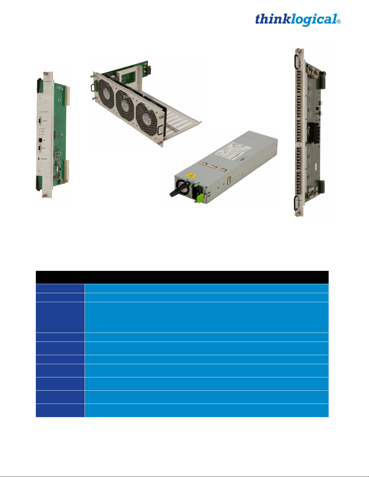
VX640 Modules
Left to right: Controller Card, Fan Tray, AC Power Module, Data Input/Output Card
Ordering Information
Part Number Description
VXR-000640
VXM-DIOR20
VXM-000025
VXM-000026
VXM-000027
VXM-000028
VX640 Chassis
Velocity Matrix Router 640 Chassis
(includes Upper and Lower Cage Backplanes, Upper and Lower Interconnect
Boards, 8 Switch Cards, 1 Fan Tray, 1 Controller Card, and 4 Power Modules)
VX640 Data Card
Velocity Matrix Router 640 Data Input/Output Card, 20 Ports, SFP+, Multi-Mode
VX640 Spares
Velocity Matrix Router 640 Controller Card
Velocity Matrix Router 640 Switch Card
Velocity Matrix Router 640 Fan Tray Module
Velocity Matrix Router 640 Power Module
Thinklogical's VX640 Router
VX640 Router Manual, Rev. F 5 November, 2013
Page 11
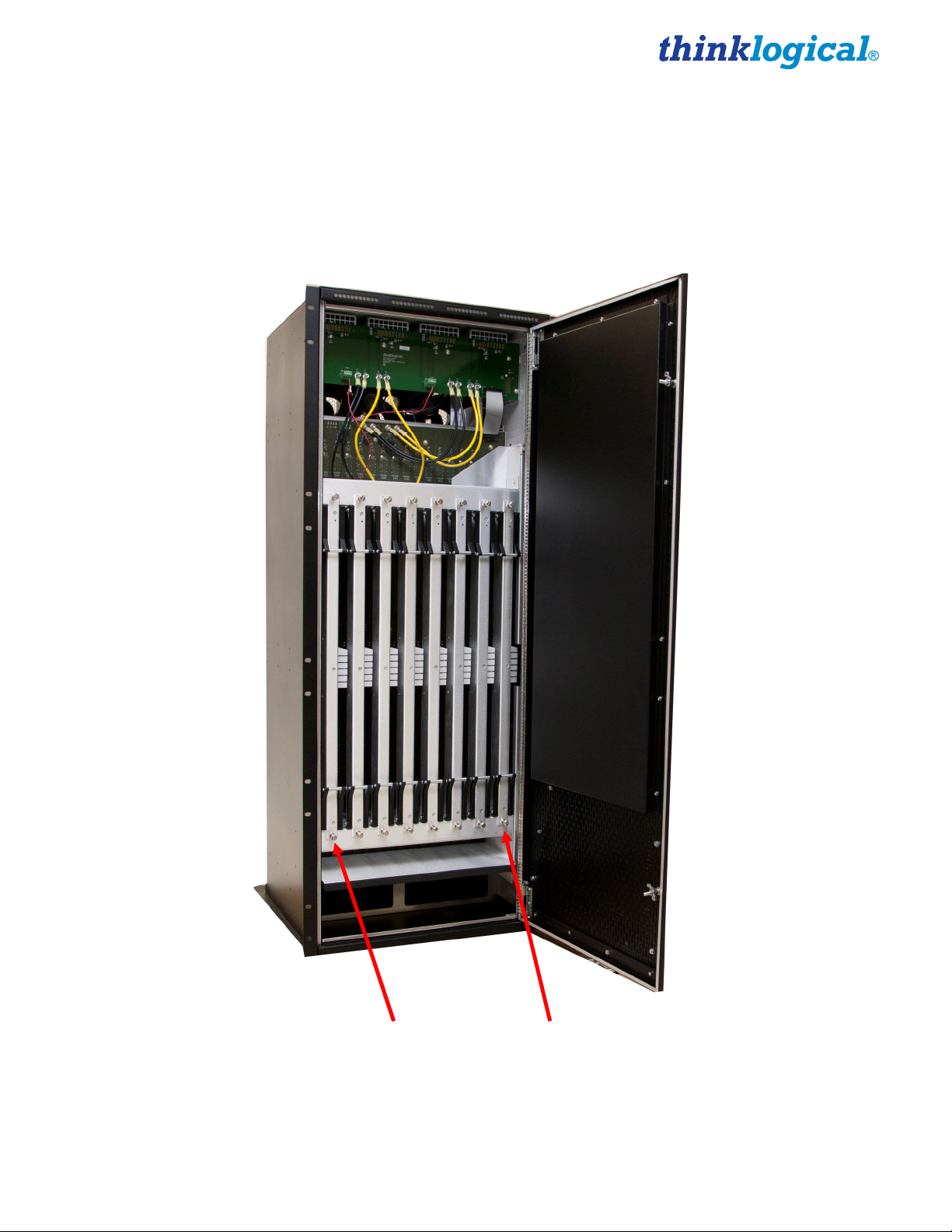
VX640 Modules
Hot-Swappable Modules
The inspired, modular approach of the VX640 means all critical system components, including switch
cards, power supplies, cooling fans and pluggable optics (SFP+), are hot-swappable, thus minimizing
system down-time. (The Interconnect Card is modular, but not hot-swappable. It can be easily replaced
in the field, but the VX640 will need to be shut down.)
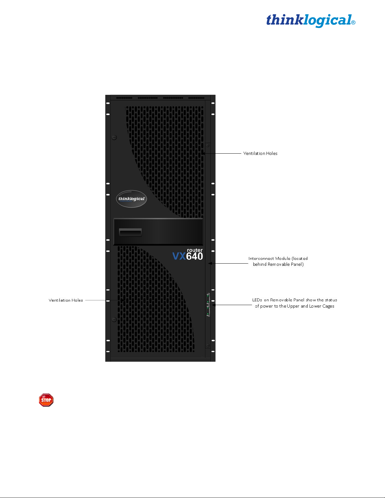
Detailed Front View of VX640
Warning! KEEP THE DOOR CLOSED WHEN IN USE! The VX640 Front Door contains air-
flow baffles that are integral to the router’s cooling system. Do not leave the front door
open or off the chassis for more than a few minutes if the unit is running. Keeping the front
door open for an extended period may lead to a malfunction or damage to the VX640.
VX640 Router Manual, Rev. F 6 November, 2013
Page 12
Interconnect Module
The Interconnect Module connects the Upper Card Cage to the Lower Card Cage. It is located within the
chassis of the VX640. The Interconnect Card contains no active components, but it does have LED
indicators and a DIP Switch for setting the static IP address when connecting to the Ethernet. This
module can be accessed through the front of the router. See the DIP Switch Instructional Guide in
Appendix B, Setting the DIP Switch Instruction Guide (page 30) for detailed instructions on how to
access the Interconnect Module and set the DIP Switch.
The Interconnect Module is NOT hot-swappable.
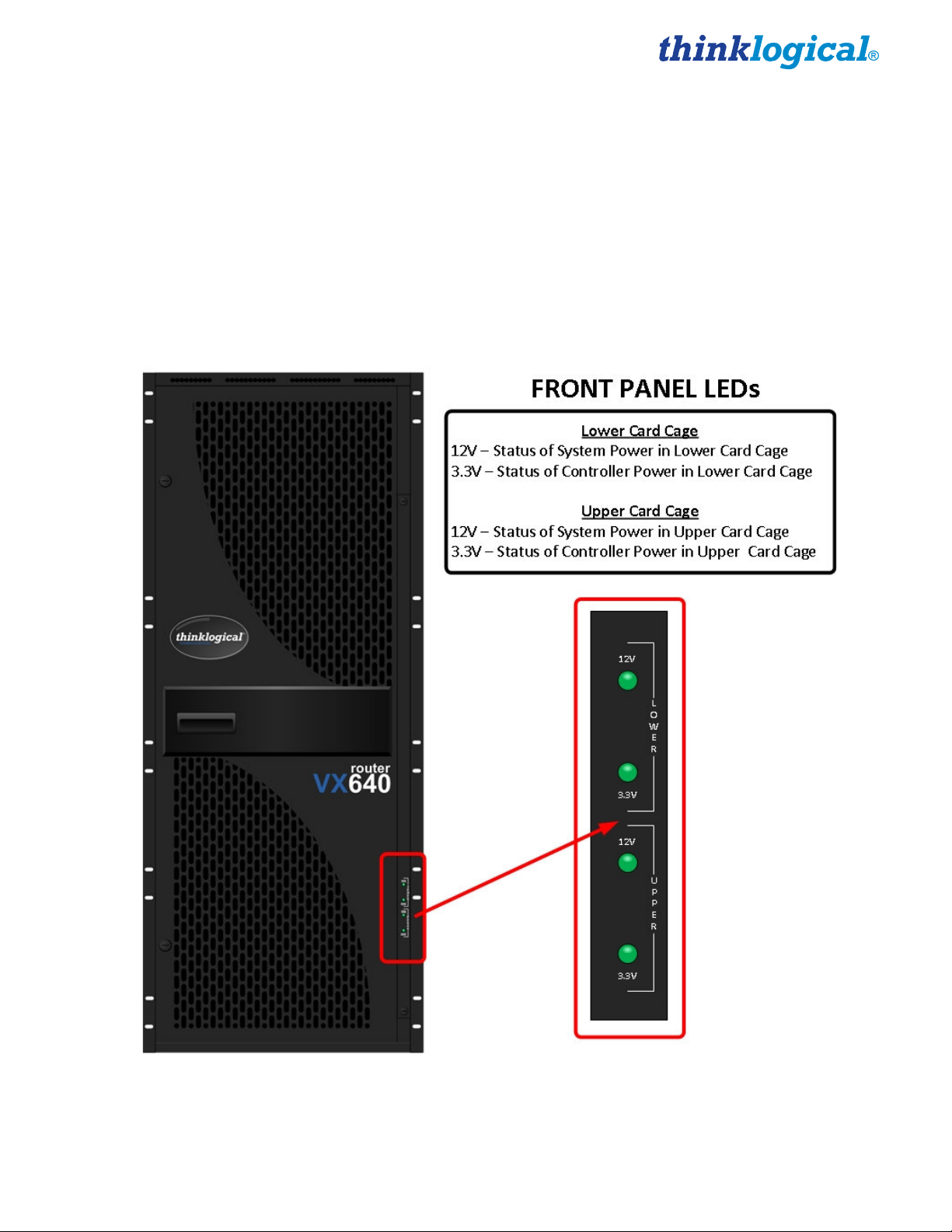
Status LEDs
The VX640 router was designed with status LEDs located on the front of the unit. These LEDs give a
visual indication (LED on) that the System Power (12V) and the Controller Power (3.3V) in both the
Upper and Lower Card Cages is applied.
VX640 Front Panel Status LEDs
VX640 Router Manual, Rev. F 7 November, 2013
Page 13
Switch Card Modules
The VX640 contains 8 Switch Cards which are located behind the Front Door. The Switch cards are
labeled from right (Card 1) to left (Card 8). These cards contain the cross-point fabric of the router,
allowing for 8 possible paths to make connections. In the event that a Switch Card fails, some
connections may not be allowed.
The hot-swappable feature allows for easy replacement of a Switch Card without the need to shut
down the VX Router.
Card 8 Card 1
VX640 Switch Cards
VX640 Router Manual, Rev. F 8 November, 2013
Page 14
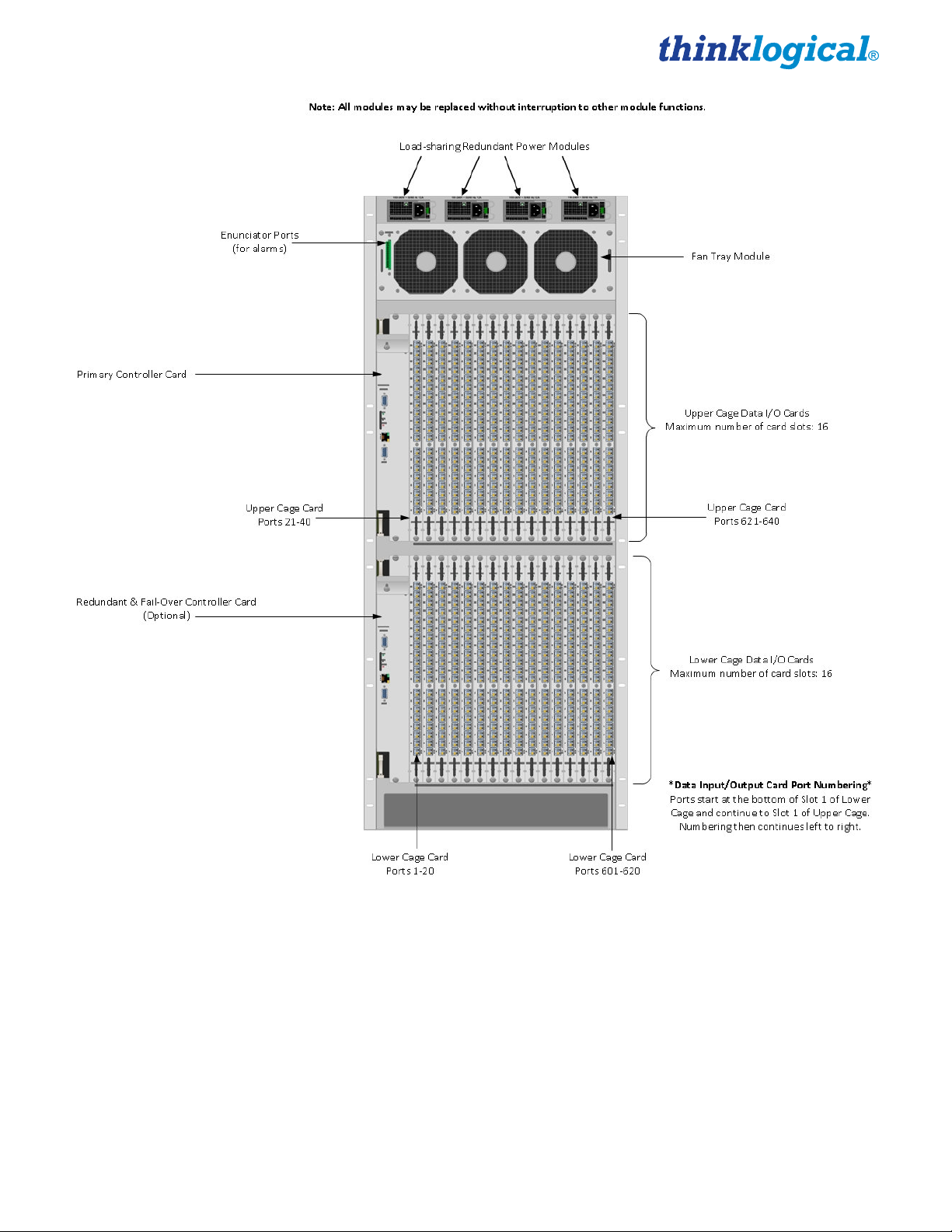
Detailed Rear Panel View of VX640
VX640 Router Manual, Rev. F 9 November, 2013
Page 15

Power Supplies
The dual, redundant power supplies for each card cage ensure continuous, uninterrupted power. The
supplies are current sharing which means the supplies equally share the load. If a power supply fails,
the redundant power supply can support the entire current load of one fully populated card cage.
Although the VX Router functions properly with one Power Module per card cage, it is recommended
that both modules be used, preferably connected to two independent power sources (for redundancy).
Additionally, the hot-swappable feature allows for easy replacement of a module without interrupting the
VX Router’s system functionality. All four power supplies should be turned on during normal use,
even if one of the card cages is not populated with modules.
Fan Tray
The VX640 Router uses 3 DC fans located in one modular, hot-swappable fan tray designed for easy
replacement without interrupting system functionality. The Fan Tray forces air into the chassis
through air baffles in the front door. This cools the vertically mounted I/O cards, the integrated
circuits on the Switch Cards, and the backplane, as well as removing any heat generated by
the power supply modules. (Each power supply module also has its own, internal cooling fan.)
Warning! KEEP THE DOOR CLOSED WHEN IN USE! The VX640 Front Door contains air-
flow baffles that are integral to the router’s cooling system. Do not leave the front door
open or off the chassis for more than a few minutes if the unit is running. Keeping the front
door open for an extended period may lead to a malfunction of the VX640.
The Fan Tray is also equipped with an Annunciator Port for the use of alarms. The system alarms can
be configured to trigger an external control system or generate e-mail notifications.
ALARM
Annunciator
Ports for
ALARMS
VX640 Fan Tray with Alarm Annunciator
The VX640 Critical Hardware Alarms are as follows (Contacts are NC, Normally Closed):
Alarm Descriptions for the VX640
VX640 Router Manual, Rev. F 10 November, 2013
Page 16

Controller Card
The hot-swappable Controller Card connects the Router to an External CPU. The serial port can also be
used for 3rd party controller integration (such as Crestron, AMX or home-spun interfaces). Also, the X4
Configurator Software can be used to control the VX Router via the LAN port.
Ethernet Control
If the VX640 KVM Matrix Switch is to be controlled via Ethernet, it will require a static IP address. This
value can be set via the DIP switch located on the Interconnect module. See Appendix B, Setting the
DIP Switch Instruction Guide (page 30) for detailed instructions on how to access and set the DIP
Switch. Factory default setting will be 192.168.13.15.
VX640 DIP Switch Settings
VX640 Router Manual, Rev. F 11 November, 2013
Page 17

The simplest network connection is an isolated network with only the VX640, the control server, and any
control clients using static IP addresses. The VX640 can be set to any of the above settings. The control
server must be at 192.168.13.9, and the control clients could then be set to any other addresses in the
192.168.13.X family.
If static IP addresses for the control server and its clients are not possible, then the control server will
require two (2) network interfaces with one interface set to the static address 192.168.13.9 and
dedicated to the VX640 KVM Matrix Switch(s) while the other network interface can be configured as
required by the facility's network administrator.
The External Control CPU must meet the following minimum requirements:
•
RedHat EL5.3 installed (or CentOS 5.3) (32-bit, not 64-bit, version)
•
Windows XP, Windows 7
•
Mac OS X
•
1 Gig RAM
•
1 DVD drive
•
VGA and/or DVI video port
•
USB or PS2 Keyboard / Mouse
•
2 network ports (Port 1 - system maintenance, Port 2 – VX640 dedicated
•
80 Gig (minimum) hard drive
•
1 optional RS-232 serial port (Crestron/AMX serial access)
A Back-Up Controller Card is optional to ensure uninterrupted functionality if the Primary Controller
Card fails or needs to be replaced. The Primary Controller Card should always be in the upper
controller slot. The back-up card must have a LAN connection that allows it to communicate with both
the Primary Controller and a server with the IP address 192.168.13.9. Without this interface, the backup controller cannot take control of the router.
Pluggable SFP+ Modules
The SFP+ Optical Module is an 8Gbs Short-Wavelength Transceiver
designed for use in bi-directional Fiber Optic Channel links. The modules
are hot-pluggable and operate on 3.3VDC.
Each Input and Output card contains rows of SFP+ modules that serve as
the fiber-optic couplers for the fiber cables to and from the Thinklogical
transmitter and receiver extenders. Individual cards can be removed for
easy access to the SFP+ modules.
Always use dust caps to protect against dust and damage when a fiber
optic connector is not attached to its coupling device (fiber optic equipment, bulkheads,
etc.). All Thinklogical Routers SFPs are fully populated with dust plugs upon shipment.
Note:
the ferrules of unconnected fiber-optic cables.
VX640 Router Manual, Rev. F 12 November, 2013
It is good practice to immediately install dust plugs in unused SFP modules and on
Page 18

Each VX640 I/O card has 20 SFP+s, each mounted within a grounded metal enclosure. Each SFP+
module is locked into its enclosure with a built-in latch handle that can be opened for removal or locked
for installation.
SFP+ Latch Closed SFP+ Latch Open
The latch handle spans the two LC ports. Arrows printed on the handle indicate which port is an INPUT
( ) and which is an OUTPUT ( ).
Input/Output Cards
The hot-swappable Input/Output (I/O) cards provide excellent in-service expansion capabilities in
convenient sets of 20 ports per card, allowing re-configuration without interrupting signal processing. The
VX640 Router will support up to 32 Input/Output Cards.
Each I/O card consists of one Transmit (T) and one Receive (R) optic per port. I/O Cards are available
with LC-type fiber connectors and can be assembled with Single-mode or Multi-mode optics (SFP+).
Each individual VX640 I/O Card numbers the ports 1 through 20. An LED located on each card indicates
when power is applied to that card.
VX640 Router Manual, Rev. F 13 November, 2013
Page 19

Input/Output Port Numbering on the VX640
POWER
At the bottom of the Lower Cage and at the bottom of the Upper Cage, the port numbers
T
20
19
18
17
16
15
14
13
for each slot are listed (all numbering is bottom to top, left to right.
R
12
11
10
The VX640 Router configuration can have a minimum of one I/O Card (20 x 20) and a
maximum of 32 I/O Cards. Each VX640 I/O card contains 20 ports. When fully
9
configured, the VX640 will contain 16 I/O cards in the Upper Card Cage and 16 I/O cards
in the Lower Card Cage. The 32 I/O cards provide a total of 640 Optical Input/Output
connections described as Ports 1-640.
8
The VX640 switching matrix connects any optical output port (SFP+ T) to any
7
6
5
4
3
2
1
optical input port (SFP+ R).
T
R
I/O BOARD
VX640 Router Manual, Rev. F 14 November, 2013
Page 20

VX640 Transmit/Receive Concept
PART 2: SET-UP AND INSTALLATION
Set-Up
All physical connections to the product use industry-standard connectors. Non-supplied cables that may
be needed are commercially available. All connections are found on the rear of the unit.
Note: Insure that all thumb screws are finger tight so that all the modules are properly
held in the chassis.
Step 1
Carefully remove the VX640 KVM Matrix Switch from its shipping container. Inspect the router to
make certain that no damage occurred during shipment.
Step 2
All of the I/O cards are installed at the factory to meet your specific configuration. Insure that the I/O
cards are properly seated in the unit and that all the SFP modules are sealed with a removable
dust plug. All of the I/O cards are held in place by thumb screw retainers.
VX640 Router Manual, Rev. C 15 March, 2013
Page 21

Step 3
Verify that the four power supplies, located above the fan tray, are secure in the chassis.
Step 4
Verify that the fan tray is fully seated in the chassis and that the thumb screws are secure.
Note: If mounting the chassis in a rack, insure that air flow to the fans and the front door
is not restricted.
Step 5
The temperature in the chassis is monitored by internal temperature sensors in several locations.
Sensors located in the Power Supplies, Fan Trays, on the Controller Card(s), on the I/O Card(s),
and on the Switch Cards monitor continuously for any anomalous conditions.
Note: If any of these sensors detect an over temperature condition, power will be removed
from all sensitive components and the system will shut down.
Step 6
All fan speeds are monitored. Any fan speed that does not meet specification will cause an alarm
condition.
Warning! Do not open or remove the front door for more than a few minutes when the unit
is powered. (The door includes air-flow baffles that are part of the cooling system.) The
Switch Card integrated circuits may overheat when operating without the front door
closed.
Note: All failure conditions send out notifications prior to shut down. For a detailed list of
the alarm functions, see page 10: Alarm Descriptions for the VX640.
Step 7
When the VX Router has been inspected and found to be in suitable condition, the installation
process can begin.
Connecting to the VX640
Fiber Optic Cable
Requirements
Thinklogical® recommends SX+ Laser Enhanced (50µm) fiber for your VX640 KVM Matrix Switch and
Velocity Extension System. Multi-mode fiber can extend up to a maximum of 1000m and Single-mode
fiber can extend distances beyond 1000m.
Handling Fiber Optic Cable
Unlike copper cabling, fiber optic cable requires special handling. A small speck of dust or a
scratch to the ferrule tip (the end of the connector) can attenuate the optical signal, rendering
the cable inoperable.
VX640 Router Manual, Rev. F 16 November, 2013
Page 22

Warning! The ends of the connectors (the ferrule) should never come in contact with any
foreign object, including fingertips. Always install a dust cap immediately on the ferrule of any
unused fiber to protect the tip.
Warning! Minimum bend radius must be no less than 3”. Be careful not to kink or pinch
the fiber when using ties.
3"
Connecting to Thinklogical® VelocityKVM Extenders
The VX640 is designed to work with all Thinklogical® products designed with MRTS technology
(e.g. Velocity Extenders). The VX640 and Velocity Extenders are a new, unique class of cost-effective
matrix switching and KVM extension designed for a variety of high-performance computing
environments. Comprised of a fiber-in, fiber-out matrix switch and fiber-optic KVM Transmitter and
Receiver Extenders, this complete system provides transparent and secure routing, switching and
extension of video and high-speed data peripherals to remote destinations with ease.
Connecting to the Receiver
The Velocity Receiver serves as the Destination (desktops, theaters, conference rooms, editing suites,
control consoles, video walls, etc). Depending on your configuration, your KMASS devices (audio,
keyboard, mouse, etc) are first connected to the Receiver using standard cables. Power can then be
supplied to the unit. The Receiver then connects to the VX640 Receiver ports using fiber (Multi-mode
fiber for distances up to 1000m; Single-mode fiber for distances beyond 1000m).
Connecting to the Transmitter
The Transmitter serves as the Source (computer and video entities). Depending on your configuration,
your local KMASS devices (keyboard, mouse, etc) are first connected. The video sources (e.g.
computers) are then connected followed by any local video devices. Power can then be supplied to the
unit. The Transmitter connects to the VX640 Transmitter ports using fiber (Multi-mode fiber for distances
up to 1000m; Single-mode fiber for distances beyond 1000m).
VX640 Router Manual, Rev. F 17 November, 2013
Page 23

Connecting Thinklogical® VelocityKVM-24 Extenders to the VX640
Connecting to a Control CPU
Note: The Control CPU (Computer) is supplied separately.
The VX640 is controlled via a dedicated external Control CPU. This allows for customization as well as
ease of control and administration. Access is provided via a network connection or serial RS-232.
The network and serial RS-232 connection both use the same low level ASCII API syntax. This
command syntax is defined in the document: Router-ASCII-API.pdf. Each line contains only one
command and must end with a carriage return (CR) and line feed (LF), or just a line feed (LF). The
characters are not echoed.
The serial port is configured for 9600 baud, 1 stop bit, no parity, and no flow control. The network
interface listens on TCP port 17567. It accepts the same commands as the serial interface. You may use
telnet to manually open a connection and control the VXRouter using port 17567.
Third-party controllers will control the router by connecting to either the serial or network port. Using the
network is the only means to take advantage of our automatic fail over facility.
Thinklogical offers a web-based control program called 'X4 Configurator'. This program is described in
greater detail in the document: Manual_X4_Configurator.pdf, available on the Thinklogical web site.
VX640 Router Manual, Rev. F 18 November, 2013
Page 24

ASCII API (RS-232) Settings
•
Baud Rate: 9600
•
Data Bits: 8
•
Parity: none
•
Stop Bits: 1
•
Flow Control: XON/XOFF (Software)
•
DB9 DCE
•
A straight (NOT a null-modem) cable is needed to connect to a PC
Firmware
On Screen Display (OSD) - Firmware Option
The X4 Configurator can be accessed and controlled via an OSD (on-screen display) technology. The
X4 Configurator software can be installed on a designated OOB (out-of-band) PC which users can
access from their workstation. A preconfigured hot-key sequence will deliver the X4 Configurator GUI
straight to the user’s desktop monitor. The user can then select the defined sources and destinations
that they wish to connect. While a user is making the connections, they have exclusive use of the OOB
PC. Once they have completed their connections the OOB PC becomes available for the next user. The
OOB PC that has the X4 Configurator loaded on it has a built in timeout function, therefore the PC
cannot be taken out of service for an extended period of time. The timeouts can be set in increments of
one second. Typical timeouts are in the order of 10 seconds.
Upgrades
See APPENDIX C: FPGA Upgrade Application Installation, page 31 and APPENDIX D: FPGA
Download Application Instructions on page 32.
Firmware upgrades are available through Thinklogical®. For technical assistance, please call us at
1-203-647-8700.
Order of Installation Events
Please refer to the Quick Start Guide included with your products for detailed instructions. The
VX640 Quick Start Guide is also available in Appendix A (page 29).
How to Install/Replace Modules
How to Install or Replace Input/Output Cards
Note: A shutdown is not required prior to installing/replacing Input/Output Cards.
Step 1
Turn the card’s two thumbscrews counterclockwise until they disengage from the chassis. Pull the card
out using both handles.
Warning! Do not pull on the thumbscrews when removing the module – damage may
occur! Use the handles!
Step 2
Place the new module upright so that the POWER LED is on the top. Grasp the module by the
handles. The card should slide freely until it reaches the backplane connector. At this point, use
just enough force to firmly engage the card with the mating connector.
VX640 Router Manual, Rev. F 19 November, 2013
Page 25

Warning! If the module does not slide into the connector, do not force it! Damage may
occur. Remove the card and start over.
Step 3
Once the module is completely seated, hand-tighten the thumbscrews.
Warning! Do not tighten the thumbscrews with a screwdriver.
How to Install or Replace an Interconnect Module
Note: Replacing the Interconnect Module will interrupt service.
To replace the Interconnect Module, the front door and front panel must first be removed. (See
Appendix B, page 30.)
Step 1
Turn both front door latches one quarter turn clockwise (arrow on knob pointing up) to release the door.
Step 2
While holding the door steady with one hand, pull down the upper spring-loaded hinge release and pull
the upper portion of the door outward until the latch clears the mounting hole. The door can now be
removed and set aside.
Warning! KEEP THE DOOR CLOSED WHEN IN USE! The VX640 Front Door contains air-
flow baffles that are integral to the router’s cooling system. Do not leave the front door off
the chassis for an extended length of time if the unit is running. Keeping the front door
open for an extended period of time will lead to a malfunction of the VX640.
Step 3
There are two thumb screws holding the front panel to the chassis. Loosen the thumb screws, remove
the front panel and set it aside.
Step 4
There are two thumbscrews on the Interconnect Module; turn the thumbscrews counterclockwise until
they disengage from the chassis. Pull the Interconnect Module out using both black ejector handles.
Step 5
Place the new module upright so that the four Status LEDs are at the bottom. Grasp the module
by the handles. The card should slide in freely until it reaches the backplane connector. At this
point, use just enough force to firmly engage the card with the mating connector.
Warning! If the module does not slide easily into the connector, do not force it! Damage
may occur. Remove the card and start over.
Step 6
Once the module is completely seated, hand-tighten the thumbscrews.
Warning! Do not tighten the thumbscrews with a screwdriver.
Step 7
Replace the front panel that was removed in Step 3.
VX640 Router Manual, Rev. F 20 November, 2013
Page 26

Step 8
Replace the front door that was removed in Steps 1 and 2.
How to Install or Replace a Switch Card
Note: The Switch Cards are hot-swappable; the VX640 system does not need to be
Step 1
Turn the thumbscrews counterclockwise until they disengage from the chassis. Pull the Switch Card out
using both black ejector handles.
Step 2
Place the new module upright so that the integrated circuitry/components are on the right side of
the card. Grasp the module by the handles or by the outer edge of the aluminum housing. The card
should slide freely until it reaches the backplane connector. At this point, use just enough force to
firmly engage the card with the mating connector.
Step 3
Once the module is completely seated, hand-tighten the thumbscrews.
shutdown to replace.
Warning! If the module does not slide into the connector, do not force it! Damage may
occur. Remove the card and start over.
Warning! Do not tighten the thumbscrews with a screwdriver.
How to Install or Replace a Controller Card
Note: When using a single Controller, the top Controller slot is always Primary.
Note: Replacing the Controller Card will interrupt service if a second (Fail-over
Controller Card) is not installed.
Step 1
Turn the thumbscrews counterclockwise until they disengage from the chassis. Pull the Controller Card
out using both black handles.
Step 2
Place the new module upright so that the ACTIVE LED is on the top. Grasp the module by the
handles or by the outer edge of the aluminum housing. The card should slide freely until it reaches
the backplane connector. At this point, use just enough force to firmly engage the card with the
mating connector.
Warning! If the module does not slide into the connector, do not force it! Damage may
occur. Remove the card and start over.
Step 3
Once the module is completely seated, hand-tighten the thumbscrews.
VX640 Router Manual, Rev. F 21 November, 2013
Page 27

Warning! Do not tighten the thumbscrews with a screwdriver.
How to Replace a Fan Tray
The VX640 uses three DC fans to move air horizontally through the enclosure. Be sure to not block the
air vents on the front and rear of the unit, and leave at least 2” of space on both sides.
Note: Be sure to leave adequate ventilation space on both sides of the units (2” minimum),
especially if units (e.g. Extenders) are being stacked above or below the VX640 KVM
Matrix Switch.
Note: No shutdown is required prior to replacing the Fan Tray.
Step 1
Turn the four thumbscrews counterclockwise until they disengage from the chassis.
Step 2
Pull the Fan Tray module out using both black handles.
Step 3
Place the new module so that the aluminum housing is on the bottom. Hold the new Fan Tray by the
black handles and slide the aluminum housing into the black card guides.
Warning! Do not operate the unit without a Fan Tray installed for more than 10 minutes.
Step 4
Hand-tighten the thumbscrews.
Warning! Do not tighten the thumbscrews with a screwdriver.
How to Replace a Power Supply
Warning! Disconnect the power cord before proceeding!
Note: If only TWO primary power supplies (1 & 3) are installed, shutdown IS required. If
TWO primary power supplies (1 & 3) AND TWO back-up power supplies (2 & 4) are
installed, shutdown IS NOT required.
VX640 Router Manual, Rev. F 22 November, 2013
Page 28

The Power Modules are universal input 120-240VAC 50-60Hz. Use the proper power cord for your
region (supplied with the unit). Although the router functions properly with two Primary Power Modules,
it is recommended that all four Modules (two Primary, two Back-up) be connected to two independent
power sources (for redundancy).
Step 1
Grasp the black handle with one hand.
Step 2
Slide the green tab to the left with the other hand.
Step 3
Pull the Power Module out of the chassis.
Step 4
Insert the new Power Module into the chassis and slide it in until it reaches the backplane connector.
The module should slide freely until it reaches the backplane connector. At this point, use just
enough force to firmly engage the card with the mating connector.
Warning! If the module does not slide easily into the connector, do not force it! Damage
may occur. Remove the module and start over.
PART 3: REGULATORY & SAFETY REQUIREMENTS
Symbols Found on Our Products
Markings and labels on our products follow industry-standard conventions. Regulatory markings found
on our products comply with domestic and many international requirements.
Regulatory Compliance
Thinklogical® products are designed and made in the U.S.A. Our products have been tested by a
certified testing laboratory and found to be compliant with the following standards (both domestic USA
and many international locations):
North America
Safety
ANSI/UL60950-1: 1st Edition (2003)
CAN/CSA C22.2 No. 60950-1-03
LASER Safety
CDRH 21CFR 1040.10
Class 1 LASER Product
Electromagnetic Interference
FCC CFR47, Part 15, Class A
Industry Canada ICES-003 Issue 2, Revision 1
Australia & New Zealand
This is a Class A product. In a domestic environment this product may cause radio interference, in
which case the user may be required to take adequate measures.
VX640 Router Manual, Rev. F 23 November, 2013
Page 29

European Union
Declaration of Conformity
Manufacturer’s Name & Address: Thinklogical®
100 Washington Street
Milford, Connecticut 06460 USA
Telephone 1-203-647-8700
These products comply with the requirements of the Low Voltage Directive 72/23/EEC and the EMC
Directive 89/336/EEC.
Standards with Which Our Products Comply
Safety
CENELEC EN 60950-1, 1st Edition (2001)
LASER Safety
IEC60825:2001 Parts 1 and 2
Class 1 LASER Product
Electromagnetic Emissions
EN55022: 1994 (IEC/CSPIR22: 1993)
EN61000-3-2/A14: 2000
EN61000-3-3: 1994
Electromagnetic Immunity
EN55024: 1998 Information Technology Equipment-Immunity Characteristics
EN61000-4-2: 1995 Electro-Static Discharge Test
EN61000-4-3: 1996 Radiated Immunity Field Test
EN61000-4-4: 1995 Electrical Fast Transient Test
EN61000-4-5: 1995 Power Supply Surge Test
EN61000-4-6: 1996 Conducted Immunity Test
EN61000-4-8: 1993 Magnetic Field Test
EN61000-4-11: 1994 Voltage Dips & Interrupts Test
Supplementary Information
The following statements may be appropriate for certain geographical regions and might not apply to
your location.
This Class A digital apparatus meets all requirements of the Canadian Interference-Causing
Equipment Regulations.
Cet appareil numérique de la classe A respecte toutes les exigencies du Règlement sur le matérial
brouilleur du Canada.
Warning! This is a Class A product. In a domestic environment, this product may cause
radio interference, in which case the user may be required to take corrective measures.
VX640 Router Manual, Rev. F 24 November, 2013
Page 30

Note: This equipment has been tested and found to comply with the limits for a Class A
digital device, pursuant to part 15 of the FCC Rules. These limits are designed to provide
reasonable protection against harmful interference when the equipment is operated in a
commercial environment. This equipment generates, uses and can radiate radio frequency
energy and, if not installed and used in accordance with the instruction manual, may
cause harmful interference to radio communications in which case the user may be
required to take adequate corrective measures at their own expense.
Note: This Class A digital apparatus complies with Canadian ICES-003 and has been
verified as being compliant within the Class A limits of the FCC Radio Frequency Device
Rules (FCC Title 47, Part 15, Subpart B CLASS A), measured to CISPR 22: 1993 limits and
methods of measurement of Radio Disturbance Characteristics of Information Technology
Equipment.
Note:
magnetic fields
Note:
may be needed to comply with Immunity Requirements
The user may notice degraded audio performance in the presence of electro-
.
If using a keyboard that is noise susceptible, a ferrite ring on the keyboard cable
Product Serial Number
Thinklogical® products have a unique serial number, imprinted on an adhesive label that is fixed to the
bottom of the chassis. The serial number includes a date-code. The format for the date-code is 2 digits
for the month, 2 digits for the day and 2 digits for the year, plus two or three digits for a unique unit
number. This serial number is also found on the original shipping carton.
Connection to the Product
Connections and installation hardware for our products use industry-standard devices and methods. All
wiring connections to the customer equipment are designed to minimize proprietary or customized
connectors and cabling. Power connections are made with regionally appropriate power cords and
approved methods.
PART 4: THINKLOGICAL® SUPPORT
Customer Support
Thinklogical® is an engineering company and you will receive any information you require
directly from our most knowledgeable engineers. We believe that the first lines of support are
design engineers that developed each particular product. Therefore, your questions will be
handled promptly by our in-house engineers who are most familiar with your products.
VX640 Router Manual, Rev. F 25 November, 2013
Page 31

Website
Check out our website for firmware updates, support information and general information about all of the
products we offer.
Our website offers product information on all current systems, including technical specification sheets
and installation guides (for viewing online or for download), product diagrams showing physical
connections and other helpful information.
Internet: www.thinklogical.com
Note: Most online documents are stored as Adobe Acrobat “PDF” files. If you do not have
the Adobe Acrobat reader needed to view PDF files, visit www.adobe.com for a download.
FTP Site
In addition to our web site, we also have an .ftp site that contains important documents and files. In
addition to technical documents, it contains ISO files that may be used to burn copies of the CDs we
include with our routers, the X4 Configurator manual and an installable version of X4 for Windows and
Linux.
The ftp site is: ftp.thinklogical.com
These manuals are available on our ftp site for downloading:
•
Router-ASCII-API.pdf
•
Router_Interfaces.pdf
•
Configuring-the-ASCII-Interface.pdf
•
Router_SNMP_Traps.pdf
Router SNMP MIB definition files are also available for downloading:
•
LSI-ROOT.mib
•
LSI-ROUTER-API-INTERFACE.mib
•
LSI-SFP.mib
•
LSI-VXROUTER.mib
Email
Thinklogical® is staffed Monday through Friday from 8:30am to 5:00pm, Eastern Time Zone. We will
try to respond to your email inquiries promptly, use the following email addresses for your different
needs:
info@thinklogical.com – Information on Thinklogical® and our products.
sales@thinklogical.com – Sales Department - orders, questions or issues.
support@thinklogical.com – Product support, technical issues or questions, product
repairs and request for Return Authorization.
VX640 Router Manual, Rev. F 26 November, 2013
Page 32

Telephone
Telephone Sales: Contact our expert sales staff via telephone in Milford, CT at 1-203-647-8700 or if in
the continental US, you may use our toll-free number 1-800-291-3211. We are here Monday through
Friday from 8:30am to 5:00pm, Eastern Time Zone. Ask for your representative’s direct dial phone
number when you call.
Telephone Product Support: Contact Product Support via telephone in Milford, CT at 1-203-647-8700.
The support lines are manned Monday through Friday, 8:30am to 5:00pm, Eastern Time Zone.
International Sales: Please contact our US sales staff in Milford, CT at 1-203-647-8700. We are here
Monday through Friday, 8:30am to 5:00pm, Eastern Time Zone (same as New York City). If leaving a
voice message please provide a “best time to call back” so we may reach you at your convenience.
Our switchboard attendant will direct your call during regular business hours. We have an automated
attendant answering our main telephone switchboard after regular business hours and holidays. You can
leave voice messages for individuals at any time. Our Sales Representatives have direct numbers to
speed up your next call to us.
Fax
Our company facsimile number is 1-203-783-9949. Please indicate the nature of the fax on your cover
sheet and provide return contact information.
Product Support
Thinklogical’s® support personnel are available Monday through Friday from 8:30am to 5:00pm,
Eastern Time Zone. If your application requires assistance at some time outside of our normal business
hours, please contact us beforehand and we will do our best to make arrangements to help you with your
Thinklogical® products.
Warranty
Thinklogical® warrants this product against defects in materials and workmanship for a period of one year
from the date of delivery. Thinklogical
Note: Thinklogical® Inc. products carry a one year warranty, with longer term available at
time of purchase on most products. Please refer to your product invoice for your products
Warranty Terms & Conditions.
Defect remedy shall be the repair or replacement of the product, provided that the defective product is
returned to the authorized dealer within a year from the date of delivery.
If you wish to return your device, contact the Thinklogical® authorized dealer where you purchased the
device, or if you purchased directly, call Thinklogical® at 1-800-291-3211 (USA).
Return Authorization
In the event you must return a product to Thinklogical® directly, please contact Customer Support at
1-800-291-3211 or 1-203-647-8700. Customer Support will ask you to describe the problem and will
issue you a Return Merchandise Authorization number (RMA#). Pack the device in its original box, if
possible, and return it with the RMA# printed on the outside of the box.
and its suppliers disclaim any and all other warranties.
®
Note: DO NOT return a product to Thinklogical® without a Return Material Authorization.
VX640 Router Manual, Rev. F 27 November, 2013
Page 33

Return address for products with Return Material Authorization:
Thinklogical, LLC
®
Attn: RMA#
100 Washington Street
Milford, CT 06460 USA
PH: 1-800-291-3211 (USA only)
Our Address
If you have any issue with a product, have product questions or need technical assistance with your
Thinklogical® system, please call us at 1-800-291-3211 (USA only) or 1-203-647-8700 and let us help.
If you’d like to write us, our mailing address is:
Thinklogical, LLC®
100 Washington Street
Milford, CT 06460 USA
VX640 Router Manual, Rev. F 28 November, 2013
Page 34

APPENDIX A: VX640 QUICK START GUIDE
VX640 Router Manual, Rev. F 29 November, 2013
Page 35

Appendix B: Setting the DIP Switch Instruction
VX640 Router Manual, Rev. F 30 November, 2013
Page 36

Appendix C: FPGA Upgrade Application Installation
VX640 Router Manual, Rev. F 31 November, 2013
Page 37

Appendix D: FPGA Download Application Instructions
VX640 Router Manual, Rev. F 32 November, 2013
Page 38

Appendix E: Secure Applications
VX Router Control
When used in a secure application, the VX Router and External Computer (server) used to manage the
Router must be located in a physically secure environment to which only trusted administrators have
access. Similarly, the server used to manage the VX Router must be physically protected and have
suitable identification/authentication mechanisms to ensure that only trusted administrators have access.
Thinklogical’s VX Router uses two methods for secure routing. One is known as Restricted Switching
and the other is known as Partitioning. These methods can be deployed singularly or jointly, depending
on security requirements.
Restricted Switching
Restricted Switching provides multiple levels of security classification domains on the same VX Router.
Each destination must ensure that no unauthorized content is displayed or accessed, therefore, each
input and output needs to be prioritized. Priorities can range from 1 to the total number of ports in the VX
VX640 Router Manual, Rev. F 33 November, 2013
Page 39

Router. An output can connect to an input with a priority greater than, or equal to, its priority. Thus, a
priority level of 1 on an output can connect to any input (priority 1, 2, 3…).
The user must provide a table defining the priorities for each input and output of the switch matrix. This
table is in the form of a comma separated value (csv) file. This file contains the values in three columns:
Port Direction (i=input, o=output), Port Number and Port Priority. For example:
I/O Number Priority
"i", 1, 1
"i", 2, 2
"i", 3, 3
"i", 4, 1
"i", 5, 3
"o", 1, 1
"o", 2, 3
"o", 3, 2
"o" 4, 4
"o", 5, 1
Output 1 can connect to ports 1-5.
Output 2 can connect to ports 3 and 5.
Output 3 can connect to ports 2, 3, and 5.
Output 4 cannot connect to any ports.
Output 5 can connect to ports 1-5.
Note that Port Direction (i or o) is in quotes and that the table must use only the following ASCII printable
characters:
Double quotes (or speech marks), character code = 34 (")
Lower case i character code = 105 (i)
Lower case o character code = 111 (o)
Comma character code = 44 (,)
Carriage Return character code = 13 (CR)
Line Feed character code = 10 (LF)
The VX Router will interpret the Restricted Switching Table (csv file) during the boot-up. Any errors that
occur during the Restricted Switching Table interpretation process will be logged in the messages file at
the following location: var/log/messages
It is recommended that the Messages File be reviewed and any errors in the Restricted Switching Table
be corrected before implementing multiple levels of security classification domains on the same VX
Router. It is also recommended that Restricted Switching be fully tested before implementing multiple
levels of security classification domains on the same VX Router.
The Restricted Switching Table files for the VX640 Router are stored on the Controller Card at the
following location:
var/local/vxrouter/restrict/upstream.csv
var/local/vxrouter/restrict/downstream.csv
Restricted switching is disabled when Restricted Switching Table files are removed. By default, when
there are no Restricted Switching Table files, all input and output ports will have a priority of 1. All VX
Routers are shipped without Restricted Switching Table files stored on the Controller card and therefore
do not restrict any connection.
VX640 Router Manual, Rev. F 34 November, 2013
Page 40

Restricted Switching with VX Routers
Restricted Switching Priority Scheme
The following example shows a priority scheme for four levels of security managed by one VX Router:
For Video:
Destination workstations in the RED network can see what is transmitted by source computers in the BLACK, GREEN, BLUE & RED networks.
Destination workstations in the BLUE network can see what is transmitted by source computers in the BLACK, GREEN & BLUE networks.
Destination workstations in the GREEN network can see what is transmitted by source computers in the BLACK & GREEN networks.
Destination workstations in the BLACK network can see what is transmitted by source computers in the BLACK network only.
For Keyboard & Mouse:
Destination workstations in the RED network can control source computers in the BLACK, GREEN, BLUE & RED networks.
Destination workstations in the BLUE network can control source computers in the BLACK, GREEN & BLUE networks.
Destination workstations in the GREEN network can control source computers in the BLACK & GREEN networks.
Destination workstations in the BLACK network can control source computers in the BLACK network only.
Restricted switching is configured via firmware loaded into the VX Router. The configuration file for this scenario would look like this
(where the first value is “i” for input or “o” for output, the second value is the port number and the third value is the priority level).
Important Notes:
In this scenario, ports 1-4 in card 1 an ports 6-9 in card 2 are used. However, any ports on any cards can be used.
(Each card has five ports numbered 1-5, bottom to top.)
The number of priority levels that can be managed by one VX Router is the same as the number of ports in the VX Router:
The VX40 and VX80 can support 80 priority levels. The VX160 can support 160 priority levels and a VX320 or VX320Video
can support 320 priority levels.
“i”,1,4
“i”,2,3
“i”,3,2
“i”,4,1
“i”,6,1
“i”,7,2
“i”,8,3
“i”,9,4
“o”,1,1
“o”,2,2
“o”,3,3
“o”,4,4
“o”,6,4
“o”,7,3
“o”,8,2
“o”,9,1
Note: When using a Back-up Controller configuration, both controllers must have the same
Restricted Switching Table file(s).
Partitioning
Partitions allow VX Router sources and destinations to be segregated. Therefore, destination work
stations will only receive signals that are transmitted from source computers in the same partition. In
addition, it is impossible for a source computer to be inadvertently routed outside of its designated
partition as the signals will not be transmitted.
VX640 Router Manual, Rev. F 35 November, 2013
Page 41

Example: VX80 Router with four distinct partitions:
Four partitions set up for secure routing and extension applications. Signals are only capable of
transmitting and receiving within a single partition and not across partitions
The maximum number of partitions is the number of ports that make up the VX Router (80, 160, 320,
640). A VX40 or VX80 Router can be configured with up to 80 partitions, a VX160 up to 160, and so
forth. There are also overlapping partition configurations.
The following example shows a VX80 Router with an overlapping partition:
A VX80 with four partitions: Ports 5-10 are accessible to both partitions 2 and 3.
VX640 Router Manual, Rev. F 36 November, 2013
Page 42

The user must provide a table defining the partitions. This table is in the form of a comma separated
value (CSV) file located in /var/local/router/partition on the VX Router. This file contains the port
number and the partitions to which it belongs. The configuration file for the above scenario looks like
this:
All ports not listed will default to partition 1. Ports can be manually added to partition 1.
Administration Access
There are only two methods by which the administrator can access the VX Router Controller
Configurations:
1. Using the serial console directly connected to the VX Router. (It should be noted that while
no administrator password is required to use the serial console, physical access to the router is
required, therefore the router should be stored in a physically secure location to avoid
unauthorized access.)
2. Using SSH access
The router allows SSH connections to the router for management purposes. SSH sessions are
authenticated using an encrypted password file.
Password Security
For security purposes, the router defaults to using the Message-Digest Algorithm (MD5) and
shadow passwords. It is highly recommended that you do not alter these settings. If you
select the older Data Encryption Standard (DES) format, passwords will be limited to eight
alphanumeric characters (disallowing punctuation and other special characters) with a modest
56-bit level of encryption. The single most important thing you can do to protect the router is
create a strong password.
Creating Strong Passwords:
The password can contain up to 127 characters and cannot contain a space.
MAKE THE PASSWORD AT LEAST EIGHT CHARACTERS LONG. The longer the password,
the more effective it will be. If you are using an MD5 password, it should be approximately 15
characters long. With DES passwords, use the maximum eight character length.
MIX UPPER AND LOWER CASE LETTERS. Passwords are case sensitive, so mixing will
multiply the number of possible combinations.
MIX LETTERS AND NUMBERS. Intersperse numbers within the password to enhance its
strength.
VX640 Router Manual, Rev. F 37 November, 2013
Page 43

INCLUDE NON-ALPHANUMERIC CHARACTERS. Special characters (& $ % >) and
punctuation marks (? “- !) can increase the strength of a password.
Secure Application Examples
The Diagram on page 39 shows the VX640 Matrix Router in a secure application. The highly secure
components are described as the Red Network and the other, lower security components are
described as the Black Network. The Red Network, containing the computers (sources), is shown in a
physically secure environment along with the VX Router, the computer server used to manage the
Router, and the Network Hub. The Network Hub is a dedicated network used only to connect the VX
Router to the computer server. This dedicated network does not connect to any other components and
does not extend beyond the physically secure environment. The dedicated network connection may be
replaced by a direct serial connection (RS-232) between the VX Router and the computer server.
Note: The VX Router and the computer server used to manage the Router must be protected
according to the highest security classification of any component in the entire network
application.
Note: The optical connections and DESTINATION receiver designated as Red Network
must be physically secure.
The VX Router can be configured to prevent accidental connection from the Red Network to the
Black Network using the Restricted Switching feature. For example, the VX640 Matrix Router
Network Diagram should be configured with the following csv file:
I,1,2
I,2,2
O,2,2
I,42,2
O,41,2
O,42,2
I,5,1
O,5,1
I,45,1
O,45,1
The following connection rules will apply:
SOURCE 2 can be connected only to DESTINATION 2.
SOURCE 1 can be connected to both DESTINATION 1 and DESTINATION 2.
VX640 Router Manual, Rev. F 38 November, 2013
Page 44

VX640 Router Manual, Rev. F 39 November, 2013
VX640 Video Secure Application
DVIfrom CPUDVIto Local Display
DVIfrom CPUDVIto Local Display
DVIto DisplayDVIto Display DDC
DVIto DisplayDVI to Display DDC
 Loading...