

Page 1
0
Page 2
®
VX Matrix Switch Manual Rev. Q October 2017
Page 1
Copyright Notice
Copyright © 2017. All rights reserved. Printed in the U.S.A.
Thinklogical, A BELDEN BRAND
100 Washington Street
Milford, Connecticut 06460 U.S.A.
Telephone: 1-203-647-8700
All trademarks and service marks are property of their respective owners.
Subject:
VX40, VX80, VX160, VX320, VX320Video, VX320Audio Matrix Switch Product Manual
Revision:
Q, October 2017
VX40
VX80
VX160
VX320
VX320
Video/Audio
Configurator
®
Website: www.thinklogical.com
Facebook: www.facebook.com/ThinklogicalUSA
LinkedIn: www.linkedin.com/company/thinklogical
Google+: http://plus.google.com/u/0/109273605590791763795/about
YouTube: www.youtube.com/user/thinklogicalNA
Twitter: @thinklogical
Page 3

®
VX Matrix Switch Manual Rev. Q October 2017
Page 2
Table of Contents
PREFACE .................................................................................................................................. 4
About Thinklogical ...................................................................................................................... 4
About this Product Manual .......................................................................................................... 5
Conventions Used in this Manual ............................................................................................... 5
Laser Information ........................................................................................................................ 5
INTRODUCTION ........................................................................................................................ 6
The Logical Solution ................................................................................................................... 6
Theory of Operation .................................................................................................................... 7
MRTS Technology .......................................................................................................... 7
System Features ........................................................................................................................ 8
Technical Specifications ............................................................................................................. 9
VX Matrix Switch Rear Panel Views ......................................................................................... 10
PART 1: HARDWARE ............................................................................................................. 15
Contents ................................................................................................................................... 15
VX Matrix Switch Modules ........................................................................................................ 17
Power Supplies .................................................................................................................. 17
Fan Tray and Alarms ......................................................................................................... 17
The Controller Cards ................................................................................................................ 19
External CPU Controller Cards ..................................................................................... 20
VX Matrix Switch DIP Switch Settings ........................................................................... 20
The Input/Output Cards ............................................................................................................ 21
Micro-HDMI Input/ EDID Output Cards ............................................................................... 21
Pluggable SFP+ Optical Modules .................................................................................. 27
Fiber Optic Cable ...................................................................................................................... 28
Fiber Optic Cable Requirements ................................................................................... 28
Handling Fiber Optic Cable ........................................................................................... 28
Installing Fiber into Input/Output Cards ......................................................................... 29
Removing Fiber from Input/Output Cards ...................................................................... 29
Connecting to Thinklogical Velocity Extenders ......................................................................... 29
Connecting to the Receiver ........................................................................................... 29
Connecting to the Transmitter ....................................................................................... 32
Installation ................................................................................................................................ 35
Set-Up .......................................................................................................................... 35
Order of Installation Events ........................................................................................... 36
How to Replace Modules .......................................................................................................... 36
How to Install or Replace Input/Output Cards ............................................................... 36
How to Install or Replace a Controller Card .................................................................. 37
How to Replace a Fan Tray........................................................................................... 37
How to Replace a Power Supply ................................................................................... 38
PART 2: REGULATORY & SAFETY REQUIREMENTS .......................................................... 38
Symbols Found on Our Products ........................................................................................ 38
Regulatory Compliance ................................................................................................. 38
North America ............................................................................................................... 38
Australia & New Zealand ............................................................................................... 38
European Union ............................................................................................................ 39
Standards with Which Our Products Comply ................................................................. 39
Supplementary Information ....................................................................................................... 39
Product Serial Number ............................................................................................................. 40
Connection to the Product ........................................................................................................ 40
Page 4

®
VX Matrix Switch Manual Rev. Q October 2017
Page 3
PART 3: THINKLOGICAL SUPPORT ...................................................................................... 40
Customer Support .................................................................................................................... 40
Website ......................................................................................................................... 40
Email ............................................................................................................................. 41
Telephone ..................................................................................................................... 41
Fax ................................................................................................................................ 41
Product Support........................................................................................................................ 41
Warranty ....................................................................................................................... 41
Return Authorization ..................................................................................................... 42
Our Addresses .................................................................................................................... 42
APPENDIX A: ORDERING INFORMATION ............................................................................. 43
APPENDIX B: QUICK START GUIDES ................................................................................... 47
APPENDIX C: SD FLASH CARD REPLACEMENT .................................................................. 53
APPENDIX D: SECURE APPLICATIONS ................................................................................ 57
APPENDIX E: TOUCH PANEL CONFIGURATION .................................................................. 68
APPENDIX F: MIB FILE ........................................................................................................... 72
Please note that there is a separate Configurator
(Control Management System with On Screen
Display) Manual available on our website.
MADE IN USA
Configurator
Page 5

®
VX Matrix Switch Manual Rev. Q October 2017
Page 4
PREFACE
About Thinklogical A BELDEN BRAND
We, the Thinklogical team, are committed to understanding and
exceeding our customers’ requirements, the first time and every time.
Thinklogical, a Belden brand, is the leading manufacturer and provider of fiber optic and CATx
KVM, video, audio, and peripheral extension and switching solutions used in video-rich, big-data
computing environments.
Thinklogical offers the only fiber-optic KVM matrix switches in the world that are
accredited to the Common Criteria EAL4, TEMPEST SDIP 24 Level B, and NATO NIAPC
Evaluation Scheme: GREEN and the U.S. DoD DISA JITC UCR 2013 APL information
assurance standards. And Thinklogical Velocity products are the first system with both
KVM and video matrix switching capabilities to be placed on the Unified Capabilities
Approved Product List (UC APL) under the Video Distribution System (VDS) category.
Governments, entertainment, scientific and industrial customers worldwide rely on Thinklogical’s
products and solutions for secure, high performance, continuous operation and ease of
integration. Thinklogical products are designed and manufactured in the USA and are certified to
the ISO 9001:2008 standard.
Thinklogical is headquartered in Milford, Connecticut and is owned by Belden, Inc., St. Louis, MO
(http://www.belden.com). For more information about Thinklogical products and services, please
visit www.thinklogical.com.
Follow Thinklogical on LinkedIn at http://www.linkedin.com/company/thinklogical,
on Facebook at http://www.facebook.com/ThinklogicalUSA,
and on Twitter at https://twitter.com/thinklogical.
Page 6
®
VX Matrix Switch Manual Rev. Q October 2017
Page 5
About this Product Manual
This product manual is divided into three sections: Hardware, Safety Requirements and Product Support.
These are sub-divided to help you find the topics and procedures you are looking for. This manual also
contains Appendices.
Part 1 – Hardware: Pg. 15-This section of the manual contains information and instructions on how to
assemble and use your equipment.
Part 2 – Safety Requirements: Pg. 38-Thinklogical® strongly recommends that you read this section of
the manual prior to starting the hardware assembly.
Part 3 – Product Support: Pg. 40-Thinklogical provides the best customer support available. If you
have any questions or need to contact us, please refer to this section of the manual.
Appendices A-F: Pgs. 43-72
Note and Warning Symbols
Throughout this manual you will notice certain symbols that bring your attention to important information.
These are Notes and Warnings. Examples are shown below.
Note: Important Notes appear in blue text preceded by a yellow exclamation point symbol, as
shown here.
A note is meant to call the reader’s attention to helpful information at a point in the text that is relevant to the
subject being discussed.
Warning! All Warnings appear in red text, followed by blue text, and preceded by a red stop
sign, as shown here.
A warning is meant to call the reader’s attention to critical information at a point in the text that is relevant to the
subject being discussed.
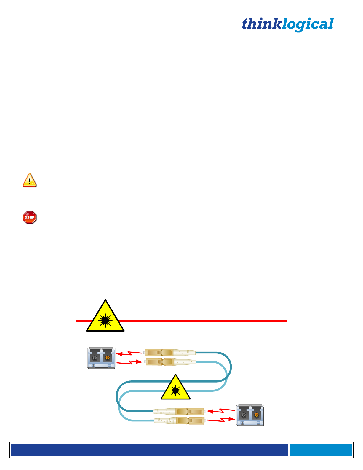
Laser Information
VX Matrix Switches, like all Thinklogical products, are designed and identified as
Class 1 LASER
products.
This means the maximum permissible exposure (MPE) cannot be exceeded when
viewing the laser with the naked eye or with the aid of typical magnifying optics (e.g. telescope or
microscope).
CLASS 1 LASERS do not require any special
precautions under conditions of normal use.
SFP
Modules
Fiber-Optic
Cables
Class 1 Lasers
Page 7

®
VX Matrix Switch Manual Rev. Q October 2017
Page 6
Introduction
The Logical Solution
Thinklogical’s VX40, VX80, VX160, VX320 and VX320Video & Audio Matrix Switches® are high
performance, modular non-blocking matrix switches for complete, end-to-end routing of video and
peripheral signals over multi-mode or single-mode fiber optic cable.
These highly reliable and resilient Matrix Switches provide bidirectional matrix switching and are expandable
from 5x5 to 320x320 Duplex ports, allowing for flexible deployment configurations. The VX40, VX80, VX160,
VX320, and VX320Video/Audio Matrix Switches are available with LC-type fiber connectors.
Thinklogical’s VX Matrix Switches include:
• Redundant, Current Sharing Power Supply Modules (with AC power cords)
• Redundant Controller Cards
• Single Fan Tray (includes three fans)
Optional Modules (Spares):
VX40 Matrix Switch Data Upstream Card, 5 Ports, SFP+
VX40 Matrix Switch Data Downstream Card, 5 Ports, SFP+
VX40 Matrix Switch Redundant Controller Card
VX40 Matrix Switch Power Module
VX40 Matrix Switch Fan Tray
VX80 Matrix Switch Data Input/Output Card, 5 Ports, SFP+
VX80 Matrix Switch Data Downstream Card, 5 Ports, SFP+
VX80 Matrix Switch Redundant Controller Card
VX80 Matrix Switch Power Module
VX80 Matrix Switch Fan Tray
VX160 Matrix Switch Data Upstream Card, 20 Ports, SFP+
VX160 Matrix Switch Data Downstream Card, 20 Ports, SFP+
VX160 Matrix Switch Redundant Controller Card
VX160 Matrix Switch Power Module
VX160 Matrix Switch Fan Tray
(For VX320 and VX320 Video/Audio)
VX320 Matrix Switch Data I/O Card, 16 Ports, SFP+
VX320 Matrix Switch Data I/O Card, 16 Ports, Micro-HDMI (VX320 Video only, w/TLX Control Card)
VX320 Matrix Switch Redundant Controller Card
VX320 Matrix Switch Controller Card with OSD
VX320 Matrix Switch Power Module
VX320 Matrix Switch Fan Tray
See Appendix A on pg. 43 for ordering information on all the Thinklogical VX Matrix Switches.
Also see our Configurator Control Management System Manual (available on our website) for administrative
set-up and control features and OSD (On Screen Display).
Each Thinklogical® Matrix Switch is NATO, Common Criteria EAL/4 and TEMPEST certified.
Page 8
®
VX Matrix Switch Manual Rev. Q October 2017
Page 7
Theory of Operation
MRTS Technology
Thinklogical VX Matrix Switches are used together as a system with our Thinklogical Velocity Extenders
utilizing breakthrough, patent-pending technology for transmission and reception of DVI, keyboard, mouse, and
high-speed data peripherals. This technology, known as Multi Rate Transmission System (MRTS), provides
end-to-end data transmission with unparalleled performance.
This new, unique optic platform enables multiple data streams to be transmitted long distances over
single or multiple fibers with complete reconstruction of the data clock at the destination end point.
The result is perfect synchronization with each transmitted stream.
Powered by
MRTS Technology
All VX products are designated with our
“Powered by MRTS Technology” logo
.
MRTS is a highly reliable technology and delivers powerful benefits to our customers when combined with our
new SFP+ optics. The new MRTS Technology can transport every frame of a 1920 x 1200 @ 60Hz (or higher)
video stream with no compression, along with all desktop peripherals (keyboard, mouse, etc., including
480Mbps USB 2.0) with no latency. Moreover, these signals can be transmitted distances from just a few
meters over multi-mode fibers or up to 40 kilometers over single-mode fibers.
MRTS allows the incorporation of traditional AV implementations and video routing into the same switch fabric,
providing greater value, flexibility, performance and security. Additional unique capabilities include the ability to
support 6.25Gbps bandwidth per stream, between 50% and 100% higher than our traditional systems (typically
1.485Gbps to 3.2Gbps). This is significant because a single DVI stream requires a 5.4Gbps data rate to
accommodate the 165MHz of video data. Traditional technology’s lower bandwidth capability is generally
manifested in either dropped frames or lower resolution associated with compressing schemes. Not so with
MRTS Technology.
Data to TX
Digital Crosspoint Switch
Data from RXVideo 1 & Data from TX
Video 1 & Data to RX
Video 2 to RX
Video 2 from TX
Velocity Transmitter
Velocity Receiver
Fiber-Optic Cables Fiber-Optic Cables
VX Router
Sources
Destinations
MRTS Technology
VX Matrix Switch
Page 9

®
VX Matrix Switch Manual Rev. Q October 2017
Page 8
System Features
System Features
VX40/VX80
VX160
VX320
VX320
Video/Audio
Matrix Size
80x80
320 Duplex
640 Duplex
320x320
Matrix Size Non-Blocking
80x80 Duplex
Non-Blocking
OR 40x40
Duplex Bi-
Directional
Non-Blocking
160x160 Duplex
Bi-Directional
Non-Blocking
320x320
Duplex Bi-
Directional
Non-Blocking
320x320
Duplex Non-
Blocking
Scalability
5 Ports
20 Ports (40 min)
16 Ports
16 Ports
Compatible with Velocity
KVM and Video Extenders
from Thinklogical®
✓ ✓ ✓
✓
Each Video Connection
Supports 6.25 Gbps
✓ ✓ ✓
✓
Single Mode and Multi Mode
✓ ✓ ✓
✓
Redundant, Hot-Swappable
and Current Sharing Power
Supply Modules
✓ ✓ ✓
✓
Hot Swappable SFP+
Optical Modules
✓ ✓ ✓
✓
Hot Swappable Fan Tray with
Annunciator Port (for alarms)
✓ ✓ ✓
✓
Hot Swappable Redundant
Controller Card (optional)
✓ ✓ ✓
✓
Controllable via LAN or
Serial Connection
✓ ✓ ✓
✓
SNMP (2C) Control Protocol
✓ ✓ ✓
✓
Configurator
Software Included
✓ ✓ ✓
✓
Supports
Multicasting and Macros
✓ ✓ ✓
✓
VX Matrix Switch System Features
Page 10

®
VX Matrix Switch Manual Rev. Q October 2017
Page 9
Technical Specifications
VX Matrix Switches, all models:
Humidity 5-95% RH, non-condensing
Operating Temperature 0-50° C (32-122° F)
Alarm Relay contacts Maximum DC: 1A at 30VDC
Maximum AC: 0.3A at 125VAC
Contact resistance maximum: .1Ω
Power Requirements AC Input: 100-240VAC, 47-63 Hz
Universal AC Power
Supply
Technical
Specifications
VX40/VX80
VX160
VX320
VX320
Video/Audio*
Rack Size
Dimensions
EIA 19” (48.26 cm)
EIA 19” (48.26 cm)
EIA 19” (48.26 cm)
EIA 19” (48.26 cm)
Physical
Dimensions- Height
6 RU 10.50”
(26.70 cm)
16 RU 28.0”
(71.12 cm)
24 RU 42.0”
(106.60 cm)
13 RU 22.75”
(57.8 cm)
Physical
Dimensions- Width
17.16” (43.59 cm)
17.19” (43.7 cm)
17.19” (43.7 cm)
17.19” (43.7 cm)
Physical
Dimensions- Depth
15.32”
(16.57” including
card pulls; 42.09
cm)
Depth: 15.0”
(15.75” including
card pulls; 40 cm)
Depth: 15.32”
(15.61” including
card pulls; 39.64 cm;
w/cable
management: 18.36”
including card pulls;
46.64 cm)
Depth: 14.2”
(15.32" including
card pulls; 38.9 cm)
Power Consumption
Approximately 400
Watts Fully Loaded
Approximately 850
Watts Fully Loaded
Approximately 1700
Watts Fully Loaded
Approximately 800
Watts Fully Loaded
Actual Weight
37.1 lbs. (16.83 kg)
103.5 lbs. (46.87 kg)
132.0 lbs. (59.87 kg)
78 lbs. (35.38 kg)
Shipping Weight
100 lbs. (45.36 kg)
152 lbs. (68.95 kg)
160 lbs. (72.57 kg)
100 lbs. (45.36 kg)
*The VX320 Video Matrix Switch uses OSA 40 (6.25G optics) and the VX320 Audio Matrix Switch uses OSA
45 (4G optics)
VX Matrix Switch Technical Specifications
BEFORE STARTING ANY PROCEDURE, IT IS RECOMMENDED
THAT YOU READ THE INSTRUCTIONS THOROUGHLY!
Page 11
®
VX Matrix Switch Manual Rev. Q October 2017
Page 10
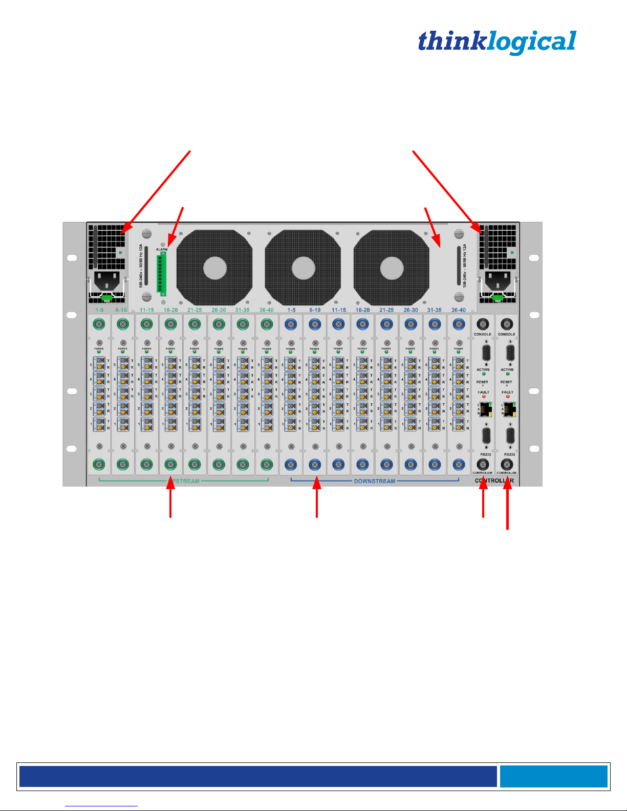
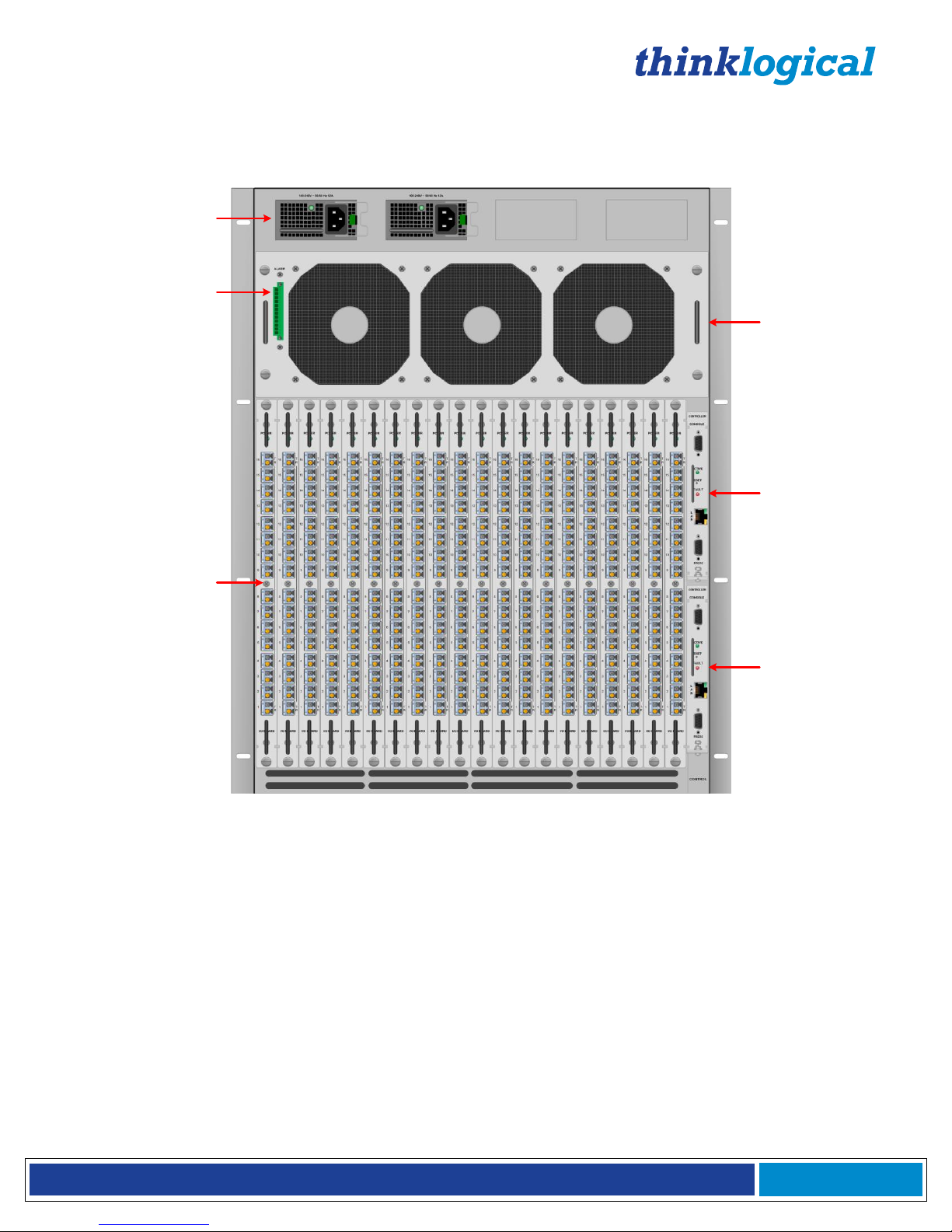
VX Matrix Switch Rear Panel Views
NOTE: All modules may be replaced without interruption to other module functions
(except for the Primary Controller Card)
Load-sharing Redundant Power Supplies
Enunciator Ports (for alarms)
Fan Tray Module
Primary Controller Card
(Back-Up Controller Card is optional)
I/O (Downstream) Cards
Ports 1-40
I/O (Upstream) Cards
Ports 1-40
VX40 Matrix Switch – Rear View
Page 12
®
VX Matrix Switch Manual Rev. Q October 2017
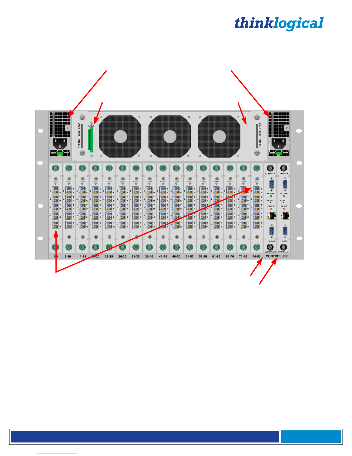
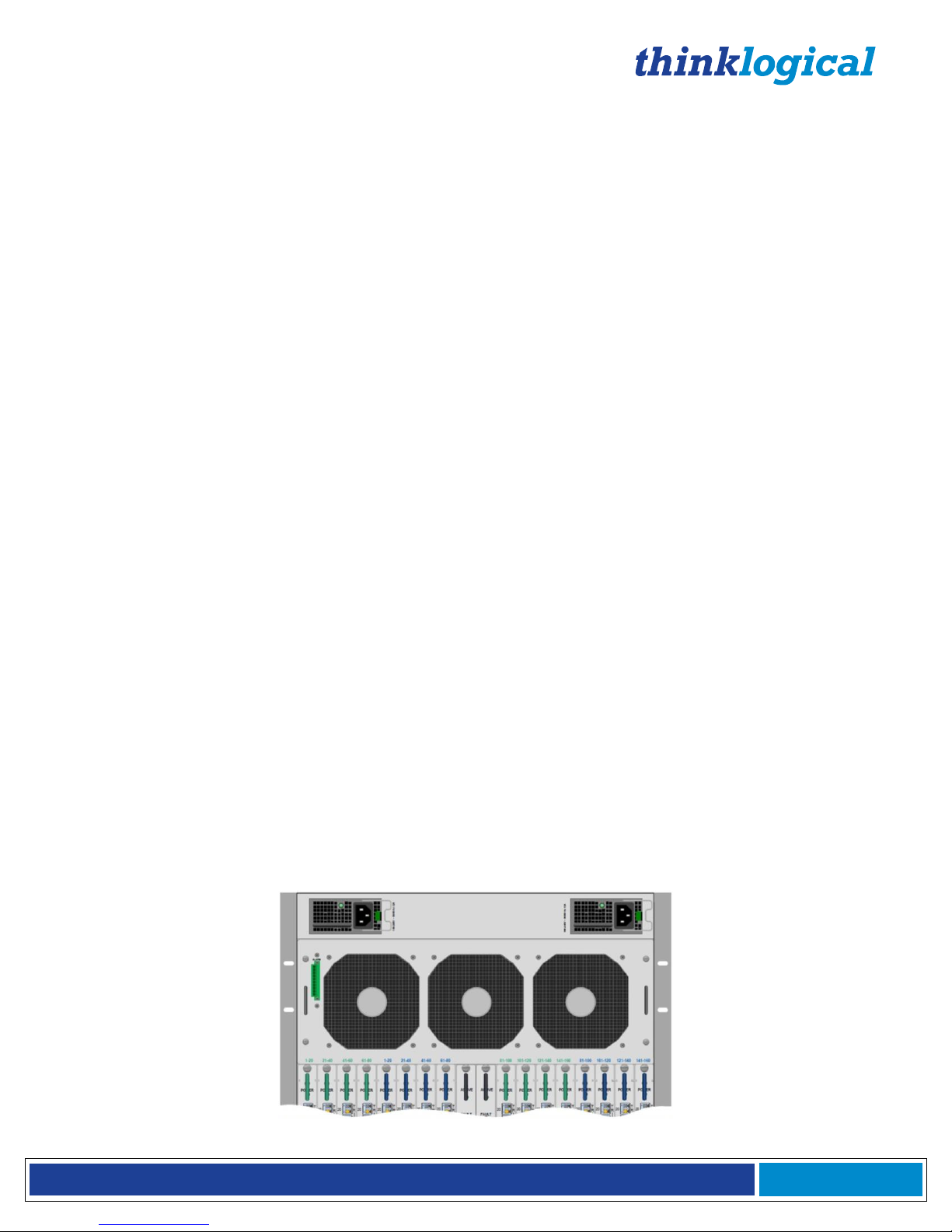
Page 11
NOTE: All modules may be replaced without interruption to other module functions
(except for the Primary Controller Card)
Load-sharing Redundant Power Supplies
Enunciator Ports (for alarms)
Fan Tray Module
Primary Controller Card
(Back-Up Controller Card is optional)
I/O Cards
(Ports 1-80)
VX80 Matrix Switch – Rear View
Page 13
®
VX Matrix Switch Manual Rev. Q October 2017
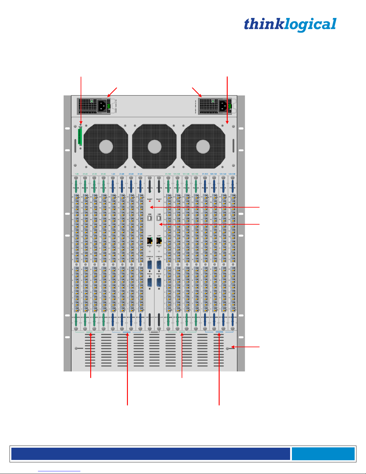
Page 12
Load-sharing Redundant Power
Modules
Enunciator Ports (for alarms)
Fan Tray Module
NOTE: All modules may be replaced without interruption to other modules functions
(except for the Primary Controller Card)
Primary
Controller Card
Optional Back-up
Controller Card
Sliding
thumbscrews
for ventilation
adjustment
I/O (Upstream) Cards
Ports 1-80
I/O (Upstream) Cards
Ports 81-160
I/O (Downstream) Cards
Ports 1-80
I/O (Downstream) Cards
Ports 81-160
VX160 Matrix Switch – Rear View
Page 14
®
VX Matrix Switch Manual Rev. Q October 2017
Page 13
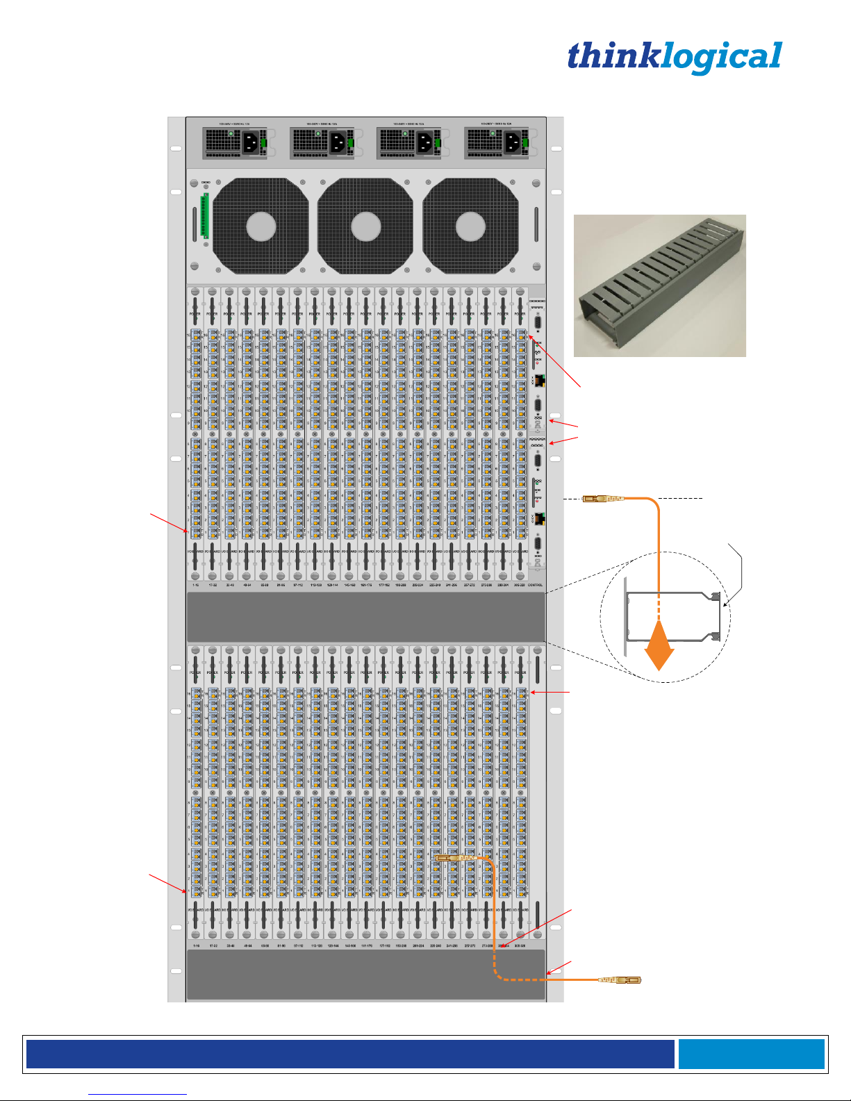
VX320 Router
Back Panel
Cable Caddy (2 places):
4.10" Deep x 2.17" High x 16.0" Wide
(104.14mm x 55.12mm x 406.4mm)
1 2 3 4
Redundant Power supplies, Left to Right:
1 Upper Card Cage Primary
2 Upper Card Cage Back-up
3 Lower Card Cage Primary
4 Lower Card Cage Back-up
1700 Watts
VX320 Router KVM Matrix Switch Chassis: 24 Rack Units
42" High x 17.2" Wide x 14" Deep
(1066.8mm x 436.88mm x 355.6mm)
Cable Caddy 1
Cable Caddy 2
Snap-ON/Snap-OFF Cover
Primary Controller Card
Back-up Controller Card
Upper Card Cage
Lower Card Cage
Fan Tray
Cable Caddy
Upper Card Cage Port 320
Lower Card
Cage Port 320
Lower Card
Cage Port 1
Upper Card
Cage Port 1
Fibers enter
through top of
Caddy...
...emerge from
side of Caddy.
VX320 Matrix Switch – Rear View
Page 15
®
VX Matrix Switch Manual Rev. Q October 2017
Page 14
Power
Supplies
Primary
Controller Card
Input/Output
Cards (1-20)
Enunciator Ports
(for alarms)
Secondary
Controller Card
Fan Tray
VX320VIDEO/AUDIO Router
NOTE: All modules may be replaced without interruption to other module functions
(except for the Primary Controller Card)
VX320VIDEO & VX320AUDIO Matrix Switch – Rear View
VX320VIDEO / VX320AUDIO Matrix Switch
Page 16

®
VX Matrix Switch Manual Rev. Q October 2017
Page 15
Part 1: Hardware
Contents
When you receive your Thinklogical VX40 Matrix Switch, you should find the following items:
• VX40 Chassis (includes 2 Power Modules, 1 Fan Tray Unit, and 1 Controller Card)
• Power Cords – (2) PWR-000006-R (International connections may differ)
• CAT5 Cable Assembly, 15 Feet – CBL000001-015FR
• Product Manual CD
• Product Quick Start Guide
• Chassis Options:
• Redundant Controller Card – VXM-000005
• Spare Fan Tray – VXM-000006
• Spare Power Module(s) – VXM-000007
• Data Upstream Card, 5 Ports – VXM-DI0005
• Data Downstream Card, 5 Ports – VXM-DO0005
The VX40 ships configured to customer specifications. All physical connections to the product use industrystandard connectors.
If you ordered an EAL/4 certified unit, please verify that you have received the proper materials. The Matrix Switch should
be labeled as VXR-000040, Rev B. This information is located on a sticker just inside the front door of your Matrix Switch
along with the serial number information. Please also check that you have the correct version of the Velocity Matrix Switch
40 Data Upstream Cards (VXM-DI0005 Rev A) and Velocity Matrix Switch 40 Data Downstream Cards (VXM-DO0005,
Rev A). This information is located on a sticker on the card with serial number information.
When you receive your Thinklogical VX80 Matrix Switch, you should find the following items:
• VX80 Chassis (includes 2 Power Modules, 1 Fan Tray Unit, and 1 Controller Card)
• Power Cords – (2) PWR-000006-R (International connections may differ)
• CAT5 Cable Assembly, 15 Feet – CBL000001-015FR
• Product Manual CD
• Product Quick Start Guide
• Chassis Options:
• Redundant Controller Card – VXM-000036
• Spare Fan Tray – VXM-000006
• Spare Power Module(s) – VXM-000007
• Data Input/Output Card, 5 Ports – VXM-D00005
The VX80 ships configured to customer specifications. All physical connections to the product use industrystandard connectors.
If you ordered an EAL/4 certified unit, please verify that you have received the proper materials. The Matrix Switch should
be labeled as VXR-000080, Rev B. This information is located on a sticker just inside the front door of your Matrix Switch
along with the serial number information. Please also check that you have the correct version of the Velocity Matrix Switch
80 Data Cards (VXM-D00005, Rev A). This information is located on a sticker on the card with serial number information.
When you receive your Thinklogical VX160 Matrix Switch, you should find the following items:
• VX160 Chassis (includes 2 Power Modules, 1 Fan Tray Unit, and 1 Controller Card)
• Power Cords – (2) PWR-000056-R (International connections may differ)
• CAT5 Cable Assembly, 15 Feet – CBL000001-015FR
• Product Manual CD
• Product Quick Start Guide
• Chassis Options:
• Fail-Over Controller Card – VXM-000001
• Spare Fan Tray – VXM-000002
• Spare Power Module(s) – VXM-000003
• Data Upstream Card, 20 Ports – VXM-DI0020
• Data Downstream Card, 20 Ports – VXM-DO0020
Page 17

®
VX Matrix Switch Manual Rev. Q October 2017
Page 16
The VX160 ships configured to customer specifications. All physical connections to the product use industrystandard connectors.
If you ordered an EAL/4 certified unit, please verify that you have received the proper materials. The Matrix Switch should
be labeled as VXR-000160, Rev B. This information is located on a sticker just inside the front door of your Matrix Switch
along with the serial number information. Please also check that you have the correct version of the Velocity Matrix Switch
160 Data Upstream Cards (VXM-DI0020, Rev B) and Velocity Matrix Switch 160 Data Downstream Cards (VXM-DO0020,
Rev B). This information is located on a sticker on the card with serial number information.
When you receive your Thinklogical VX320 Matrix Switch, you should find the following items:
• VX 320 Chassis (includes 4 Power Modules, 1 Fan Tray Unit, and 1 Controller Card)
• Power Cords – (4) PWR-000056-R (International connections may differ)
• CAT5 Cable Assembly, 15 Feet – CBL000001-015FR
• Product Manual CD
• Product Quick Start Guide
• Chassis Options:
• Fail-Over Controller Card – VXM-000008
• Fail-Over Controller Card with OSD – VXM-000031*
• Spare Fan Tray – VXM-000009
• Spare Power Module(s) – VXM-000010
• Data Input/Output Card, 16 Ports – VXM-D00016
The VX320 Matrix Switch ships configured to customer specifications. All physical connections to the product
use industry-standard connectors.
If you ordered an EAL/4 certified unit, please verify that you have received the proper materials. The Matrix Switch should
be labeled as (VXR-000320, Rev A). This information is located on a sticker just inside the front door of your Matrix Switch
along with the serial number information. Please also check that you have the correct version of the Velocity Matrix Switch
320 Data Input/Output Cards (VXM-D00016, Rev A). This information is located on a sticker on the card with serial
number information.
When you receive your Thinklogical VX320Video Matrix Switch, you should find the following items:
• VX320Video Chassis (includes 2 Power Modules, 1 Fan Tray Unit, and 1 Controller Card)
• Power Cords – (2) PWR-000056-R (International connections may differ)
• CAT5 Cable Assembly, 15 Feet – CBL000001-015FR
• Product Manual CD
• Product Quick Start Guide
• Chassis Options:
• Fail-Over Controller Card – VXM-000018
• Fail-Over Controller Card with OSD – VXM-000032*
• Spare Fan Tray – VXM-000009
• Spare Power Module(s) – VXM-000010
• Data Input/Output Re-timer Card, 16 Ports – VXM-D00T16
• Data Input/Output Card, Micro-HDMI, 16 Ports – VXM-DH0016**
The VX320Video Matrix Switch ships configured to customer specifications. All physical connections to the
product use industry-standard connectors.
*OSD (On Screen Display) is available with our Configurator Control Management System.
**Input/Output Cards available with 16 micro-HDMI Ports. Used with a TLX Controller Card only.
If you ordered an EAL/4 certified unit, please verify that you have received the proper materials. The Matrix Switch should
be labeled as (VXR-V00320, Rev A). This information is located on a sticker just inside the front door of your Matrix
Switch along with the serial number information. Please also check that you have the correct version of the Velocity Matrix
Switch 320Video Data Input/Output Re-timer Cards (VXM-D00T16, Rev A). This information is located on a sticker on the
card with serial number information.
Page 18
®
VX Matrix Switch Manual Rev. Q October 2017
Page 17
When you receive your Thinklogical VX320Audio Matrix Switch, you should find the following items:
• VX320Audio Chassis (includes 2 Power Modules, 1 Fan Tray Unit, and 1 Controller Card)
• Power Cords – (2) PWR-000056-R (International connections may differ)
• CAT5 Cable Assembly, 15 Feet – CBL000001-015FR
• Product Manual CD
• Product Quick Start Guide
• Chassis Options:
• Fail-Over Controller Card – VXM-000024
• Spare Fan Tray – VXM-000009
• Spare Power Module(s) – VXM-000010
• Data Input/Output Re-timer Card, 16 Ports – VXM-A00T16
The VX320Audio Matrix Switch ships configured to customer specifications. All physical connections to the
product use industry-standard connectors.
If you ordered an EAL/4 certified unit, please verify that you have received the proper materials. The Matrix Switch should
be labeled as (VXR-A00320, Rev A). This information is located on a sticker just inside the front door of your Matrix
Switch along with the serial number information. Please also check that you have the correct version of the Velocity Matrix
Switch 320Audio Data Input/Output Re-timer Cards (VXM-A00T16, Rev A). This information is located on a sticker on the
card with serial number information.
VX Matrix Switch Modules
The inspired modular approach of the VX40, VX80, VX160, VX320 and VX320Video/Audio Matrix Switches
makes all critical system components, including power supplies, cooling fans and pluggable optics (SFP+), hotswappable, thus minimizing productivity impact in case of failure or system reconfiguration.
Power Supplies
The dual, redundant power supplies ensure continuous, uninterrupted power. The supplies are current sharing,
which means the supplies equally share the load. If a power supply were to fail, a single power supply can
withstand the entire current load of the VX Matrix Switch system. Although the VX Matrix Switches functions
properly with one power module, it is recommended that both modules be used, preferably connected to two
independent power sources (for redundancy). Additionally, the hot-swappable feature allows for easy
replacement of a module (in case of failure) without interrupting the VX Matrix Switches system functionality.
Fan Tray and Alarms
The VX Matrix Switches use 3 DC cooling fans, all located in one modular fan tray. The tray is designed to
move air horizontally through the enclosure. This hot-swappable fan tray allows easy replacement of the
module without interrupting the system functionality. Any two of the three DC fans will adequately cool the
system.
The Fan Tray is also equipped with an Alarm Annunciator Port. The system alarms can be configured to trigger
an external control system or generate SNMP Traps.
VX Matrix Switch Power Supplies and Fan Tray with Alarm Annunciator
Page 19
®
VX Matrix Switch Manual Rev. Q October 2017
Page 18
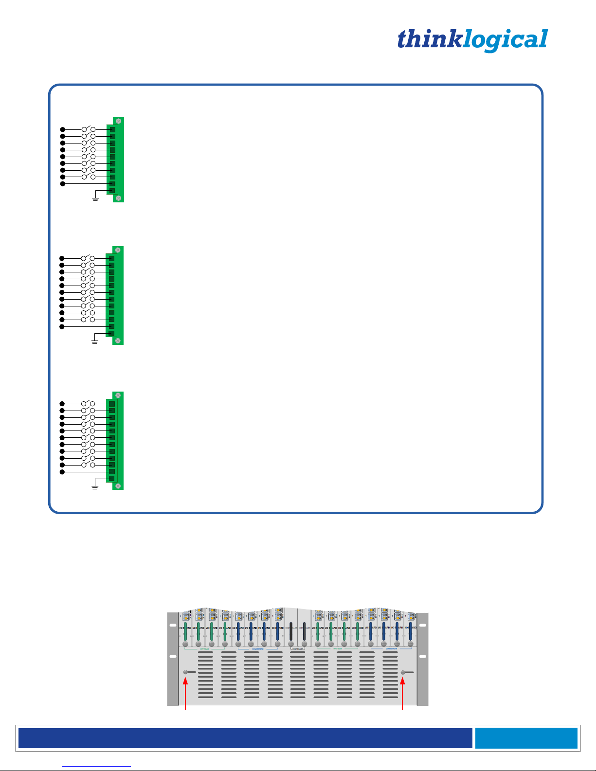
The VX Matrix Switches Critical Hardware Alarms are as follows:
1
2
3
4
5
6
7
8
9
10
11
12
POWER SUPPLY 1 (LEFT):
POWER SUPPLY 2:
FANS:
TEMPERATURE WARNING:
TEMPERATURE SHUTDOWN:
CPU:
INPUT/OUTPUT CARDS:
ANY OF THE ABOVE
SPARE
SPARE
COMMON
GROUND
The VX320 Matrix Switches Critical Hardware Alarms:
Individual fan monitoring
Chassis over temperature, multiple sensors
Chassis over temperature causing shutdown
Card failure (Only with a redundant card)
SFP+ failure, laser output fault
VX320VIDEO/AUDIO Router Power supplies, Left to Right:
1 Primary
2 Back-up
1
2
3
4
5
6
7
8
9
10
POWER SUPPLY 1 (LEFT):
POWER SUPPLY 2 (RIGHT):
FANS:
TEMPERATURE WARNING:
TEMPERATURE SHUTDOWN:
CPU:
INPUT/OUTPUT CARDS:
ANY OF THE ABOVE
COMMON
GROUND
The VX40, VX80 & VX160 Matrix Switches Critical Hardware Alarms:
Fan failure, temperature spikes, DC voltage/current range, AC power input interruption and module removed
Individual fan monitoring
Chassis over temperature, multiple sensors
Chassis over temperature causing shutdown
Card failure (Only with a redundant card)
SFP+ failure, laser output fault
1
2
3
4
5
6
7
8
9
10
11
12
POWER SUPPLY 1 (LEFT):
POWER SUPPLY 2:
POWER SUPPLY 3:
POWER SUPPLY 4 (RIGHT):
FANS:
TEMPERATURE WARNING:
TEMPERATURE SHUTDOWN:
CPU:
INPUT/OUTPUT CARDS:
ANY OF THE ABOVE
COMMON
GROUND
The VX320VIDEO/AUDIO Matrix Switches Critical Hardware Alarms:
Individual fan monitoring
Chassis over temperature, multiple sensors
Chassis over temperature causing shutdown
Card failure (Only with a redundant card)
SFP+ failure, laser output fault
VX320 Power supplies, Left to Right:
1 Upper Cabinet Primary
2 Upper Cabinet Back-up
3 Lower Cabinet Primary
4 Lower Cabinet Back-up
Fan failure, temperature spikes, DC voltage/current range, AC power input interruption and module removed
Fan failure, temperature spikes, DC voltage/current range, AC power input interruption and module removed
Fan failure, temperature spikes, DC voltage/current range, AC power input interruption and module removed
Fan failure, temperature spikes, DC voltage/current range, AC power input interruption and module removed
Fan failure, temperature spikes, DC voltage/current range, AC power input interruption and module removed
Fan failure, temperature spikes, DC voltage/current range, AC power input interruption and module removed
Fan failure, temperature spikes, DC voltage/current range, AC power input interruption and module removed
Alarm Descriptions for the VX40, VX160, VX320 and VX320Video/Audio
Adjustable Air Vents for the VX160
If the VX160 is mounted in a rack that restricts the front air intake, additional vents are located at the
bottom, rear of the VX160 chassis. Thumb screws open or close these vents to adjust air flow.
Page 20

®
VX Matrix Switch Manual Rev. Q October 2017
Page 19
The Controller Cards
The hot-swappable Controller Card connects the Matrix Switch to an external Linux or Windows CPU. The
serial port can also be used for 3rd party controller integration (such as Crestron, AMX or home-spun
interfaces). Also, the Configurator Software can be used to control the Matrix Switch via the LAN port. Please
note that there is a separate document for our Configurator Manual. It can be found on our website at
www.thinklogical.com. The VX320 and VX320VIDEO Matrix Switches require an OSD (On Screen Display)
version of the Controller Card for use with the Hot Key Manager: VXM-000031 (VX320) and VXM-000032
(VX320VIDEO).
FAULT: LED is ON= Card Failure
USB Port: Reserved
LAN: Connection to external CPU (RJ45)
RESET: Resets the CPU
CONSOLE PORT: Local debug
RS232: ASCII Control Interface
ACTIVE:
LED is ON= Controller Card is active
LED is OFF= Controller Card is in
standby or has failed
VX320
VX40/
VX80
VX160
CONSOLE
ACTIVE
RESET
FAULT
L
A
N
CONTROLLER
RS232
ACTIVE
FAULT
USB
LAN
RESET
CONSOLE
RS232
CONTROLLER
CONSOLE
ACTIVE
RESET
FAULT
L
A
N
CONTROLLER
RS232
External Control CPU
VXM-000005 VXM-000008 VXM-000001
Page 21
®
VX Matrix Switch Manual Rev. Q October 2017
Page 20
External CPU to Controller Cards
The Controller Cards of each VX Matrix Switch model connect the Matrix Switch to an External CPU.
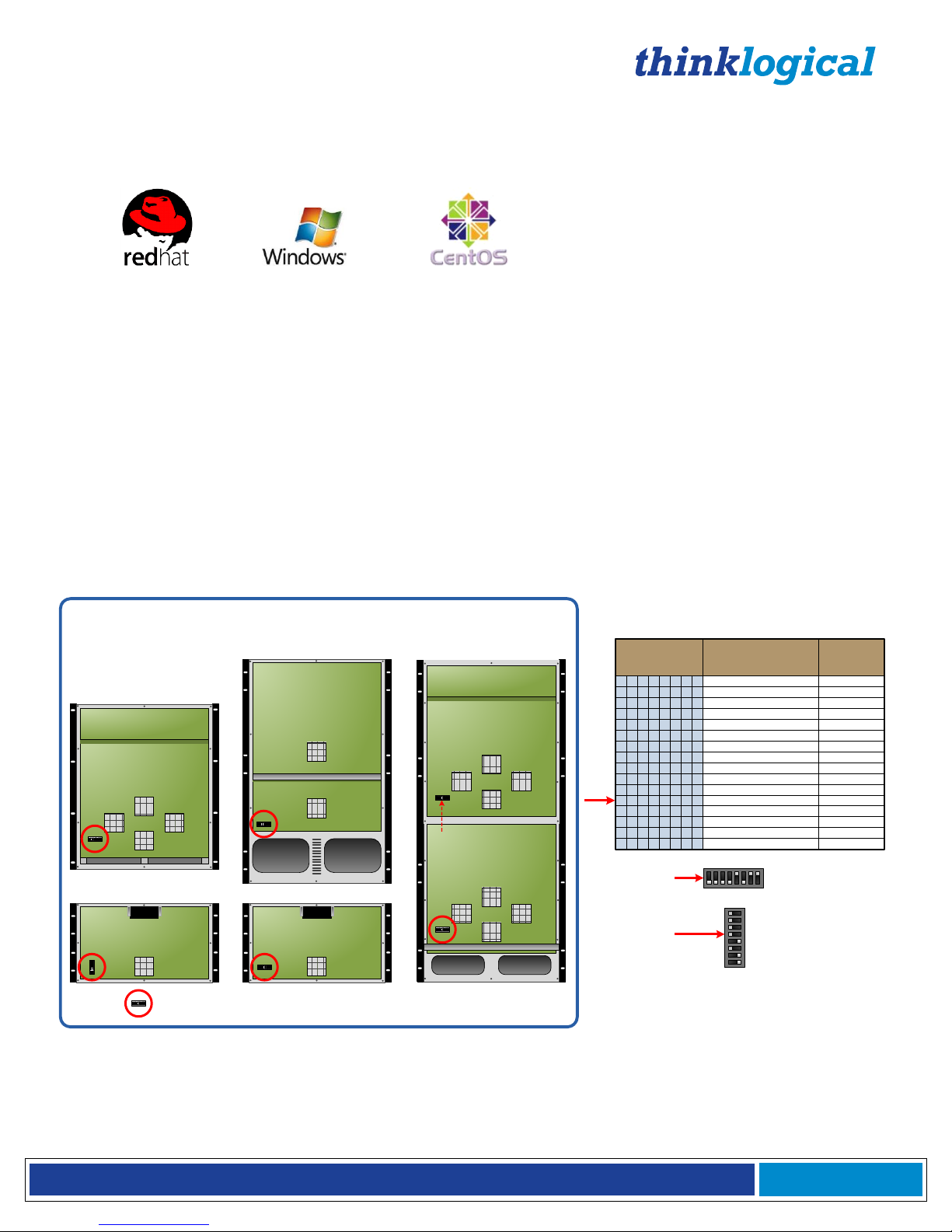
The External Control CPU must meet the following minimum requirements:
• RedHat EL5.3 or Windows or CentOS 5.3
• 1 Gig RAM
• 1 DVD drive
• VGA and/or DVI video port
• USB or PS2 Keyboard / Mouse
• 1 network port
• 80 Gig (minimum) hard drive
• 1 optional RS-232 serial port (Crestron/AMX serial access)
An optional Back-Up Controller Card ensures uninterrupted functionality if the Primary Controller Card ever
needs to be replaced.
VX Matrix Switch DIP Switch Settings
If the VX Matrix Switch is to be controlled via Ethernet, it will require a static IP address. This value can be set
via the DIP switch to the values listed below. The factory default setting is 192.168.13.15.
Back-up
Controller IP
Address
8 7 6 5 4 3 2 1
192.168.13.15 & 192.168.13.115
192.168.13.17 & 192.168.13.117
192.168.13.19 & 192.168.13.119
192.168.13.21 & 192.168.13.121
192.168.13.23 & 192.168.13.123
192.168.13.25 & 192.168.13.125
192.168.13.27 & 192.168.13.127
192.168.13.29 & 192.168.13.129
192.168.13.31 & 192.168.13.131
192.168.13.33 & 192.168.13.133
192.168.13.35 & 192.168.13.135
192.168.13.37 & 192.168.13.137
192.168.13.39 & 192.168.13.139
192.168.13.41 & 192.168.13.141
192.168.13.43 & 192.168.13.143
192.168.13.45 & 192.168.13.145
192.168.13.16
192.168.13.18
192.168.13.20
192.168.13.22
192.168.13.24
192.168.13.26
192.168.13.28
192.168.13.30
192.168.13.32
192.168.13.34
192.168.13.36
192.168.13.38
192.168.13.40
192.168.13.42
192.168.13.44
192.168.13.46
0 0 0 0 0 0 0 0
0 0 0 0 0 0 0 1
0 0 0 0 0 0 1 0
0 0 0 0 0 0 1 1
0 0 0 0 0 1 0 0
0 0 0 0 0 1 0 1
0 0 0 0 0 1 1 0
0 0 0 0 0 1 1 1
0 0 0 0 1 0 0 0
0 0 0 0 1 0 0 1
0 0 0 0 1 0 1 1
0 0 0 0 1 1 0 0
0 0 0 0 1 1 0 1
0 0 0 0 1 1 1 0
0 0 0 0 1 1 1 1
0 0 0 0 1 0 1 0
Primary Controller IP
Addresses
18
Pin 1 is on the right.
The up ↑ position = 1.
0 0 0 0 1 0 1 1
DIP Switch
Example:
1
8
0
0
0
0
1
0
1
1
Pin 1 is on the bottom.
The left ← position = 0.
(MX48, VX40, VX160,
VX160, VX320,
VX320A, VX320V)
DIP Switch
(VX80, VX640)
8 Position DIP Switch (Located on the lower left of the backplane on most VX Router models)
VXRouter DIP Switch Locations
VX160 Router with front
cover removed
VX80 Router with front
cover removed
VX320 Router with
front cover removed
VXVIDEO or AUDIO 320 Router
with front cover removed
(Non-functioning)
VX40 Router with front cover removed
VX Matrix Switch DIP Switch Locations and Setting
The simplest network connection is an isolated network with only the VX Matrix Switch, the control server, and
any control clients using static IP addresses. The VX Matrix Switch can be set to any of the above settings.
The control server must be at 192.168.13.9, and the control clients could then be set to any other addresses in
the 192.168.13.X family.
Page 22
®
VX Matrix Switch Manual Rev. Q October 2017
Page 21
If static IP addresses for the control server and its clients are not possible, then the control server will require
two (2) network interfaces with one interface set to the static address 192.168.13.9 and dedicated to the VX
Matrix Switch(s) while the other network interface can be configured as required by the facility's network
administrator.
A Back-Up Controller Card is optional to ensure uninterrupted functionality if the Primary Controller Card
should fail or need to be replaced. The Primary Controller Card should always be in the left or upper controller
slot. This card must have a LAN connection that allows communication between the Primary Controller and a
server having an IP address of 192.168.13.9. Without this interface, the back-up controller cannot take control
of the Matrix Switch. The server should have its firewall turned off or be configured so that it is able to respond
to pings from the Primary and back-up controllers.
Note: Removing the Primary Controller Card when it is Active will power down the VX Matrix
Switch and interrupt service. Refer to page 37 “How to Install or Replace a Controller Card”.
Note: When using a Back-up Controller configuration in a Secure Application with Restricted
Switching, both controllers must have the same Restricted Switching Table files (see Appendix D:
Secure Applications, page 57).
Input/Output Cards
The hot-swappable Input/Output (I/O) cards provide excellent in-service expansion capabilities in
convenient sets of 5 ports per I/O card for the VX40 and VX80, sets of 20 ports per I/O card for the
VX160 or sets of 16 ports per I/O card for the VX320s, thus allowing re-configuration without
interrupting signal processing.
Each I/O card consists of one Transmit (T) and one Receive (R) optic per port. I/O Cards are available
with LC-type fiber connectors and can be assembled with Single-mode or Multi-mode optics (SFP+).
Each individual I/O Card lists the ports as 1 through 5 on the VX40 and VX80, as 1 through 20 on the
VX160 and as 1 through 16 on the VX320 and VX320Video/Audio. The Fan Tray module lists the port
numbers
(All numbering is bottom-to-top, left-to-right. See Input/Output Port Numbering beginning on page
26). A LED located at the top of each I/O card indicates when power is ON to that card.
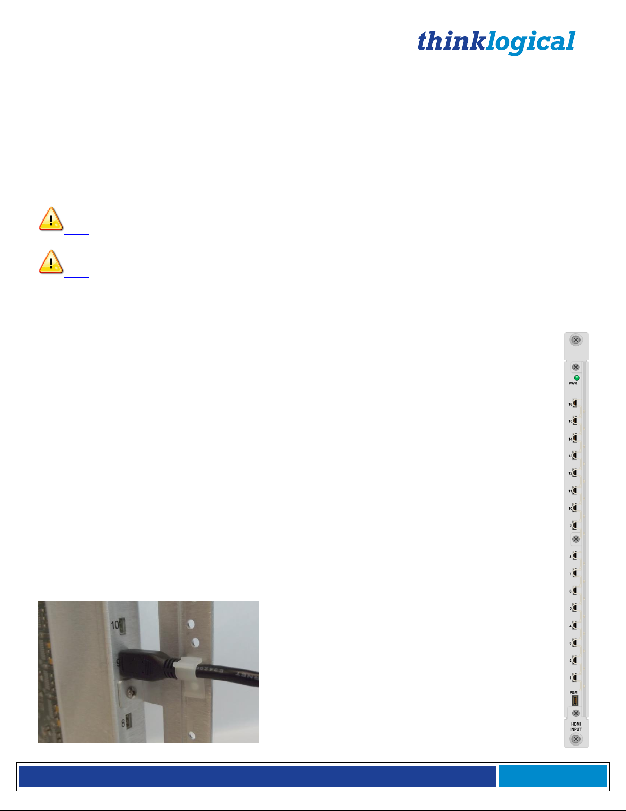
Micro-HDMI Input / EDID Output Cards
Also available, with the VX320Video Matrix Switch only, are HDMI Input Cards with Micro HDMI
connectors that support input cable lengths up to 15 meters and include a USB mini-B connector for
FPGA updates. These HDMI Input / EDID Output Cards (VXM-DH0016) are only compatible with a
TLX Controller Card. Please ask your Thinklogical sales rep for details. Sixteen 2-meter, micro-HDMI
to HDMI cables (CBL000107-002MR) are supplied with each card.
The built-in support bracket on the
VXM-DH0016 has convenient snap-on
clips to hold up to 16 cables per card
VXM-DH0016
Micro-HDMI I/O Card with cable guides, for use
in the VX320 Video Matrix Switch only.
Page 23

®
VX Matrix Switch Manual Rev. Q October 2017
Page 22
VX40 I/O Cards
The VX40 Matrix Switch consists of a single 80-input by 80-output, non-blocking switch matrix. This allows any
port on any I/O card (Upstream or Downstream) to be connected to any other port. The VX40 is designed so
that 8 I/O card slots on the left side are used for Upstream Cards and 8 I/O card slots on the right side are
used for Downstream Cards.
The Upstream and Downstream Cards are functionally equivalent. Either card can be used interchangeably for
routing signals, but they can only physically plug into their respective slots in the VX40 chassis. Thus, the
VX40 can connect any Upstream Port optical input or any Downstream Port optical input (SFP+ R) to any
Upstream and/or any Downstream Port optical output (SFP+ T). Figure 1 below depicts a bi-directional
connection from Upstream Port 1 to Downstream Port 1. This requires two switch connections, one from the
Upstream optical input to the Downstream optical output and one from the Downstream optical input to the
Upstream optical output.
Figure 1: VX40 Input/Output Concept
Page 24

®
VX Matrix Switch Manual Rev. Q October 2017
Page 23
VX80 I/O Cards
The VX80 Matrix Switch consists of a single 80 input by 80 output non-blocking switch matrix. This allows any
port on any I/O card to be connected to any other port. The VX80 is designed so that all 16 I/O card slots
accept the same type of card. The VX80 I/O card is functionally and physically the same as the VX40
Upstream Card. The VX80 Matrix Switch configuration can have a minimum of one I/O Card. Each VX80 I/O
card contains 5 ports, so that when fully configured, the VX80 will contain 16 I/O cards. The 16 I/O cards
provide a total of 80 Optical Input/Output connections (SFP+ T/R). The switching matrix connects any optical
input (SFP+ R) to any optical output (SFP+ T), even if it is the same Port number (i.e. Port 1 R connected to
Port 1 T).
Figure 2: VX80 Input/Output Concept
Page 25

®
VX Matrix Switch Manual Rev. Q October 2017
Page 24
VX160 I/O Cards
The VX160 contains two independent 160x160 fully non-blocking switch matrices. One switching matrix
connects any Upstream Port optical input (SFP+ R) to any Downstream Port optical output (SFP+ T). The
other switching matrix connects any Downstream Port optical input (SFP+ R) to any Upstream Port optical
output (SFP+ T). The VX160 Matrix Switch configuration must have a minimum of 1 Upstream Card (Green)
and 1 Downstream Card (Blue), each containing 20 ports. When fully configured, the VX160 will contain 8
Upstream cards and 8 Downstream cards. The 8 Upstream cards provide a total of 160 Optical Input/Output
connections (SFP+ T/R) described as Upstream Ports 1-160. The 8 Downstream cards provide a total of 160
Optical Input/Output connections (SFP+ T/R) described as Downstream Ports 1-160. Figure 3 depicts a
bidirectional connection from Upstream Port 1 to Downstream Port 1, showing downstream flow through one
160x160 fully non-blocking switch matrix, and upstream flow through another 160x160 fully non-blocking
switch matrix.
Figure 3: VX160 Input/Output Concept
Page 26

®
VX Matrix Switch Manual Rev. Q October 2017
Page 25
VX320 I/O Cards
The VX320 Matrix Switch configuration can have a minimum of one I/O Card in either the Upper Card Cage or
the Lower Card Cage. The VX320 Matrix Switch is constructed with one fully non-blocking 320x320 switch
matrix in the Upper Card Cage and another fully non-blocking 320x320 switch matrix in the Lower Card Cage.
Each VX320 I/O card contains 16 ports, so that when fully configured, the VX320 will contain 20 I/O cards in
the Upper Card Cage and 20 I/O cards in the Lower Card Cage. The 20 I/O cards in the Upper Card Cage
provide a total of 320 Optical Input/Output connections (SFP+ T/R) described as Upper Card Cage Ports 1-
320.
Similarly, the 20 I/O cards in the Lower Card Cage provide a total of 320 Optical Input/Output connections
(SFP+ T/R) described as Lower Card Cage Ports 1-320. The Upper Card Cage switching matrix connects any
Upper Card Cage Port optical input (SFP+ R) to any Upper Card Cage Port optical output (SFP+ T), even if it
is the same Port number (i.e. Port 1 R connected to Port 1 T). Similarly, the Lower Card Cage switching matrix
connects any Lower Card Cage Port optical input (SFP+ R) to any Lower Card Cage Port optical output (SFP+
T), even if it is the same Port number (i.e. Port 1 R connected to Port 1 T).
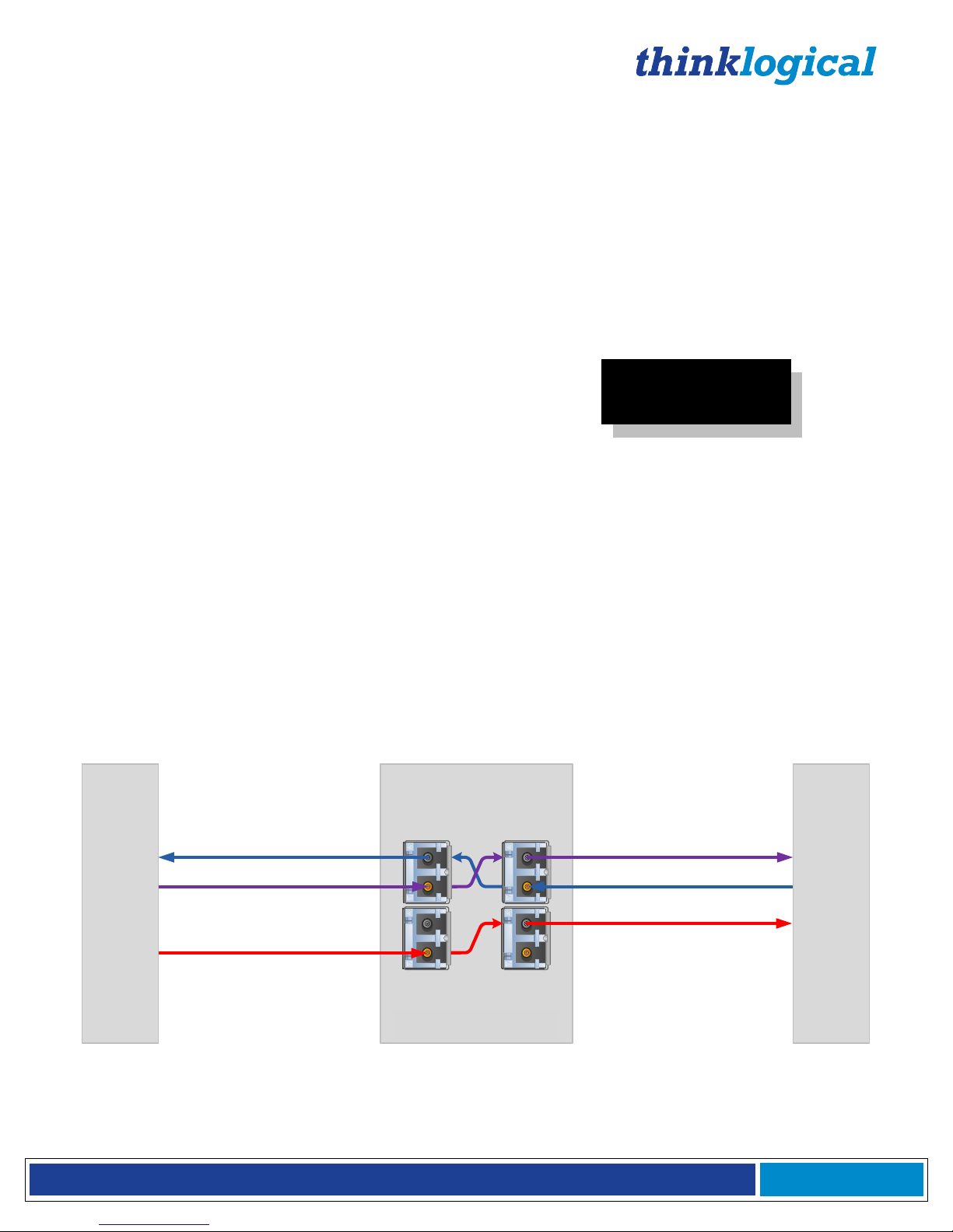
Figure 4 depicts a bidirectional connection. One direction is the connection from the Upper Card Cage Port
optical input (SFP+ R) to the Upper Card Cage Port optical output (SFP+ T), showing Video/Data flow from the
TX to the RX being routed through the Upper Card Cage 320x320 fully non-blocking switch matrix. The other
direction is the connection from the Lower Card Cage Port optical input (SFP+ R) to the Lower Card Cage Port
optical output (SFP+ T), showing the Data (KMASS) flow from the RX to the TX being routed through the
Lower Card Cage 320x320 fully non-blocking switch matrix.
Figure 4: VX320 Input/Output Concept
Page 27

®
VX Matrix Switch Manual Rev. Q October 2017
Page 26
Input/Output Port Numbering
VX40 Input / Output Port Numbering
VX80 Input / Output Port Numbering
VX160 Input / Output Port Numbering
Page 28

®
VX Matrix Switch Manual Rev. Q October 2017
Page 27
VX320 and VX320Video/Audio I/O Board Port Numbering (Same for Upper & Lower Card Cages)
Pluggable SFP+ Optical Modules
The SFP+ Optical Module is an 8Gb/s Short-Wavelength Transceiver designed for use in bi-directional Fiber
Optic Channel links. The modules are hot-pluggable and operate with 3.3VDC.
Each Input and Output card contains rows of SFP+ modules that serve as the fiber-optic couplers for the fiber
cables to and from the Thinklogical Tx and Rx Extenders. Individual cards can be removed for ease of access
to the SFP+ modules.
Each I/O card can have as many as 5 SFP+ modules for a VX40, 20 SFP+ modules for a VX160, and 16 SFP+
modules for a VX320 each mounted within a grounded metal enclosure. Each SFP+ module is locked into its
enclosure with a built-in latch handle that can be opened for removal or locked for installation.
The latch handle spans the two LC ports and arrows printed on the handle indicate which port is an INPUT
( ) and which is an OUTPUT ( ).
Always use dust caps to protect against damage when any fiber optic connector is not attached to
its coupling device.
SFP+ Module SFP+ with latch open Dust plug in unused SFP+
Note: It is good practice to immediately install dust plugs in unused SFP modules and on the
ferrules of unconnected fiber-optic cables.
Page 29

®
VX Matrix Switch Manual Rev. Q October 2017
Page 28
Fiber Optic Cable
Fiber Optic Cable Requirements
Thinklogical recommends SX+ Laser Enhanced (50µm) fiber for your VX Matrix Switch and Velocity Extension
System. Multi-mode fiber can extend up to a maximum of 1000m, where Single-mode fiber can extend
distances beyond 1000m.
Warning! Do not use APC (Angle Physical Contact) Connectors! If inserted into an SFP+, APCs
may damage the SFP+.
Handling Fiber Optic Cable
CLASS 1 LASERS do not require any special
precautions under conditions of normal use.
SFP
Modules
Fiber-Optic
Cables
Class 1 Lasers
Unlike copper cabling, fiber optic cable requires special handling. A small bit of dust or a scratch
on the ferrule tip can attenuate the optical signal so that it becomes unusable.
Warning! The ends of the connectors (the ferrule) should never contact any foreign object,
including fingertips.
Warning! Minimum bend radius must be 3”.
Be careful not to pinch or kink the fiber when
using ties.
3"
Page 30

®
VX Matrix Switch Manual Rev. Q October 2017
Page 29
Installing Fiber into Input/Output Cards
Step 1: Grasp the LC connector of the fiber optic cable by the sides and remove the dust cap.
Warning! Laser in use! Do not look directly into the opening.
Step 2: Carefully insert the fiber connector into the SFP+ port until it locks into place.
Removing Fiber from Input/Output Cards
Step 1: The LC connector has a locking feature that can be released by depressing the latch-release tab
located on the top of the connector. With the tab depressed, slowly remove the cable by pulling the connector
straight out of the SFP+ port.
Warning! Laser in use! Do not look directly into the opening.
Step 2: Immediately install a dust cap on the ferrule to protect the fiber tip and install a dust cap into the SFP if
another fiber is not immediately installed.
Connecting to Thinklogical Velocity Extenders
VX Matrix Switches are designed to work with any Thinklogical product designed with the MRTS technology
(e.g. Velocity Extenders). VX Matrix Switches and Velocity Extenders are a new, unique class of cost-effective
matrix switching and KVM extension designed for a variety of high-performance computing environments.
Comprised of a fiber-in, fiber-out matrix switch and a fiber-optic KVM extender (with a transmitter and receiver),
this complete system provides transparent and secure routing, switching and extension of video and highspeed data peripherals to remote destinations with ease.
BEFORE STARTING ANY PROCEDURE, IT IS RECOMMENDED
THAT YOU READ THE INSTRUCTIONS THOROUGHLY!
Connecting to the Receiver
The Velocity Receiver serves as the Destination (desktops, theaters, conference rooms, editing suites, control
consoles, video walls, etc.). Depending on your configuration, your KMASS devices (audio, keyboard, mouse,
etc.) are first connected to the Receiver using standard cables. Power can then be supplied to the unit. The
Receiver then connects to the VX Matrix Switch SFP+ ports using fiber (Multi-mode fiber for distances up to
1000m; Single-mode fiber for distances beyond 1000m).
Page 31

®
VX Matrix Switch Manual Rev. Q October 2017
Page 30
5
4
3
2
1
T
R
T
R
T
R
POWER
Monitor, Projector and
Audio Destinations
U
P
D
A
T
E
S
LINE OU
T
MIC I
N
P
S
2
USB HID
HOS
T
CNTRL
SER IAL POR
T
DVI OUT 1
DVI OUT 2
DVI OUT 2 DDC
DVI OUT 1 DDC
L
2
L
1
L
3
AUDIO
Velocity kvm- 24RECEIVER
L1: Video 1 and Dat
a T
x
(Upstream) to R
x
L2: Data Rx
(Downstream) to T
x
L
3:
Video 2
DVI OUT 1
DVI OUT 2
L
1
L
2
L
3
Connecting the Thinklogical VelocityKVM-24 Extender Receiver to the VX40/VX80
Page 32

®
VX Matrix Switch Manual Rev. Q October 2017
Page 31
POWER
20
19
18
17
16
15
14
13
12
11
10
9
8
7
6
5
4
3
2
1
I/ O BOARD
T
R
T
R
Monitor, Projector and
Audio Destinations
U
P
D
A
T
E
S
LINE OU
T
MIC I
N
P
S
2
USB HID
HOS
T
CNTRL
SER IAL POR
T
DVI OUT 1
DVI OUT 2
DVI OUT 2 DDC
DVI OUT 1 DDC
L
2
L
1
L
3
AUDIO
L
1
L
2
L
3
Velocity kvm- 24RECEIVER
L1: Video 1 and Data Tx
(Upstream) to R
x
L2: Data Rx
(Downstream
) t
o T
x
L3: Video 2
DVI OUT 1
DVI OUT 2
Connecting the Thinklogical VelocityKVM-24 Extender Receiver to the VX160
Page 33

®
VX Matrix Switch Manual Rev. Q October 2017
Page 32
Connecting to the Transmitter
The Transmitter serves as the Source (computer and video entities). Depending on your configuration, your
local KMASS devices (keyboard, mouse, etc.) are first connected. The video sources (e.g. computers) are then
connected followed by any local video devices. Power can then be supplied to the unit. The Transmitter
connects to the VX160 Upstream ports using fiber (Multi-mode fiber for distances up to 1000m; Single-mode
fiber for distances beyond 1000m).
DVI
IN 1
DVI
IN
2
USB HID, PS/2 (Keyboard/Mouse)
Velocity kvm
Audio IN/OUT
DEV
L
INE I
N
MIC OUT
HID
P
S
2
LOCALFROM CPU
USB HID
HOS
T
CNT
R
L
UPDATES
SER IAL POR
T
DVI OUT 1
DVI OUT 2
DVI IN
2
DVI IN
1
KMASS
LOCAL KEYBOARD/MOUSE
-
24
TRANSMITTER
L1: Video 1 and Dat
a T
x (Upstream
) t
o R
x
L2: Data Rx (Downstream) to T
x
L3: Video 2
SOURC
E
CPU
DVI OUT 1
DVI OUT
2
5
4
3
2
1
T
R
T
R
T
R
T
R
T
R
POWER
L
2
L
1
L
3
L
1
L
2
L
3
Connecting the Thinklogical VelocityKVM-24 Extender Transmitter to the VX40/VX80
Page 34

®
VX Matrix Switch Manual Rev. Q October 2017
Page 33
T
R
T
R
POWER
20
19
18
17
16
15
14
13
12
11
10
9
8
7
6
5
4
3
2
1
I/ O BOARD
DVI
IN 1
DVI
IN
2
USB HID, PS/2 ( Keyboard / Mouse)
Velocity kvm
Audio IN/OUT
DEV
L
INE I
N
MIC OUT
HID
P
S
2
LOCALFROM CPU
USB HID
HOS
T
CNT
R
L
UPDATES
SER IAL POR
T
DVI OUT 1
DVI OUT 2
DVI IN
2
DVI IN
1
L
2
L
1
L
3
KMASS
LOCAL KEYBOARDMOUSE
L
1
L
2
L
3
-
24
TRANSMITTER
L1: Video 1 and Data Tx (Upstream) to R
x
L
2: Data Rx (Downs
t
r
eam) to T
x
L3: Video 2
SOURC
E
CPU
DVI OUT 1
DVI OUT
2
Connecting the Thinklogical VelocityKVM-24 Extender Transmitter to the VX160
Page 35

®
VX Matrix Switch Manual Rev. Q October 2017
Page 34
VelocityKVM-4 Transmitter VelocityKVM-4 Receiver
POWER
16
15
14
13
12
11
10
T
R
POWER
16
15
14
13
12
11
10
T
R
Port
pairs
16
1
Port
pairs
16
1
100
-
240V-
,0.5A, 50
/
60
Hz
T
2
A ,250
VAC
CAUTION
!
Replace with same type and rating fuse
.
CNTRL
LINE OUT
HOST
USB HID
U
P
D
A
T
E
S
PWR
FOL
USB
2.0
SER IAL PORT
L
1
DVI OUT DDC
DVI OUT
P
S
2
USB1.
1
MIC IN
L
2
UPDATES
DEV
DVI OUT
DVI IN
SER IAL PORT
L
2
L
1
LINE IN
MIC OUT
HID
P
S
2
LOCAL
FROM CPU
USB1.
1
USB HID
HOST
CNTRL
CAUTION
!
Replace with same type and rating fuse
.
100-240
V-,0.5A
, 50/
60
Hz
T 2A ,250
VAC
CLINK
PWR
CP
FOL
T
R
Video/Data from Tx
Video/Data to Rx
Upper Card Cage*
Any Card, 1-20
Any Port pair, 1-16
Crosspoint
Switch
UPPER
CARD
CAGE
LOWER
CARD
CAGE
T
R
Data from Rx
Data to Tx
Any Card, 1-20
Any Port pair, 1-16
Crosspoint
Switch
Lower Card Cage*
VX320
*Both the Upper and
Lower Card Cages
are designed to
handle either Video
or Data signals.
(320 Ports)
(320 Ports)
VIDEO + DATA
(USB 2.0, USB 1.1,
USB 1.0, Audio,
Serial, PS2)
DATA (USB 2.0, USB 1.1,
USB 1.0, Audio, Serial, PS2)
DATA (USB 2.0, USB 1.1,
USB 1.0, Audio, Serial, PS2)
VIDEO + DATA (USB 2.0, USB 1.1, USB 1.0, Audio, Serial, PS2)
Connecting the Thinklogical VelocityKVM-4 Extender Transmitter and Receiver to the VX320
Page 36

®
VX Matrix Switch Manual Rev. Q October 2017
Page 35
Installation
All physical connections to the product use industry-standard connectors. Non-supplied cables that may be
needed are commercially available. All connections are found on the rear of the unit.
VX40
router
Up to 40 DESTINATIONS
SOURCE
Velocitydvi-3A/V+ DVI Display
Transmitter
Velocitydvi-3A/V+ DVI Display
Receivers 1, 2 & 3...
VX40 KVM Matrix Switch application
using Thinklogical’s
Velocitydvi-3A/V+ DVI Display
Extenders
Network
Hub
Supports up to 40
sources & destinations
KVM Matrix Switch
3
21
Customer
Supplied
Computer
Typical VX40 Matrix Switch Application using VelocityDVI-3AV+ Extenders
Set-Up
Note: Insure that all thumb screws are finger tight so that all the modules are properly held in
the chassis.
1. Carefully remove the VX Matrix Switch from its shipping container. Inspect the VX Matrix Switch
to make certain that no damage occurred during shipment.
2. All I/O cards are installed at the factory to meet the customer’s specified configuration. Insure
that the I/O cards are properly seated in the unit. All I/O cards have thumb screw retainers. All
SFP+ Modules should have a dust plug installed. Leave them in until that port is in use.
(Retain them for later use.)
3. After checking the I/O cards, inspect the upper part of the unit. There are two (VX40, 80, 160) or
four (VX320 & 320Video/Audio) power supplies located in the upper chassis. Verify that the
power supplies are secure in the chassis.
4. Located directly below the power modules is the fan tray which has thumb screws holding it in
place. Verify that the fan tray is secure. Cooling is accomplished by three fans in the tray, air
baffles in the chassis door and fans in each of the power supply units. Air is forced into the
chassis from the fan tray which cools the vertically mounted I/O cards and the integrated
circuits on the Backplane, as well as removing any heat generated by the power modules.
Page 37

®
VX Matrix Switch Manual Rev. Q October 2017
Page 36
Warning! Do not open or remove the Front Door when the unit is powered. The door of each VX
Matrix Switch contains air baffles that are integral to the chassis’ cooling system. The
Backplane Integrated Circuits may overheat when operating with the front door open or
removed.
Note: When mounting the chassis in a rack, insure that the fans’ air flow is not restricted.
5. The temperature in the chassis is monitored in several locations. The power supplies have an
internal temperature sensor that is monitored constantly for any conditions that may
indicate a problem. Other temperature sensors are mounted in the fan trays, on the
Controller card(s), on the I/O cards, and on the Backplane.
Note: If any of these sensors detect an over temperature condition, power will be removed from
all sensitive components and the system will shut down.
6. As a further safeguard, all fan speeds are monitored and any fan speed that does not meet
specification will cause the unit to set an alarm condition.
Note: All failure conditions send out notifications prior to shut down. For a detailed list of the
alarm descriptions, see page 17.
7. When the VX Matrix Switch has been inspected and found to be in good condition, the
installation process can begin.
Order of Installation Events
Please refer to the Quick Start Guides included with your products for detailed instructions. VX Matrix
Switch Quick Start Guides are also available in Appendix B, page 47.
How to Replace Modules
How to Install or Replace Input/Output Cards
Note: No shutdown is required prior to installing/replacing Input/Output Cards.
Step 1: Turn the two thumbscrews counterclockwise until they disengage from the chassis. Pull the card out
using both handles.
Warning! Do not pull on the thumbscrews when removing the module – damage may occur!
OR: If a blank panel is present, remove the blank panel from the desired location using the thumbscrews.
Step 2: Place the new module upright so that the POWER LED is on the top. Grasp the module by
the handles or by the outer edge of the aluminum housing. The card should slide freely until it
reaches the backplane connector. At this point, use just enough force to firmly engage the card with
the mating connector.
Warning! If the module does not slide into the connector, do not force it! Damage may occur.
Remove the card and start over.
Step 3: Once the module is completely seated, hand-tighten the thumbscrews.
Warning! Do not tighten the thumbscrews with a screwdriver.
Page 38

®
VX Matrix Switch Manual Rev. Q October 2017
Page 37
How to Install or Replace a Controller Card
Note: When using a single Controller, the left or upper Controller slot is always Primary.
Note: Replacing the Active Controller Card will interrupt service.
When replacing a Controller Card in a system with redundant controllers you may remove the
Controller that is not active (Active LED is off) without interrupting service.
Step 1: Before removing a Primary Controller that is active you should cause a Fail-over to the Back-up
Controller. This can be done by removing the LAN connection from the active Controller and waiting approximately 20-50 seconds for the Back-up Controller to take control, as indicated by the Active LED. After the
Primary Controller is removed and replaced (following the steps 2-5), the Primary Controller will re-take control
of the system and become the Active Controller.
Step 2: Turn the thumbscrews counterclockwise until they disengage from the chassis. Pull the Controller Card
out using both black handles.
Step 3: Place the new module upright so that the ACTIVE LED is on the top. Grasp the module by the
handles or by the outer edge of the aluminum housing. The card should slide freely until it reaches the
backplane connector. Use just enough force to firmly engage the card with the mating connector.
Warning! If the module does not slide easily into the connector, do not force it! Damage may
occur. Remove the card and start over.
Step 4: Once the module is completely seated, hand-tighten the thumbscrews.
Warning! Do not tighten the thumbscrews with a screwdriver.
Step 5: Replace the RJ45 CAT5 LAN cable connection and/or the RS232 cable connection.
How to Replace a Fan Tray
Each of the VX Matrix Switches uses three DC fans to move air horizontally through the enclosure. Be sure to
not block the air vents on the front or rear of the unit and leave at least 2” of space on both sides.
Note: Be sure to leave adequate ventilation space on both sides of the units (2” minimum),
especially if the transmitters or receivers (e.g. Extenders) are being stacked above or below the
VX Matrix Switch.
Note: No shutdown is required prior to replacing the Fan Tray, but operating without fans for
more than a few minutes is not recommended.
Step 1: Turn the four thumbscrews counterclockwise until they disengage from the chassis.
Step 2: Pull the Fan Tray module out using both black handles.
Step 3: Place the new module so that the aluminum housing is on the bottom. Hold the new Fan Tray by
the handles and slide the aluminum housing into the card guides.
Warning! Do not operate the unit for an extended period without a Fan Tray installed.
Step 4: Hand-tighten the thumbscrews.
Warning! Do not tighten the thumbscrews with a screwdriver.
Page 39

®
VX Matrix Switch Manual Rev. Q October 2017
Page 38
How to Replace a Power Supply
Warning! Disconnect the power cord before proceeding!
Note: No shutdown is required prior to replacing a Power Supply.
The Power Modules are universal input 120-240VAC, 50-60Hz. Use the proper power cord for your region
(supplied with the unit). Although the VX Matrix Switch functions properly with one power module, it is
recommended that both modules be used, preferably connected to two independent power sources (for
redundancy).
Step 1: Grasp the handle with one hand.
Step 2: Slide the green tab to the left with the other hand.
Step 3: Pull the Power Module out of the chassis.
Step 4: Insert the new Power Module into the chassis and slide it in until it reaches the backplane connector.
The module should slide freely until it reaches the backplane connector. Use just enough force to
firmly engage the card with the mating connector.
Warning! If the module does not slide easily into the connector, do not force it! Damage may
occur. Remove the module and start over.
Part 2: Regulatory & Safety Requirements
Symbols Found on the Product
Markings and labels on the product follow industry-standard conventions. Regulatory markings found on the
products comply with domestic and many international requirements.
Regulatory Compliance
Thinklogical’s® products are designed and made in the U.S.A. These products have been tested by a certified
testing laboratory and found to be compliant with the following standards (both domestic USA and many
international locations):
North America
Safety
ANSI/UL60950-1: 1st Edition (2003)
CAN/CSA C22.2 No. 60950-1-03
CENELEC EN 60950-1, 1st Edition (2001)
LASER Safety
CDRH 21CFR 1040.10
Class 1 LASER Product
IEC60825:2001 Parts 1 and 2
Class 1 LASER Product
Electromagnetic Interference
FCC CFR47, Part 15, Class A
Industry Canada ICES-003 Issue 2, Revision 1
Page 40

®
VX Matrix Switch Manual Rev. Q October 2017
Page 39
Australia & New Zealand
This is a Class A product. In a domestic environment this product may cause radio interference, in which case
the user may be required to take adequate measures.
European Union
Declaration of Conformity
Manufacturer’s Name & Address: Thinklogical, A BELDEN BRAND
100 Washington Street
Milford, Connecticut 06460 USA
These products comply with the requirements of the Low Voltage Directive 72/23/EEC and the EMC Directive
89/336/EEC.
Standards with Which Our Products Comply
Safety
CENELEC
IEC 60950-1 2nd Ed. 2005
Electromagnetic Emissions
EN55022: 1994 (IEC/CSPIR22: 1993)
EN61000-3-2/A14: 2000
EN61000-3-3: 1994
Electromagnetic Immunity
EN55024: 1998 Information Technology Equipment-Immunity Characteristics
EN61000-4-2: 1995 Electro-Static Discharge Test
EN61000-4-3: 1996 Radiated Immunity Field Test
EN61000-4-4: 1995 Electrical Fast Transient Test
EN61000-4-5: 1995 Power Supply Surge Test
EN61000-4-6: 1996 Conducted Immunity Test
EN61000-4-8: 1993 Magnetic Field Test
EN61000-4-11: 1994 Voltage Dips & Interrupts Test
Supplementary Information
The following statements may be appropriate for certain geographical regions and might not apply to your
location:
This Class A digital apparatus meets all requirements of the Canadian Interference-Causing Equipment
Regulations.
Cet appareil numérique de la classe A respecte toutes les exigencies du Règlement sur le matérial
brouilleur du Canada.
Warning! This is a Class A product. In a domestic environment, this product may cause radio
interference, in which case the user may be required to take corrective measures.
Note: This equipment has been tested and found to comply with the limits for a Class A digital
device, pursuant to part 15 of the FCC Rules. These limits are designed to provide reasonable
protection against harmful interference when the equipment is operated in a commercial
environment. This equipment generates, uses and can radiate radio frequency energy and, if
not installed and used in accordance with the instruction manual, may cause harmful
interference to radio communications in which case the user may be required to take adequate
corrective measures at their own expense.
Page 41

®
VX Matrix Switch Manual Rev. Q October 2017
Page 40
Note: This Class A digital apparatus complies with Canadian ICES-003 and has been verified as
being compliant within the Class A limits of the FCC Radio Frequency Device Rules (FCC Title
47, Part 15, Subpart B CLASS A), measured to CISPR 22: 1993 limits and methods of
measurement of Radio Disturbance Characteristics of Information Technology Equipment.
Note:
The user may notice degraded audio performance in the presence of electro-magnetic
fields
.
Product Serial Number
Thinklogical products have a unique serial number, which includes a date-code, printed on an adhesive label
that is affixed to the unit. The format for the date-code is 2 digits for the month, dash, 2 digits for the year, plus
at least four digits for a unique unit number. For example:
04-170128 indicates the unit was built in the 4th month of 2017, and is unit number 128.
Connection to the Product
Connections and installation hardware for our products use industry-standard devices and methods.
All wiring connections to the customer equipment are designed to minimize proprietary or customized
connectors and cabling. Power connections are made with regionally appropriate power cords and approved
methods.
Section 3: Thinklogical Support
Customer Support
Thinklogical® is an engineering company and you will receive any help you need directly from our
most knowledgeable engineers.
We believe that the first line of support comes from the design
engineers that developed each particular product.
Therefore, your questions or issues will be handled promptly by our in-house engineers who are most familiar
with your products.
Thank you for choosing Thinklogical® products for your application.
We appreciate your business and are dedicated to helping you successfully use our products.
is always here to help you.
To contact us, please use the following telephone numbers and internet-based methods:
®
Website
Check out our website for current product offerings, support information and general information about all the
products we offer.
Our internet website offers product information on all current systems, including technical specification sheets
and installation guides (for viewing online or for download), product diagrams showing physical connections
and other useful information.
Internet: www.thinklogical.com
Note: Most online documents are stored as Adobe Acrobat “PDF” files. If you do not have the
Adobe Acrobat reader needed to view PDF files, visit www.adobe.com for a download.
Page 42

®
VX Matrix Switch Manual Rev. Q October 2017
Page 41
Email
Thinklogical is staffed Monday through Friday from 8:30am to 5:00pm, Eastern Time Zone. We will do our
best to respond to your email inquiries promptly. Please use the following email addresses:
info@thinklogical.com – Information on Thinklogical and our products.
sales@thinklogical.com – Sales Department - orders, questions or issues.
support@thinklogical.com – Product support, technical issues or questions, product
repairs and request for Return Authorization.
Telephone
Thinklogical Operator 1-203-647-8700
Product & Customer Support: 1-203-647-8798
US Commercial & Canada Sales: 1-203-647-8715
US Federal Government Sales: 1-203-647-8716
Toll Free in the Continental US: 1-800-291-3211
International Sales (Europe, Middle East, Africa): 1-203-647-8704
International Sales (Asia Pacific, Central & Latin America): 1-203-647-8734
Please contact our expert sales staff in Milford, CT. We are here Monday through Friday from 8:30am to
5:00pm, Eastern Time Zone. We’ll provide a representative’s direct dial phone number when you call.
If leaving a voice message, please provide a preferred time to call back so we may reach you at your
convenience.
Our switchboard attendant will direct your call during regular business hours. We have an automated attendant
answering our main telephone switchboard after regular business hours and holidays. Please leave voice
messages for individuals at any time.
Fax
Our company facsimile number is 1-203-783-9949. Please indicate the nature of the fax on your cover sheet
and provide return contact information.
Product Support
Thinklogical’s support personnel are available Monday through Friday from 8:30am to 5:00pm, Eastern
Time Zone. If your application requires assistance at some time outside of our normal business hours, please
contact us beforehand and we will do our best to help you with your Thinklogical products.
Warranty
Thinklogical warrants this product against defects in materials and workmanship for a period of one year from
the date of delivery. Thinklogical and its suppliers disclaim all other warranties.
Note: Thinklogical® products carry a one-year warranty, with longer term available at time of
purchase on most products. Please refer to your product invoice for your products Warranty
Terms & Conditions.
Defect remedy shall be the repair or replacement of the product, provided that the defective product is returned
to the authorized dealer within a year from the date of delivery.
If you wish to return your device, contact the Thinklogical authorized dealer where you purchased the device,
or if you purchased directly, call Thinklogical® at 1-800-291-3211 (USA).
Page 43

®
VX Matrix Switch Manual Rev. Q October 2017
Page 42
Return Authorization
If you need to return your Thinklogical® product to us for any reason, please get a
Return Merchandise Authorization Number (RMA#)
from Thinklogical’s Product Support Department (1-203-647-8798) before sending the unit in.
In the event you must return a product to Thinklogical® directly, please contact Customer Support at 1-800-
291-3211 or 1-203-647-8700. Customer Support will ask you to describe the problem and will issue you a
Return Merchandise Authorization number (RMA#). Pack the device in its original box, if possible, and return it
with the RMA# printed on the outside of the box.
Note: DO NOT return a product to Thinklogical® without a Return Merchandise Authorization.
Our Addresses
If you have any product issues or questions or need technical assistance with your Thinklogical® system,
please call us at 1-800-291-3211 (USA only) or 1-203-647-8700 and let us help. If you need to write us or
return a product, please use the following address: Return address for products with Return Merchandise
Authorization: Thinklogical, A BELDEN BRAND
Attn: RMA#
100 Washington Street
Milford, CT 06460 USA
Website: www.thinklogical.com
Facebook: www.facebook.com/ThinklogicalUSA
LinkedIn: www.linkedin.com/company/thinklogical
Google+: http://plus.google.com/u/0/109273605590791763795/about
YouTube: www.youtube.com/user/thinklogicalNA
Twitter: @thinklogical
Page 44

®
VX Matrix Switch Manual Rev. Q October 2017
Page 43
Appendix A: Ordering Information
VX40 and VX80 Matrix Switches
Thinklogical's VX40 Matrix Switch Ordering Information
Part Number
Description
Velocity Matrix Switch 40
VXR-000040
Velocity Matrix Switch 40 Chassis
VXR-000040 REV B
Velocity Matrix Switch 40 Chassis, Common Criteria EAL 4 Certified
Velocity Matrix Switch 40 Data Cards
VXM-DI0005
Velocity Matrix Switch 40 Data Upstream Card, 5 Ports, SFP+, Multi-mode
VXM-DI0005 REV A
Velocity Matrix Switch 40 Data Upstream Card, 5 Ports, SFP+, Multi-mode, Common
Criteria EAL 4 Certified
VXM-DO0005
Velocity Matrix Switch 40 Data Downstream Card, 5 Ports, SFP+, Multi-mode
VXM-DO0005 REV A
Velocity Matrix Switch 40 Data Downstream Card, 5 Ports, SFP+, Multi-mode, Common
Criteria EAL 4 Certified
VXM-DI0S05
Velocity Matrix Switch 40 Data Upstream Card, 5 Ports, SFP+, Single-mode
VXM-DO0S05
Velocity Matrix Switch 40 Data Downstream Card, 5 Ports, SFP+, Single-mode
VXM-DI0E05
Velocity Matrix Switch 40 Vacant Data Input Card, 5 Ports, No SFP+
VXM-DO0E05
Velocity Matrix Switch 40 Vacant Data Output Card, 5 Ports, No SFP+
Velocity Matrix Switch 40 Spares
VXM-000005
Velocity Matrix Switch 40/80 Controller Card
VXM-000006
Velocity Matrix Switch 40 Fan Tray
VXM-000007
Velocity Matrix Switch 40/80 Power Supply
VXM-000271
Velocity Matrix Switch 40 Backplane
Thinklogical's VX80 Matrix Switch Ordering Information
Part Number
Description
VXR-000080
Velocity Matrix Switch 80 Chassis
VXM-000005
Velocity Matrix Switch 40/80 Controller Card
VXM-00RSD5
Velocity Matrix Switch 40/80 Controller Card with removable SD card
VXM-000007
Velocity Matrix Switch 40/80 Power Supply
VXM-000019
Velocity Matrix Switch 80 Fan Tray
VXM-000029
Velocity Matrix Switch 80 Backplane
VXM-D00005
Velocity Matrix Switch 80 Data Input/Output Card, 5 ports, SFP+, Multi-mode
VXM-D00C05
Velocity Matrix Switch 80 Data Input/Output Card, 5 Ports, Coaxial
VXM-D00E05
Velocity Matrix Switch 80 Data Input/Output Card, 5 Ports, No SFP+
VXM-D00S05
Velocity Matrix Switch 80 Data Input/Output Card, 5 Ports, SFP+, Single-mode
Page 45

®
VX Matrix Switch Manual Rev. Q October 2017
Page 44
VX160 Matrix Switches
Thinklogical's VX160 Matrix Switch Ordering Information
Part Number
Description
Velocity Matrix Switch 160
VXR-000160
Velocity Matrix Switch 160 Chassis
VXR-000160 REV B
Velocity Matrix Switch 160 Chassis, Common Criteria EAL 4 Certified
Velocity Matrix Switch 160 Data Cards
VXM-DI0020
Velocity Matrix Switch 160 Data Upstream Card, 20 Ports, SFP+, Multi-mode
VXM-DI0020 REV B
Velocity Matrix Switch 160 Data Upstream Card, 20 Ports, SFP+, Multi-mode, Common
Criteria EAL 4 Certified
VXM-DO0020
Velocity Matrix Switch 160 Data Downstream Card, 20 Ports, SFP+, Multi-mode
VXM-DO0020 REV B
Velocity Matrix Switch 160 Data Downstream Card, 20 Ports, SFP+, Multi-mode,
Common Criteria EAL 4 Certified
VXM-DI0S20
Velocity Matrix Switch 160 Data Upstream Card, 20 Ports, SFP+, Single-mode
VXM-DO0S20
Velocity Matrix Switch 160 Data Downstream Card, 20 Ports, SFP+, Single-mode
VXM-DI0E20
Velocity Matrix Switch 160 Vacant Data Input Card, 20 Ports, No SFP+
VXM-DO0E20
Velocity Matrix Switch 160 Vacant Data Output Card, 20 Ports, No SFP+
VXM-DI0R20
Velocity Matrix Switch 160 Data Input Repeater Card, 20 Ports, SFP+, Multi-mode
Velocity Matrix Switch 160 Spares
VXM-000001
Velocity Matrix Switch 160 Controller Card
VXM-000002
Velocity Matrix Switch 160 Fan Tray
VXM-000003
Velocity Matrix Switch 160 Power Supply
Page 46

®
VX Matrix Switch Manual Rev. Q October 2017
Page 45
VX320, VX320Video and VX320Audio Matrix Switches
Thinklogical's VX320 Matrix Switch Ordering Information
Part Number
Description
Velocity Matrix Switch 320
VXR-000320
Velocity Matrix Switch 320 Chassis
VXR-000320 REV A
Velocity Matrix Switch 320 Chassis, Common Criteria EAL 4 Certified
Velocity Matrix Switch 320 Data Cards
VXM-D00016
Velocity Matrix Switch 320 Data Upstream/Downstream Card, 16 Ports, SFP+, Multi-mode
VXM-D00016 REV A
Velocity Matrix Switch 320 Data Upstream/Downstream Card, 16 Ports, SFP+, Multi-mode,
Common Criteria EAL 4 Certified
VXM-D00S16
Velocity Matrix Switch 320 Data Upstream/Downstream Card, 16 Ports, SFP+, Singlemode
VXM-D00E16
Velocity Matrix Switch 320 Vacant Data Upstream/Downstream Card, 16 Ports, No SFP+
VXM-D00R16
Velocity Matrix Switch 320 Data In/Out Repeater Card, 16 Ports, SFP+, Multi-mode
VXM-D00T16
Velocity Matrix Switch 320 Data In/Out Re-timer Card, 16 Ports, SFP+, Multi-mode
Velocity Matrix Switch 320 Spares
VXM-000008
Velocity Matrix Switch 320 Controller Card
VXM-000031
Velocity Matrix Switch 320 Controller Card with OSD
VXM-000009
Velocity Matrix Switch 320 Fan Tray
VXM-000010
Velocity Matrix Switch 320 Power Supply
Thinklogical's VX320VIDEO Matrix Switch Ordering Information
Part Number
Description
Velocity Matrix Switch 320Video
VXR-V00320
Velocity Matrix Switch 320 VIDEO Chassis
Velocity Matrix Switch 320Video Data Cards
VXM-D00016
Velocity Matrix Switch 320V Data Upstream/Downstream Card, 16 Ports, SFP+, Multi-mode
VXM-D00S16
Velocity Matrix Switch 320V Data Upstream/Downstream Card, 16 Ports, SFP+, Single-mode
VXM-D00E16
Velocity Matrix Switch 320V Vacant Data Upstream/Downstream Card, 16 Ports, No SFP+
VXM-D00R16
Velocity Matrix Switch 320V Data In/Out Repeater Card, 16 Ports, SFP+, Multi-mode
VXM-D00T16
Velocity Matrix Switch 320V Data In/Out Re-timer Card, 16 Ports, SFP+, Multi-mode
VXM-DH0016
Velocity Matrix Switch 320V Data HDMI In/EDID Out Card, 16 Ports, Micro-HDMI
Velocity Matrix Switch 320Video Spares
VXM-000018
Velocity Matrix Switch 320 VIDEO/AUDIO Controller Card
VXM-000032
Velocity Matrix Switch 320 VIDEO/AUDIO Controller Card with OSD
VXM-000009
Velocity Matrix Switch 320 Fan Tray
VXM-000010
Velocity Matrix Switch 320 Power Supply
Page 47

®
VX Matrix Switch Manual Rev. Q October 2017
Page 46
Thinklogical's VX320AUDIO Matrix Switch Ordering Information
Part Number
Description
Velocity Matrix Switch 320Audio
VXR-A00320
Velocity Matrix Switch 320 AUDIO Chassis
Velocity Matrix Switch 320Audio Data Cards
VXM-A00016
Velocity Matrix Switch 320A Data Upstream/Downstream Card, 16 Ports, SFP+, Multi-mode
VXM-A00S16
Velocity Matrix Switch 320A Data Upstream/Downstream Card, 16 Ports, SFP+, Single-mode
VXM-A00E16
Velocity Matrix Switch 320A Vacant Data Upstream/Downstream Card, 16 Ports, No SFP+
VXM-A00R16
Velocity Matrix Switch 320A Data In/Out Repeater Card, 16 Ports, SFP+, Multi-mode
VXM-A00T16
Velocity Matrix Switch 320A Data In/Out Re-timer Card, 16 Ports, SFP+, Multi-mode
Velocity Matrix Switch 320Video/Audio Spares
VXM-000018
Velocity Matrix Switch 320 VIDEO/AUDIO Controller Card
VXM-000032
Velocity Matrix Switch 320 VIDEO/AUDIO Controller Card with OSD
VXM-000009
Velocity Matrix Switch 320 Fan Tray
VXM-000010
Velocity Matrix Switch 320 Power Supply
Page 48

®
VX Matrix Switch Manual Rev. Q October 2017
Page 47
Appendix B: Quick Start Guides
VX40 Matrix Switch Quick Start Guide
Page 49

®
VX Matrix Switch Manual Rev. Q October 2017
Page 48
VX80 Matrix Switch Quick Start Guide
Page 50

®
VX Matrix Switch Manual Rev. Q October 2017
Page 49
KVM Matrix Switch
Powered by
MRTS Technology
VX160
router
STEP 8: Connect both supplied AC Power Cords
(PWR-0000056-R) to the receptacles located on
the VX160's power supplies. Plug each one into a
standard AC source.
VX160_VQM-3V_VQM-HA6-LCTX_to_VEL-3AV_VDM-24-LCRX_QSG_manual
Dual DVI & HID/Audio Sources
L1: Data Tx to Rx & Video 1
L2: Data Rx to Tx
L3: Data Tx to Rx & Video 2
L4: Data Rx to Tx
K1: Data Tx to Rx
K2: Data Rx to Tx
STEP 4: Connect your Velocity Q-SeriesTransmitters to the VX160 using multi-mode fiber-optic
cables (up to 1000 meters). Connect fiber L1 to any Upstream SFP’s Receive Port and fiber L2 to the
same SFP’s Transmit Port. Connect fiber L3 to any Upstream SFP’s Receive Port and fiber L4 to the
same SFP’s Transmit Port. Connect fiber K1 to any Upstream SFP’s Receive Port and fiber K2 to the
same SFP’s Transmit Port.
STEP 5: On the front of the Q-4300 Chassis, ensure the ON/OFF switch is in the OFF position.
Install the Right Power Supply Module AC Power Cord (left receptacle) and the Left Power Supply
Module AC Power Cord (right receptacle) onto each chassis. Plug each AC Cord into a standard AC
source. Turn ON the Right and Left Power Supply Modules for each chassis.
STEP 6: Connect DVI cables from the source CPUs to each DVI Transmitter’s DVI IN 1 and DVI IN 2
ports. Connect the peripheral device sources from the source CPUs to each Transmitter with
standard copper cables. Ensure the CPUs are turned ON.
STEP 7: Connect the Controller Cards’ LAN Ports to your Control CPU with CAT5 cables.
(CPU IP address: 192.168.13.9)
Power Supply
(PWR-000022-R)
STEP 1: Connect your VelocityDVI and VDM Receivers to the VX160 using multi-mode
fiber-optic cables (up to 1000 meters). Connect fiber L1 to any Downstream SFP’s
Transmit Port and L2 to the same SFP’s Receive Port. Connect fiber L3 to any other
Downstream SFP’sTransmit Port.
STEP 2: Install the VelocityDVI Receiver’s +5VDC Power Supply and plug it into a standard AC source.
Ensure the VDM Receiver’s power switch is in the OFF position. Install the AC Power Cord and plug it
into a standard AC source. Turn the power switch ON.
STEP 3: Connect your display devices to each Receiver’s DVI to Display ports with standard DVI
cables. Connect the peripheral devices with standard copper cables.
Ensure the devices are turned ON.
Single Head DVI/Audio/Serial Destination
DV Ito Display
2
As used with Thinklogical’s® Velocitydvi-3AV+, Velocitykvm Desktop,
and Q-Series Fiber-Optic Extension Systems
QUICK-START GUIDE
QUICK-START GUIDE
As used with Thinklogical’s® Velocitydvi-3AV+, Velocitykvm Desktop,
and Q-Series Fiber-Optic Extension Systems
L1
L2
1
DVI OUT
(SECONDARY)
5
8
VelocityDVI-3AV+ Receiver
VEL-AV0M03-LCRX
DVI OUT 1
3D Stereo
Emitter
OUT
3
DVI OUT 2
Audio IN
USB
2.0
L1L2
Audio OUT
2
VelocityKVM-24 Desktop Rx
VDM-U00024-LCRX
Keyboard & Mouse to
PS2 or USB HID Ports
DVI OUT DDC
Audio IN/OUT
Serial
(RJ45 to BD-9
adaptor)
ADP-
000019-R
Desktop Dual-DVI/KVM
Destination
Verify that all system functions are
operating properly.
3
Serial RS-232
Complete steps 1 through 8 to connect to the VX160 KVM Matrix Switch:
Tx
Rx
SFP
Velocity Desktop
Chassis
VED-000001
DVI IN 1
Source
CPU 1
Stereo
3-D
Q-4300 Chassis
VQS-004300
VQM-3V Dual DVI Tx
VQM-00V003-LCTX
VQM-Dual HID/Audio Tx
VQM-HA0006-LCTX
K1
K2
DVI IN 1
Source
CPU 2
Stereo
3-D
6
Source CPU 3
Source CPU 4
Source CPU 5
Source CPU 6
K1 K2
K1
K2
K1 K2
Local
Audio OUT
L1
L2
L3
L4
L1
L2
L3
L4
DVI IN 2
DVI IN 2
4
1
L3
VX160 Router KVM Matrix Switch Chassis
VXR-000160
16 Rack Units, 850 Watts
Upstream Data Cards
VXM-DI0020
Downstream Data Cards
VXM-DO0020
Controller Cards
VXM-000001
Network Hub
7
Optional Secondary Controller Card
IP address: 192.168.13.16
Primary Controller Card
IP Address: 192.168.13.15
To LAN Ports
External Control CPU
L1: Data Tx to Rx & Video 1
L2: Data Rx to Tx
L3: Video 2
L1: Data Tx to Rx & Video
L2: Data Rx to Tx
VX160 Matrix Switch Quick Start Guide
Page 51

®
VX Matrix Switch Manual Rev. Q October 2017
Page 50
VX320 Matrix Switch Quick Start Guide
Page 52

®
VX Matrix Switch Manual Rev. Q October 2017
Page 51
RECEIVER
POWER
5VDC
STATUS
L
2
L
1
+
POWER
5VDC
STATUS
L
1
L
2
+
DDC MODE
LCL REM
ACQUIRE
SELECT
DDC MODE
LCL REM
ACQUIRE
SELECT
Single-Head DVI Source
RGB/DVI IN
Single Head RGB/DVI Video
& Audio Source
Velocityrgb/dvi-10
VEL-AV0M10-LCTX
RGB/DVI, Audio,
Serial TRANSMITTER
RGB/DVI 1 (PRIMARY)
RGB/DVI 2 (SECONDARY)
Audio OUT►
Single-Head DVI Destination
Power Supply
(PWR-000022-R)
Power Supply
(PWR-000022-R)
STEP 1: Connect your VelocityRGB/DVI
Receiver to the VXVIDEO320 using multi-mode
fiber-optic cables (up to 1000 meters). Connect
L1 to any SFP Transmit Port and L2 to the same
SFP’s Receive Port.
STEP 2: Connect the 5VDC Power Supply
and plug it into a standard AC source.
STEP 3: Connect your video and audio devices to
the VelocityRGB/DVI Receiver using standard
copper cables. Turn all the devices ON.
STEP 6: Connect an RGB/DVI cable from the CPU to the
VelocityRGB/DVI Transmitter’s FROM CPU port and an
RGB/DVI Cable from the Transmitter’s TO LOCAL DISPLAY
port to your local monitor (optional). Connect your Audio
cables to the Transmitter’s LINE IN and MIC OUT ports and
an RS232 Serial cable to the SERIAL PORT.
STEP 8: Connect both supplied AC Power Cords (PWR-
0000006-R) to the receptacles located on the VX320's
power supplies. Plug each one into a standard AC source.
Verify that all system functions are operating properly.
L1
L2
L1
L2
STEP 5: Connect the 5VDC
Power Supply and plug it
into a standard AC source.
1
AUDIO OUT
STEP 7: Connect the Controller
Cards’ LAN Ports to your Control
CPU with CAT5 cables.
CPU IP address: 192.168.13.9
L2
L1
VEL-AV0M10-LCRX
RGB/DVI, Audio,
Serial RECEIVER
Velocityrgb/dvi-10
◄AUDIO IN
VX320VIDEO_VEL-3_VEL-10_QSG_manual
DVI from CPU
DVI to Local Display
Power Supply
(PWR-000022-R)
DVI to Display DDC
DVI to Display
Power Supply
(PWR-000022-R)
PROJECTOR
(Primary DDC Port)
Digital Video Extension System-3 RECEIVER
Single Head RGB/DVI Video
& Audio Destinations
Velocitydvi-3
Digital Video Extension System-3 TRANSMITTER
STEP 6: Connect your DVI cable from the
Source CPU to the DVI from CPU Transmitter
port. If desired, connect a local video device to
the Transmitter’s DVI to Local Display port.
STEP 5: Connect the 5VDC
Power Supply and plug it
into a standard AC source.
DVI Out from CPU
Velocitydvi-3
L2
L1
VEL-000M03-LCTX
VEL-000M03-LCRX
Network Hub
External Control CPU
L1
Local DVI
(optional)
STEP 4: Connect your
VelocityDVI-3 Transmitter to the
VXVIDEO320 using multi-mode
fiber-optic cables (up to 1000
meters). Connect L1 to any SFP
Receive Port and L2 to the same
SFP’s Transmit Port.
STEP 4: Connect your VelocityRGB/DVI Transmitter to
the VXVIDEO320 using multi-mode fiber-optic cables
(up to 1000 meters). Connect cable L1 to any SFP
Receive Port and L2 to the same SFP’s Transmit Port.
Local RGB/DVI
Display
Optional
Secondary DVI
Port
L2
L1
L2
L1: Video and Data Tx to Rx
L2: Data Rx to Tx
Primary Controller Card
(IP address: 192:168:13:15)
Optional Secondary Controller Card
(IP address: 192:168:13:16)
STEP 1: Connect your VelocityDVI-3 Receiver to the
VXVIDEO320 using multi-mode fiber-optic cables (up
to 1000 meters). Connect L1 to any SFP Transmit Port
and L2 to the same SFP’s Receive Port.
STEP 2: Connect the 5VDC Power Supply and plug it
into a standard AC source.
STEP 3: Depending on your desired configuration,
connect your video devices to the VelocityDVI-3
Receiver using DVI cables. Turn all the devices ON.
2
3
4
5
1
2
3
4
5
6
78
QUICK-START GUIDE
Complete steps 1 through 8 to connect to your Thinklogical VX320VIDEO Router KVM Matrix Switch
As used with Thinklogical’s® Velocityrgb/dvi-10
and Velocitydvi-3 Fiber Extension Systems
Front Panel
Rear Panel
Thi nkl ogi cal
Vel oci t y TX10
VXVIDEO
320router
Powered by
MRTS Technology
KVM Matrix Switch
VXVIDEO 320 Router
KVM Matrix Switch Chassis,
VXR-V00320
13 Rack Units, 450 Watts
Thinklogical’s VXVIDEO 320 Router features redundant
Power Supplies and Fail-Over Controller Modules for
uninterrupted performance, even during system
reconfiguration, updates or debug. The VXVIDEO 320
Router remains fully functional with only one Power Supply
installed or with one Controller activated.
NOTE: When using a single Controller, the upper module
must be used.
6
RGB/DVI 2
AUDIO IN
Source CPU
Source CPU
VX320Video Matrix Switch Quick Start Guide
Page 53

®
VX Matrix Switch Manual Rev. Q October 2017
Page 52
VXAUDIO 320 Router KVM Matrix
Switch Chassis,
VXR-A00320
13 Rack Units, 450 Watts
VXAUDIO
320router
Left Supply: PRIMARY
Right Supply: BACK-UP
VX320AUDIO_VEL-3AV-LCTA_VEL-4WA-LCRX_QSG_manual
As used with Thinklogical’s®
Velocitykvm-4W Rx with Separate Audio Path &
Velocitydvi-3AV+ Tx with Separate Audio Path
Video Extension Systems
Network Hub
External Control CPU
DVI IN
L1: Data Tx to Rx & Video
L2: Data Rx to Tx
A1: Audio Forward
A2: Audio Return
L2 L1
A1
DVI OUT
DVI OUT DDC
DVI Display/Serial/Audio Destination
With Separate Audio Paths
L2 L1
A1
Source CPU
VEL-W00M04-LCRA
Line OUT
Mic IN
VXVIDEO Router
}
VXVIDEO Router
}
VEL-AV0M03-LCTA
Powered by
MRTS Technology
KVM Matrix Switch
A2
A2
LOWER CONNECTOR
UPPER CONNECTOR
Local DVI OUT
Mic OUT
Line IN
Serial
Serial
DVI Display/Serial/Audio Source
With Separate Audio Paths
As used with the Velocitydvi-3AV+ and the
Velocitykvm-24WA (Separate Audio Path) Fiber Extension Systems
QUICK-START GUIDE
QUICK-START GUIDE
As used with the Velocitydvi-3AV+ and the
Velocitykvm-24WA (Separate Audio Paths) Fiber Extension Systems
31 256
78
4
9
10
STEP 1: Connect the VelocityKVM
Receiver to the VXAUDIO 320
using multi-mode fiber-optic
cables (up to 1000 meters).
Connect the A1 fiber to any SFP
Transmit Port on any of the router’s
I/O Cards. Connect the A2 return
fiber to the Receive Port of the
same SFP. (L1 & L2 will connect to
the VXVIDEO Router.)
STEP 2: Ensure the
rear panel Power
switch is in the OFF
position. Install the
AC Power Cord and
plug it into a standard
AC source. Turn the
switch ON.
STEP 3: Connect your audio IN/
OUT devices to the VelocityKVM
Receiver using standard audio
cables. Turn the devices ON.
STEP 4: Connect your
serial device(s) to the
VelocityKVM
Receiver using
standard DB9 cables.
Connect your DVI
Display device(s) to
the DVI OUT ports with
standard DVI cables.
Turn the devices ON.
STEP 10: (Final step) Connect the two
supplied AC Power Cords (PWR-
0000056-R) to the receptacles located
on the VXAUDIO 320's power supplies.
Plug each of them into a standard AC
source. Verify that all system functions
are operating properly.
STEP 9: Connect the Controller Cards’ LAN
Ports to your Control CPU with CAT5 cables.
(CPU IP address: 192.168.13.9)
STEP 5: Connect the
VelocityDVI Transmitter
to the VXAUDIO 320 using
multi-mode fiber-optic
cables (up to 1000
meters). Connect the A1
fiber to any SFP Receive
Port on any of the router’s
I/O Cards. Connect the A2
return fiber to the Transmit
Port of the same SFP.
(L1 & L2 will connect to the
VXVIDEO Router.)
STEP 6: Connect the VelocityDVI-3AV+
Transmitter’s +5VDC Power Supply
and plug it into a standard AC source.
STEP 7: Connect the Transmitter’s Line IN/Mic OUT ports to the CPU with standard cables.
STEP 8: Connect a DVI Video cable from the CPU to the Transmitter’s From CPU Port. If
desired, connect the To Local Display cable from the transmitter to your local monitor
(optional). Connect an RJ45 Serial cable from the CPU to the transmitter. Ensure the CPU
is turned ON.
A1
A2
A2
A1
Stereo 3D OUT
(50Ω BNC)
USB or PS/2
Keyboard & Mouse
USB 2.0
Local
Audio OUT
VX320Audio Matrix Switch Quick Start Guide
Page 54

®
VX Matrix Switch Manual Rev. Q October 2017
Page 53
Appendix C: SD Flash Card Replacement
Active LED moved
to right Controller
Card.
Left Controller Card
can now be
removed.
External Control CPU
Active Left
Controller Card
STEP 1: To replace the SD Flash Drive on a VX40 or
VX80 Controller Card it is not necessary to power
down the router if both Controller Cards are installed
and connected to an active network.
STEP 2: When removing the Primary (left)
Controller Card, first remove the network CAT5
cable from the left card’s LAN Port. The Active LED
will extinguish on the left card and illuminate on the
right card. The left card can now be removed to
replace the SD Flash Drive. (Proceed to STEPS 3-4.)
Reinstall the Primary Card and reconnect to the
network.
Before removing the Secondary (right) Controller
Card, reinstall the Primary Card and reconnect it to
the network. Wait for the Primary Active LED to
illuminate. Remove the secondary CAT5 cable. The
active LED will remain with the Primary Controller
Card. The right card can now be removed. (Proceed
to STEPS 3-4.) Reinstall the Secondary Card and
reconnect to the network.
If there is only one Controller Card (left) installed,
the unit will power down when the Controller Card is
removed. (Proceed to STEPS 3-4.) Reinstall the
Primary Card and reconnect to the network.
STEP 3: Remove the Controller Card that will
have the SD Flash Drive replaced. The SD
Flash Drive is the small Secure Digital Memory
Drive at J1 on the AVR Processor Board
(PCB-000170-R).
STEP 4: To eject the SD Flash Drive from its connector
bracket at JI, press the exposed edge of the card into the
bracket. A spring-latch will release and eject the SD Flash
Drive. The new SD Flash Drive can now be inserted into
the J1 connector bracket until it snaps into place.
STEP 5: When both updated Controller
Cards have been reinstalled into the router
Chassis and connected to the network,
verify that the Active LED is illuminated on the Primary
Controller and that all system functions are operating
properly. If reinstalling a single Controller Card, it must
go into the Primary (left) slot.
Active LED
VX40
VX40
KVM Matrix Switch
VX40/VX80
router
1
SD Flash Drive Replacement Procedure
Copyright © 2013. All rights reserved. Printed in the U.S.A. All trademarks and service marks are the property of their respective owners.
PHONE: 1-800-291-3211
WEBSITE: www.thinklogical.com
EMAIL: support@thinklogical.com
Network Hub
VX40_VX80_SD_Flash_Drive_Replacement_Guide
To other
routers
SD Flash Drive
5
Active
Network
External Control CPU
Active LED
2
Network Hub
To other
routers
Active
Network
3
4
Press
router
VX40 and VX80 SD Flash Card Replacement
Page 55

®
VX Matrix Switch Manual Rev. Q October 2017
Page 54
External Control CPU
Active LED moved to right
Controller Card. Left Controller
Card can now be removed.
External Control CPU
Active Left Controller Card
STEP 1: To replace the SD Flash Drive on a VX160
Controller Card it is not necessary to power down the
VX160 if both Controller Cards are installed and
connected to an active network.
STEP 2: When removing the Primary (left)
Controller Card, first remove the network CAT5
cable from the left card’s LAN Port. The Active LED
will extinguish on the left card and illuminate on the
right card (20-50 seconds). The left card can now be
removed to replace the SD Flash Drive. (Proceed to
STEPS 3-4.) Reinstall the Primary Card and
reconnect to the network.
Before removing the Secondary (right) Controller
Card, reinstall the Primary Card and reconnect it to
the network. Wait for the Primary Active LED to
illuminate. Remove the secondary CAT5 cable. The
active LED will remain with the Primary Controller
Card. The right card can now be removed. (Proceed
to STEPS 3-4.) Reinstall the Secondary Card and
reconnect to the network.
If there is only one Controller Card (left) installed,
the unit will power down when the Controller Card is
removed. (Proceed to STEPS 3-4.) Reinstall the
Primary Card and reconnect to the network.
STEP 3: Remove the Controller Card that will
have the SD Flash Drive replaced. The SD Flash
Drive is the small Secure Digital Memory Drive at
J1 on the AVR Processor Board (PCB-000170-R).
STEP 4: To eject the SD Flash Drive from its connector
bracket at JI, press the exposed edge of the card into the
bracket. A spring-latch will release and eject the SD Flash
Drive. The new SD Flash Drive can now be inserted into
the J1 connector bracket until it snaps into place.
Press
STEP 5: When both updated Controller
Cards have been reinstalled into the VX160
Chassis and connected to the network,
verify that the Active LED is illuminated on the Primary
Controller and that all system functions are operating
properly. If reinstalling a single Controller Card, it must
go into the Primary (left) slot.
Active
LED
Active
LED
VX160
VX160
KVM Matrix Switch
VX160
router
1
3
4
SD Flash Drive Replacement Procedure
Copyright © 2010. All rights reserved. Printed in the U.S.A. All trademarks and service marks are the property of their respective owners.
PHONE: 1-800-291-3211
WEBSITE: www.thinklogical.com
EMAIL: support@thinklogical.com
Network Hub
Network Hub
VX160_SD_Flash_Drive_Replacement_Guide_Rev_A
To other
routers
To other
routers
SD Flash Drive
2
5
Active
Network
Active
Network
VX160 SD Flash Card Replacement
Page 56

®
VX Matrix Switch Manual Rev. Q October 2017
Page 55
External Control CPU
Active LED moved to lower
Controller Card. Upper Controller
Card can now be removed.
Active Upper
Controller Card
STEP 1: To replace the SD Flash Drive on a VX320
Controller Card it is not necessary to power down the
VX320 if both Controller Cards are installed and
connected to an active network.
STEP 2: When removing the Primary (upper)
Controller Card, first remove the network CAT5
cable from the upper card’s LAN Port. The Active
LED will extinguish on the upper card and illuminate
on the lower card (20-50 seconds). The upper card
can now be removed to replace the SD Flash Drive.
(Proceed to STEPS 3-4.) Reinstall the Primary Card
and reconnect to the network.
Before removing the Secondary (lower) Controller
Card, reinstall the Primary Card and reconnect it to
the network. Wait for the Primary Active LED to
illuminate. Remove the secondary CAT5 cable. The
active LED will remain with the Primary Controller
Card. The lower card can now be removed.
(Proceed to STEPS 3-4.) Reinstall the Secondary
Card and reconnect to the network.
If there is only one Controller Card (upper)
installed, the unit will power down when the
Controller Card is removed. (Proceed to STEPS 3-4.)
Reinstall the Primary Card and reconnect to the
network.
STEP 3: Remove the Controller Card that will have
the SD Flash Drive replaced. The SD Flash Drive
is the small Secure Digital Memory Drive at J1 on
the AVR Processor Board (PCB-000170-R).
STEP 4: To eject the SD Flash Drive from its connector
bracket at JI, press the exposed edge of the card into the
bracket. A spring-latch will release and eject the SD Flash
Drive. The new SD Flash Drive can now be inserted into
the J1 connector bracket until it snaps into place.
STEP 5: When both updated Controller
Cards have been reinstalled into the VX320
Chassis and connected to the network,
verify that the Active LED is illuminated on the Primary
Controller and that all system functions are operating
properly. If reinstalling a single Controller Card, it must
go into the Primary (upper) slot.
Active
LED
VX320
VX320
KVM Matrix Switch
VX320
router
1
SD Flash Drive Replacement Procedure
Copyright © 2010. All rights reserved. Printed in the U.S.A. All trademarks and service marks are the property of their respective owners.
PHONE: 1-800-291-3211
WEBSITE: www.thinklogical.com
EMAIL: support@thinklogical.com
Network Hub
VX320_SD_Flash_Drive_Replacement_Guide_Rev_A
To other
routers
SD Flash Drive
2
5
Active
Network
Press
4
3
External Control CPU
Network Hub
To other
routers
Active
Network
Active
LED
To Primary
Controller
To Secondary
Controller
VX320 SD Flash Card Replacement
Page 57

®
VX Matrix Switch Manual Rev. Q October 2017
Page 56
External Control CPU
Active LED moved to lower
Controller Card. Upper Controller
Card can now be removed.
Active Upper
Controller Card
STEP 1: To replace the SD Flash Drive on a
VXVIDEO 320 Controller Card it is not necessary to
power down the VXVIDEO 320 if both Controller
Cards are installed and connected to an active
network.
STEP 2: When removing the Primary (upper)
Controller Card, first remove the network CAT5
cable from the upper card’s LAN Port. The Active
LED will extinguish on the upper card and illuminate
on the lower card (20-50 seconds). The upper card
can now be removed to replace the SD Flash Drive.
(Proceed to STEPS 3-4.) Reinstall the Primary Card
and reconnect to the network.
STEP 3: Remove the Controller Card that will have
the SD Flash Drive replaced. The SD Flash Drive
is the small Secure Digital Memory Drive at J1 on
the AVR Processor Board (PCB-000170-R).
STEP 4: To eject the SD Flash Drive from its connector
bracket at JI, press the exposed edge of the card into the
bracket. A spring-latch will release and eject the SD Flash
Drive. The new SD Flash Drive can now be inserted into
the J1 connector bracket until it snaps into place.
STEP 5: When both updated Controller
Cards have been reinstalled into the
VXVIDEO 320 Chassis and connected to the
network, verify that the Active LED is illuminated on the
Primary Controller and that all system functions are
operating properly. If reinstalling a single Controller
Card, it must go into the Primary (upper) slot.
Active
LED
VXVIDEO 320
VXVIDEO 320
1
SD Flash Drive Replacement Procedure
Copyright © 2010. All rights reserved. Printed in the U.S.A. All trademarks and service marks are the property of their respective owners.
PHONE: 1-800-291-3211
WEBSITE: www.thinklogical.com
EMAIL: support@thinklogical.com
Network Hub
VXVIDEO_320_SD_Flash_Drive_Replacement_Guide_Rev_A
To other
routers
SD Flash Drive
2
5
Active
Network
Press
4
3
External Control CPU
Network Hub
To other
routers
Active
Network
Active
LED
To Primary
Controller
To Secondary
Controller
320router
VXVIDEO
VX320V
v4.02
If there is only one Controller Card (upper) installed, the unit will power
down when the Controller Card is removed. (Proceed to STEPS 3-4.)
Reinstall the Primary Card and reconnect to the network.
Before removing the Secondary (lower) Controller Card, reinstall the Primary
Card and reconnect it to the network. Wait for the Primary Active LED to illuminate.
Remove the secondary CAT5 cable. The active LED will remain with the Primary
Controller Card. The lower card can now be removed. (Proceed to STEPS 3-4.)
Reinstall the Secondary Card and reconnect to the network.
Extend Distribute Innovate
VX320Video/Audio SD Flash Card Replacement
Page 58

®
VX Matrix Switch Manual Rev. Q October 2017
Page 57
Appendix D: Secure Applications
VX Matrix Switch Control
When used in a secure application, the VX Matrix Switch and External Computer (server) used to manage the
Matrix Switch must be in a physically secure environment to which only trusted administrators have access.
Similarly, the server used to manage the VX Matrix Switch must be physically protected and have suitable
identification/authentication mechanisms to ensure that only trusted administrators have access.
Thinklogical’s VX Matrix Switch uses two methods for secure routing. One is known as Restricted Switching
and the other is known as Partitioning. These methods can be deployed singularly or jointly, depending on
security requirements.
Restricted Switching
Restricted Switching provides multiple levels of security classification domains on the same VX Matrix Switch.
Each destination must ensure that no unauthorized content is displayed or accessed, therefore, each input and
output needs to be prioritized. Priorities can range from 1 to the total number of ports in the VX Matrix
Page 59

®
VX Matrix Switch Manual Rev. Q October 2017
Page 58
Switch. An output can connect to an input with a priority greater than, or equal to, its priority. Thus, a priority
level of 1 on an output can connect to any input (priority 1, 2, 3…).
The user must provide a table defining the priorities for each input and output of the switch matrix. This table is
in the form of a comma separated value (csv) file. This file contains the values in three columns: Port
Direction (i=input, o=output), Port Number and Port Priority. For example:
I/O Number Priority
"i", 1, 1
"i", 2, 2
"i", 3, 3
"i", 4, 1
"i", 5, 3
"o", 1, 1
"o", 2, 3
"o", 3, 2
"o", 4, 4
"o", 5, 1
Output 1 can connect to ports 1-5.
Output 2 can connect to ports 3 and 5.
Output 3 can connect to ports 2, 3, and 5.
Output 4 cannot connect to any ports.
Output 5 can connect to ports 1-5.
Note that Port Direction (i or o) is in quotes and that the table must use only the following ASCII printable
characters:
Double quotes (or speech marks), character code = 34 (")
Lower case i character code = 105 (i)
Lower case o character code = 111 (o)
Comma character code = 44 (,)
Carriage Return character code = 13 (CR)
Line Feed character code = 10 (LF)
The VX Matrix Switch will interpret the Restricted Switching Table (csv file) during the boot-up. Any errors that
occur during the Restricted Switching Table interpretation process will be logged in the messages file at the
following location: var/log/messages
It is recommended that the Messages File be reviewed and any errors in the Restricted Switching Table be
corrected before implementing multiple levels of security classification domains on the same VX Matrix Switch.
It is also recommended that Restricted Switching be fully tested before implementing multiple levels of
security classification domains on the same VX Matrix Switch.
The Restricted Switching Table files for the VX Matrix Switches are stored on the Controller Card at the
following location:
var/local/router/restrict/upstream.csv
var/local/router/restrict/downstream.csv
Restricted switching is disabled when Restricted Switching Table files are removed. By default, when there are
no Restricted Switching Table files, all input and output ports will have a priority of 1. All VX Matrix Switches
are shipped without Restricted Switching Table files stored on the Controller card and therefore do not restrict
any connection.
Page 60

®
VX Matrix Switch Manual Rev. Q October 2017
Page 59
Restricted Switching with VX Matrix Switches
Restricted Switching Priority Scheme
The following example shows a priority scheme for four levels of security managed by one VX Matrix Switch:
Restricted switching is configured via firmware loaded into the
Matrix Switch. The configuration file for this scenario will appear
like the table at right.
Page 61

®
VX Matrix Switch Manual Rev. Q October 2017
Page 60
Note: When using a Back-up Controller configuration, both controllers must have the same
Restricted Switching Table file(s).
Partitioning
Partitions allow VX Matrix Switch sources and destinations to be segregated. Therefore, destination work
stations will only receive signals that are transmitted from source computers in the same partition. In addition, it
is impossible for a source computer to be inadvertently routed outside of its designated partition as the signals
will not be transmitted.
Example: VX80 Matrix Switch with four distinct partitions:
Four partitions set up for secure routing and extension applications. Signals are only capable of
transmitting and receiving within a single partition and not across partitions
The maximum number of partitions is the number of ports that make up the VX Matrix Switch (80, 160, 320,
640). A VX40 or VX80 Matrix Switch can be configured with up to 80 partitions, a VX160 up to 160, and so
forth. There are also overlapping partition configurations.
The following example shows a VX80 Matrix Switch with an overlapping partition:
A VX80 with four partitions: Ports 5-10 are accessible to both partitions 2 and 3.
The user must provide a table defining the partitions. This table is in the form of a comma separated value
(CSV) file located in /var/local/Matrix Switch/partition on the VX Matrix Switch. This file contains the port
number and the partitions to which it belongs.
All ports not listed will default to partition 1. Ports can be manually added to partition 1.
Page 62

®
VX Matrix Switch Manual Rev. Q October 2017
Page 61
Note: When using a Back-up Controller Card configuration, both controllers must have the same
Partition table.
Administration Access
There are only two methods by which the administrator can access the VX Matrix Switch Controller
Configurations:
1. Using the serial console directly connected to the VX Matrix Switch: It should be noted that, while
no administrator password is required to use the serial console (by default), physical access to the
Matrix Switch is required. Therefore, the Matrix Switch should be stored in a physically secure location
to avoid unauthorized access. The serial console can be configured to require an administrator
password that will assume the same security that is listed below, under “Password Security.”
2. Using SSH access: The Matrix Switch allows SSH connections to the Matrix Switch for management
purposes. SSH sessions are authenticated using an encrypted password file.
3. Password Security: For security purposes, the Matrix Switch defaults to using the Message-Digest
Algorithm (MD5) and shadow passwords. It is highly recommended that you do not alter these
settings. If you select the older Data Encryption Standard (DES) format, passwords will be limited to
eight alphanumeric characters (disallowing punctuation and other special characters) with a modest 56bit level of encryption. The single most important thing you can do to protect the Matrix Switch is
create a strong password.
4. Creating Strong Passwords: The password can contain up to 127 characters and cannot contain a
space.
MAKE THE PASSWORD AT LEAST EIGHT CHARACTERS LONG. The longer the password, the
more effective it will be. If you are using an MD5 password, it should be approximately 15 characters
long. With DES passwords, use the maximum eight-character length.
MIX UPper AnD LowER CASE LETTERS. Passwords are case sensitive, so mixing will multiply the
number of possible combinations.
MIX LETTER5 AND NUM8ERS within the password to enhance its strength.
INCLUDE NON-ALPHANUMERIC CH@RACTER$. Special characters (& $ % >) and punctuation
marks (? “- !) increase the strength of a password.
Secure Application Examples
The Diagrams on pages 63-67 show each of the VX Matrix Switches in a secure application. The highly
secure components are described as the Red Network and the other, lower security components are
described as the Black Network. The Red Network, containing the computers (sources), is shown in a
physically secure environment along with the VX Matrix Switch, the computer server used to manage the
Matrix Switch, and the Network Hub. The Network Hub is a dedicated network used only to connect the VX
Matrix Switch to the computer server. This dedicated network does not connect to any other components and
does not extend beyond the physically secure environment. The dedicated network connection may be
replaced by a direct serial connection (RS-232) between the VX Matrix Switch and the computer server.
Note: The VX Matrix Switch and the computer server used to manage the Matrix Switch must be
protected according to the highest security classification of any component in the entire network
application.
Note: The optical connections and DESTINATION receiver designated as Red Network must be
physically secure.
Page 63

25
The TLX Matrix Switch can be configured to
prevent accidental connection from the Red
Network to the Black Network using the
Restricted Switching feature. For example, the
TLX Matrix Switch Network Diagram should be
configured with the following csv file:
Direction Number Priority
I 1 2
I 2 2
O 2 2
I 42 2
O 41 2
O 42 2
I 5 1
O 5 1
I 45 1
O 45 1
The following connection rules apply: SOURCE 2 can be connected only to DESTINATION 2 and SOURCE
1 can be connected to both DESTINATION 1 and DESTINATION 2.
The configuration of the Matrix Switch should be reviewed regularly to ensure that it continues
to meet organizational security policies concerning:
▪ Changes in the Matrix Switch configuration
▪ Changes in the organizational security policy
▪ Changes in the threats presented from non-trusted network interfaces
▪ Changes in the administration and operation staff or the physical environment of the Matrix Switch
Page 64

®
VX Matrix Switch Manual Rev. Q October 2017
Page 63
VX40 Secure Application
Page 65

®
VX Matrix Switch Manual Rev. Q October 2017
Page 64
VX80 Secure Application
Page 66

®
VX Matrix Switch Manual Rev. Q October 2017
Page 65
VX160 Secure Application
Page 67

®
VX Matrix Switch Manual Rev. Q October 2017
Page 66
VX320 Secure Application
Page 68

®
VX Matrix Switch Manual Rev. Q October 2017
Page 67
VXVIDEO 320 Router KVM Matrix Switch Chassis
Powered by
MRTS Technology
VXVIDEO
320router
DVI OUT 1
DVI OUT 2
Local DVI 2
(optional)
L1
L3: Video 2
L1
CONSOLE
ACT
RESET
FAULT
LAN
CONTROLLER
RS232
L1
L1
L1
CONSOLE
ACT
RESET
FAULT
LAN
CONTROLLER
RS232
PHYSICALLY SECURE
SOURCE 1:
BLACK NETWORK
SOURCE 2:
RED NETWORK
DESTINATION 1:
BLACK NETWORK
DESTINATION 2:
RED NETWORK
Velocity
Digital Video Extension System
– 3
MRTS Technology
Transmitter
DVI from CPUDVI to Local Display
dvi
Powered by
L 2 Data
L1 Video / Data
The Future of Access and Control
Velocity
Digital Video Extension System
– 3
MRTS Technology
Receiver
DVI to DisplayDVI to Display DDC
dvi
Powered by
L 1 Video / Data
L2 Data
The Future of Access and Control
Velocity
MRTS Technology
Dual-Link Receiver
DVI to DisplayDVI to Display DDC
dvi
Powered by
L 1 Video / Data
L3 Video L 2 Data
Digital Video Extension System
- 6
Lower Connectors Upper Connectors
The Future of Access and Control
Velocity
MRTS Technology
Dual-Link Transmitter
DVI from CPUDVI to Local Display
dvi
Powered by
L 3 Video
L1 Video/ Data L2 Data
Digital Video Extension System
- 6
Lower Connectors Upper Connectors
The Future of Access and Control
External Control Computer
DVI OUT►
◄DVI IN
L3
L1L3
L1: Video Primary
L3: Video Secondary
Local DVI
(optional)
Local DVI
(optional)
L3
DVI OUT 1
DVI OUT 2
DVI OUT►
◄DVI IN
L1: Video
Network Hub
Dual-Link DVI:
Single-Link DVI:
7
8
8
7
16
16
VX320 Video Secure Application
Page 69

®
VX Matrix Switch Manual Rev. Q October 2017
Page 68
APPENDIX E: Touch Panel Configuration
Thinklogical supplies 5.7” and 9” touch panels. These are small, Linux computers that run a borderless
version of the Chromium browser. On power up, they start the browser with the URL of the X4 server and
load the page that’s been specified for them with X4’s GROUPS page.
Configuration:
By default, the touch panels are delivered with DHCP networking. In most cases, they will need to be
made static.
There are two ways to modify the configuration on a touch panel:
1. Use a USB keyboard connected directly to the touch panel and make any necessary changes directly
on that panel.
2. Connect the touch panels to a network and log into them remotely. Both methods are described below.
In both cases, you will first need to know the IP address of the web server and decide an appropriate IP
address of the touch panel(s) before configuring them.
Direct Configuration:
1. Attach the USB keyboard to a USB port on the Touch Panel
2. Press Ctrl - Alt - F1 on the Touch Panel to go into text mode
3. When the login prompt appears, login as root with password emac_inc
Remote Configuration: Each touch panel is shipped with DHCP enabled by default.
1. Attach one or more touch panels to a network with a DHCP server
2. Use "ssh" to access each touch panel in turn as in ssh root@192.168.7.112
Password: emac_inc
To set up the network:
1. Type cd /etc/network
2. Using vi, edit “interfaces”
3. In the section for eth0:
a. Modify the dhcp line to say “static”
b. Insert a line "address 192.168.13.161" (with the chosen IP address for this Touch Panel)
c. Add "netmask 255.255.255.0"
d. Save and exit
Page 70

®
VX Matrix Switch Manual Rev. Q October 2017
Page 69
The new interfaces file should look something like this after modification:
To set the browser to find the server:
Edit /home/user/homepage to match your installation:
This is a one-line file. Change the IP address to match that of the web server (also called the “Control
Computer”) for your installation and remove “touch” from the line (if it is present).
It should look something like this when finished:
Save and exit
The files have now been configured, but the Touch Panel will not use them until the next two steps are
performed:
The touch panel will now automatically load the page selected in the GROUPS page.
Page 71

®
VX Matrix Switch Manual Rev. Q October 2017
Page 70
In the configuration shown above, the touchpanel with the IP address of 192.168.13.112 will load the
startpage combi-m (or COMBI-M).
COMBI-M is a COMBI page with an additional MACRO button at the bottom right. This button lets the
user also access the Macros page and then return to the COMBI page.
In ADMIN Stations we have made some source stations Takeable for the group “touch”:
As well as some destination stations:
In ADMIN Macros, we have made “mac 1” available to “touch”
Page 72

®
VX Matrix Switch Manual Rev. Q October 2017
Page 71
The touchscreen at 192.168.13.112 will now start up in this page:
and when the MACROS button at the bottom right is pressed, it will show this page:
The COMBI-M link at the top will return to the COMBI page.
Page 73

®
VX Matrix Switch Manual Rev. Q October 2017
Page 72
APPENDIX F: MIB FILE
The MIB (Management Information Base) file contains information on the operational status of the VX Matrix
Switch hardware. The file is located on the install disk included with your VX Matrix Switch. It is also included
on the VX Matrix Switch SD Card in the directory /user/share.snmp/mibs
LSI-ROOT.txt
LSI-MATRIX SWITCH-API-INTERFACE.txt
LSI-SFP.txt
LSI-VXMATRIX SWITCH.txt
 Loading...