

QUICK-START GUIDE
QUICK-START GUIDE
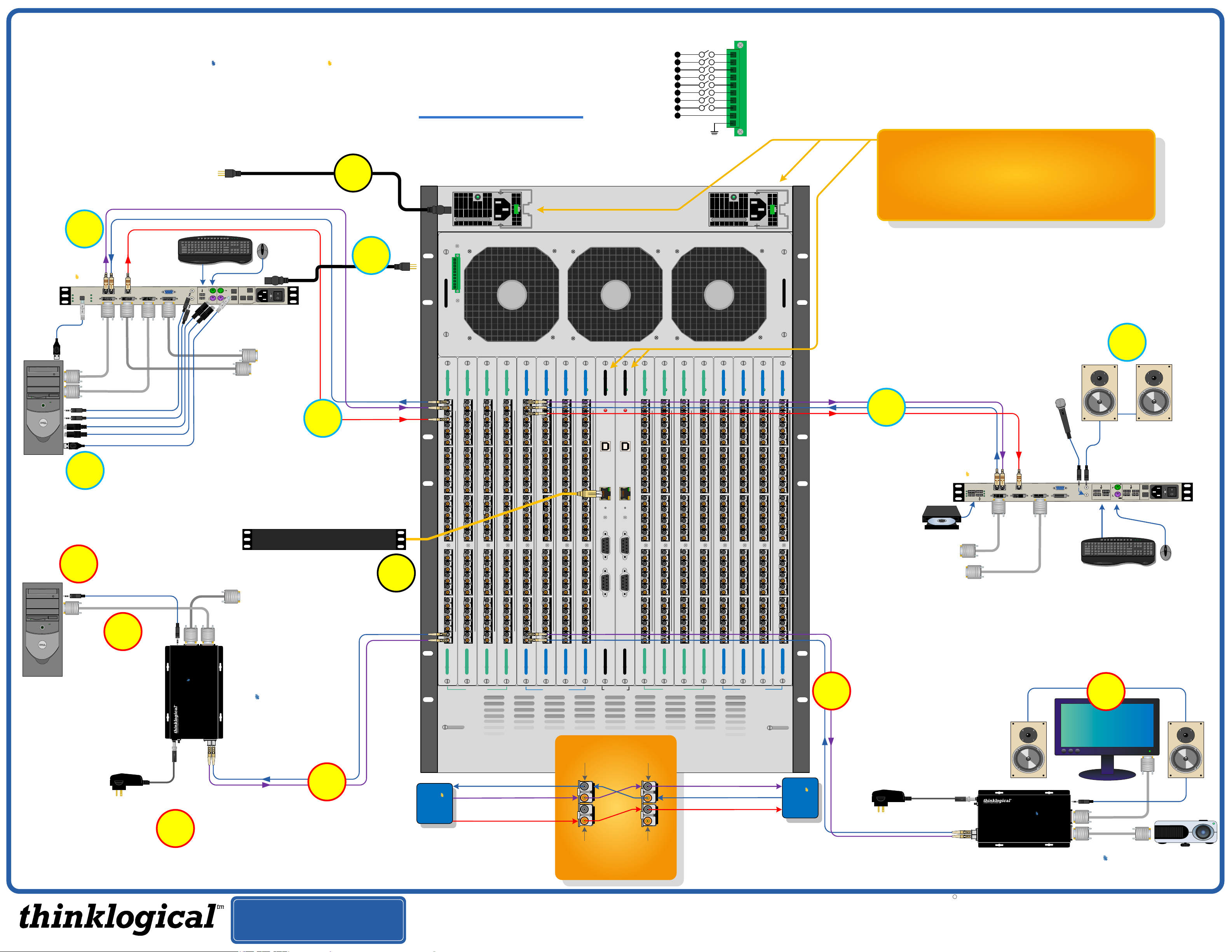
As used with Thinklogical’s™ Velocitydvi-3+ and the Velocitykvm-24
Video Extension Systems
Dual Head DVI & KVM
Source
STEP 5: Connect the DVI IN
cables from the CPU to the
VelocityKVM Transmitter and
the DVI OUT cable(s) from the
transmitter to the local monitor(s).
5
L1
L2
L3
L1: Video 1 and Data Tx to Rx
L2: Data Rx to Tx
L3: Video 2
STEP 8: (Final step) Connect both supplied AC
Power Cords (PWR-0000056-R) to the
receptacles located on the VX160's power
supplies. Plug them to a standard AC source.
Verify that all system functions are operating
properly.
8
Optioal
local USB
or PS/2
Keyboard &
Mouse
4
router
VX160
KVM Matrix Switch
Powered by
MRTS Technology
VX160 Router KVM Matrix Switch Chassis, 16 Rack Units, 850 Watts
12A
100-240V ~ 50/60 Hz
ALARM
10
The VX160 Router Critical Hardware Alarms: (Located at the top, left rear of the unit.)
1
2
3
4
5
6
7
8
9
POWER SUPPLY 1 (LEFT):
POWER SUPPLY 2 (RIGHT):
Individual fan monitoring
FANS:
TEMPERATURE WARNING:
Fan failure, temperature spikes, DC voltage and/or current out of range, AC power input interruption and module removed
Fan failure, temperature spikes, DC voltage and/or current out of range, AC power input interruption and module removed
Chassis over temperature, multiple sensors
TEMPERATURE SHUTDOWN:
Card failure (Only with a redundant card)
CPU:
INPUT/OUTPUT CARDS:
SFP+ failure, laser output fault
ANY OF THE ABOVE
COMMOM
GROUND
12A
100-240V ~ 50/60 Hz
Chassis over temperature causing shutdown
Thinklogical’s™ VX160 KVM Matrix Switch features redundant
Power Supplies and Fail-Over Controller Modules for uninterrupted
performance, even during system reconfiguration, updates or debug.
The VX160 remains fully functional with only one Power Supply
installed or with one Controller activated.
NOTE: When using a single Controller, the module on the left must be used.
Velocitykvm
PWR
FOL
CP
CLINK
L2 L3
L1
DVI IN 1
DVI OUT 1
DVI IN 2
SER IAL PORT
DVI OUT 2
USB
2.0
DVI 1
DVI 2
Audio OUT►
◄Audio IN
PS/2 (Mouse)
PS/2 (Keyboard)
USB 1.1 (Keyboard / Mouse)
STEP 6: Connect your USB, PS/2
and Audio sources to the
6
VelocityKVM Transmitter’s
inputs.
Single Head DVI Source
STEP 6: Connect your Audio source to the
6
Audio OUT 1
DVI
VelocityDVI Transmitter’s input.
5
STEP 5: Connect the
DVI IN cable from the
CPU to the
VelocityDVI
Transmitter and the
DVI OUT cable from
the transmitter to your
local monitor.
LINE IN
HID
MIC OUT
Local DVI
dvi
Transmitter
Velocity
Digital Video Extension System – 3+
L1 L2
P
S
FROM CPU
2
USB HID
LOCAL
Local DVI 2
(optional)
Local DVI 1
(optional)
DVI
Display Display Serial Audio
Powered by
MRTS Technology
▲▼
L1
L2
UPDATES
HOST
USB 1.1
CNTRL
DEV
VEL-U00M24-SCTX
Transmitter
the VelocityKVM
Transmitter’s
ON/OFF switch is
in the OFF (0)
position. Connect
the Power Cord
and plug it into a
standard AC
source. Put the
switch in the ON
(1) position.
3
STEP 3: Connect your VelocityKVM
Transmitter to the VX160 using multi-mode fiber-
optic cables (up to 1000 meters). Connect cable
L1 to any Upstream Receive Port and cable L2 to
the same numbered Upstream Transmit Port.
Connect cable L3 to any other Upstream Receive
Port. (See the Digital Crosspoint Switch detail
diagram, below.)
Linux Operating System
STEP 7: Connect the
Controller Card LAN Port
to your Linux CPU with a
STEP 4: Ensure
7
Velocity
VEL-3+, DVI
Audio, Serial
Transmitter
CAT5 cable.
(IP address: 192.168.13.15)
dvi
L2
L1
L3
1-20 21-40 41-60
POWER
POWER
T
T
20
20
19
18
17
16
15
14
13
12
11
10
9
8
7
6
5
4
3
2
1
I/O BOARD I/O BOARD
R
R
19
18
17
16
15
14
13
12
11
10
9
8
7
6
5
4
3
2
T
T
1
R
R
UPSTREAM
61-80 1-20 21-40 41-60
POWER
POWER
20
19
18
17
16
15
14
13
12
11
10
9
8
7
6
5
4
3
2
1
T
R
T
R
POWER
T
20
19
18
17
16
15
14
13
12
11
10
9
8
7
6
5
4
3
2
1
T
20
R
R
19
18
17
16
15
14
13
12
11
10
9
8
7
6
5
4
3
2
T
T
1
R
R
I/O BOARD I/O BOARDI/O BOARD I/O BOARD
Dual Head or Dual
Link DVI Source
DCS input
POWER
20
19
18
17
16
15
14
13
12
11
10
9
8
7
6
5
4
3
2
1
DOWNSTREAM
61-80
POWER
POWER
T
T
20
20
R
R
19
19
18
18
17
17
16
16
15
15
14
14
13
13
12
12
11
11
10
10
9
9
8
8
7
7
6
6
5
5
4
4
3
3
2
2
T
T
1
1
R
R
I/O BOARD I/O BOARD
SFP+ A
(Video/data IN,
data OUT)
T
R
CONSOLE
T
R
CONTROLLER
ACTIVE
ACTIVE
FAULT
FAULT
USB
USB
LAN
LAN
RESET
RESET
CONSOLE
RS232
RS232
CONTROLLER
CONTROLLER
(Video/data OUT,
81-100 101-120 121-140
POWER
POWER
T
T
20
20
19
18
17
16
15
14
13
12
11
10
9
8
7
6
5
4
3
2
1
I/O BOARD I/O BOARD
R
R
19
18
17
16
15
14
13
12
11
10
9
8
7
6
5
4
3
2
T
T
1
R
R
UPSTREAM
SFP+ A
data IN)
81-100 101-120 121-140
141-160
POWER
20
19
18
17
16
15
14
13
12
11
10
9
8
7
6
5
4
3
2
1
T
R
T
R
POWER
20
19
18
17
16
15
14
13
12
11
10
9
8
7
6
5
4
3
2
1
T
R
T
R
POWER
20
19
18
17
16
15
14
13
12
11
10
9
8
7
6
5
4
3
2
1
I/O BOARD I/O BOARDI/O BOARD I/O BOARD
T
R
T
R
POWER
20
19
18
17
16
15
14
13
12
11
10
9
8
7
6
5
4
3
2
1
Dual Head or Dual
Link DVI Destination
DCS output
POWER
T
20
R
19
18
17
16
15
14
13
12
11
10
9
8
7
6
5
4
3
2
T
1
R
I/O BOARD I/O BOARD
DOWNSTREAM
T
R
T
R
141-160
POWER
20
19
18
17
16
15
14
13
12
11
10
9
8
7
6
5
4
3
2
1
STEP 2: Depending on your configuration, connect your
desktop devices (monitors, keyboard, mouse, etc.) to the
VelocityKVM Receiver using standard cables, as shown
in the examples below. Turn all the devices ON.
Dual Head DVI &
KVM Destinations
2
T
R
1
USB HID
2
AUDIO
P
S
2
U
P
D
HOST
A
T
E
USB 1.1
S
CNTRL
VEL-U00M24-SCRX
Receiver
STEP 1: Connect your
VelocityKVM Receiver to
the VX160 using multi-
L2 L1 L3
mode fiber-optic cables (up
to 1000 meters). Connect
L1 to any Downstream
Transmit Port and L2 to
the same numbered
Velocitykvm
PWR
FOL
USB 2.0
L2
DVI OUT 1 DDC
L1 L3
DVI OUT 1
DVI OUT 2 DDC
SER IAL PORT
DVI OUT 2
LINE OUT
MIC IN
Downstream Receive Port.
Connect L3 to any other
Downstream Transmit
Port. (See the Digital
Crosspoint Switch detail
DVI OUT 1
diagram, below left.)
PS/2 or USB connectors
DVI OUT 2
Monitor, Projector
T
R
and Audio
Destinations
STEP 1: Connect your VelocityDVI
Receiver to the VX160 using multi-
mode fiber-optic cables (up to 1000
1
meters). Connect L1 to any
Downstream Transmit Port and L2
to the same numbered Receive
Port. (See the Digital Crosspoint
Switch detail diagram, left.)
STEP 2: Connect your output devices (monitors,
audio speakers, projector, etc.) to the VelocityDVI
Receiver. Install the Receiver’s 5VDC power
supply and plug it into a standard AC source.
DVI 2
Power Supply
(PWR-000022-R)
STEP 4: Connect the VelocityDVI
Transmitter’s 5VDC Power Supply
and plug it into a standard AC source.
4
3
STEP 3: Connect your VelocityDVI Transmitter
to the VX160 using multi-mode fiber-optic cables
(up to 1000 meters). Connect L1 to any
Upstream Receive Port and L2 to the same
numbered Upstream Transmit Port. (See the
Digital Crosspoint Switch detail diagram, below.)
PHONE: (800) 291-3211
WEBSITE: www.thinklogical.com
EMAIL: support@thinklogical.com
T
R
R
Switch
Fabric
SFP+ B
(Video OUT)
Velocity
Tx
Data Upstream
Video 1 &
Data Downstream
Video 2
SFP+ B
(Video IN)
UPSTREAM DOWNSTREAM
Digital Crosspoint Switch
Visit us online at www.thinklogical.com for more product information, current updates and the complete line of Thinklogical products.
T
Video 1 & Data Downstream
R
Data Upstream
T
Video 2
Velocity
Rx
Power Supply
(PWR-000022-R)
DVI 2 (SECONDARY)
Velocity
dvi
Digital Video Extension System - 3
L2
L1
L2
▲
L1
▼
Receiver
Powered by
MRTS Technology
Display Display Serial Audio
DVI 1 (PRIMARY)
VEL-3+ Single Link DVI, Audio,
Serial Receiver
Velocity
Dual Output
Copyright c 2009. All rights reserved. Printed in the U.S.A. All trademarks and service marks are the property of their respective owners.
TM
AUDIO
dvi
VX160_VEL-3+_VEL-24_Quick_Start_Rev_B
 Loading...