

Page 1
router
The VX160 Router Critical Hardware Alarms: (Located at the top, left rear of the unit.)
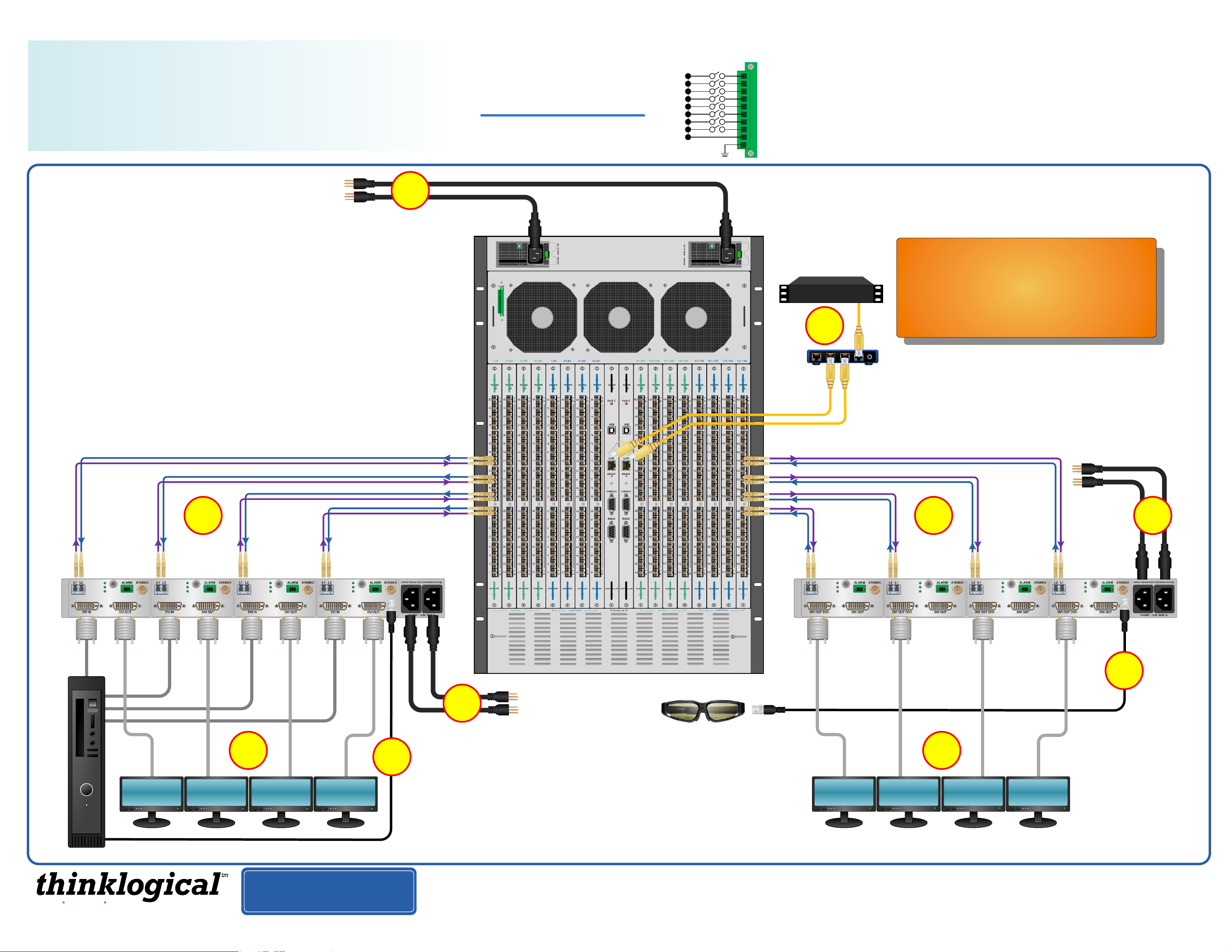
QUICK-START GUIDE
QUICK-START GUIDE
As used with Thinklogical’s™
Q-4300 Video Extension System
Thinklogical’s Q-4300 Chassis can accommodate
four modules in any combination of Transmitter,
Receiver or both. The Q-4300 Chassis will also
accommodate SDIXtreme 3G+ Transmitter and
Receiver Modules. Ask your sales representative
for more information or visit us on the web at
www.thinklogical.com
STEP 9: Connect both supplied AC
Power Cords (PWR-0000056-R) to
the receptacles located on the
VX160's power supplies. Plug each
one into a standard AC source.
Verify that all system functions are
9
operating properly.
VX160
KVM Matrix Switch
Powered by
MRTS Technology
10
1
2
3
4
5
6
7
8
9
POWER SUPPLY 1 (LEFT):
POWER SUPPLY 2 (RIGHT):
Individual fan monitoring
FANS:
TEMPERATURE WARNING:
TEMPERATURE SHUTDOWN:
Card failure (Only with a redundant card)
CPU:
INPUT/OUTPUT CARDS:
ANY OF THE ABOVE
COMMON
GROUND
STEP 8: Connect the Controller
Cards’ LAN Ports to your
Controller CPU with CAT5 cables.
(CPU IP address: 192.168.13.9)
External Control CPU
Fan failure, temperature spikes, DC voltage and/or current out of range, AC power input interruption and module removed
Fan failure, temperature spikes, DC voltage and/or current out of range, AC power input interruption and module removed
Chassis over temperature, multiple sensors
Chassis over temperature causing shutdown
SFP+ failure, laser output fault
Thinklogical’s™ VX160 KVM Matrix Switch features
redundant Power Supplies and Controller Modules for
uninterrupted performance, even during system
reconfiguration, updates or debug. The VX160 remains
fully functional with only one Power Supply installed or with
one Controller activated.
NOTE: When using a single Controller, the module on the
left (Primary) must be used.
8
STEP 4: Connect your Q-4300 Transmitter Modules to the VX160 using multi-mode
fiber-optic cables (up to 1000 meters). Connect L1 to any Receive Port and L2 to the
same numbered Transmit Port. Do the same for each of the four Transmitter modules.
4
L1: Data TX to RX and Video
L2: Data RX to TX
Q-4300: 4 Transmitter Modules
Network
Hub
Primary Controller
Card IP Address:
192.168.13.15
Optional Secondary
Controller Card
IP address: 192.168.13.16
STEP 1: Connect your Q-4300 Receiver
Modules to the VX160 using multi-mode fiber-
optic cables (up to 1000 meters). Connect L1 to
any Transmit Port and L2 to the same numbered
Receive Port. Do the same for each of the four
Receiver modules.
STEP 2: Install the Right Power
Supply Module AC Power Cord
(Left receptacle) and the Left Power
Supply Module AC Power Cord
(Right receptacle). Plug both
Receiver AC Cords into a standard
AC source. On the front of the
chassis, turn ON the Right and Left
Power Supply Modules.
21
Q-4300:
4 Receiver Modules
DVI IN
Module 1
Source CPU
Extend Distribute Innovate
DVI IN
Module 2
Local
DVI OUT
Module 1
Module 3
Local
DVI OUT
Module 2
DVI IN
DVI IN
Module 4
6
Local
DVI OUT
Module 3
PHONE: 1-800-291-3211
WEBSITE: www.thinklogical.com
EMAIL: support@thinklogical.com
Local
DVI OUT
Module 4
7
5
STEP 5: Install the Right Power Supply Module AC Power
Cord (Left receptacle) and the Left Power Supply Module
AC Power Cord (Right receptacle). Plug both Transmitter AC
Cords into a standard AC source. On the front of the chassis,
turn ON the Right and Left Power Supply Modules.
STEP 6: Connect a DVI IN cable from the Source CPU to the
DVI IN ports of each Transmitter Module. If desired, connect
a local monitor to each of the Transmitters’ DVI OUT ports
with a standard DVI cable. Ensure the CPU is turned ON.
Visit us online at www.thinklogical.com for more product information, current updates and the complete line of Thinklogical™ products.
STEP 7: If stereo 3-D molecular
visualization on your desktop is
desired, connect the Stereo OUT
from the CPU to the Transmitter
Module’s STEREO INPUT.
Connect a 3-D Active Stereo
Emitter to the STEREO OUT
receptacle on the Receive module.
DVI OUT DDC
Module 1
DVI OUT DDC
Module 2
Copyright © 2011. All rights reserved. Printed in the U.S.A. All trademarks and service marks are the property of their respective owners.
3
DVI OUT DDC
Module 3
DVI OUT DDC
Module 4
STEP 3: Connect a monitor
to each of the DVI OUT DDC
ports with a standard DVI
cable. A second, non-DDC
monitor may also be
connected to each modules’
DVI OUT port.
7
Q-4300_Single-Link_VX160_Rev_A
 Loading...