

Page 1
The Camera Fiber-Link System uses a Camera Side Unit and a Frame Grabber Side Unit interconnected by duplex, multi-mode fiber optic
cables to allow Camera Link video support up to 500 meters (1640 feet) from the host computer with no loss of signal or resolution and
without the use of amplifiers or repeaters of any kind.
With industrial enhancements such as a threaded screw-lock input power connector and our compact, light-weight design, the Camera FiberLink System is ideal for any application.
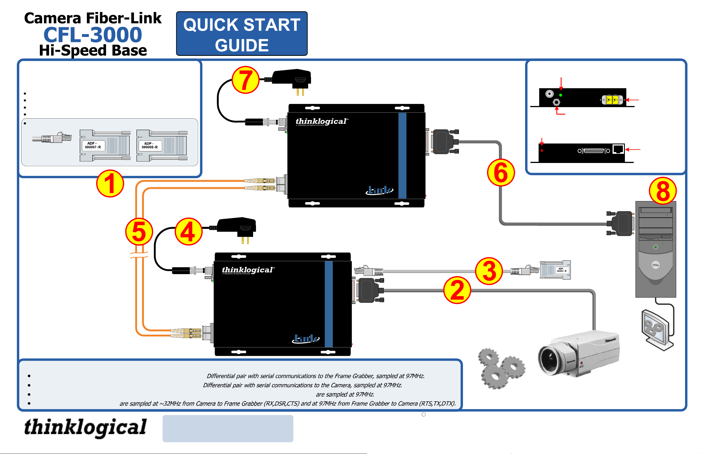
STEP 1: Check the contents.
When you receive your Thinklogical™ CFL-3000 Camera FiberLink system, you should find the following items:
Camera Fiber-Link (CFL-3000 Camera Side) Transmitter
Camera Fiber-Link (CFL-3000 Frame Grabber Side) Receiver
AC Power Supply – Quantity 2
MDR-26 Cable, 2 Meters (CBL-000007-002MR) – Quantity 2
Camera Fiber-Link Adapter/Cable Kit (KIT-000013-R) – Quantity 1
CAT5 cable
3 meters – Qty 2
DB9M to RJ45F DB9F to RJ45F
STEP 5: Install and connect the
standard, multi-mode fiber optic
cables between the Frame Grabber
side unit and the Camera side unit
(up to 500 meters). Be sure not to
kink or pinch the cables and keep all
bend radii to no less than 3 inches.
Multi-Mode Fiber models are
available with SC-, ST-, or LCtype fiber connectors.
Single-Mode Fiber option models
use APC (Angled Physical
Contact) SC-type connectors.
To complement its line of
Camera Fiber-Link extenders,
Thinklogical™ has also
developed high performance
USB 2.0 and Firewire 800
Camera Extenders. Please
contact a Thinklogical™ sales
representative for details.
L1◄
L2►
STEP 7: Connect the standard 5V power supply (PWR-000022-R) to the Frame
Grabber Side Unit (Rx) and plug it into a standard AC source.
CAMERA FIBER-LINK
Digital Camera
Extension System CFL- 3000
HI-SPEED BASE
FRAME GRABBER SIDE
L2◄
L1►
Powered by
MRTS Technology
STEP 4: Connect the standard 5V power supplies
(PWR-000022-R) to the Camera Side Unit (Tx)
and plug it into a standard AC source.
CAMERA FIBER-LINK
Digital Camera
Extension System CFL- 3000
HI-SPEED BASE
CAMERA SIDE
Powered by
MRTS Technology
TM
CAMERA
CAMERA SERIAL
CAMERA
When lit, the green LED
indicates that power is applied.
SERIAL
TM
FRAME
GRABBER
Red LED is ON with no signal and
BLINKS when no camera is connected.
STEP 6: Using the
MDR-26 Cable (CBL000007-002MR),
connect the CPU’s
frame grabber to the
Frame Grabber Side
Unit (Rx).
STEP 3: If using external sensors, lighting, etc., two CAT5 cables
and RJ45 to DB9M and DB9F adapters (KIT-000013-R) are
included to connect your serial device(s) to the Camera Side and
Frame Grabber Side units.
STEP 2: Using the MDR-26 Cable (CBL-000007-002MR), connect the
camera to the Camera Side Unit (Tx) and turn the camera ON.
Fiber-optic cable
ports.
GND
L2
STEP 8: Open your frame grabber
application. Verify that all system
features are functioning properly.
Serial Port
(RJ45) with
RS-232
interface
Camera Fiber-Link Sample Rate:
Communications from Camera to Frame Grabber, SerTFG—
Communications from Frame Grabber to Camera, SerTC—
Camera Control 1 (CC1), Camera Control 2 (CC2), Camera Control 3 (CC3), Camera Control 4 (CC4)
Serial Port Communications
TM
PHONE: (800) 291-3211
WEBSITE: www.thinklogical.com
EMAIL: support@thinklogical.com
Supports all Camera-Link base configurations
with a pixel clock from 20-85MHz.
Copyright c 2009. All rights reserved. Printed in the U.S.A. All trademarks and service marks are the property of their respective owners.
Visit us online at www.thinklogical.com for more product information, current updates and the
complete line of Thinklogical™ products.
Rev B, 6/09
 Loading...