

Page 1
Open platform for Embedded and Real Time Systems Programming
TRI Technosolutions Pvt. Ltd.
T
HINK
LABS
UNI
B
OARD V
Licensed by:
1.1 U
SER GUIDE
4/7/2009
|
Page 2

ThinkLABS
© TRI Technosolutions Pvt Ltd Page 2 of 129 http://thinklabs.in
Table of Contents
Introduction ........................................................................................................................................................ 5
Package Contents ................................................................................................................................................. 6
Testing the Board ................................................................................................................................................. 7
Testing the Board on Windows OS ............................................................................................................................... 7
Testing the Board on Linux OS .................................................................................................................................... 11
What you need for programming the Board ........................................................................................................ 12
Hardware requirements .............................................................................................................................................. 12
Software requirements ............................................................................................................................................... 12
Safety and precautions to be taken ............................................................................................................................ 12
Pre-requisites .............................................................................................................................................................. 12
Hardware Connections ....................................................................................................................................... 13
Features ............................................................................................................................................................ 14
Board Features ............................................................................................................................................................ 14
Controller Features ..................................................................................................................................................... 15
Setting up the Board configuration ..................................................................................................................... 16
Board Description ....................................................................................................................................................... 16
Atmega128 controller ............................................................................................................................................. 16
Atmega8 controller with the firmware for programming through USB ................................................................. 16
I2C and RTC (DS1307) with Backup Battery ............................................................................................................ 16
Analog sensors (Joystick and LDR) .......................................................................................................................... 16
Buzzer ...................................................................................................................................................................... 16
Onboard Motor Driver ............................................................................................................................................ 16
External power ........................................................................................................................................................ 17
Test LEDs ................................................................................................................................................................. 17
Two UART's ............................................................................................................................................................. 17
LCD .......................................................................................................................................................................... 17
Push Buttons ........................................................................................................................................................... 17
Selection Switches................................................................................................................................................... 17
General Purpose PORTS .......................................................................................................................................... 18
Jumper Settings ........................................................................................................................................................... 19
Page 3

ThinkLABS
© TRI Technosolutions Pvt Ltd Page 3 of 129 http://thinklabs.in
Software Installations ........................................................................................................................................ 22
Software Installations for Linux OS ............................................................................................................................. 22
Text Editor (Gedit Editor) ........................................................................................................................................ 22
Installing Gedit Editor: ............................................................................................................................................ 22
Gedit Editor Plug-in (Embedded Terminal): ............................................................................................................ 24
Compiler (avr-gcc) ................................................................................................................................................... 29
avr-libc (Standard C library for Atmel AVR development) : .................................................................................... 31
avrdude (software for programming Atmel AVR microcontrollers): ...................................................................... 33
Serial port terminal (Gtkterm) ................................................................................................................................ 34
Gtkterm Configurations for setting the Baud rate, Parity, Stop bits ...................................................................... 37
Software Installations for Windows OS ...................................................................................................................... 39
WinAVR (Includes avr-gcc, avr-binutils, avrdude) ................................................................................................... 39
Installing USB drivers for uNiBoard ......................................................................................................................... 44
Programming the Board ..................................................................................................................................... 48
Getting Started on Linux ............................................................................................................................................. 48
Getting Started on Windows ...................................................................................................................................... 62
Text Editor (programmer’s Notepad) ..................................................................................................................... 63
Compile the code and program the board on Windows (Command Prompt) ....................................................... 67
Using hyper terminal of windows ........................................................................................................................... 75
Getting Started with RTOS (uC/OS-II) on Windows OS ......................................................................................... 79
uC/OS-II Hardware and Software Architecture .......................................................................................................... 79
Code, Compile and program the RTOS (uC/OS-II) programs on Linux OS .................................................................. 80
Code, Compile and program the RTOS (uC/OS-II) programs on Windows OS ............................................................ 89
Troubleshooting .............................................................................................................................................. 112
Make utility ............................................................................................................................................................... 112
LEDs ........................................................................................................................................................................... 112
UART.......................................................................................................................................................................... 112
LCD ............................................................................................................................................................................ 112
Joystick ...................................................................................................................................................................... 112
LDR ............................................................................................................................................................................ 113
External Interrupts .................................................................................................................................................... 113
RTC ............................................................................................................................................................................ 113
SPI .............................................................................................................................................................................. 113
Page 4
ThinkLABS
© TRI Technosolutions Pvt Ltd Page 4 of 129 http://thinklabs.in
Motor drivers ............................................................................................................................................................ 113
What you can do with the uNiBoard ................................................................................................................. 114
Add-ons ........................................................................................................................................................... 118
SD/MMC card Interface ........................................................................................................................................ 118
Ethernet Interface ................................................................................................................................................. 118
uNiBoard v1.1 Schematic ................................................................................................................................. 119
Controller section: ATmega128 pin connections ...................................................................................................... 119
Buzzer section ........................................................................................................................................................... 120
Joystick and connectors section ............................................................................................................................... 120
LCD section ................................................................................................................................................................ 121
LDR section ................................................................................................................................................................ 121
LEDs section .............................................................................................................................................................. 121
Motor Driver section ................................................................................................................................................. 122
Power supply section ................................................................................................................................................ 122
RTC section ................................................................................................................................................................ 122
Sensor port section ................................................................................................................................................... 123
Switches section ........................................................................................................................................................ 123
UART section ............................................................................................................................................................. 123
USB programmer section (Courtesy: http://www.fischl.de/usbasp/) ...................................................................... 124
Licensing terms ................................................................................................................................................ 125
Bill of Materials (BOM): .................................................................................................................................... 126
Appendix A – References .................................................................................................................................. 128
Appendix B - Services and Support ................................................................................................................... 129
Page 5

ThinkLABS
© TRI Technosolutions Pvt Ltd Page 5 of 129 http://thinklabs.in
Introduction
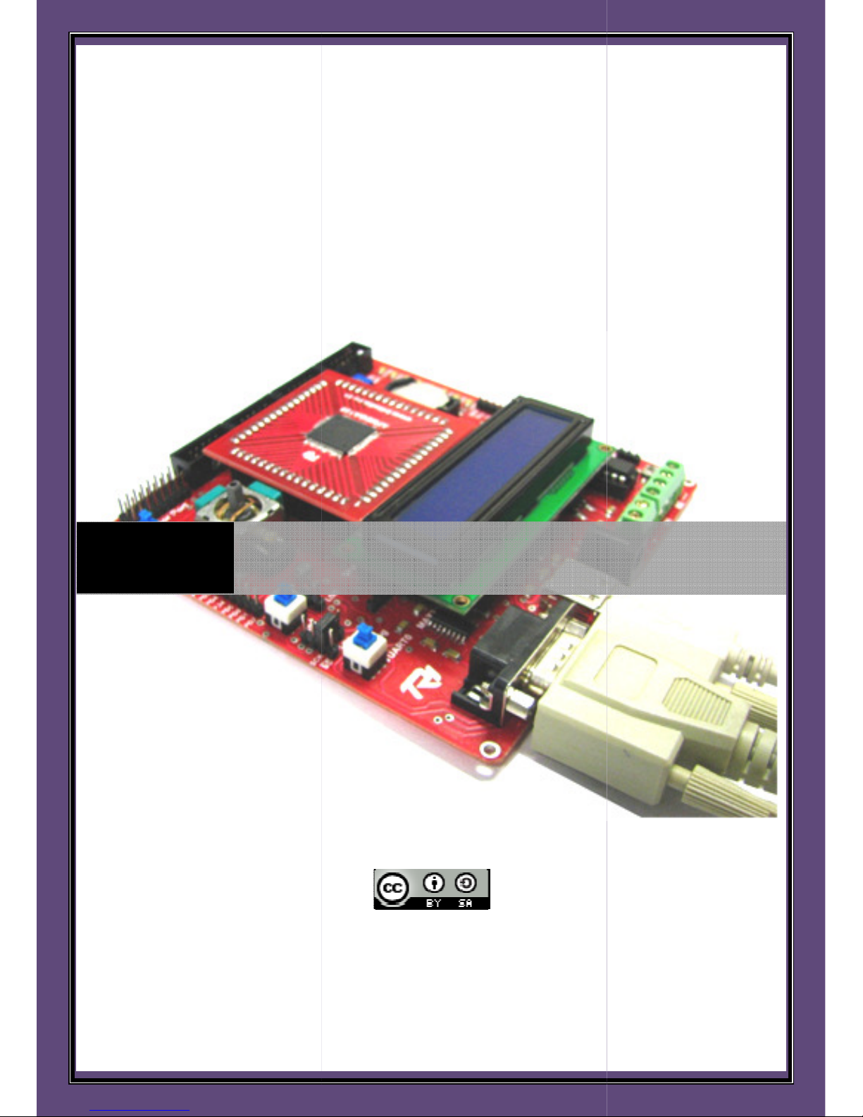
The uNiBoard version 1.1 is an ideal open source development platform for Embedded and Real
Time Systems Programming. Powered by a RISC machine (ATMega128) that provides a throughput
of 16 MIPS and up to 128KB of internal storage (flash), the board would be suitable for any sort of
embedded application development.
On-board peripherals like Joystick along with the communication ports (RS232) and the Gtkterm
driver (hyper-terminal for Windows) make the board apt for basic game development in an
Embedded (non-OS) as well as OS based environment. RT Kernels with small footprint (uC/OS-II,
FreeRTOS, nut OS) can be ported on the board to gain hands-on experience of Real time application
design.
The board is powered by the USB port. The board is also programmable through USB port thereby
making it complete stand-alone lab equipment needing nothing apart from a basic PC/laptop to get
started with the development process. The open interface (open LED interface, open ports) extend
the platform’s role for prototyping applications like external device/sensor interfacing. The
controller by itself supports protocols like SPI, I2C (on-board I2C based RTC), UART (dual
programmable UART) which can be used for multi-board communication.
Additionally, the board also features an on-board motor driver which allows to control up to two
DC motors bidirectionally. External supply, if required for the motors can be provided with
appropriate hardware configuration settings.
The board along with its content-rich user manual is a perfect companion to have for
hobbyists/aspirants seeking a career in Embedded software design, since it can accommodate
preliminary applications like port control or sensor data processing built on Embedded C to
complex real time applications built on RTOS like DAS (Data Acquisition Systems), embedded webserver, FAT FS for embedded systems and more.
We plan to adhere to the Creative Commons license (Refer licensing terms), which has the
philosophy of “Share, Remix, Reuse - Legally”. It means that anyone is allowed to produce copies
of the board, to redesign it, or even to sell boards that copy the design. You don’t need to pay a
license fee to the ThinkLABS team or even ask permission. However, if you republish the reference
design, you have to credit the original group. And if you tweak or change the board, your new
design must use the same or a similar Creative Commons license to ensure that new versions of the
board will be equally free and open.
Page 6

ThinkLABS
© TRI Technosolutions Pvt Ltd Page 6 of 129 http://thinklabs.in
Package Contents
The uNiBoard development platform with the peripherals listed below
• uNiBoard development board – 1 unit
• 16x2 LCD – 1 unit
• Serial cable (DB9) – 1 unit
• USB cable – 1 unit
• FRC connector cables – 2 units
• CD consisting of uNiBoard user manual (based on Linux (Ubuntu) /Windows), essential software
packages and sample codes (RTOS/non-OS applications) – 1 unit
• Pouch for storage – 1 unit
Page 7
ThinkLABS
© TRI Technosolutions Pvt Ltd Page 7 of 129 http://thinklabs.in
Testing the Board
This section lists the procedure to test the board. To enable you to quickly test the Board, it comes with a
test program loaded. So, make sure you first test the board before any programming.
If you have programmed the controller thereby erasing the test program from the flash or in case you find
that the sample program has not been loaded (which would be a rare case) then you need to load the test
program onto the board (refer to the section Programming the Board). The test program is provided on CD
uNiBoard Contents directory (inside sample codes). This code tests the board’s peripherals (LCD, UART,
LED’s, Buzzer, and Joystick).
Testing the Board on Windows OS
Follow the steps to confirm if the uNiBoard is OK.
STEP 1: Connect the LCD on the Board (refer to section Hardware connections).
STEP 2: Use FRC cable to connect open LED port and Port C.
STEP 3: Using the serial cable connect uNiBoard to the PC.
STEP 4: If you are using Windows OS then you need install the USB drivers for the uNiBoard once (refer to
the section Software Installation >> Software Installation for Windows OS >> Installing the USB drivers for
uNiBoard).
STEP 5: Using the USB cable connect the uNiBoard to the PC.
STEP 6: Turn ON the Board once the drivers are installed correctly.
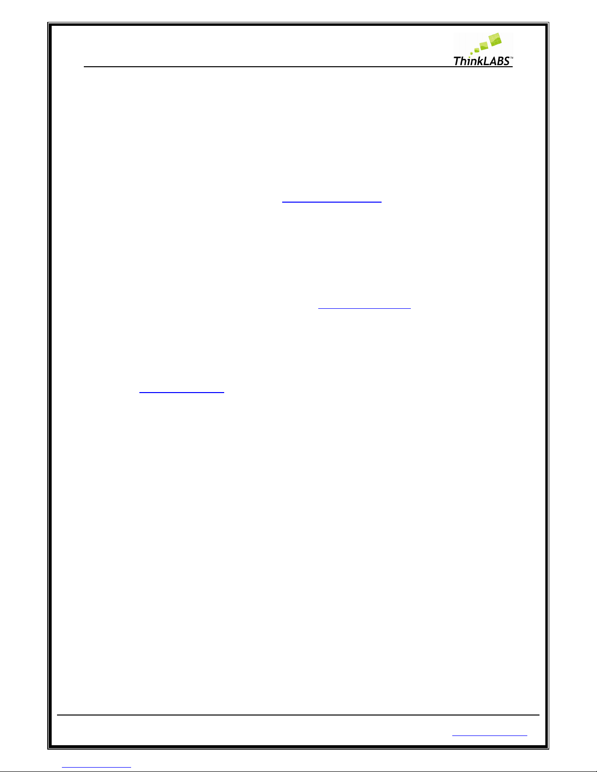
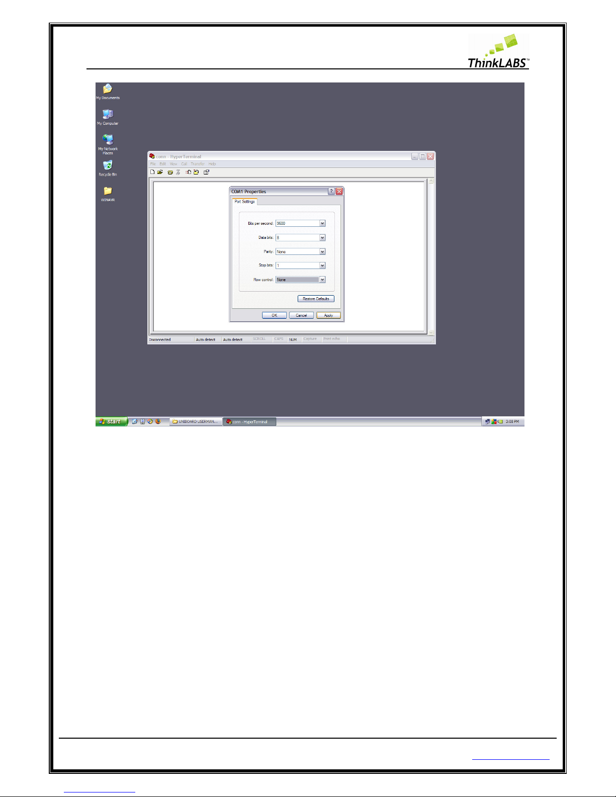
STEP 7: Open the Serial terminal and set the baud rate to 115200, parity to none, and stop bits to 1. So click
on Start >> programs >> Programs >> Accessories >> Communications >> hyper terminal as shown below.
Page 8
ThinkLABS
© TRI Technosolutions Pvt Ltd Page 8 of 129 http://thinklabs.in
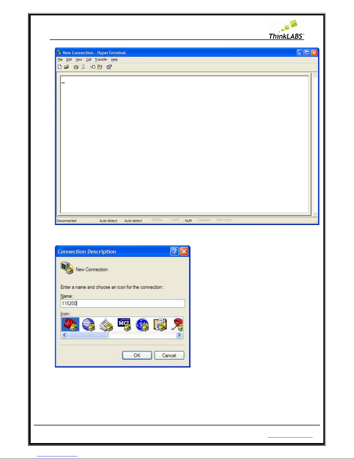
STEP 8: Select File menu >> New Connection then Enter Name for connection and click OK.
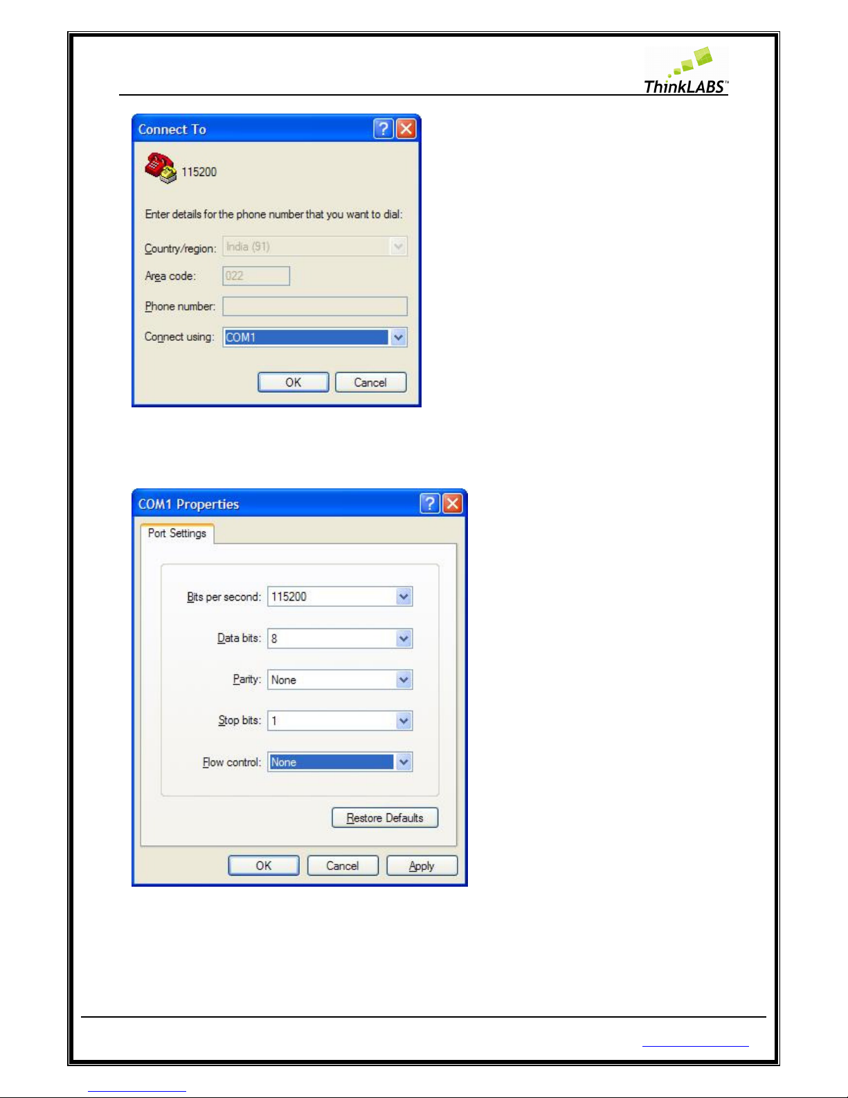
STEP 9: Select the COM Port where you have connected the serial cable.
Page 9
ThinkLABS
© TRI Technosolutions Pvt Ltd Page 9 of 129 http://thinklabs.in
STEP 10: Select the settings as given below for this test program.
STEP 11: Select Apply and then OK.
Page 10
ThinkLABS
© TRI Technosolutions Pvt Ltd Page 10 of 129 http://thinklabs.in
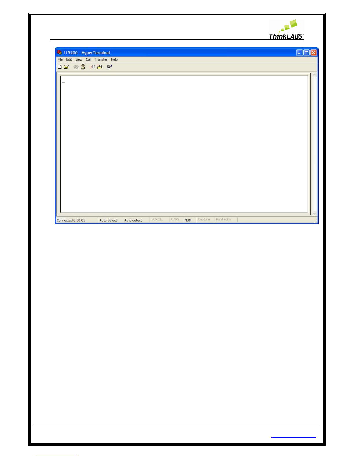
STEP 12: Turn ON the Board.
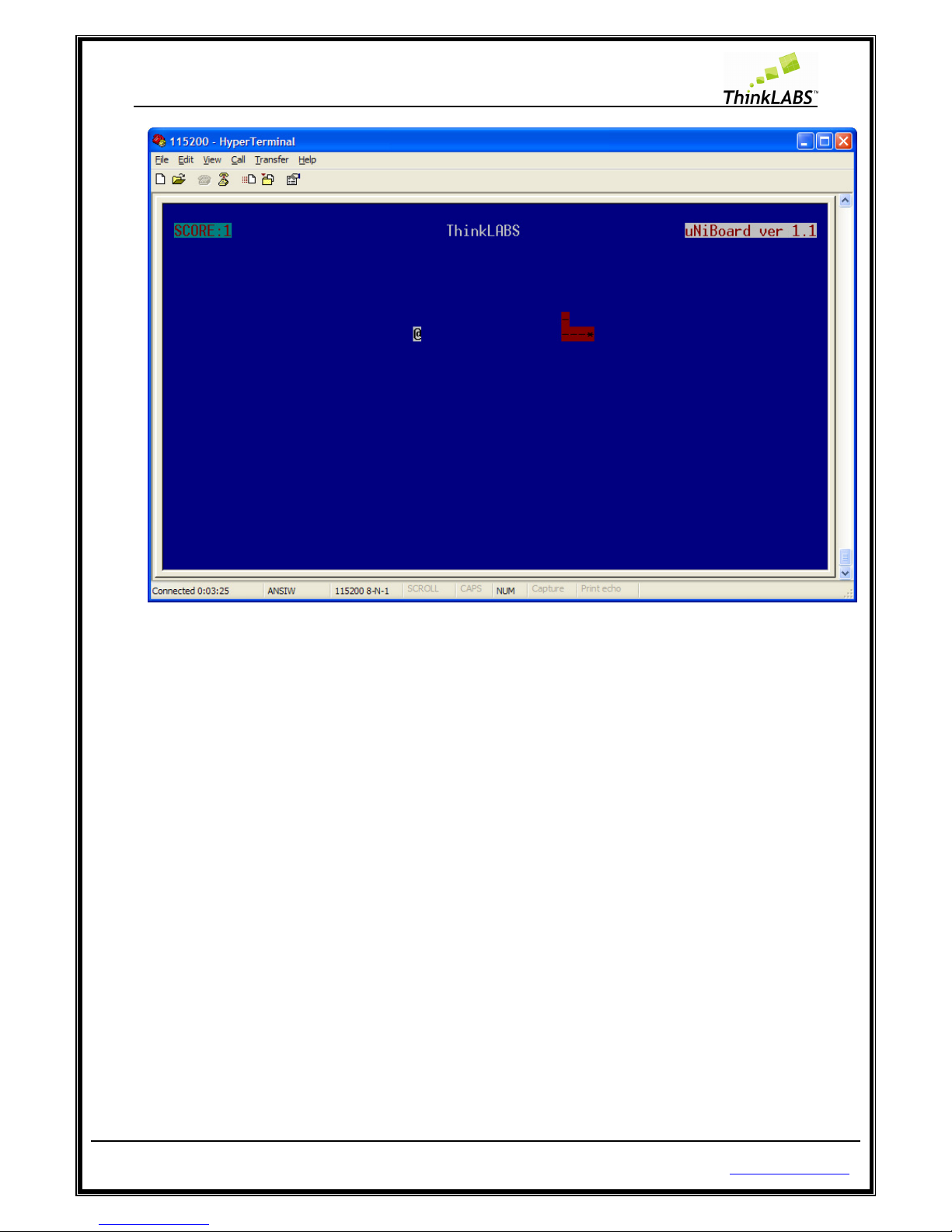
STEP 13: The test program that we have loaded demonstrates SNAKE game on any serial terminal which is
VT102 compatible. If everything is correctly installed you should be able to see a game of SNAKE (modified)
as well as play using the Joystick.
While the program is running you will also be able to see the SCORE being displayed on the LCD along with
the version of the uNiBoard that you are currently using. While the SNAKE eats up food you will be able to
hear the buzzer. Every time a new food is generated you will see the LEDs glowing thereby utilizing all
uNiBoard peripherals.
Page 11
ThinkLABS
© TRI Technosolutions Pvt Ltd Page 11 of 129 http://thinklabs.in
Testing the Board on Linux OS
Follow the steps to check whether or not the uNiBoard is working properly on Linux OS
STEP 1: Step 1 to Step 3 is same as given in the Windows OS procedure.
STEP 2: Turn ON the Board. If you are wondering how to install the USB drivers, you don’t need to do that at
all since Linux kernel has those drivers inbuilt.
STEP 3: Open the Gtkterm (refer to the sub-section Installing Software for Linux OS).
STEP 4: Configure the Gtkterm to baud rate/speed to 115200, parity to none, and stop bits to 1(refer to the
sub-section Gtkterm Configurations for setting the Baud rate, Parity, Stop bits).
STEP 5: Turn ON the Board.
STEP 6: Out here as well you should be able to do things (like playing SNAKE on Gtkterm) that have been
listed in STEP 13.
Page 12

ThinkLABS
© TRI Technosolutions Pvt Ltd Page 12 of 129 http://thinklabs.in
What you need for programming the Board
Hardware requirements
• uNiBoard version 1.1 along with USB cable
• Serial cable (optional)
• FRC Cable (optional)
Software requirements
• Text Editor (Gedit on Linux/ Programmers Notepad on Windows)
• Tool chain (avr-gcc, avr-binutils, avrdude): Installation procedure is explained in the upcoming
sections
• Serial terminal (Gtkterm on Linux/ hyper terminal on windows)
• Driver for usbasp (Windows requires explicit installation)
Safety and precautions to be taken
• Do not use the external power supply more than 15V.
• Board and SMD switches should be handled with care.
• Fuse settings of the target (micro-controller) should be modified only with appropriate
knowledge, since locking the fuse section might render the board useless.
• Do not program the Board while you are using SPI lines for communication which might also
render the board useless.
Pre-requisites
• Before you start, you are expected to have some knowledge of AVR microcontrollers and its
software tools up to a preliminary level. We have not discussed the AVR architecture (Datasheet
is the best help on the same. it has been included in the CD contents)
• The board guide does not give any conceptual knowledge with regards to RTOS. For best results,
you are expected to have a reference material on the RTOS that you are going to use on the
board. In case the target RTOS is uC/OS-II, you need not look beyond MicroC/OS-II, The Real
Time Kernel by Mr. Jean Labrosse.
• All the samples examples based on RTOS including the SNAKE application that you must have
just seen while testing the board utilize the same RTOS kernel (i.e.: uC/OS-II)
Page 13

ThinkLABS
© TRI Technosolutions Pvt Ltd Page 13 of 129 http://thinklabs.in
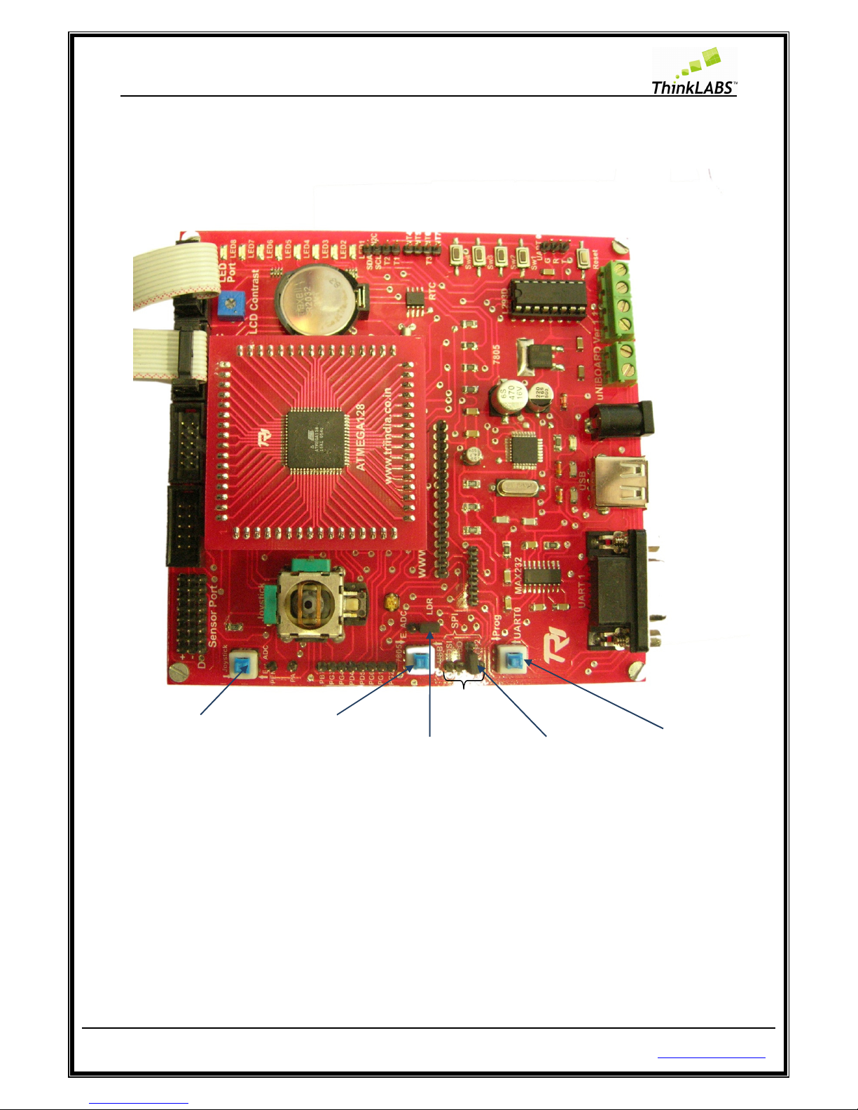
Hardware Connections
The uNiBoard version 1.1 connects to the PC using USB port. As shown in the figure 1.1 on the board there is
a serial port and USB port connectors. The serial port is used for debugging purpose while USB port is used
for power and burning the hex files into ATmega128 microcontroller.
The USB cable (for power/programming purposes) and serial cable can be interfaced with the PC. The serial
cable is optional as we are not using it for programming the hex file into the Atmega128 chip. For any UART
related activities having the serial cable is a must.
Progr
amming
Jumper
Programming
connector for
USB
programmer
LDR
Jumper
8 Sensor
inputs
Program
Enable/UART0
Selection
USB power
switch
Test
LEDs
PORT
Ext Power
Connector
UART 0
USB
Port
Serial Port
(UART 1)
Motor 1
Motor 2
Joystick/Ext. ADC
switch
Reset switch
ADC
PORT
JTAG
PORT
PORTC
USB
programmer
FRC
Cable
LDR
RTC
RTC Backup
battery
LCD
connector
Joystick
PORTG
connector
8 LED’s
SW4, SW3,
SW2, SW1
switch i/p’s
4 SPI
Lines
Buzzer
beneath
Controller
8 GND
lines
8 VCC
lines
Page 14

ThinkLABS
© TRI Technosolutions Pvt Ltd Page 14 of 129 http://thinklabs.in
Features
Board Features
• ATmega128 controller with external crystal of 16MHZ
• usbasp: ATmega8 based USB programmer for ATmega128 (open source firmware running on
hardware licensed under GNU GPLv2 from http://www.fischl.de/usbasp)
• I2C communication lines
• SPI communication lines
• 16x2 alphanumeric LCD with contrast adjustment
• RTC with Backup Battery
• Analog Joystick with centre click
• LDR sensor
• Buzzer (beneath the processor board)
• Onboard Motor Driver (L293D)
• LEDs for USB programmer ready indicator, Programming status indicator, and Power ON
indicator
• Test LEDs (open for interface with any PORT)
• Open interface Ports such as PORTF/ADC, PORTC
• JTAG interface(External JTAG hardware required)
• USB Port for programming the Board
• Dual programmable UARTs
• Push Buttons for External Interrupts, Reset
• Configuration Switches for USB Power/External power, External ADC /Joystick and Program
Enable/UART0
• Modular design to permit replacement of processor board
Page 15

ThinkLABS
© TRI Technosolutions Pvt Ltd Page 15 of 129 http://thinklabs.in
Controller Features
The features of Atmega128 are as follows:
• Advanced RISC Architecture
• 128K Bytes of In-System Self-programmable Flash program memory
• 4K Bytes EEPROM
• 4K Bytes Internal SRAM
• JTAG (IEEE std. 1149.1 Compliant) Interface
• Two 8-bit Timer/Counters with Separate pre-scaler and Compare Modes
• Two Expanded 16-bit Timer/Counters with Separate pre-scaler, Compare Mode and
• Capture Mode
• Real Time Counter with Separate Oscillator
• Two 8-bit PWM Channels
• 6 PWM Channels with Programmable Resolution from 2 to 16 Bits
• 8-channel, 10-bit ADC
• Byte-oriented Two-wire Serial Interface
• Dual Programmable Serial USARTs
• Master/Slave SPI Serial Interface
• Programmable Watchdog Timer with On-chip Oscillator
• Power-on Reset and Programmable Brown-out Detection
• External and Internal Interrupt Sources
• Six Sleep Modes: Idle, ADC Noise Reduction, Power-save, Power-down, Standby, and Extended
Standby
• Software Selectable Clock Frequency (using Fuse bits)
• 53 Programmable I/O Lines
• 4.5V - 5.5V for Atmega128 Operating Voltages
• 64-lead TQFP
Page 16
ThinkLABS
© TRI Technosolutions Pvt Ltd Page 16 of 129 http://thinklabs.in
Setting up the Board configuration
Board Description
Atmega128 controller
The ATmega128 is a low-power 8-bit microcontroller based on the AVR enhanced RISC architecture. The
Atmel ATmega128 is a powerful microcontroller that provides a highly flexible and cost effective solution to
many embedded control applications.
Atmega8 controller with the firmware for programming through USB
USBasp is a USB in-circuit programmer for Atmel AVR controllers. It simply consists of an ATMega8 and a
couple of passive components. The programmer uses a firmware (USB driver) to program Atmega128
microcontroller. For more information on building USBasp refer http://www.fischl.de/usbasp. It is an open
source firmware along with hardware licensed under GNU GPLv2.
I2C and RTC (DS1307) with Backup Battery
The DS1307 serial real-time clock (RTC) is a low-power, full binary-coded decimal (BCD) clock/calendar plus
56 bytes of NV SRAM. Address and data are transferred serially through an I2C, bidirectional bus. The
clock/calendar provides seconds, minutes, hours, day, date, month, and year information (Compensation
Valid up to 2100). No special hardware configuration is required as it is mounted on our board and internally
connected to the processors pins.
Analog sensors (Joystick and LDR)
The Joystick (Analog joystick used in PS2 consoles) is connected to the ADC, X axis on channel 1 (PF1) and Y
axis on channel 2 (PF2) of the Atmega128 microcontroller. The LDR sensor is connected to channel 0(PF0) of
the Atmega128 microcontroller.
Buzzer
The Buzzer is connected to PA3 of the Atmega128 microcontroller, and lies beneath the processor board.
Onboard Motor Driver
The Motor driver chip (L293D) is used to drive the motors which can be connected to the PTR connectors as
shown in the above figure. Through software you need to configure as follows:
PB6 and PB5 (MOTOR1)
PE2 and PE3 (MOTOR2)
PB4 (CHIP ENABLE)
There are motors which might need higher than 5V (up to 12V) operating voltage. In such cases an external
supply can be given to the board and the USB power switch can be toggled to make the external supply
available instead of a USB powered connection.
Page 17
ThinkLABS
© TRI Technosolutions Pvt Ltd Page 17 of 129 http://thinklabs.in
External power
The external power connector in the above figure can also be used for connecting rechargeable batteries
and making the board operate on battery power in case of robotic or other such mobile applications.
Test LEDs
Test LED's are pulled-up so to glow the LEDs we need to make the particular port pin Low. You can connect
the General Purpose PORT to test LED Port using FRC Cable.
Two UART's
UART1 is used to connect PC through the MAX232 voltage converter chip since pc uses RS-232 standard for
serial port. UART1 can be used for debugging the code or for any sort of interaction with Gtkterm.
UART0 is not connected to MAX232 as it is left open for communication between two Boards.
LCD
LCD for uNiBoard is using 4 data lines, 2 control lines and WR of LCD is connected to GND.
DATA LINES (PA4, PA5, PA6, PA7)
CONTROL LINES (PA0 for RS, PA2 for LCD EN)
Push Buttons
External Interrupts
SW3 (INT6)
SW4 (INT7)
General Purpose switch
SW1 (PD6) Active Low
SW2 (PD7) Active Low
Reset SW
Selection Switches
USB Power (Pressed) / External power (Depressed)
Joystick (Pressed) / External ADC (Depressed)
Program Enable (Pressed) / UART0 (Depressed)
The most important part of board configuration is the configuration switches. More often than not,
programming errors or abnormal program response and execution are due to faulty configuration of
the switches. So, while programming, or using ADC, or external power supply or battery or while using
UART0 make sure you have first set the configuration switches in the correct position before
concluding that your program is not working or the board is faulty.
Page 18
ThinkLABS
© TRI Technosolutions Pvt Ltd Page 18 of 129 http://thinklabs.in
USB Power (Pressed) / External power (Depressed)
Refer to the uNiBoard figure where the components have been labeled to understand where these
switches are physically placed on the board. While you have connected the uNiBoard cable for
programming purposes or for powering the board this switch should be in the pressed position.
While connecting any external power supply or battery, this switch should be in depressed position.
This makes the 7805 voltage regulator come into picture to provide 5V power supply for the ICs.
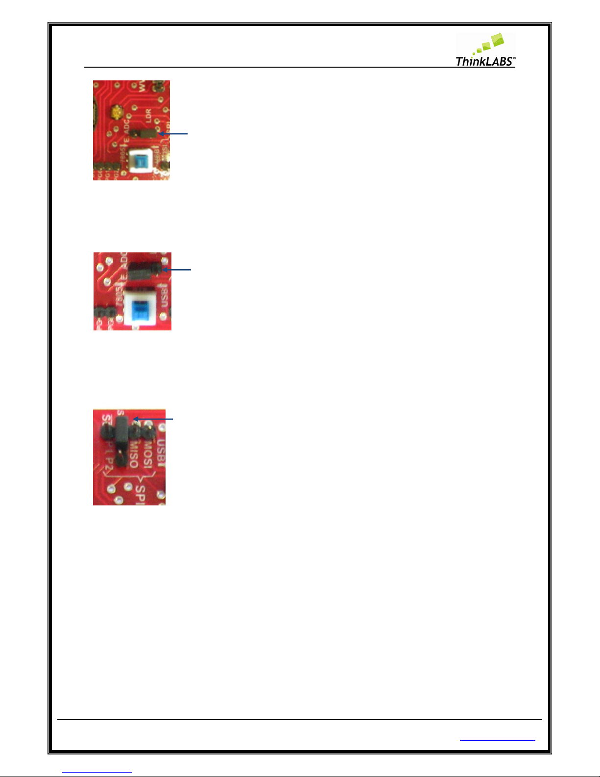
Joystick (Pressed) / External ADC (Depressed)
While you are using the analog joystick you are using the internal ADC of the controller which is
available at PORTF (Channel 1 – X axis and Channel 2 – Y axis). The LDR which is another analog
sensor is also connected at PORTF (Channel 0). Make sure that this switch is in pressed position
while the joystick is being used.
In case you want to use the open interface pins of the PORTF, in order to connect external analog
sensors or digital sensors (refer labeled figure of uNiBoard), change the switch position to
depressed. There is another jumper setting which you would need to do in order to take the LDR out
of the circuit. This configuration will be discussed while discussing jumper settings.
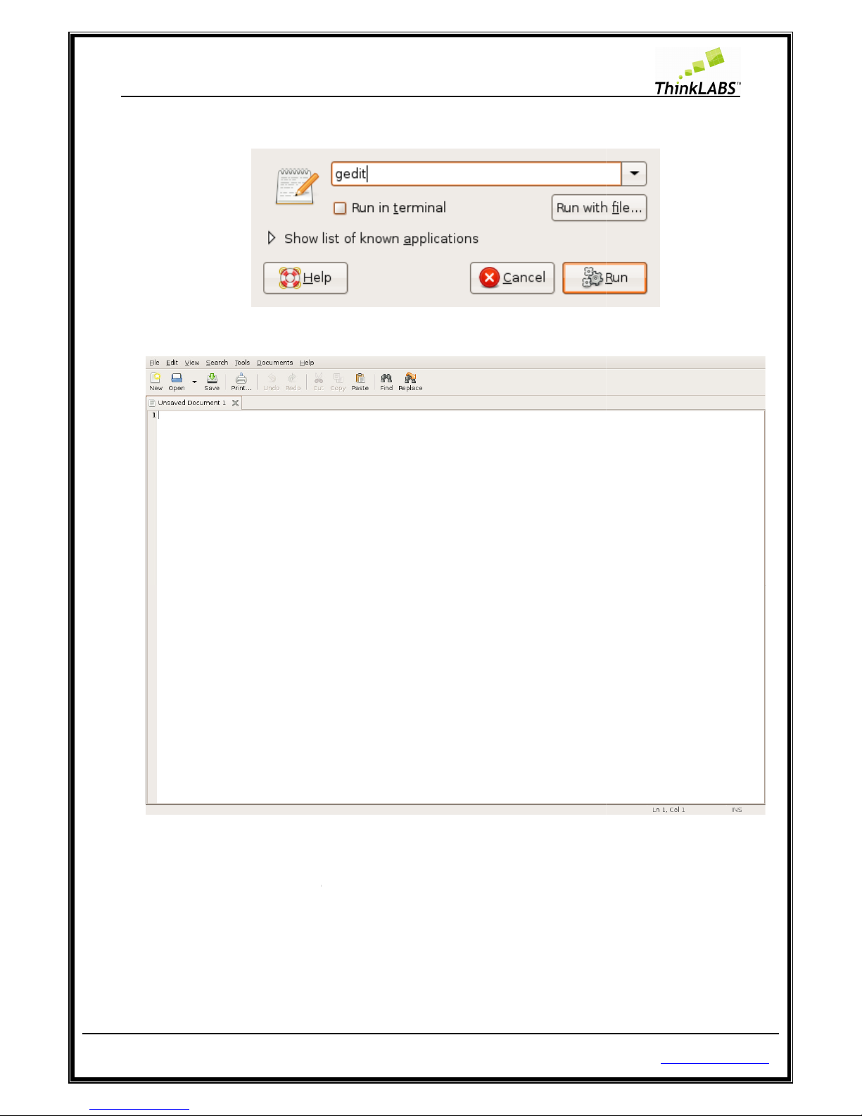
Program Enable (Pressed) / UART0 (Depressed)
While programming the board this is one switch that you should never forget to press, failing which
avrdude (programming software will flash an error saying “target not found”.
Once programming has been completed in order to gain access to UART0 you will need to keep the
switch in the depressed position, since the UART0 pins are multiplexed with the programming pins.
General Purpose PORTS
PORTC
PORTC is an open interface port which can be used to connect any devices on FRC connector.
PORTF (Joystick/LDR/External sensors)
PORTF can be used to connect external analog or digital sensors or it can also be used as Joystick or LDR ADC
channels. There are two connectors FRC connector and Berg sensor port connector either of which can be
used to connect the external sensors. The Berg sensor port connector is compatible with our TRI sensors.
You can visit to website at http://www.thinklabs.in/resources/ to checkout TRI sensors and you can buy at
http://www.thinklabs.in/shop/.
PORTG
PORTG is an open interface port which can be used to connect any devices on berg connector.
PORTC and PORT F
Page 19
ThinkLABS
© TRI Technosolutions Pvt Ltd Page 19 of 129 http://thinklabs.in
The PORTC and PORTF (ADC) are open ports and can be connected to test LEDs through FRC cable. These can
be accessed using 10-pin the FRC connector.
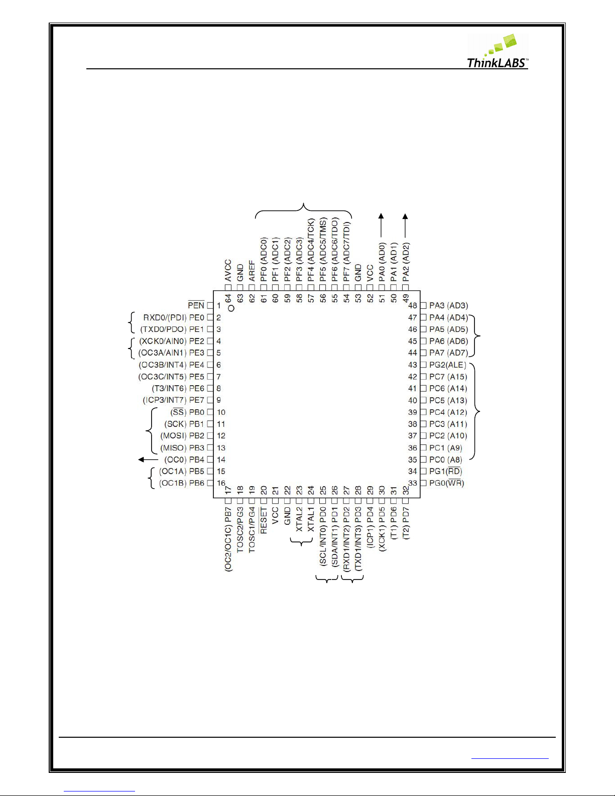
The pin diagram of Atmega128 is given below along with the manner in which we have utilized the port pins
in case of uNiBoard:
Jumper Settings
Apart from the configuration switches discussed above the jumper settings is another source of arriving to
wrong conclusions provided that they have not been set correctly.
SPI
lines
LCD
DATA
UART0
I2C
(RTC)
PORTC
(Open
Interface on
FRC
connector)
UART1
(Max232)
16 MHz
Crystal
MOTOR 2
MOTOR 1
MOTOR EN
Joystick/LDR/Ex
ternal sensors
LCD RS
LCD EN
Page 20
ThinkLABS
© TRI Technosolutions Pvt Ltd Page 20 of 129 http://thinklabs.in
There are two jumpers on the board one for programming or SPI jumper and other one for LDR or External
ADC selection. As shown in the figure below:
LDR jumper
You can use them as per your application requirements. In case you are connecting external sensors at the
sensor port, you will need to change the position of the LDR jumper so as to disassociate it from the circuit
as shown below:
LDR
Jumper
4 SPI
Lines
Programming
Jumper
Joystick/External
sensor Selection
USB Power
Selection
Program Enable
/UART0 Selection
Page 21
ThinkLABS
© TRI Technosolutions Pvt Ltd Page 21 of 129 http://thinklabs.in
While connecting external sensors at the open interface of PORTF, this jumper position should be changed to
the alternate position as shown below:
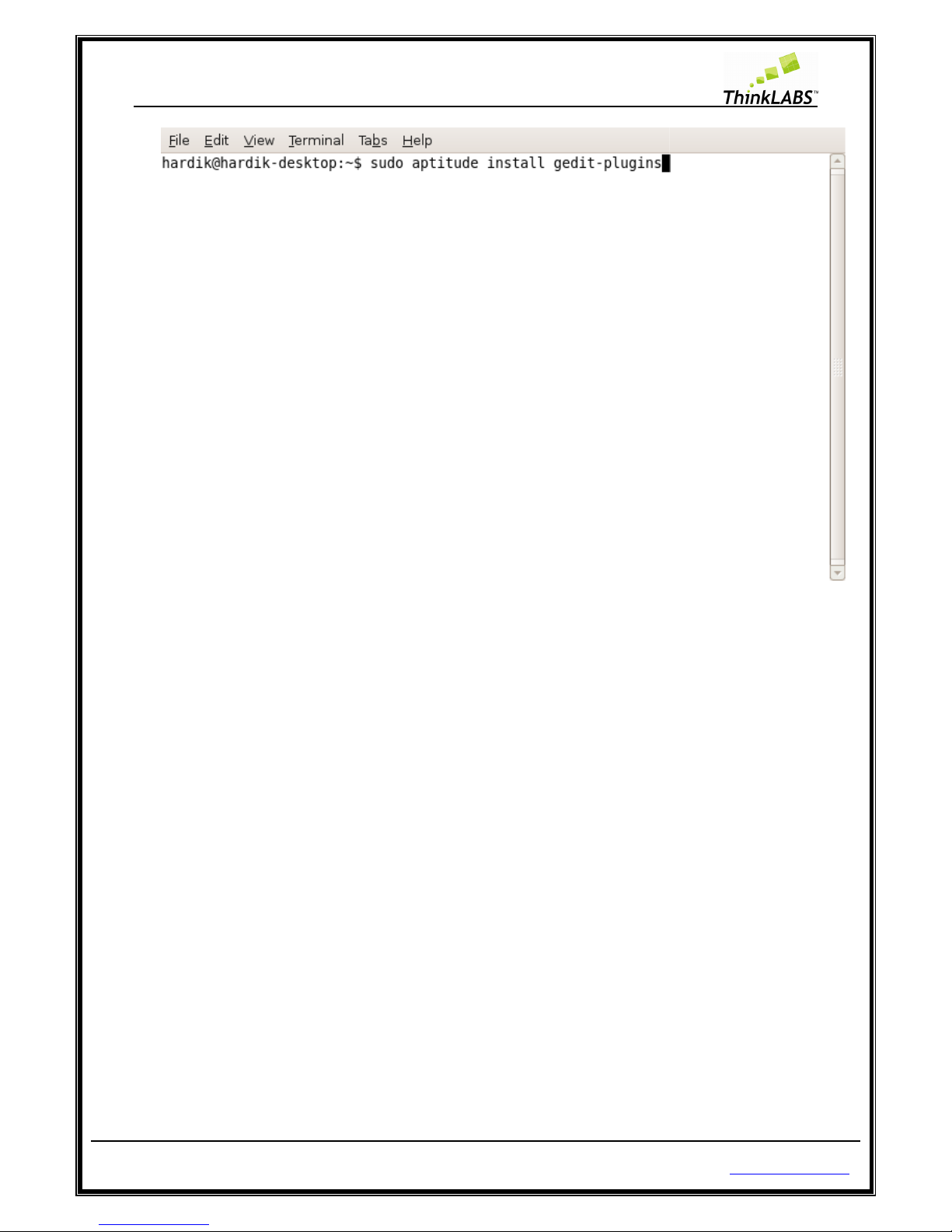
Programming jumper:
The programming jumper has to be retained in the position shown below under all cases except when using
the SPI communication lines.
While using the SPI communication lines the jumper can be either removed or placed in the adjoining pins
provided which is NC (No Connection), as shown below. The latter is a safer option to ensure that you do not
misplace the jumper.
Position of jumper while using LDR senso
r
Position of jumper using external analog
sensors
Position of jumper while using LDR sensor
Page 22

ThinkLABS
© TRI Technosolutions Pvt Ltd
Software Installation
Software Installation
s for Linux OS
The procedure that we are discussing for U
manager. Hence you need to have an internet connection in place before you begin with this.
of *.deb or *.rpm packages of the listed software and install it on your system.
The
following section describes t
Text Editor
(Gedit Editor)
The Gedit (text editor) might be installed already on your system, since it’s the default text editor provided
by the distribution. If you fin
d that it is missing you can follow the below mentioned steps.
Installing Gedit Editor:
STEP 1:
Open terminal and type: “sudo aptitude install gedit” and press enter
Page 22 of 129
s
buntu
Linux involves downloading packages through the synaptic
he installation of the software packages
on Ubuntu Linux
http://thinklabs.in
If not get hold
.
Page 23

ThinkLABS
© TRI Technosolutions Pvt Ltd
STEP 2: Enter root password.
STEP 3:
It will show a list of all dependencies
Page 23 of 129
installed as shown below
http://thinklabs.in
Page 24
ThinkLABS
© TRI Technosolutions Pvt Ltd
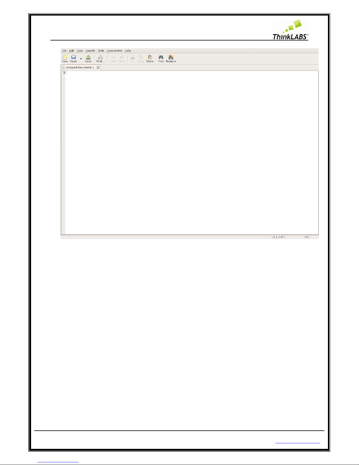
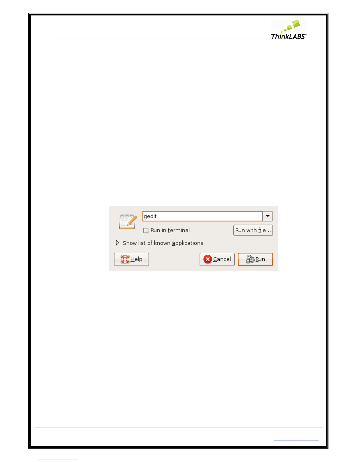
STEP 4:
Press ALT + F2 and type gedit and press enter to open the Gedit application
STEP 5:
The Gedit application will open
Gedit Editor Plug-in
(Embedded Terminal):
The Embedded Terminal is
a gedit
execute Linux commands, compile program using the MAKE utility and download it on to our chip
NOTE:
Close all gedit application.
STEP 1:
Open terminal and type: “sudo aptitude install gedit
Page 24 of 129
plug-in which fits a terminal in
the gedit window through whic
-
plugins” and press en
http://thinklabs.in
h we can
ter
Page 25
ThinkLABS
© TRI Technosolutions Pvt Ltd
STEP 2: Enter root password.
STEP 3:
It will show a list of all dependencies installed as shown below
Page 25 of 129
http://thinklabs.in
Page 26

ThinkLABS
© TRI Technosolutions Pvt Ltd
STEP 4:
Press ALT + F2 and type gedit and press enter to open the Gedit application
STEP 5:
The Gedit application will open
Page 26 of 129
.
http://thinklabs.in
Page 27
ThinkLABS
© TRI Technosolutions Pvt Ltd
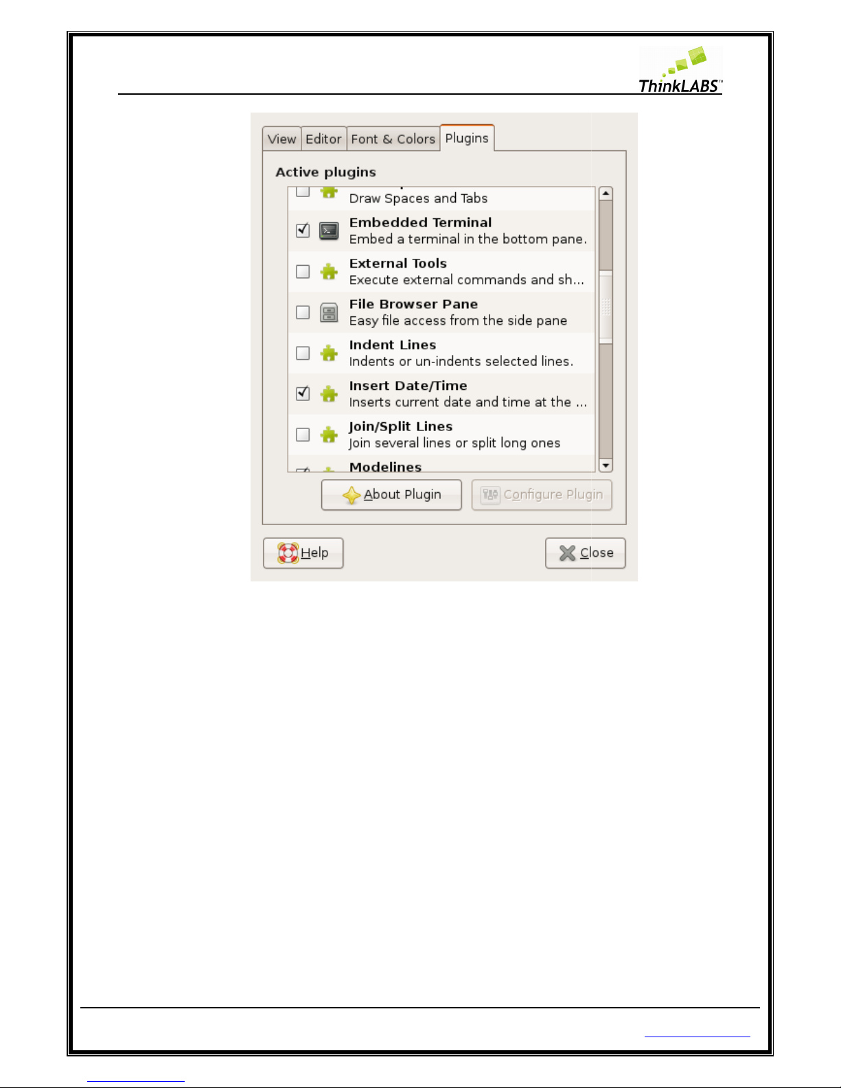
STEP 6:
Then in gedit open Edit menu > preferences and goto plugins tab
STEP 7:
Select Embedded Terminal and press close button
Page 27 of 129
.
http://thinklabs.in
Page 28
ThinkLABS
© TRI Technosolutions Pvt Ltd
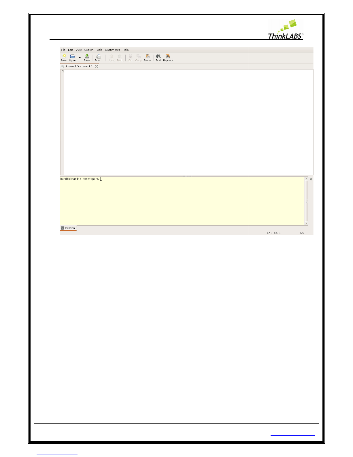
STEP 8:
Go to the View menu and select Bottom pane
Page 28 of 129
http://thinklabs.in
Page 29
ThinkLABS
© TRI Technosolutions Pvt Ltd
Compiler (avr-gcc)
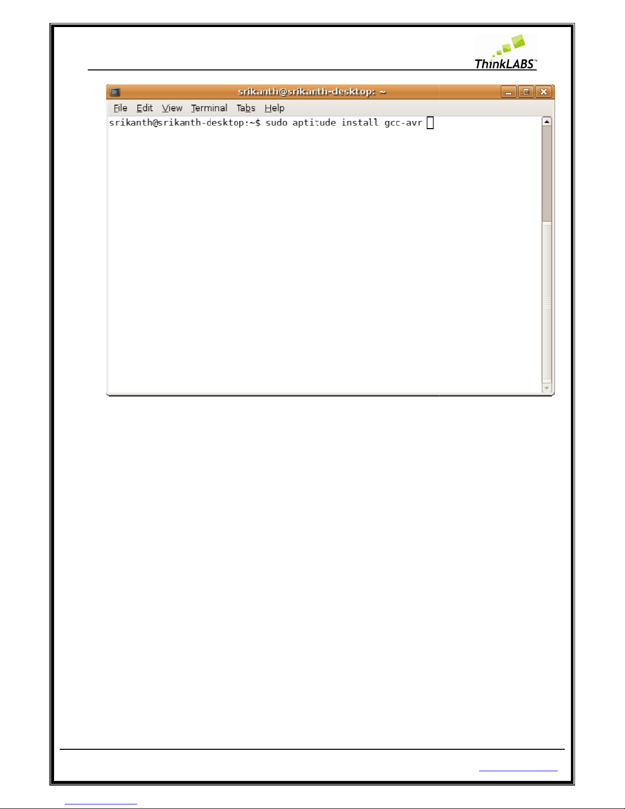
STEP 1:
Open terminal and type: “sudo aptitude install
Page 29 of 129
gcc-avr” and press enter
http://thinklabs.in
Page 30
ThinkLABS
© TRI Technosolutions Pvt Ltd
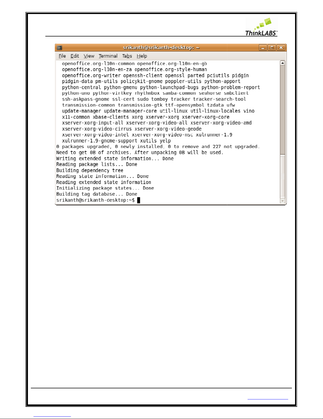
STEP 2: Enter root password.
STEP 3:
It will show a list of all dependencies install as shown below
Page 30 of 129
.
http://thinklabs.in
Page 31
ThinkLABS
© TRI Technosolutions Pvt Ltd
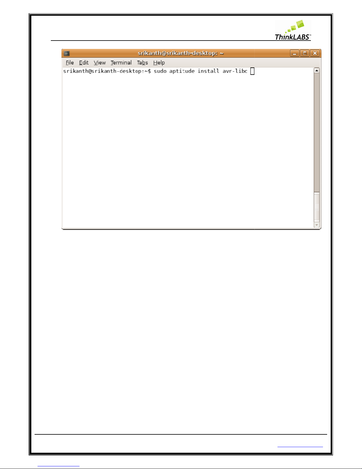
avr-
libc (Standard C library for Atmel AVR development) :
STEP 1:
Open terminal and type: “sudo aptitude install avr
Page 31 of 129
-libc” and press enter
http://thinklabs.in
Page 32
ThinkLABS
© TRI Technosolutions Pvt Ltd
STEP 2: Enter root password
STEP 3:
It will show a list of all dependencies install as shown below
Page 32 of 129
http://thinklabs.in
Page 33

ThinkLABS
© TRI Technosolutions Pvt Ltd
avrdude
(software for programming Atmel AVR microcontrollers):
STEP 1:
Open terminal and type: “sudo aptitude install avrdude” and press
Page 33 of 129
enter
http://thinklabs.in
Page 34

ThinkLABS
© TRI Technosolutions Pvt Ltd
STEP 2: Enter root password
STEP 3:
It will show a list of all dependencies install as shown below
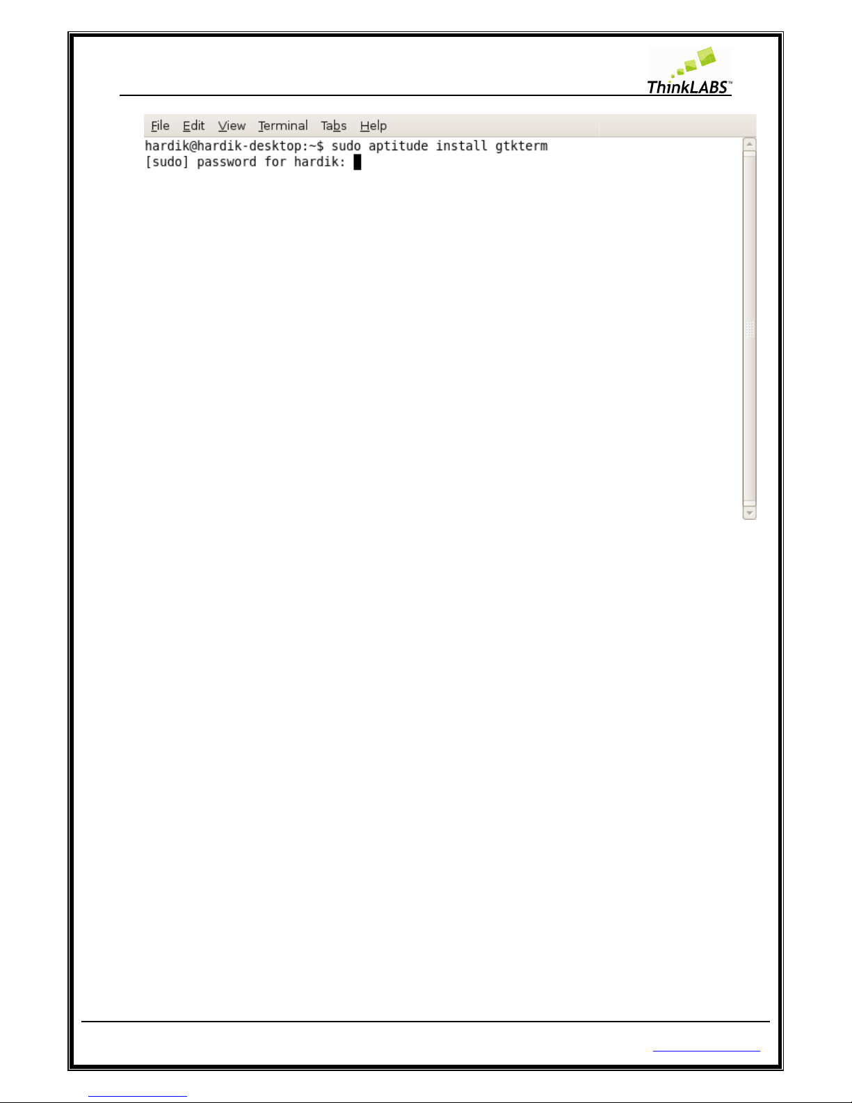
Serial port terminal (
Gtkterm)
The Gtkterm
is analogous to Windows HyperTerminal which is useful for serial commutations between PC
and uNiBoard.
It is a VT102 compatible serial terminal.
STEP 1:
Open terminal and type: “sudo aptitude install gtkterm” and press enter
Page 34 of 129
http://thinklabs.in
Page 35
ThinkLABS
© TRI Technosolutions Pvt Ltd
STEP 2: Enter root password.
STEP 3:
It will show a list of all dependencies installed as shown below
Page 35 of 129
.
http://thinklabs.in
Page 36

ThinkLABS
© TRI Technosolutions Pvt Ltd
STEP 4: Press ALT + F2 an
d type gtkterm and press enter to open the Gtkterm application
Page 36 of 129
http://thinklabs.in
Page 37

ThinkLABS
© TRI Technosolutions Pvt Ltd
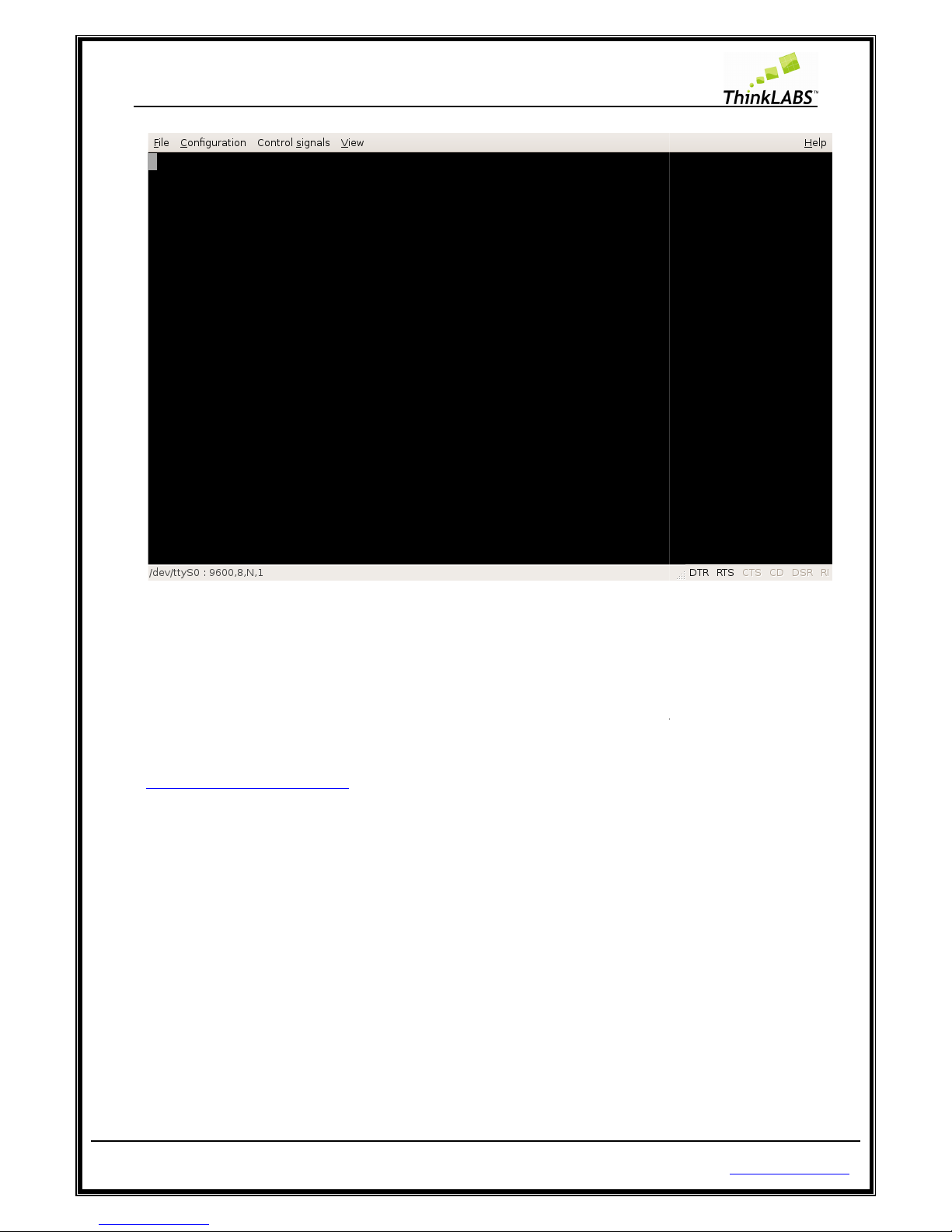
Gtkterm Configurations for setting the
STEP 1:
Press ALT + F2 and type gtkterm and press enter to open the Gtkterm application
STEP 2: Go to
Configuration Menu and choose Port
Page 37 of 129
Baud rate, Parity,
Stop bits
http://thinklabs.in
and click on Run
Page 38

ThinkLABS
© TRI Technosolutions Pvt Ltd
STEP 3:
Select the Port: /dev/ttyS0 if you have connected to the serial
Port.
STEP 4: Select the Speed to the
Baud rate
STEP 5:
Select the Parity as per in your code, you have configured
STEP 6: Select the Stop bits
as per in your code, you have configured
STEP 7:
Select the Bits as per in your code, you have configured for the UART.
STEP 8: Select the
Flow control to none.
STEP 9: Click on OK
Page 38 of 129
communication
as per in your code, you have configured
for the UART.
for
the UART.
http://thinklabs.in
port, if not change the
for the UART.
Page 39
ThinkLABS
© TRI Technosolutions Pvt Ltd
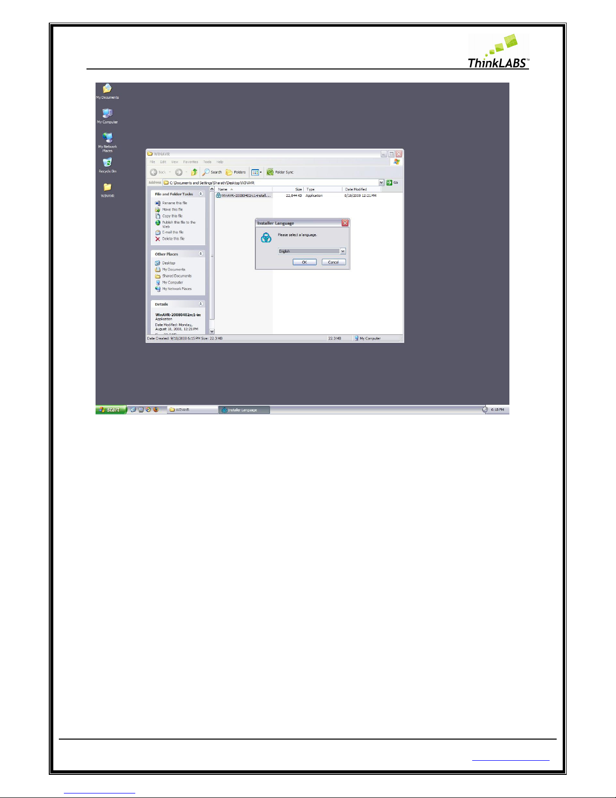
S
oftware Installations for Windows OS
WinAVR (Includes avr-
gcc,
Copy the software packages from the uNiBoard contents
website given below:
http://winavr.sourceforge.net/
After you have this package follow the steps given below:
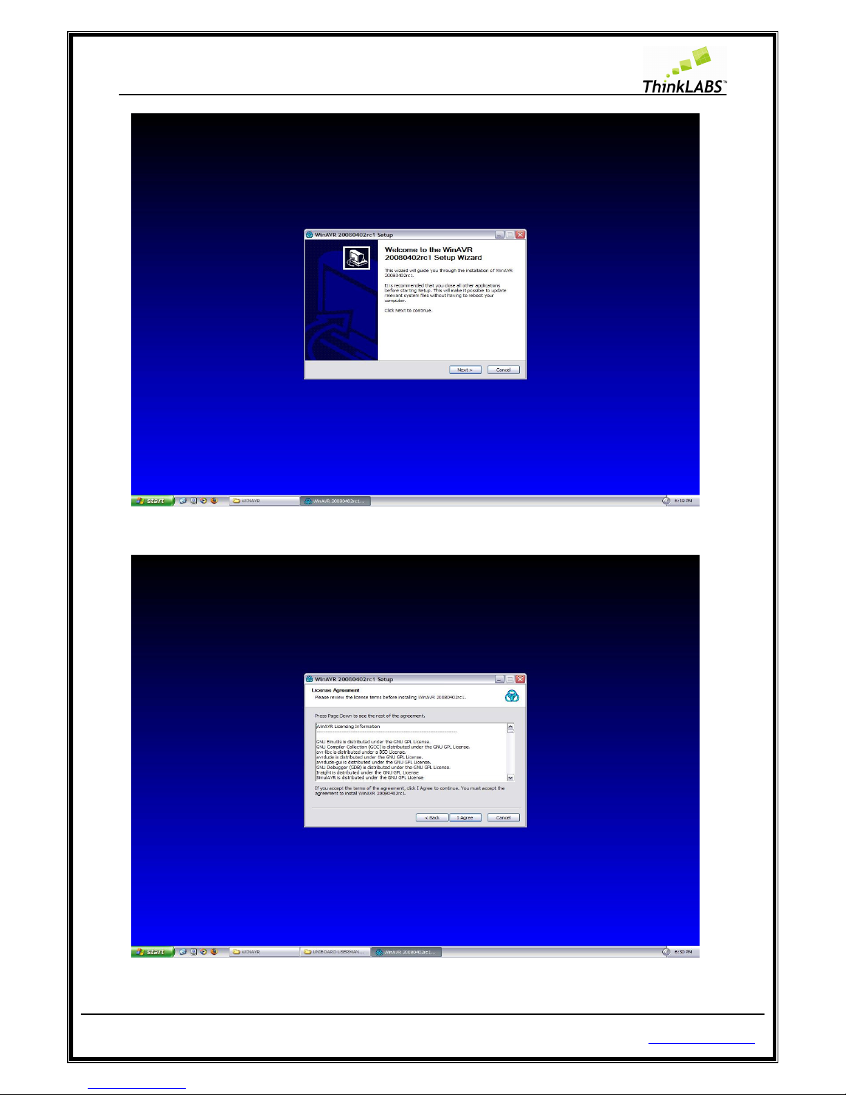
Step 1: R
un the file to install the package.
Page 39 of 129
avr-binutils, avrdude)
on CD
or download latest version of WinAVR from
http://thinklabs.in
Page 40
ThinkLABS
© TRI Technosolutions Pvt Ltd Page 40 of 129 http://thinklabs.in
Step 2: Select the language and press OK.
Page 41
ThinkLABS
© TRI Technosolutions Pvt Ltd Page 41 of 129 http://thinklabs.in
Step 3: click on Next
Step 4: Click on I Agree
Page 42

ThinkLABS
© TRI Technosolutions Pvt Ltd Page 42 of 129 http://thinklabs.in
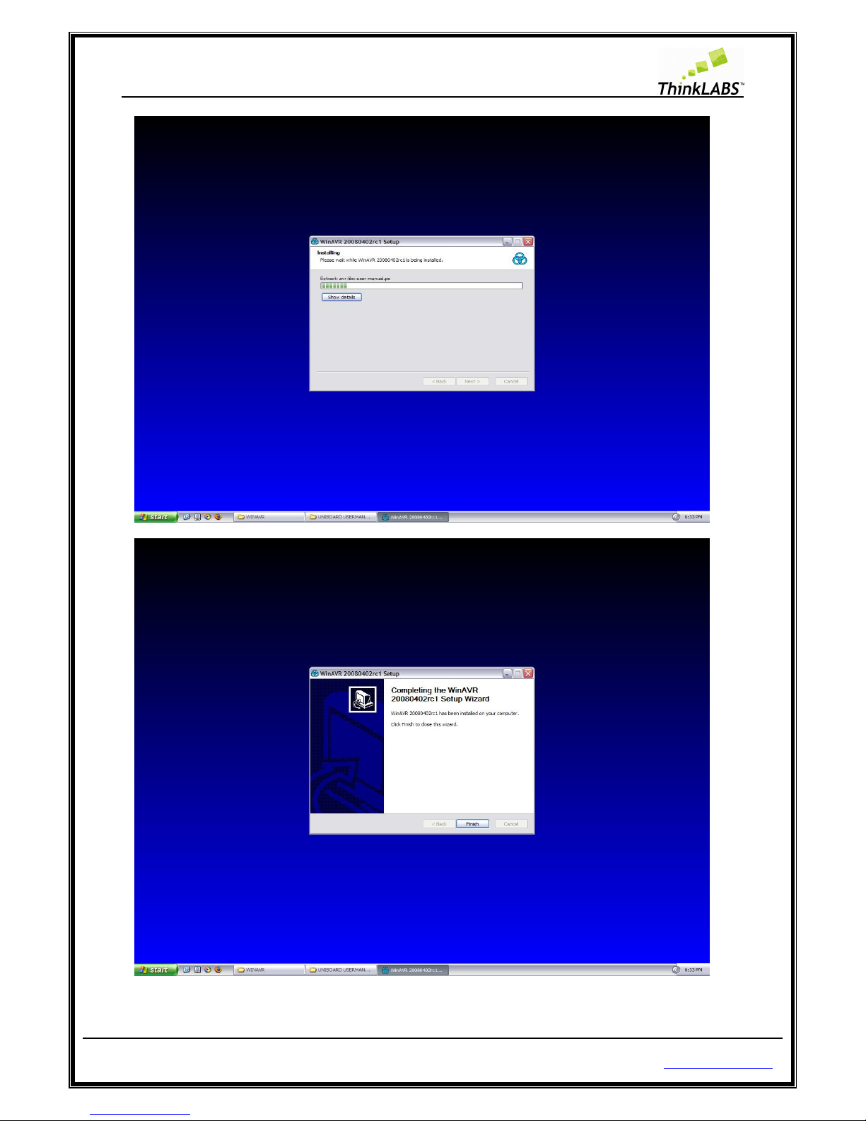
Step 5: Type the destination Folder where you want to install WinAVR and click on Next.
Step 6: Check on all i.e. Install files, Add Directories to path, and Programmer’s Notepad and click on Install.
Step 7: It will display as shown below and then click on finish
Page 43
ThinkLABS
© TRI Technosolutions Pvt Ltd Page 43 of 129 http://thinklabs.in
Page 44

ThinkLABS
© TRI Technosolutions Pvt Ltd Page 44 of 129 http://thinklabs.in
Installing USB drivers for uNiBoard
STEP 1: Insert the uNiBoard USB cable to PC.
STEP 2: If the drivers are not installed then it will display the installation wizard as shown below.
STEP 3: Select the options as install from a list or specific location (Advanced) and click on next. It will display
options as shown below
Page 45

ThinkLABS
© TRI Technosolutions Pvt Ltd Page 45 of 129 http://thinklabs.in
STEP 4: Click on Browse and select the drivers from the CD UNIBOARD CONTENTS directory path as
\UNIBOARD CONTENTS\UNIBOARD_DRIVERS\WINDOWS\usbasp and click on OK
STEP 5: Click on Next.
Page 46

ThinkLABS
© TRI Technosolutions Pvt Ltd Page 46 of 129 http://thinklabs.in
STEP 6: Give the same path of drivers and click on OK
Page 47

ThinkLABS
© TRI Technosolutions Pvt Ltd Page 47 of 129 http://thinklabs.in
STEP 7: Click on Finish.
After the drivers are installed you are ready to program the Board.
Page 48
ThinkLABS
© TRI Technosolutions Pvt Ltd
Programming the Board
NOTE: Refer to the above
section
Getting Started on
Linux
For programming the Board you must first have the hex file to be loaded into the flash section of the
microcontroller. For generating the h
compiler will generate hex file
. Then
the Atmega128 microcontroller.
The following section will guide you
1.
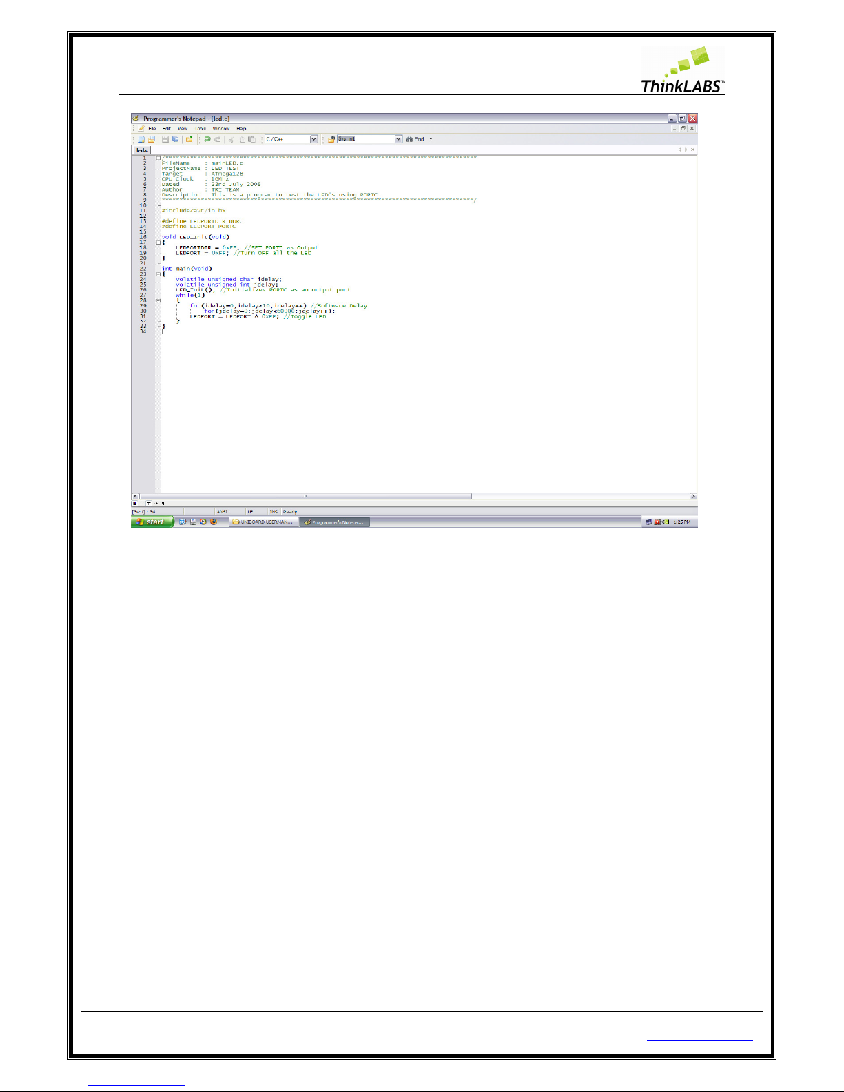
We will write a first program to test LEDs.
As you know LEDs
can be connected
5), we will use the General purpose
LED PORT.
STEP 1:
Open Gedit (refer to chapter 3)
STEP 2:
Create a Project directory
Page 48 of 129
s
to check that you are having all the required
ex file you have to
write an error free code,
using USBasp firmware on Atmega8 microcontroller
on how to program using uNiBoard.
various test PORTs on
UNiBoard using
PORTC as output and connect the FRC
cable between
http://thinklabs.in
software tools.
compile your code and
you can program
FRC cable (refer to chapter
PORTC and the
Page 49

ThinkLABS
© TRI Technosolutions Pvt Ltd
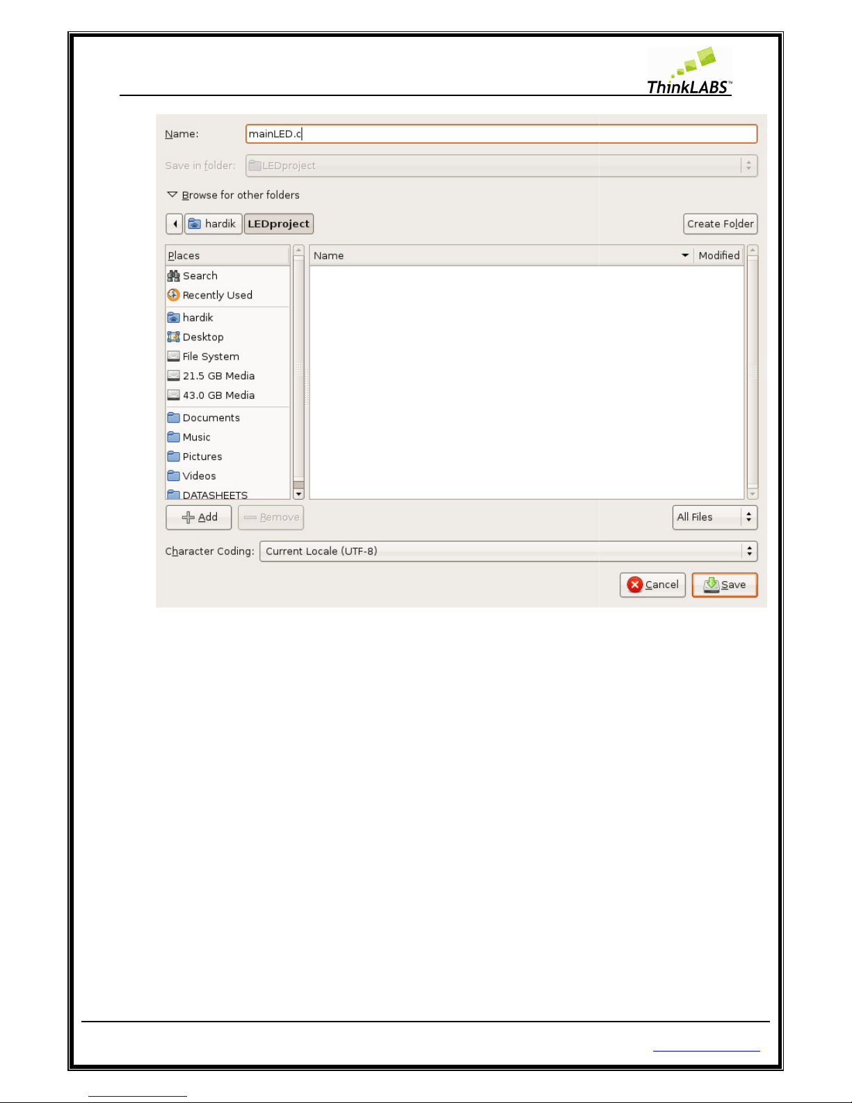
STEP 3:
Save the File as Xfilename.c
Page 49 of 129
http://thinklabs.in
Page 50
ThinkLABS
© TRI Technosolutions Pvt Ltd
STEP 4: Copy the Makefile
(NOTE:
are in script file called as Makefile) in your working
Page 50 of 129
Make is the Utility which calls all the c
ompiler related options which
project directory
http://thinklabs.in
Page 51

ThinkLABS
© TRI Technosolutions Pvt Ltd
STEP 5: Write your code.
Page 51 of 129
http://thinklabs.in
Page 52

ThinkLABS
© TRI Technosolutions Pvt Ltd Page 52 of 129 http://thinklabs.in
STEP 6: Save the file
STEP 7: Edit the Makefile in this file change TARGET = Xfilename (with no extensions and no quotes (“)).
If you put any extensions it won’t work.
NOTE: Xfilename indicates any filename that a user will use.
Page 53

ThinkLABS
© TRI Technosolutions Pvt Ltd
STEP 8: Save the Makefile.
STEP 9:
On Linux based systems, you can use one of the makefiles of the sample codes marked as
Makefile_LINUX
by renaming it to Makefile, failing which you will get an error saying “No rule to make
target. Stop.”
STEP 10: On the Embedded
terminal goto t
the previously compiled files in the project dir
Page 53 of 129
terminal goto t
he Project directory and type:
make clean
ectory).
http://thinklabs.in
(this will remove all
Page 54

ThinkLABS
© TRI Technosolutions Pvt Ltd
STEP 10: Type: make all
(this will compile the sourc
code).
Page 54 of 129
e file and generate hex file if
http://thinklabs.in
there are no errors in
Page 55

ThinkLABS
© TRI Technosolutions Pvt Ltd
STEP 11: type:
make program
Page 55 of 129
(this will burn the hex into the microcontroller)
http://thinklabs.in
Page 56

ThinkLABS
© TRI Technosolutions Pvt Ltd
1.1.
Changing the Fuse settings
NOTE:
The fuse setting must be changed only if
The ATmega128 has three fuse bytes
Byte.
Refer the ATmega128 datasheet for information on what the fuse bits are. To cut things short,
Fuse bits
configure various options like EEPROM SAVE, Programming Enable,
startup time, clock source etc.
The following Table represents
Extended Fuse Byte
BIT No.
-
-
-
-
Page 56 of 129
required.
referred as High Fuse Byte, Low Fuse Byte and Extended Fuse
Extended Fuse Byte:
Description
7 -
6 -
5 -
4 -
http://thinklabs.in
Clock Speed, Oscillator
Default Value
1
1
1
1
Page 57

ThinkLABS
© TRI Technosolutions Pvt Ltd Page 57 of 129 http://thinklabs.in
- 3 - 1
- 2 - 1
M103C
1
Atmega103 compatibility mode
0
(programmed)
WDTON
0
Watchdog timer is always ON
1
(unprogrammed)
The following Table represents High Fuse Byte:
High Fuse Byte
BIT No.
Description
Default Value
OCDEN
7
Enable OCD
1 (unprogrammed,
OCD disabled)
JTAGEN
6
Enable JTAG
0 (programmed,
JTAG enabled)
SPIEN
5
Enable serial programming and
data downloading
0 (programmed SPI
prog. enabled)
CKOPT
4
Oscillator options
1 (unprogrammed)
EESAVE
3
EEPROM memory is preserved
through chip erase
1 (unprogrammed,
EEPROM not
preserved)
BOOTSZ1
2
Select Boot Size
0 (programmed)
BOOTSZ0
1
Select Boot Size
0 (programmed)
BOOTRST
0
Select Reset Vector
1 (unprogrammed)
The following Table represents Low Fuse Byte:
Low Fuse Byte
BIT No.
Description
Default Value
BODLEVEL
7
Brown out detector trigger level
1 (programmed)
BODEN
6
Brown out detector enable
1 (programmed,
BOD disabled)
SUT1
5
Select start
-
up time
1 (unprogrammed)
SUT0
4
Select start
-
up time
0 (programmed)
CKSEL3
3
Select Clock source
0 (programmed)
CKSEL2
2
Select Clock source
0 (programmed)
Page 58
ThinkLABS
© TRI Technosolutions Pvt Ltd
CKSEL1
CKSEL0
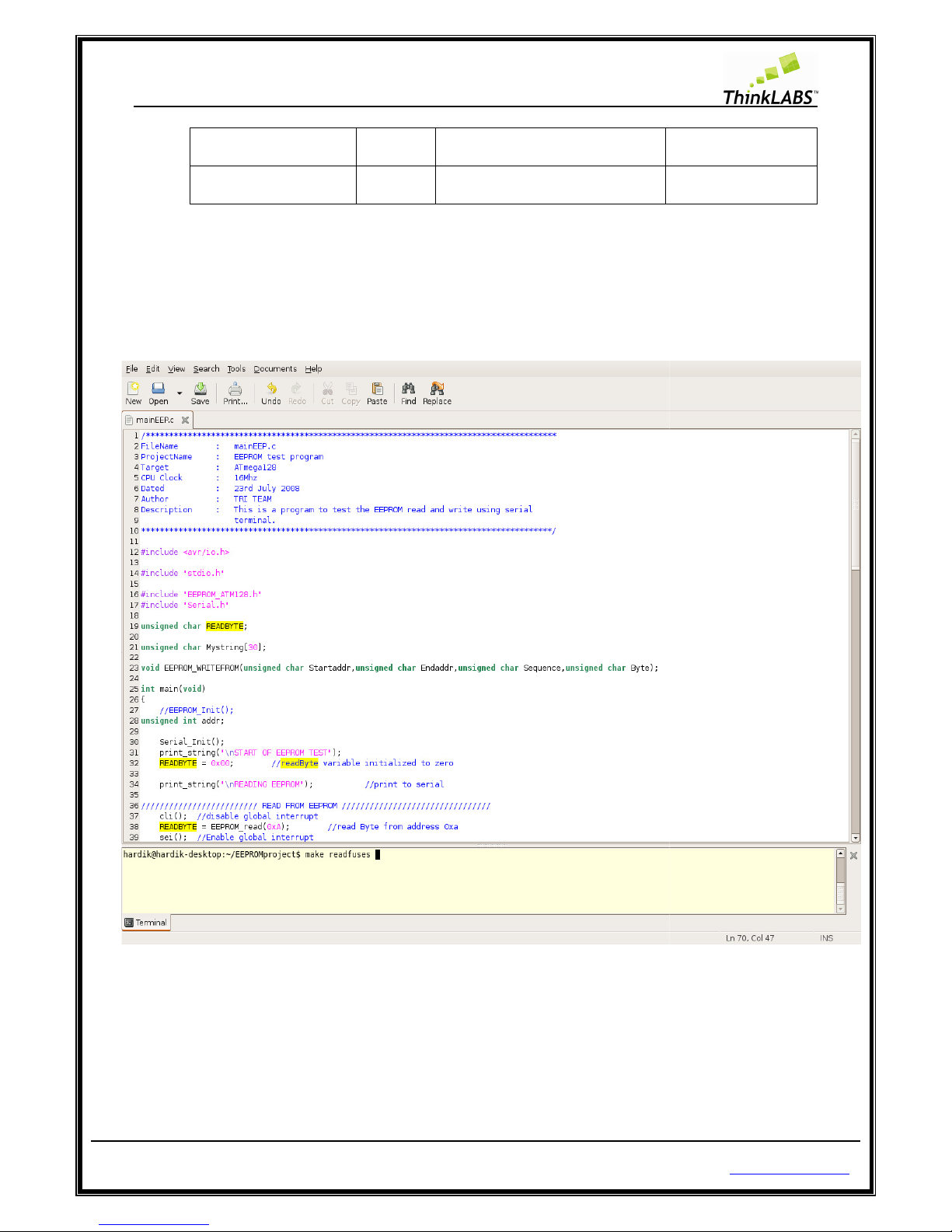
The Make utility allows programming the fuse bits. The following
the fuse bits.
STEP 1: On Embedded
terminal type make readfuses (This will read the fuse setting currently present on the
board) as shown below.
The output will be displayed as shown below:
Page 58 of 129
1 Select Clock source
0 Select Clock source
procedure will
http://thinklabs.in
0 (programmed)
1 (unprogrammed)
help you configuring
Page 59
ThinkLABS
© TRI Technosolutions Pvt Ltd
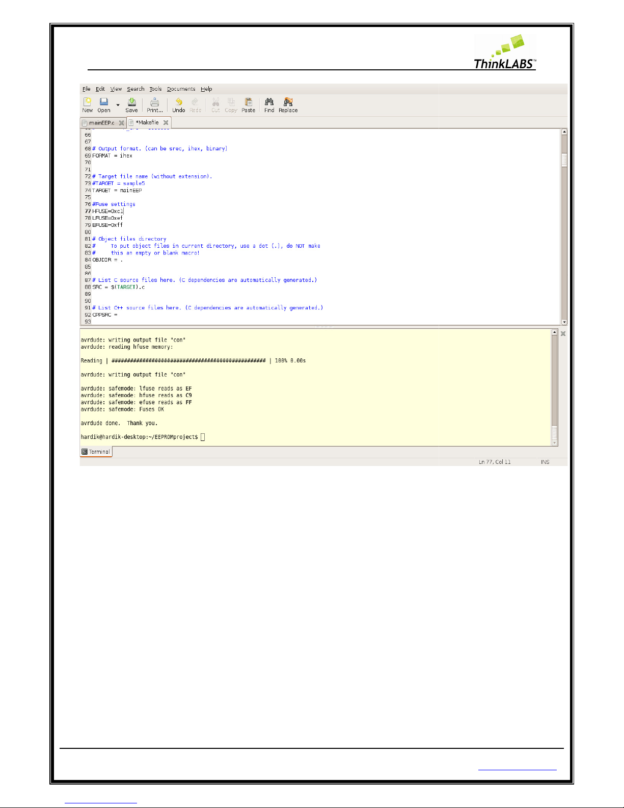
STEP 2: Edit the Makefile as shown
in the
labels to be edited) that is required.
STEP 3: On Embedded
terminal type make fuses (This will read the fuse setting currently present on the board)
as shown below.
NOTE: DO NOT MESS WI
TH THE FUSE BITS UNLESS YOU ARE VERY SURE OF WHAT EFFECT IT WOULD HAVE,
FAILING WHICH THE PROGRAM MEMORY MIGHT BE LOCKED FOR WRITING.
Page 59 of 129
above picture as per the fuse setting
(HFUSE, LFUSE and EFUSE are the
http://thinklabs.in
Page 60

ThinkLABS
© TRI Technosolutions Pvt Ltd
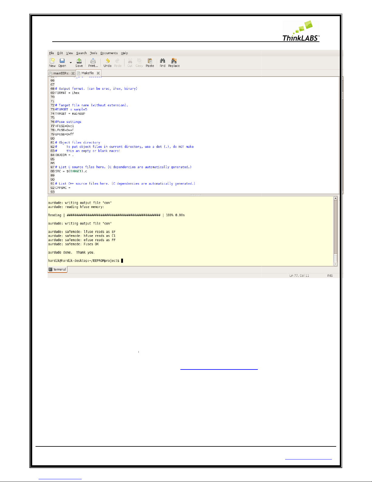
STEP 4: Again on the embedded
terminal type make readfuses to verify that fuse bit have been saved.
Page 60 of 129
http://thinklabs.in
Page 61

ThinkLABS
© TRI Technosolutions Pvt Ltd
As shown below the
fuse setting have been modified successfully.
Page 61 of 129
http://thinklabs.in
Page 62
ThinkLABS
© TRI Technosolutions Pvt Ltd
Getting Started on Windows
The sample programs have
been given
“\UNIBOARD CONTENTS\
UNIBOARD_SAMPLE_CODES
“\UNIBOARD CONTENTS\
UNIBOARD_SAMPLE_CODES
Or you can downl
oad it from our website at link
Page 62 of 129
in the CD folder named
\NON_RTOS\” and
\ RTOS”
http://thinklabs.in/download/
http://thinklabs.in
Page 63

ThinkLABS
© TRI Technosolutions Pvt Ltd Page 63 of 129 http://thinklabs.in
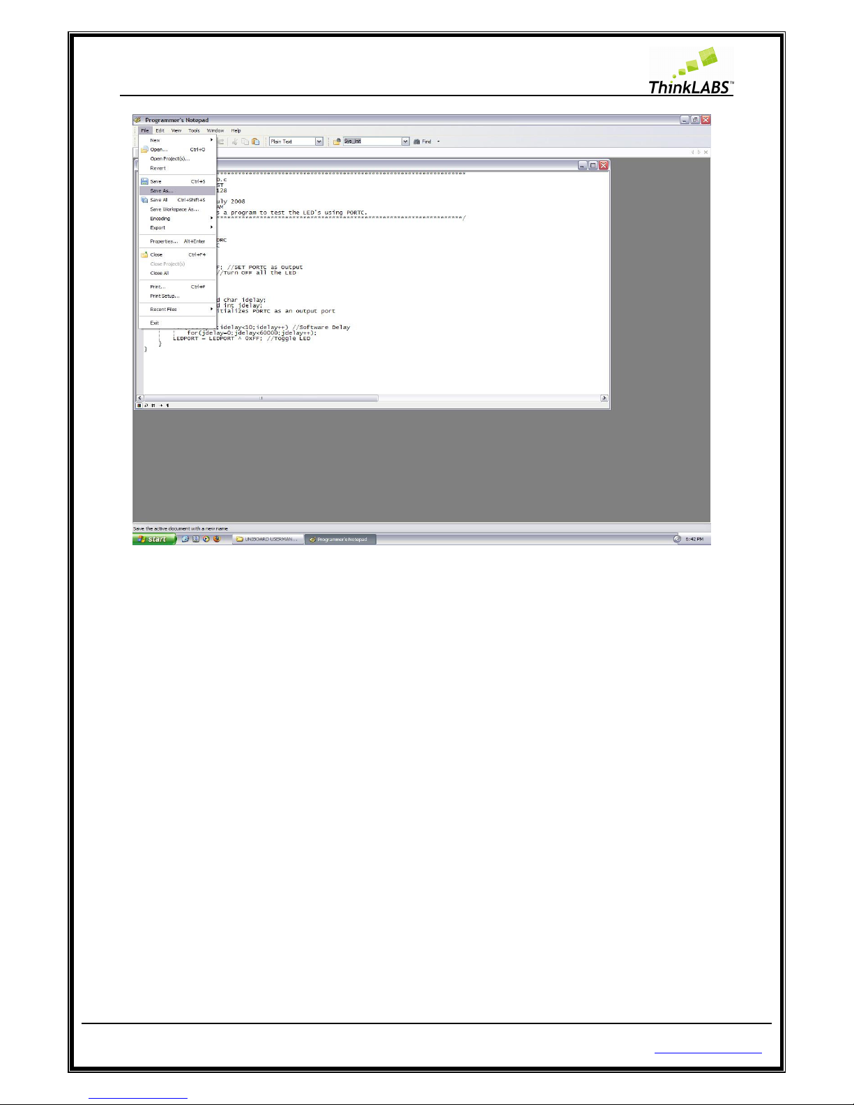
Text Editor (programmer’s Notepad)
Step 1: Select Programmer’s Notepad from Start menu->Programs->Win-avr->Programmers Notepad.
Step 2: Type your code here and save the file as shown below:
Page 64
ThinkLABS
© TRI Technosolutions Pvt Ltd Page 64 of 129 http://thinklabs.in
STEP 3: Save the file as anyfilename.c
Page 65

ThinkLABS
© TRI Technosolutions Pvt Ltd Page 65 of 129 http://thinklabs.in
STEP 4: You can view the line numbers by selecting view menu ->Line Numbers.
Page 66
ThinkLABS
© TRI Technosolutions Pvt Ltd Page 66 of 129 http://thinklabs.in
Page 67

ThinkLABS
© TRI Technosolutions Pvt Ltd Page 67 of 129 http://thinklabs.in
Compile the code and program the board on Windows (Command Prompt)
STEP 1: Open the command prompt by selecting Start->Run and type cmd
STEP 2: It will display the Command prompt and goto your project directory.
Page 68

ThinkLABS
© TRI Technosolutions Pvt Ltd Page 68 of 129 http://thinklabs.in
STEP 3: You must have the Makefile in your project directory. In case of windows you would find a file
named Makefile_WINDOWS, which you can rename as Makefile. Make sure that you have only a
single Makefile in your working directory.
STEP 4: Edit the Makefile and set Target = filename of your C file and save the file.
Page 69

ThinkLABS
© TRI Technosolutions Pvt Ltd Page 69 of 129 http://thinklabs.in
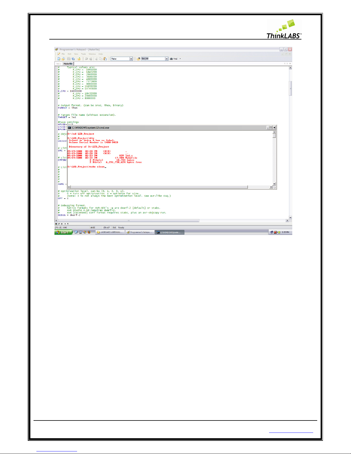
STEP 5: In command prompt window, type command as make clean and press enter
Page 70
ThinkLABS
© TRI Technosolutions Pvt Ltd Page 70 of 129 http://thinklabs.in
STEP 6: This will remove all previously files created due to compilation as shown below:
Page 71

ThinkLABS
© TRI Technosolutions Pvt Ltd Page 71 of 129 http://thinklabs.in
STEP 7: type make all and press enter
Page 72

ThinkLABS
© TRI Technosolutions Pvt Ltd Page 72 of 129 http://thinklabs.in
STEP 8: This command will compile the file and generate a Hex file. Type dir and press enter and check if
there hex file generated as shown below.
Page 73

ThinkLABS
© TRI Technosolutions Pvt Ltd Page 73 of 129 http://thinklabs.in
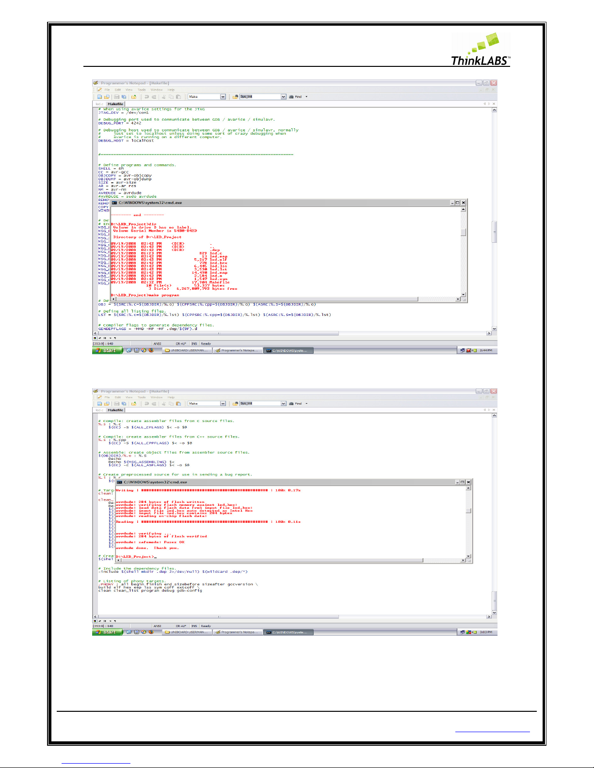
STEP 9: For loading the compiled output to the board the board i.e. burning the hex file into the Atmega128
type command as make program.
Page 74
ThinkLABS
© TRI Technosolutions Pvt Ltd Page 74 of 129 http://thinklabs.in
STEP 10: press enter
Page 75
ThinkLABS
© TRI Technosolutions Pvt Ltd Page 75 of 129 http://thinklabs.in
Using hyper terminal of windows
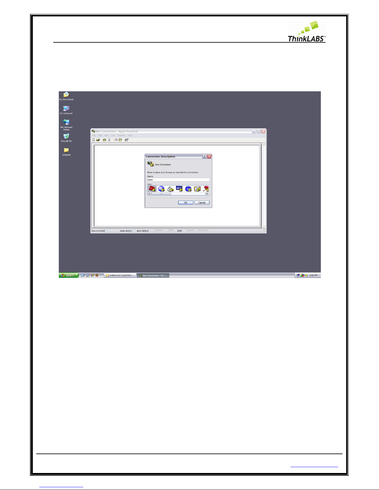
STEP 1: Run Hyper Terminal start menu->all programs->accessories->Communications->HyperTerminal.
STEP 2: Type name for make new connection
STEP 3: Select the serial port (usually it is COM1)
Page 76
ThinkLABS
© TRI Technosolutions Pvt Ltd Page 76 of 129 http://thinklabs.in
Page 77

ThinkLABS
© TRI Technosolutions Pvt Ltd Page 77 of 129 http://thinklabs.in
STEP 4: Select the Baud rate (9600), Data bits (8 bits), parity (none), stop bits (1), and flow control (none) as
shown below.
Page 78

ThinkLABS
© TRI Technosolutions Pvt Ltd Page 78 of 129 http://thinklabs.in
STEP 5: You can even save this connection from File->save so that you need not set all the settings again.
Page 79

ThinkLABS
© TRI Technosolutions Pvt Ltd Page 79 of 129 http://thinklabs.in
Getting Started with RTOS (uC/OS-II) on Windows OS
uC/OS-II Hardware and Software Architecture
Before starting of with the uC/OS-II programming you need to know its file structure i.e. how the uC/OS-II
source code and its ports are structured. The diagram below gives an idea of the way in which these files
have been maintained. For further information on this, refer to MicroC/OS-II, The Real Time Kernel by Jean
Labrosse.
Page 80

ThinkLABS
© TRI Technosolutions Pvt Ltd Page 80 of 129 http://thinklabs.in
Every RTOS project/source code consists of (as shown in the above figure):
• Portable kernel code: This is generally a code written in ANSI C which can be ported to any platform
fulfilling certain requirements like memory footprint, computational power, number of registers etc.
• BSP or port files: These are specific to an architecture, so for every architecture / board there is a
unique BSP / port files.
• Configuration files: These are files which can be used to optimize the kernel and reduce the memory
footprint of the kernel image based on what features of the kernel would be used by any application
program.
• Application program: This is generally written on top of the kernel code and utilizes kernel API’s and
functions exported by the OS for the users of the RTOS.
Code, Compile and program the RTOS (uC/OS-II) programs on Linux OS
NOTE : You Should have the required software tools i.e. text editor, compiler, programmer and serial
terminal as shown in the section sub-section Software Installations for Linux OS. Also refer to the sub-
section Getting started on Linux.
STEP 1: Copy the “Micrium” directory from the UNIBOARD CONTENTS from the path " \UNIBOARD
CONTENTS\UNIBOARD_UCOS_DOCS" to the user's home directory.
NOTE: You can go to the user’s home directory from menu Places >> Home Folder.
STEP 2: Copy the sample codes given in the UNIBOARD CONTENTS from the path “\UNIBOARD
CONTENTS\UNIBOARD_SAMPLE_CODES\ RTOS” onto your disk. In the project / sample code that you want
to execute, RENAME Makefile_LINUX to Makefile.
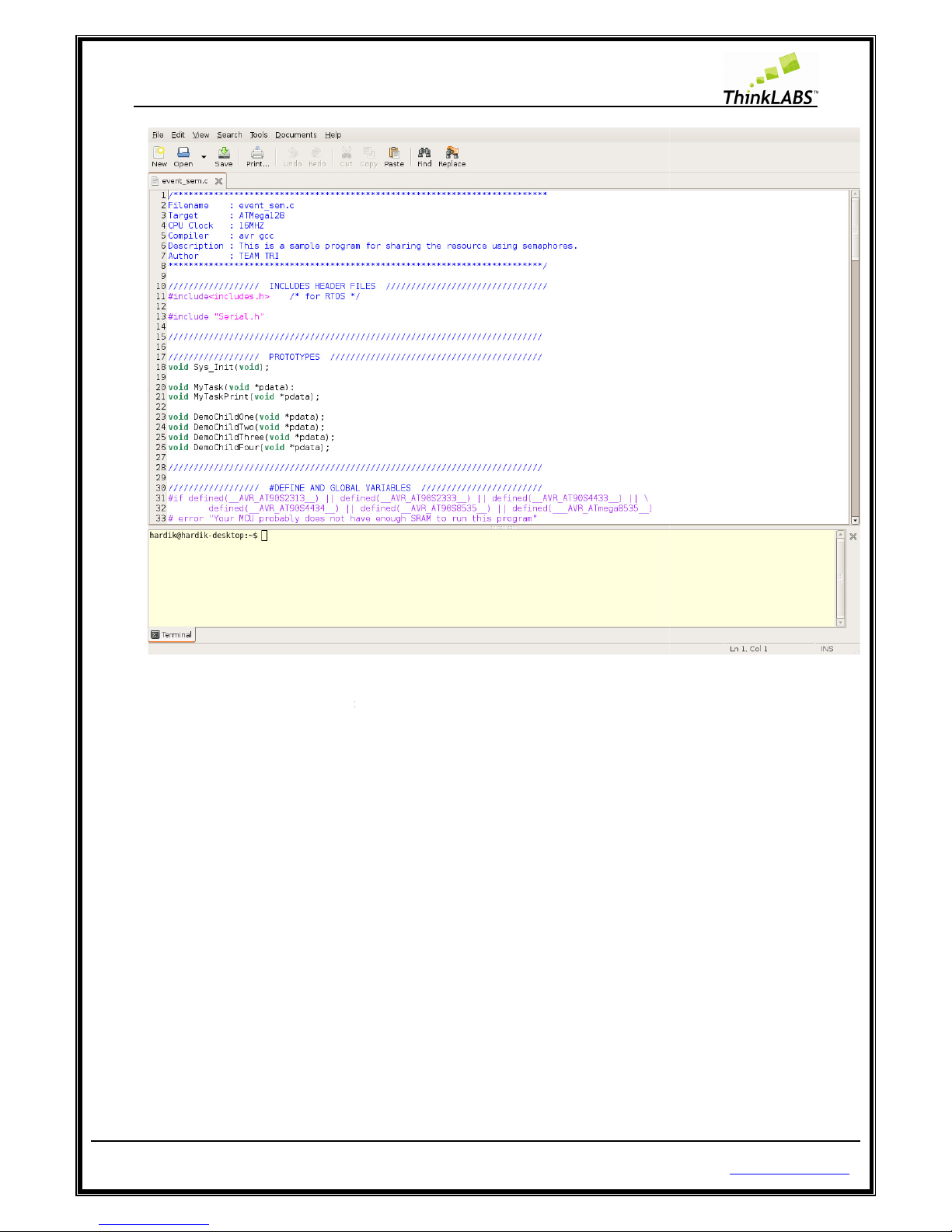
STEP 3: Open the event_sem.c file using Gedit Editor (refer to the sub-section getting started on Linux).
Page 81
ThinkLABS
© TRI Technosolutions Pvt Ltd
STEP 4: Go to the current
program
on Bottom terminal and select change directory
Page 81 of 129
directory from Gedit Embedded terminal
using cd
(refer to the sub-
section getting started on Linux
http://thinklabs.in
command or right click
).
Page 82

ThinkLABS
© TRI Technosolutions Pvt Ltd
STEP 5: Type make clean
on Gedit Embedded terminal.
Page 82 of 129
http://thinklabs.in
Page 83

ThinkLABS
© TRI Technosolutions Pvt Ltd
STEP 6: Type make all
on Gedit Embedded terminal.
Page 83 of 129
http://thinklabs.in
Page 84

ThinkLABS
© TRI Technosolutions Pvt Ltd
STEP 7: Type make program
on Gedit Embedded terminal.
Page 84 of 129
http://thinklabs.in
Page 85

ThinkLABS
© TRI Technosolutions Pvt Ltd
STEP 8:
Enter the root password to program the Board
Page 85 of 129
and press enter (if prompted)
http://thinklabs.in
.
Page 86

ThinkLABS
© TRI Technosolutions Pvt Ltd
STEP 9: Turn OFF the uNiBoard
Page 86 of 129
after the program has been loaded successfully as shown below
http://thinklabs.in
.
Page 87

ThinkLABS
© TRI Technosolutions Pvt Ltd
STEP 10: Open Gtkterm (
refer to the sub
Stop bits).
Page 87 of 129
-
section Gtkterm Configurations for settin
http://thinklabs.in
g the Baud rate, Parity,
Page 88

ThinkLABS
© TRI Technosolutions Pvt Ltd
STEP 11: Turn ON
the uNiBoard and
Page 88 of 129
Output will be displayed as shown below
on Gtkterm
http://thinklabs.in
.
Page 89

ThinkLABS
© TRI Technosolutions Pvt Ltd Page 89 of 129 http://thinklabs.in
Code, Compile and program the RTOS (uC/OS-II) programs on Windows OS
NOTE: You Should have the required software tools i.e. text editor, compiler, programmer, serial terminal
and required drivers for programmer as shown in the sub-section Software Installations for Windows OS.
STEP 1: Copy the Micrium directory from CD Contents directory path as “\UNIBOARD
CONTENTS\UNIBOARD_UCOS_DOCS\” to “C:\”.
STEP 2: Go to the UNIBOARD CONTENT on CD in the directory \UNIBOARD
CONTENTS\UNIBOARD_SAMPLE_CODES\ RTOS \“ and copy it your disk.
STEP 3: Go to the RTOS directory that you have just loaded on your disk. Select one of the sample code e.g:
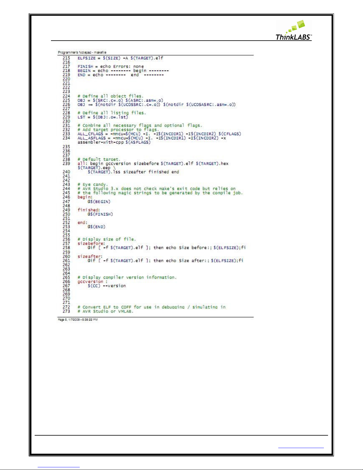
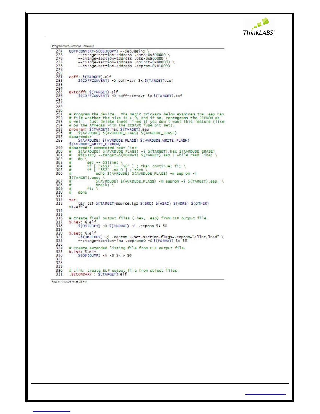
3_SEMAPHORES. Rename the Makefile_WINDOWS to Makefile in the current example directory.
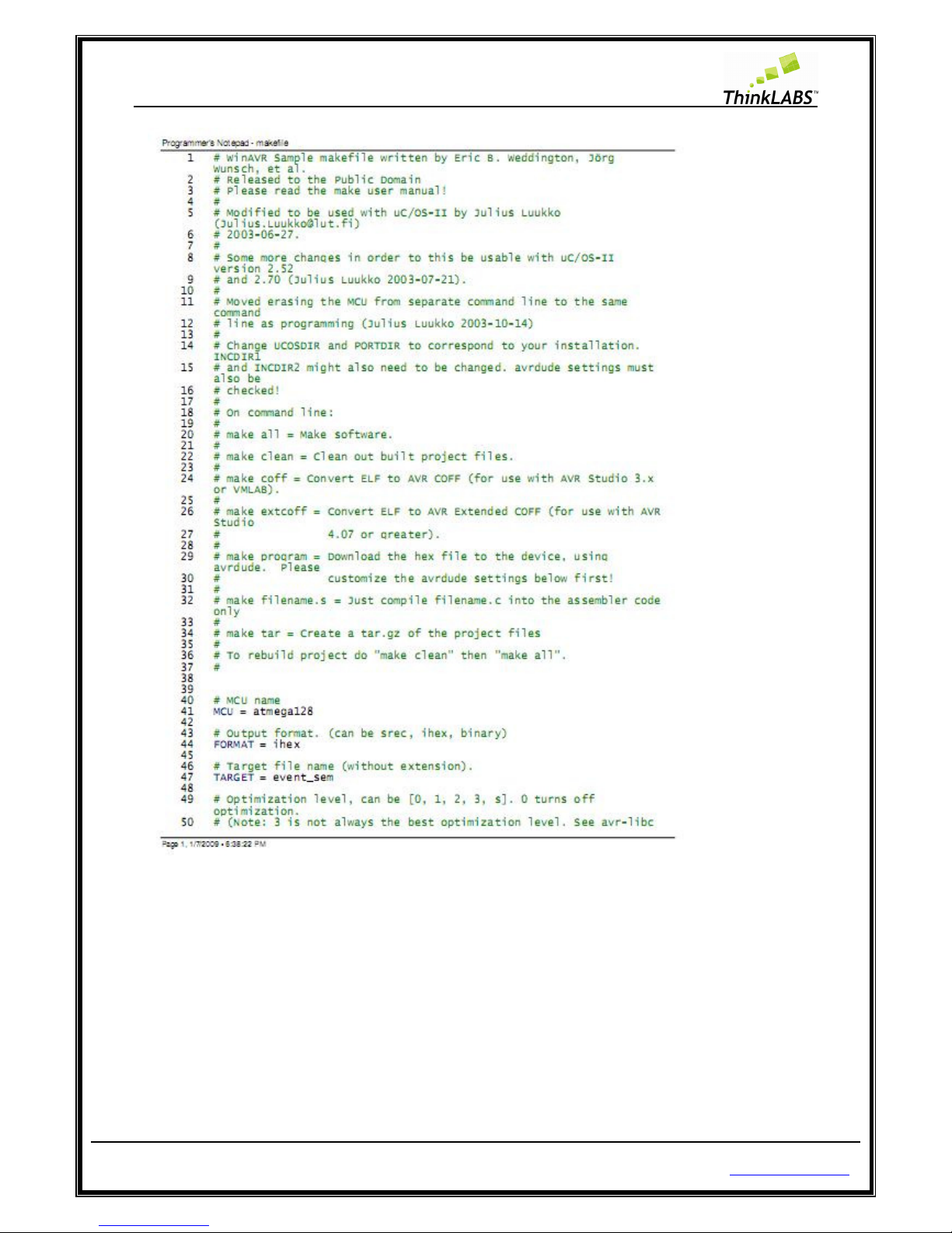
STEP 4: Open the Makefile using Text Editor and search for the TARGET label. In this example it is
event_sem.c so assign TARGET = event_sem as shown below at line 47.
NOTE 1: In Makefile Target = Filename should be without any extensions as shown below at line 47.
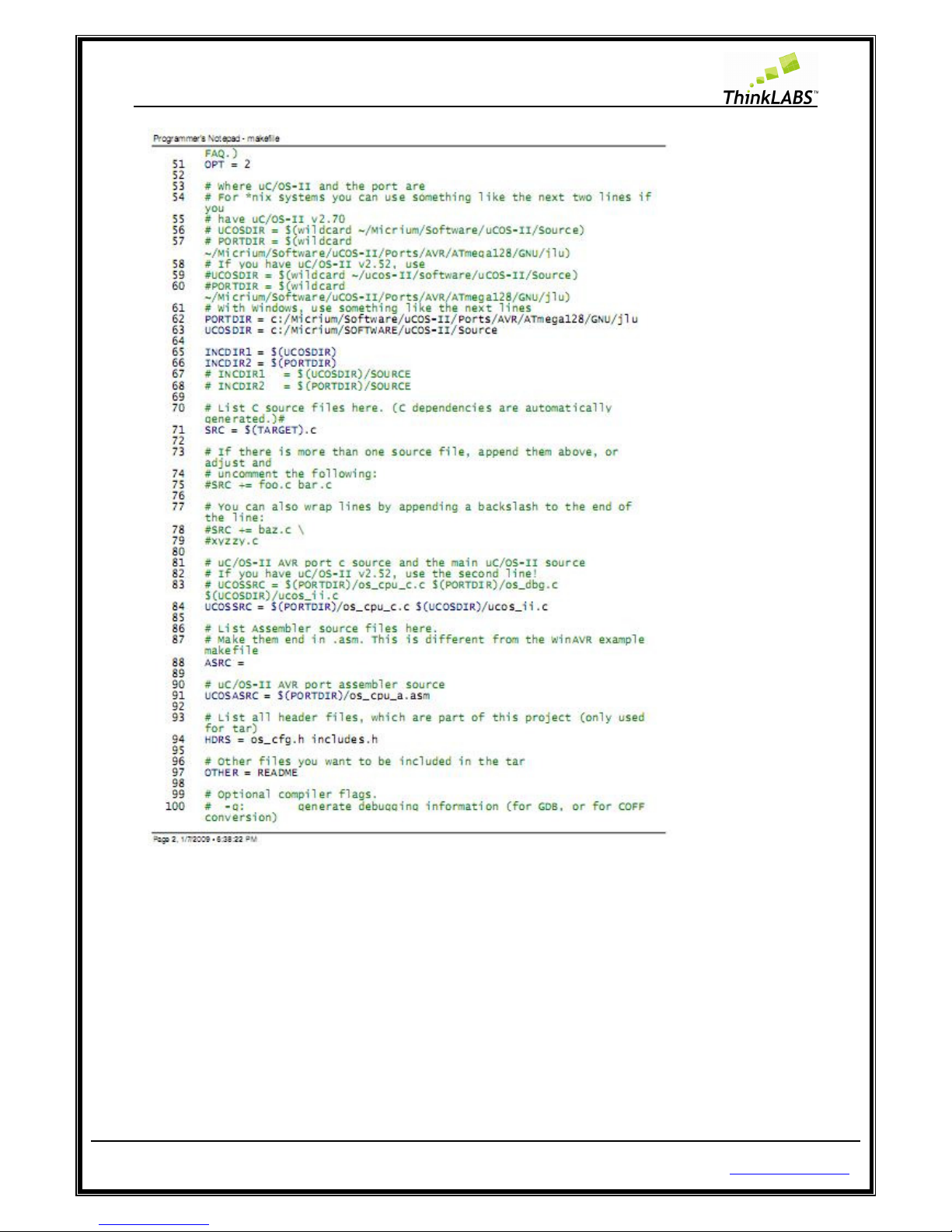
NOTE 2: Check the Path setting for uCOS-II Makefile as shown below (for Windows OS only) at line 62 and
63. See that it is complying with the path shown below in the screenshot.
NOTE 3: Check the programmer’s Avrdude options as shown below (for Windows OS only) at line 208.
Page 90
ThinkLABS
© TRI Technosolutions Pvt Ltd Page 90 of 129 http://thinklabs.in
Page 91
ThinkLABS
© TRI Technosolutions Pvt Ltd Page 91 of 129 http://thinklabs.in
Page 92

ThinkLABS
© TRI Technosolutions Pvt Ltd Page 92 of 129 http://thinklabs.in
Page 93

ThinkLABS
© TRI Technosolutions Pvt Ltd Page 93 of 129 http://thinklabs.in
Page 94
ThinkLABS
© TRI Technosolutions Pvt Ltd Page 94 of 129 http://thinklabs.in
Page 95
ThinkLABS
© TRI Technosolutions Pvt Ltd Page 95 of 129 http://thinklabs.in
Page 96

ThinkLABS
© TRI Technosolutions Pvt Ltd Page 96 of 129 http://thinklabs.in
Page 97

ThinkLABS
© TRI Technosolutions Pvt Ltd Page 97 of 129 http://thinklabs.in
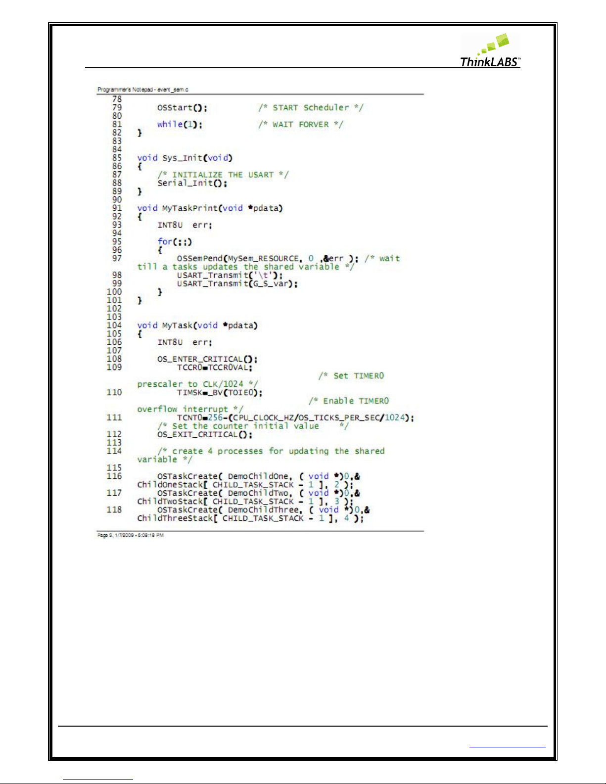
STEP 5: Open event_sem.c from the current directory and the code will be displayed as shown below.
Page 98

ThinkLABS
© TRI Technosolutions Pvt Ltd Page 98 of 129 http://thinklabs.in
Page 99

ThinkLABS
© TRI Technosolutions Pvt Ltd Page 99 of 129 http://thinklabs.in
Page 100
ThinkLABS
© TRI Technosolutions Pvt Ltd Page 100 of 129 http://thinklabs.in
 Loading...