

Page 1
Thinkify, LLC
TR-65 RFID Reader
User Guide and Protocol Reference
Version A
October 2014
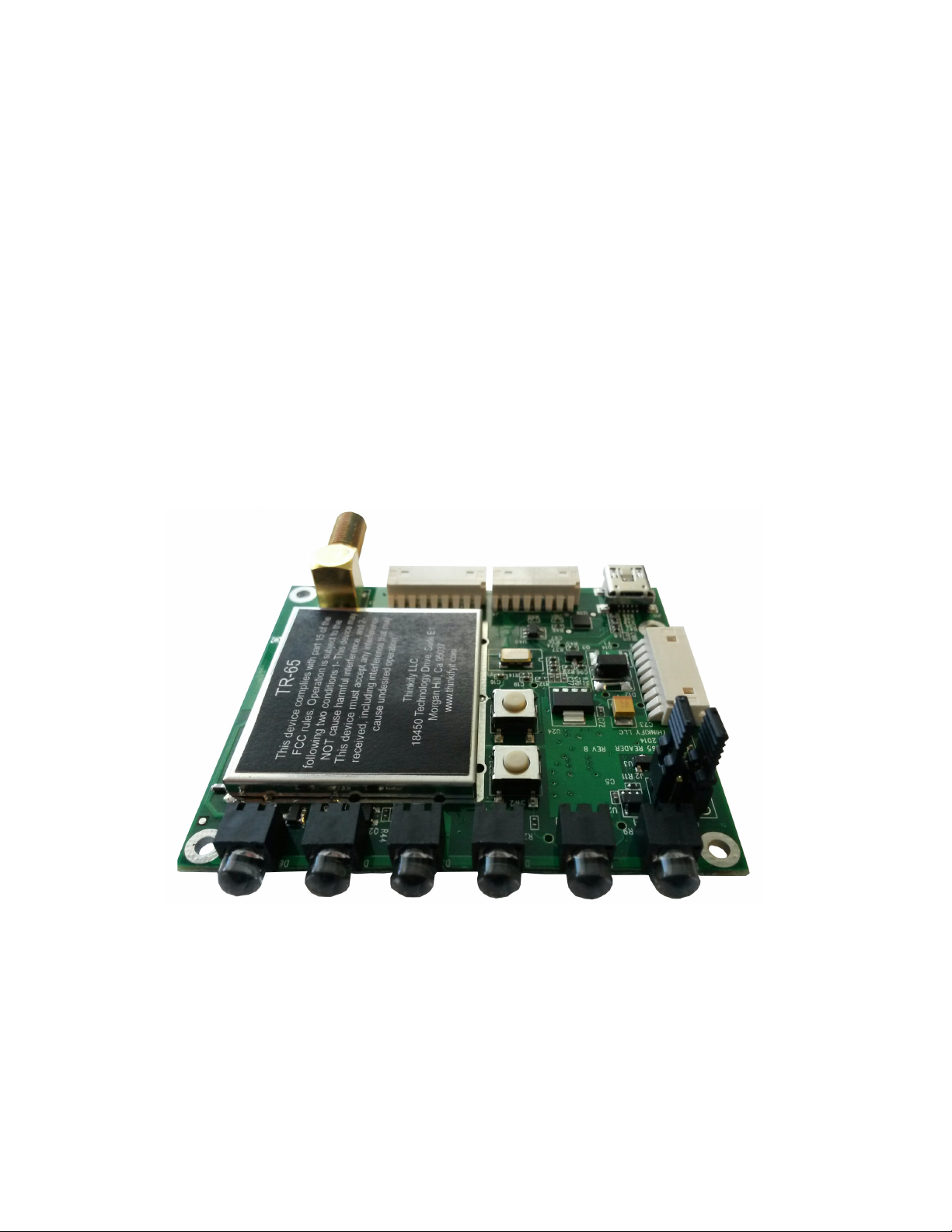
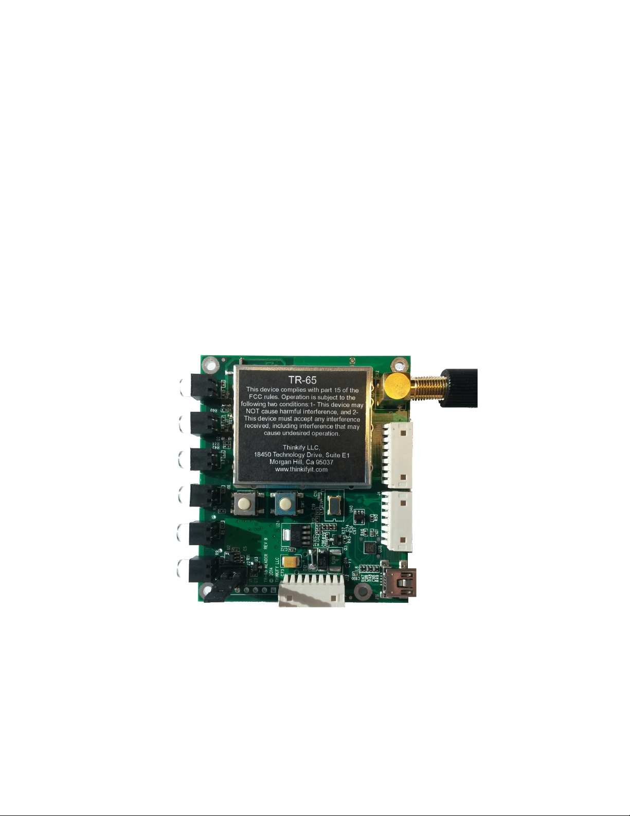
The TR-65 RFID READER
DCN-TF-010045-A
1
Page 2
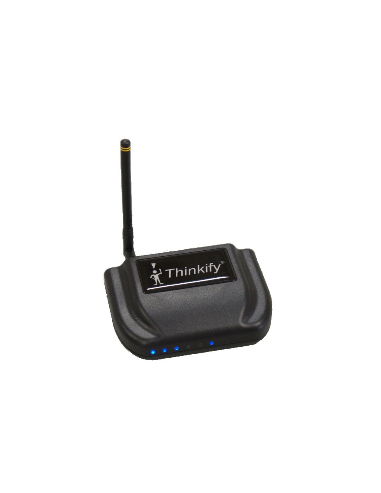
TR-65 inside of a TR-200 Enclosure
The TR-65 RFID READER
DCN-TF-010045-A
2
Page 3

Notices
Copyright ©2010 Thinkify, LLC. All rights reserved.
Thinkify, LLC has intellectual property rights relating to technology embodied in the products
described in this document, including without limitation certain patents or patent pending
applications in the U.S. or other countries.
This document and the products to which it pertains are distributed under licenses restricting
their use, copying, distribution and decompilation. No part of this product documentation may
be reproduced in any form or by any means without the prior written consent of Thinkify, LLC
and its licensors, if any. Third party software is copyrighted and licensed from Licensors.
Thinkify, the Thinkify logo, TR-65 and other graphics, logos, and service names used in this
document are trademarks of Thinkify, LLC in the U.S. and other countries. All other trademarks
are the property of their respective owners. U.S. Government approval required when
exporting the product described in this documentation.
Federal Acquisitions: Commercial Software -- Government Users Subject to Standard License
Terms and Conditions. U.S. Government: If this Software is being acquired by or on behalf of
the U.S. Government or by a U.S. Government prime contractor or subcontractor (at any tier),
then the Government's rights in the Software and accompanying documentation shall be only
as set forth in this license; this is in accordance with 48 C.F.R. 227.7201 through 227.7202-4 (for
Department of Defense (DoD) acquisitions) and with 48 C.F.R. 2.101 and 12.212 (for non-DoD
acquisitions).
Notices
DOCUMENTATION IS PROVIDED “AS IS” AND ALL EXPRESS OR IMPLIED CONDITIONS,
REPRESENTATIONS AND WARANTEES, INCLUDING ANY IMPLIED WARRANTY OF
MERCHANTABILITY, FITNESS FOR APARTICULAR PURPOSE OR NON-INFRINGMENT ARE
HEREBY DISCLAIMED, EXCEPT TO THE EXTENT THATSUCH DISCLAIMERS ARE HELD TO BE
LEGALLY INVALID.
Note Regarding RF Exposure
This equipment complies with FCC radiation exposure limits set forth for an uncontrolled
environment. This equipment should be installed and operated with minimum distance of
20cm between the radiator (antenna) and your body. This transmitter must not be co-located
or operating in conjunction with any other antenna or transmitter.
FCC Notice and Cautions
Any changes or modifications to this device not expressly approved by Thinkify, LLC could void
the user's authority to operate the equipment.
The TR-65 RFID READER
DCN-TF-010045-A
3
Page 4

FCC Notice and Cautions
This device complies with Part 15 of the FCC Rules. Operation is subject to the following two
conditions: (1) this device may not cause harmful interference, and (2) this device must accept
any interference received, including interference that may cause undesired operation.
This equipment has been tested and found to comply with the limits for a Class B digital
device, pursuant to Part 15 of the FCC Rules. These limits are designed to provide reasonable
protection against harmful interference in a residential installation. This equipment generates,
uses and can radiate radio frequency energy and, if not installed and used in accordance with
the instructions, may cause harmful interference to radio communications. However, there is no
guarantee that interference will not occur in a particular installation. If this equipment does
cause harmful interference to radio or television reception, which can be determined by
turning the equipment off and on, the user is encouraged to try to correct the interference by
one or more of the following measures:
• Reorient or relocate the receiving antenna.
• Increase the separation between the equipment and receiver.
• Connect the equipment into an outlet on a circuit different from that to
which the receiver is connected.
• Consult the dealer or an experienced radio/TV technician for help.
Revision History
1 October 2014 – TR-65 User Guide Created
The TR-65 RFID READER
DCN-TF-010045-A
4
Page 5

About Thinkify, LLC
Thinkify, LLC is a wireless technology company specializing in RFID hardware and software
products. With 30 years of combined experience in RFID and over 35 patents in the field, our
founding team is one of the technically strongest in the industry.
Our focus is embedded RFID. -- Applications where we use RFID to enable common objects,
devices and whole environments to become aware of the world around them. This capability
can transform the way people and objects interact, blurring the line between the physical world
and the virtual.
Thinkify is a privately held company, located in Morgan Hill, California.
We feel that partnerships should be healthy and that Engineering should be beautiful.
Thinkify, LLC
About Thinkify, LLC
18450 Technology Drive, Suite E1
Morgan Hill, CA 95037
Phone: 408.782.7111
FAX: 408.782.2111
Web: www.thinkifyit.com
Thinkify – Making things think.
(tm)
The TR-65 RFID READER
DCN-TF-010045-A
5
Page 6

About Thinkify, LLC
Table of Contents
TR-65 inside of a TR-200 Enclosure.......................................................................................................................... 2
Notices............................................................................................................................................................................. 3
Note Regarding RF Exposure................................................................................................................................. 3
FCC Notice and Cautions........................................................................................................................................ 3
Revision History........................................................................................................................................................ 4
About Thinkify, LLC........................................................................................................................................................ 5
Introduction..................................................................................................................................................................... 7
Getting Started............................................................................................................................................................... 8
What's in the box?.................................................................................................................................................... 8
Hooking up the hardware...................................................................................................................................... 8
Communicating with the Reader.......................................................................................................................... 9
Quick RFID Introduction............................................................................................................................................ 10
Class 1 Generation 2 (Gen2)................................................................................................................................ 10
Concepts (Performing an Inventory)................................................................................................................. 11
Concepts (Reading / Writing other data)......................................................................................................... 13
Thinkify Reader Protocol Overview......................................................................................................................... 14
Command Structure.............................................................................................................................................. 14
Command Groups................................................................................................................................................. 17
Command Reference.................................................................................................................................................. 18
Summary.................................................................................................................................................................. 18
"G" – GPIO Settings............................................................................................................................................... 19
“I” – Inventory Control.......................................................................................................................................... 20
"K" – Kill, Lock, Access Descriptors..................................................................................................................... 22
“M" – MASK / SELECT control............................................................................................................................. 27
"T" – Initiate INVENTORY...................................................................................................................................... 30
"X" – eXtra Data Read and Write Descriptor Control..................................................................................... 35
“XS” – Super Read Descriptor.............................................................................................................................. 40
GPIO PORT................................................................................................................................................................... 46
The TR-65 RFID READER
DCN-TF-010045-A
6
Page 7
Introduction
This document explains how to set up and communicate with a Thinkify, TR-65 desktop RFID
reader.
The Thinkify TR-65 is designed to work around people handling tagged items in a store or
office environment. Just like the Personal Computer changed computing, we think the Personal
Reader will change the nature of RFID.
The TR-65 is a highly capable and easy-to-use Gen2 reader designed for tag commissioning,
document tracking, point of sale and other use cases where people and tags come together.
Let's get started.
Introduction
The TR-65 RFID READER
DCN-TF-010045-A
7
Page 8

Getting Started
TR-65
The TR-65 is a standalone RFID reader module that does not come with a power supply, USB
cable, or antenna. If you would like to purchase antennas, USB cables, GPIO cables, or coax
cable for your TR-65 please navigate to the Thinkify store (link below) or call us at (408) 782-
7111. http://thinkify.highwire.com/
TR-200
The TR-200 is USB powered desktop reader kit that comes with a USB cable, sample tag, and a
small Linear Antenna. The kit was designed to contain everything the user will need to begin
using an RFID reader in the shortest amount of time.
Getting Started
Hooking up the hardware
Attach the antenna to your reader – it just screws on.
Plug the USB cable into the reader and then into your laptop or PC.
The TR-65 does not require a special driver to be installed on the computer.
You should see the blue LEDs on the front of the reader cycle through a start up pattern and
then the one on the right should slowly blink to indicate that the unit has power and is waiting
for commands.
The TR-65 RFID READER
DCN-TF-010045-A
8
Page 9

Communicating with the Reader
Communicating with the Reader
Windows
The following will work on Windows 7 and Windows 8 operating systems.
The TR-65 reader comes with free demonstration software that can be downloaded from
Thinkify's website.
http://thinkifyit.com/downloads.html
Once you have downloaded the TR-65 Getting stated Package unzip the files into a known
location. Then click on Thinkify Gateway (the one with the computer ICON).
The Thinkify Gateway installation program will walk you through the steps your need to get the
program installed on your system. If you have a previous version of the Demonstration
Software installed we recommend you uninstall the old version before preceding with the new
installation.
Terminal Program
Users can also use a terminal program to communicate with the TR-65 such as TeraTerm or
HyperTerminal.
TeraTerm is available for download at: http://ttssh2.sourceforge.jp/
The following are necessary Terminal Settings to communicate with the reader:
• 115200 (Bits Per Second)
• 8 (Data Bits)
• NONE (Parity)
• 1 (Stop Bits)
• NONE (Flow Control)
The TR-65 RFID READER
DCN-TF-010045-A
9
Page 10

Quick RFID Introduction
Class 1 Generation 2 (Gen2)
The RFID tags included in your reader kit conform to the UHF Class 1, Generation 2 (“Gen2”)
standard maintained by EPCglobal (http://www.epcglobalinc.org/). EPCglobal is a division of
UPC - the same standards organization that controls the barcode numbering system used on
retail packaging. This standard (with minor changes) is also maintained by ISO under ISO18000-6C.
Most Gen2 tags are passive RFID devices. That is, they do not require a battery and derive
their power for operation from the RF field sent out by the reader. This allows them to be small,
inexpensive, and operate virtually indefinitely.
Most Gen2 tags are also programmable devices. Users can put their own information into the
tags. The amount of data that can be stored depends on the type of tag but hundreds of bits
are typical. Data in the tag is organized into banks of memory that serve different functions
under the protocol:
Quick RFID Introduction
Bank 0: Reserved Memory: Kill and Access pass-codes
Bank 1: EPC Memory: The unique tag identifier, typically 128 bits, and user-
programmable. The Gen2 protocol is designed to extract this information quickly.
Bank 2: TID Memory: A factory-programmed area that includes a serial number and
fields that describe the tag's capabilities.
Bank 3: User Memory: A programmable extended memory area for holding additional
information that is not the EPC. Not all tags support User Memory.
Gen2 tag memory can be locked, such that it cannot be changed without a pass-code. These
locks can be reversible or permanent (permalocked).
Bank 0 is a special case for locking. Locking the other banks prevents them from being
changed. If Bank 0 is reversibly locked it cannot be read without a pass-code. If it is
permalocked it can never be read again. This secures the Kill and Access pass-codes from
unauthorized users.
Finally, Gen2 tags can be rendered non-functional with a “Kill” command. Tags that are killed
become nonfunctional and cannot be recovered.
The TR-65 RFID READER
DCN-TF-010045-A
10
Page 11

Concepts (Performing an Inventory)
Concepts (Performing an Inventory)
Being an RFID reader trying to read multiple tags using the Gen2 protocol is sort of like being a
new teacher trying to take attendance in a kindergarten class... Sadly, the administration didn't
give you an attendance list on the first day of class so you have to work it out for yourself.
Kindergarten Teacher RFID Reader
You have to get a list of everyone's name. You have to get a list of all of the EPC codes from the tags.
Kids know their own names. Tags have unique IDs in EPC memory they can report.
You can only hear one child at a time. The reader can only process a signal from one tag at a time.
Kids want to all talk at once. Multiple tags can respond at the same time.
What both the teacher and the RFID reader need is an anti-collision protocol – a way to keep
their respective kids/tags from talking at the same time.
Most teachers adopt an adult-talks-first protocol with a persistent state flag for whether a child
has been inventoried. This flag is maintained in the child. Sometimes there's a bi-directional
exchange with an ACK/NAK option. Hey! that's sounds a lot like Gen2.
Teacher Child Gen2 Protocol
“Ok everyone! Quiet down.
It's time to take
attendance.”
“Ok everyone! Hands up!”
“When I point to you, tell
me your first name.”
The teacher randomly picks
the first child, points to her
and says, “You!”
“Inga who?”
“Inga!”
“Svenson!”
Under Gen2 this is a Select command that establishes who's going
to participate in the inventory – in this case, everyone. By putting
their hands up, the child has set a flag that indicates he/she hasn't
Granted this is a little contrived, but it's a little like the Query
command in Gen2 that kicks off an inventory sequence.
In Gen2, a tag responds to a Query with a random number that is
used in the next command by the reader
This is like a Gen2 ACK (acknowledgment). It tells the tag/child that
the reader/teacher heard their response and is now asking them for
Reader-talks-first.
been inventoried, yet.
their data.
”You!” “Mikey!”
The TR-65 RFID READER
At this point, Inga assumes that the teacher got her name, since
DCN-TF-010045-A
11
Page 12

Concepts (Performing an Inventory)
(Pointing to the next child.) she's moved on to the next child. She puts her hand down and sets
her state to “Inventoried”.
“Mikey who?” “Jones!”
“Pardon me.”
“Mikey who?” “Jones!”
“You!”
(On to the next child.)
If the reader doesn't understand the reply it can issue a NAK and
try again.
Mikey puts his hand down, too and sets his state to “Inventoried”.
And off they go...
When the teacher reaches the end of the round because she sees no more raised hands, she is
done.
This is clearly contrived and an oversimplification of both the teacher's real-life protocol and
Gen2, but it does captures some of the important features:
1. Inventories of the field need an anti-collision protocol to prevent multiple tags from
talking at the same time.
2. An inventory can begin with one or more Select commands that establish who will
participate in the inventory. (Teacher: “Ok, only the boys, put your hands up!”)
3. The state of whether or not a tag has been inventoried is maintained in the tag.
4. In the process of singulating a tag, the reader gets a handle (the child's first name in this
example) that it can use for additional operations with that tag (more on this below).
The analogy breaks down when you realize that unlike the teacher, the reader cannot see the
inventoried state of the tags (hands in the air). If the teacher tried to take attendance of the
class from behind a curtain, it would be a lot more difficult. Rather than pointing at a child and
saying, “You!” to keep them from talking at once, a different protocol would be needed.
In Gen2, this is accomplished with the Query command. When the reader issues a Query
command, it includes in the message a parameter called Q that the tags use to determine if
they will respond immediately, or after some number of subsequent QueryRep commands.
The number of Query or QueryRep commands the tag will wait to hear is determined
randomly and can vary from 1 to 2Q.
By adjusting the Q parameter used in its Query commands, the reader can prevent multiple
tags from responding simultaneously, most of the time. If there is a collision, the reader can
The TR-65 RFID READER
DCN-TF-010045-A
12
Page 13

Concepts (Performing an Inventory)
adjust Q or just try again and let the tags roll a different random number. From your
perspective as a user of the reader, these details don't usually matter (we adjust Q for you
automatically) but they can be useful to know sometimes if you are trying to optimize
performance.
Concepts (Reading / Writing other data)
The Gen2 protocol is strongly oriented around the use case of rapidly reading the data in Bank
1 of Memory, the EPC. In supply chain applications there can be hundreds of tags moving past
a read point and the reader needs to read them all as they go by.
Reading data in other banks of memory or programming tag memory builds off of the
protocol we use for isolating tags and it extends it, allowing a “conversation” to take place with
a tag that has been isolated, or “singulated”.
To read User memory for example, the reader first isolates a tag with an inventory, and then
uses the handle from the tag as part of a sequence of commands to get the User data.
Programming is done in a similar manner.
In the Thinkify reader, we allow you to specify a number of “descriptors” that tell the reader
what additional actions, if any, to take when it reads a tag. Descriptors can be used to Read
additional memory areas, Write to memory, Lock and Unlock tag memory, and Kill tags.
This is a very powerful approach. By using Select commands (called “masking”) as part of the
inventory we can quickly specify that we are interested in performing an operation on just one,
some, or all of the tags presented to the reader.
The TR-65 RFID READER
DCN-TF-010045-A
13
Page 14

Thinkify Reader Protocol Overview
Here we give an overview of the Thinkify Reader Protocol message structure and provide a
high-level summary of the major command groups available to the user.
The Thinkify Reader Protocol (TRP) is a human-readable ASCII protocol that allows users and
applications to set parameters for RF control, tag list acquisition, tag programming, and digital
I/O behavior. TRP may also be used to acquire data from the reader and be notified of tag read
events, I/O events, and reader status.
TRP is used across all Thinkify reader products and supported hardware interfaces including;
RS232, USB, and Ethernet.
Command Structure
The Thinkify Reader Protocol uses a Command-Response model. Communication is initiated by
the Host, and the Reader responds with an acknowledgment or data.
Thinkify Reader Protocol Overview
Users may interact with the reader from a terminal program or their own software using the
Thinkify APIs. All that is required is that they send strings to the device over an active
connection, and terminate messages correctly. Replies are sent back, often on multiple lines,
terminated by a “READY>” prompt.
Host Commands
Host commands to the Reader are ASCII strings terminated with a Carriage Return. Line feed
characters are ignored by the reader and may be sent without effect. The Reader does not
echo commands back to the Host.
Valid command messages are composed of numeric characters in the range of 0-9 (0x30 0x39), ASCII characters in the range of a..Z (0x41 - 0x7A), and the carriage return character
(0x0D).
The general format of a Host-to-Reader message is:
<COMMAND>[<SUBCOMMAND>[<PARAM1>][<...>][<PARAMn>]]<CR>
(here [ ] denotes an element that may be optional)
<COMMAND> – Typically a single character.
<SUBCOMMAND> – Typically a single character.
<PARAMs> – Vary in length and depend on the command being sent. There are
The TR-65 RFID READER
no spaces between parameters, if multiple parameters are sent as
DCN-TF-010045-A
14
Page 15

Command Structure
part of a message.
<CR> – The Carriage Return character (0x0D).
Upon receipt of a carriage return, the Reader will attempt to parse the command message and,
if it is properly formatted, execute the command.
Reader Replies
The reply the Reader makes to Host commands are also ASCII strings. Replies may either be a
single line or a multi-line reply, depending on the Command. Each line of a reply is terminated
with a Carriage Return + Line Feed character pair, CRLF (0x0D,0x0A).
When the reader has finished sending all data back to the host in response to the command, it
will end the sequence with a “READY>” prompt, indicating that it is prepared to process
another message. Generally, after sending a Command, the Host should not send a new
command until it sees the "READY>" message.
The general format of a Reader-to-Host message is:
[STARTMSG<CRLF>]
<Line1><CRLF>
<Line2><CRLF>
…
<Linen><CRLF>
[STOPMSG<CRLF>]
<CRLF>
READY>
(here [ ] denotes an element that may be optional)
[STARTMSG] – Indicates the beginning of command processing. Not sent on
<Lines> – Data sent back in response to the command.
[STOPMSG] – Indicates command processing is finished. Not sent on every
READY> – Indicates that the reader is ready to accept another command.
Special Case: Inventory Replies
When the Reader performs a T or Tn command that is setup for infinite repeat, it streams line
data until it sees a character from the host. It then terminates the message with the STOPMSG
and READY> prompt.
The TR-65 RFID READER
every command, but is when inventories are performed.
command, but is when where inventories are performed.
DCN-TF-010045-A
15
Page 16

Examples
1. Set the General Purpose Output (GPO) Pin 1 to a High Level:
<COMMAND=”G”><SUBCOMMAND=”1”><PARAM1=”1”><TERM=0x0D>
The Host would send the string:
G11<CR>
The Reader would respond with:
GPOUTPUT1=1<CRLF>
READY>
2. Read Tags using the “T” command:
<COMMAND=”T”>
Host:
T<CR>
Reader:
STARTINVENTORY<CRLF>
TAG=3000100000000000000000003560<CRLF>
TAG=3000100000000000000000003568<CRLF>
TAG=300010011002100310041007BBBB<CRLF>
TAG=3000100000000000000000003583<CRLF>
TAG=3000100000000000000000003556<CRLF>
TAG=3000100000000000000000003569<CRLF>
TAG=3000100000000000000000003557<CRLF>
TAG=3000BBAA99887766554433221100<CRLF>
TAG=3000100000000000000000003582<CRLF>
STOPINVENTORY=0x0009 0x00EA<CRLF>
<CRLF>
READY>
Command Structure
3. Query the Inventory Parameter Settings:
<COMMAND=”I”>
Host:
I<CR>
Reader:
SELTYPE=1<CRLF>
SESSION=1<CRLF>
TARGET=0<CRLF>
Q=0x3<CRLF>
OUTERLOOP=0x01<CRLF>
INNERLOOP=0x03<CRLF>
SELECTLOOP=0x1<CRLF>
<CRLF>
The TR-65 RFID READER
DCN-TF-010045-A
16
Page 17

Command Structure
READY><CRLF>
4. Tn Command:
The Tn (T1, T2, ...T6) commands repeatedly perform inventories until interrupted by the Host.
During this time the Reader streams tag data until a character is received from the Host. The
reader then stops the Inventory sequence and terminates the reply.
Host:
T6<CR>
Reader:
STARTINVENTORY<CRLF>
TAG=3000100000000000000000003582 911750 07 8 9 Q E468<CRLF>
TAG=3000100000000000000000003557 911750 04 8 9 I E471<CRLF>
TAG=3000100000000000000000003583 911750 06 8 9 Q E47C<CRLF>
TAG=3000100000000000000000003557 911750 02 8 9 I E486<CRLF>
TAG=3000100000000000000000003557 911750 06 8 9 I E493<CRLF>
TAG=3000100000000000000000003568 911750 02 8 9 Q E49D<CRLF>
TAG=3000100000000000000000003557 911750 07 9 A I E4A9<CRLF>
TAG=3000BBAA99887766554433221100 911750 02 9 A Q E4B4<CRLF>
TAG=3000100000000000000000003556 911750 07 7 0 I E4C3<CRLF>
TAG=3000100000000000000000003557 911750 00 7 0 Q E4D3<CRLF>
TAG=3000100000000000000000003557 911750 05 7 0 Q E4DD<CRLF>
TAG=3000100000000000000000003569 911750 06 7 0 I E4ED<CRLF>
TAG=3000100000000000000000003583 911750 04 7 0 I E4F5<CRLF>
TAG=3000100000000000000000003560 911750 02 7 0 Q E4FD<CRLF>
TAG=3000100000000000000000003557 911750 00 7 0 Q E506<CRLF>
(Character, such as <SPACE> received from the Host)
TAG=3000100000000000000000003569 911750 07 7 1 I E511<CRLF>
TAG=3000100000000000000000003557 911750 01 7 1 Q E51C<CRLF>
STOPINVENTORY=0x0011 0x00C6<CRLF>
<CRLF>
READY><CRLF>
Command Groups
Commands are grouped into four major areas, and described in the following sections.
1. Tag [I, K, M, T, X] (for working with RFID tags)
2. GPIO & Triggering [G] (for interacting with the reader's GPIO port)
3. System [S, V] ( version #, etc.)
The TR-65 RFID READER
DCN-TF-010045-A
17
Page 18

Command Reference
Summary
Main Command Description Command Group
Command Reference
G
K
M
T
V
X
GPIO Control GPIO Control and Triggering
I
Get Firmware Version (Read Only) System
eXtra Read / Write Data Descriptors Tag Commands
Inventory Control Tag Commands
Kill / Access Data Descriptors Tag Commands
Tag Masking Tag Commands
Perform Tag Inventory Tag Commands
The TR-65 RFID READER
DCN-TF-010045-A
18
Page 19

"G" – GPIO Settings
"G" – GPIO Settings
<G>[<SUBCMD>[<PARAMS>]]
The G command and sub-commands are used to control the GPIO port. These may be used to
set/retrieve GPIO pin settings or to set the reader up for triggered reading.
Using the GT command, the reader may be configured to read tags in any of the supported
inventory modes for either a fixed time after an edge transition or while a pin is held in a
particular state.
Sub-Commands
Sub
Command
Description Legal
Values for
SET
G
G0
G1
GT
Reports current state of input and output lines.
Write Output Port 0 (no Get) 0..1
Write Output Port 1 (no Get) 0..1
Triggering setup for Autonomous Reading
GT<port><active>[<type><action><time>]
<port> 0/1 trigger on INPUT0/1
<action> 0/1 = disable/enable trigger
if <action>=1, then include:
<type> 0=posEdge, 1=negEdge,
<action> 0=T3, 1=T4, 2=T5, 3=T6, 4=T
<time> if pos/negEdge only; range is 0x01 to
“G” Command Examples
Get Current I/O States
READY>g
GPINPUT0=1
GPINPUT1=0
GPOUTPUT0=0
GPOUTPUT1=0
Turn Output Port 0 On
READY>g01
GPOUTPUT0=1
-
See Description
2=posLevel, 3=negLevel
0xFF in .1sec units (.1 to 25.5 sec)
Get Trigger Settings
READY>gt
TRIGGERTYPE=DISABLED
Configure Edge Trigger w/Timer
// Enable Trigger on INPUT1 (11)
// On a positive edge (0)
// Perform a T inventory (4)
// Read for 1 seconds (0a x .1sec)
READY>gt11040a
TRIGGERTYPE=POSEDGE PORT1
TRIGGERACTION=T 0A
The TR-65 RFID READER
DCN-TF-010045-A
19
Page 20

"G" – GPIO Settings
Turn the Trigger Off
READY>gt00
TRIGGERTYPE=DISABLED
“I” – Inventory Control
I[<SUBCMD>[<PARAMS>]]
The I command and sub-commands are used to set and get the parameters that control the
flow of the Gen2 anti-collision algorithm. Modifications to the default parameters may be
helpful in cases where there are a large number of tags in the field or when it is desirable to
increase the number of redundant reads for a given tag.
Sub-Commands
Sub
Command Description
I
IB
Display all of the Inventory Control settings. -
When performing a write operation as part of an inventory sequence, a
read operation is usually performed before the write.
Issue:
IB0 to send the read before the write.
IB1 to block sending of the read before the write
Legal Values
for SET
-
In Blockwrite operations, you may choose to issue a ReqRN command
before the Blockwrite. (Needed for NXP G2iL+ block write)
Issue:
IB2 to turn OFF send REQRN before the BLOCKWRITE.
IB3 to turn ON send REQRN before the BLOCKWRITE
IR Reset inventory parameters to values.
II Inner Loop Count
Each INNERLOOP runs a tag acquisition STATEMACHINE.
IL Gen2 SEL Flag
Value used in QUERY for the SEL field. See G2 spec. Usually set to 0.
IO Outer Loop Count
Number of FULL INVENTORY ITERATIONS (one iteration is a SELECT group
and a INNER LOOP group)
IP Outer Loop Pause Time
Time in msec to delay after each outer loop before starting another
inventory cycle. (Allows duty cycling for low power applications.) This is a
DECIMAL quantity ranging from 0 to 99999 msec.
-
0..FF
0..3
0..FF
0..99999 (Decimal)
The TR-65 RFID READER
DCN-TF-010045-A
20
Page 21

“I” – Inventory Control
Sub
Command Description
IQ Gen2 Q Parameter
The Q used in the QUERY that starts the round
IS Gen2 Session
The session (0 to 3) that will be used for the entire inventory run.
IT Inventory Target
Defines whether the QUERY that initiate round is looking for tags in the A
or B state
IW Select Count
Number of times SELECT function is executed - each execution sends
every MASK that is enabled
IX Append XEPCDATA to T output
“I” Command Examples
Get All Inventory Control Parameters
READY>i
SELTYPE=1
SESSION=1
TARGET=0
Q=0x3
OUTERLOOP=0x01
INNERLOOP=0x03
SELECTLOOP=0x1
Legal Values
for SET
0..8
0..3
0..1
0..F
0..1
Set OuterLoop = FF (Continuous)
READY>ioFF
OUTERLOOP=0xFF
Enable XPC data in “T” Output
READY>t
STARTINVENTORY
TAG=3000111100000000000000000000
STOPINVENTORY=0x0006 0x00FF
Get Just the Q Value
READY>iq
Q=0x3
Set Q to 5
READY>iq5
Q=0x5
Set InnerLoops to 4
READY>ii4
INNERLOOP=0x04
The TR-65 RFID READER
READY>ix1
APPENDXEPC=ON
// T now reports freq, outerLoop,
// innerLoop, rount, slot, and Q.
READY>t
STARTINVENTORY
TAG=3000111100000000000000000000 922250
00 02 01 07 3 9DE0
STOPINVENTORY=0x0007 0x00FF
DCN-TF-010045-A
21
Page 22

"K" – Kill, Lock, Access Descriptors
"K" – Kill, Lock, Access Descriptors
K[<SUBCMD>[<PARAMS>]]
The K family of commands are used to control lock kill and access command behavior. The K
commands allow the user to get/set passwords used in kill, lock and access operation and
specify lock type for the lock commands.
The Kill, Lock and Access commands are described in detail in the EPC Global C1G2
specification: uhf c1g2_standard- version 1.2.0.pdf
Locking
Locking is one of the more complex activities performed under the Gen2 protocol. As
mentioned above, tag memory is divided into different regions or “Banks”. Tag memory may be
“locked” where it can only be changed using an access password, or “perma-locked” where it
cannot ever be changed again. (Other options, like “perma-unlock” are also available).
EPC, TID and User memory are always readable under standard Gen2 – even when those
regions are locked. In contrast, Reserved memory, where the Kill and Access passwords are
stored, can only be read with the correct access password after that section has been locked.
To lock or unlock a tag, first one must have a tag programmed with a non-zero access
password written into the correct region of Reserved memory. Then, a Lock command may be
issued with a data field representing which region(s) of memory to lock and what type of lock
to use (regular or “perma” lock). The data field is a mask, where bits represent memory
locations and lock types. (more below).
The following options are available for locking:
• Read Unlocked – there is unrestricted access to read from this memory
• Read Locked – the memory cannot be accessed for reading without using a
password
• Write Locked – the memory cannot be accessed for writing without using a
password
• Read Permanently Unlocked – there is unrestricted access to read from this
memory and this memory can never be locked
• Write Permanently Unlocked – this memory cannot be accessed for writing
without a password and this memory can never be locked
The TR-65 RFID READER
DCN-TF-010045-A
22
Page 23

There are five sections of memory that can be each individually locked:
1. Kill password
2. Access password
3. EPC memory
4. TID memory
5. User memory
The Gen2 protocol specification referenced above describes the data fields associated with the
Lock command. The data is a 20 bit number consisting of a 10 bit Mask field and an associated
10 bit action field. In the TR-65 reader, we use this number with the KL command lock
descriptor to control the Locking behavior. The meaning of each bit is described in the table
below.
Lock Data Fields, Mask Fields (Bits 10-19)
"K" – Kill, Lock, Access Descriptors
Kill Password Access Password EPC Memory TID Memory User Memory
19 18 17 16 15 14 13 12 11 10
Skip (0)
Write(1)
Skip (0)
Write(1)
Skip (0)
Write(1)
Skip (0)
Write(1)
Skip (0)
Write(1)
Skip (0)
Write(1)
Skip (0)
Write(1)
Skip (0)
Write(1)
Skip (0)
Write(1)
Lock Data Fields, Action Fields (Bits 0-9)
Kill Password Access Password EPC Memory TID Memory User Memory
9 8 7 6 5 4 3 2 1 0
Password
Read and
Write
Perma
Locked
Password
Read and
Write
Perma
Locked
Password
Write
Perma
Locked
Password
Write
Perma
Locked
Password
Write
We will use this table in an extended example for locking below.
Sub-Commands
Sub
Command
KA
Get or set the Access password.
KA reports the Access password,
KA<ACCESSPASSWORD> sets the Access password.
Description Legal Values
32 Bits from 8
Skip (0)
Write(1)
Perma
Locked
for SET
Nibbles
The TR-65 RFID READER
DCN-TF-010045-A
23
Page 24

"K" – Kill, Lock, Access Descriptors
KAR
KL
Resets Access password to the default.
Get or set the Lock Descriptor.
Options:
KL – Report Lock Descriptor
KL<active 1:0> - (De)Activate Lock descriptor
KL<active 1:0><LOCKBITS (20 bits in 5 ASCII HEX
nibbles)> (De)Activate Lock descriptor and Set
LOCK value
KK
Controls KILL descriptor
KK report KILL descriptor
KK<active 1:0> activate or de-activate the KILL
descriptor
KK<active 1:0><KILLPASSWORD (16 bit 4 ASCII HEX
nibbles)> = activate or de-activate the KILL
descriptor and setup KILL password value
“K” Command Examples
Get Access Password
READY>ka
ACCESSPASSWORD=00000000
-
See Description
See Description
Get Lock Descriptor
READY>kl
ACTIVE=0
LOCKBITS=00000
Get Kill Descriptor
READY>kk
ACTIVE=0
KILLPASSWORD=00000000
Set the Lock Active
READY>kl1
ACTIVE=1
LOCKBITS=00000
Extended Example
In this example we lock the kill and access passwords and note we can't see them without going into secure state.
Let's start with an unlocked tag with a kill / access password already programmed into reserved memory (see the XW
commands).
Set up read descriptors to read reserved, epc, tid and user.
Xr010400 (reserved)
xr111800 (epc)
xr212400 (tid)
The TR-65 RFID READER
DCN-TF-010045-A
24
Page 25

"K" – Kill, Lock, Access Descriptors
xr313200 (user)
Perform an inventory and look at the results
t61
STARTINVENTORY
TAG=3000E2001AC1909F6580000EED95 902250 00 0 E Q 0AD5
XRD0=1111111122222222
XRD1=5F7D3000E2001AC1909F6580000EED95
XRD2=E2003414011F0100
XRD3=00000000
STOPINVENTORY=0x0001 0x004D
you can see the access password is 22222222
setup the lock descriptor to lock (not perma) the kill and access passwords. This is the 20 bit number described in the
table above.
10 Mask bits and 10 Action bits...
1010 0000 0010 1000 0000
A 0 2 8 0
Issue lock descriptor with this data
kl1a0280
ACTIVE=1
LOCKBITS=A0280
set the access password
ka22222222
ACCESSPASSWORD=22222222
Now do an inventory w/access to lock.
t61
STARTINVENTORY
TAG=3000E2001AC1909F6580000EED95 902250 01 0 E Q E573
ACCESS=SUCCESS
XRD0=1111111122222222
XRD1=5F7D3000E2001AC1909F6580000EED95
XRD2=E2003414011F0100
XRD3=00000000
LOCK=SUCCESS
STOPINVENTORY=0x0001 0x006E
Turn off access password
kar
ACCESSPASSWORD=00000000
The TR-65 RFID READER
DCN-TF-010045-A
25
Page 26

"K" – Kill, Lock, Access Descriptors
Turn off locking
kl0
ACTIVE=0
LOCKBITS=A0280
Try to read without access:
t6
STARTINVENTORY
TAG=3000E2001AC1909F6580000EED95 902250 02 0 E Q 4A35
XRD0=TAG ERRORCODE 04
XRD1=5F7D3000E2001AC1909F6580000EED95
XRD2=E2003414011F0100
XRD3=00000000
STOPINVENTORY=0x0001 0x004A
You can't see the access password or kill password!
Use the right access password and go into secure state:
ka22222222
ACCESSPASSWORD=22222222
t61
STARTINVENTORY
TAG=3000E2001AC1909F6580000EED95 902250 03 0 E Q 6812
ACCESS=SUCCESS
XRD0=1111111122222222
XRD1=5F7D3000E2001AC1909F6580000EED95
XRD2=E2003414011F0100
XRD3=00000000
STOPINVENTORY=0x0001 0x0060
With the right access password, we can now read the Locked Reserved memory.
The TR-65 RFID READER
DCN-TF-010045-A
26
Page 27

“M" – MASK / SELECT control
“M" – MASK / SELECT control
M[<SUBCMD>[<PARAMS>]]
As mentioned in the introductory sections, an inventory may begin with the issuance of one or
more Gen2 SELECT commands to determine which tags participate in the inventory round.
When the Select loop runs (see the IW command) each pass through the loop can issue up to
four (4) independent Select commands. The parameters associated with these Select
commands are stored in the reader's list of Masks.
When the Select is sent, the ACTIVE flag of each of the four masks is examined in order from 0
to 3. If ACTIVE == 1, the MASK is used as part of the Select command.
By default, MASK0 is active (ACTIVE FLAG 1) with an ACTION of 0 (all tags to A state) and a
LEN of 0×00 (this means “select all tags”). See the G2 specification, table 6.19, for the eight
different possible ACTIONS.
http://www.epcglobalinc.org/standards/uhfc1g2/uhfc1g2_1_2_0-standard-20080511.pdf
By default, MASK1, MASK2, MASK3 are set to INACTIVE (ACTIVE FLAG == 0).
Sub-Commands
Sub
Command
M
M<#>
M<#><...>
Report the mask descriptors for all four masks.
Report the mask descriptor for just mask <#>, where <#>=0..3.
Set the descriptor for mask <#>, where <#>=0..3. When setting the Mask, the format is:
M<#><PARAMS>
Where <PARAMS> includes the following :
<ACTIVE><TTYPE><ACTION><MEMBANK><LEN><EBVBANK><MASKBYTES>
<ACTIVE>
0=inactive, 1=active
<TTYPE>
0=use the current Session (see the IS command)
1=use SL 100 flag
<ACTION>
0-7, usually use 0. See the table, below, for a summary of the eight actions, or the
EPCglobal G2 Spec, table 6.20, for more details.
Description
The TR-65 RFID READER
DCN-TF-010045-A
27
Page 28

“M" – MASK / SELECT control
Sub
Command
Description
Action Matching Non-Matching
0
1
2
3
4
5
6
7
assert SL or inventoried → A deassert SL or inventoried → B
assert SL or inventoried → A do nothing
do nothing deassert SL or inventoried → B
negate SL or (A → B, B → A) do nothing
deassert SL or inventoried → B assert SL or inventoried → A
deassert SL or inventoried → B do nothing
do nothing
do nothing
assert SL or inventoried → A
negate SL or (A → B, B → A)
<MEMBANK>
0=Access & Kill Passwords, 1=EPC, 2=TID, 3=USER
<LEN>
A byte indicating the number of bits in the mask.
<EBVBANK>
1-4 bytes, this is a bit pointer - see annexA G2 spec about EBV pointers.
<MASKBYTES>
0 to 32 bytes, representing the mask data. There must be enough bytes to meet the
indicated <LEN>. All bits are left justified (i.e. MSB of BYTE0 is the first bit of mask,
MSB of BYTE1 is 8th bit of mask etc.)
MR
Set Mask parameters to default values.
“M” Command Examples
This can be tricky so let's work it out with an example:
Tag=3000BBAA99887766554433221100
With this ID we have an EPC bank with data in the following hex bit positions:
EPC Data xxxx
(CRC)
Bit Position (Hex)
0x00 0x10 0x20 0x30 0x40 0x50 0x60 0x70
Notice how there are CRC and PC words (“3000”) before the actual EPC starts (“BBAA”)?
Say we want to mask on the first part of the EPC code of this tag, "BBAA", we would have
3000
(PC)
BBAA 9988 7766 5544 3322 1100
The TR-65 RFID READER
DCN-TF-010045-A
28
Page 29

“M" – MASK / SELECT control
to use a pointer of 0x20 into the EPC bank.
Now recall the structure or the Mask command and its parameters:
M +
MASKNUM +
ACTIVE +
TTYPE +
ACTION +
MEMBANK +
LEN(1 byte)+
EBV(1 byte MIN) +
DATA
To set mask #0 to look for “BAAA” in the right position we'd say:
M + 0(mask) + 1(enable) + 0(ttype) + 0(action)+ 1(EPC bank) + 10(16 bits) +
20(pointer) + BBAA(data)
Our mask command would be:
M010011020BBAA
We try this out below...
Get Mask #0
READY>m0
MASK=0
ACTIVE=1
TARGET=1
ACTION=0
BANK=1
PNTR=00
LEN=00
BITS=
Get All Masks
READY>m
MASK=0
ACTIVE=1
TARGET=1
ACTION=0
BANK=1
PNTR=00
LEN=00
BITS=
MASK=1
ACTIVE=0
TARGET=1
…
ACTION=0
BANK=1
PNTR=00
LEN=00
BITS=
Set Mask #0
// Look for some tags...
READY>t
STARTINVENTORY
TAG=3000100000000000000000003557
TAG=3000100000000000000000003582
TAG=3000BBAA99887766554433221100
TAG=3000100000000000000000003560
STOPINVENTORY=0x0014 0x01C8
// Report only our favorite tag
READY>m010011020bbaa
MASK=0
ACTIVE=1
TARGET=1
ACTION=0
BANK=1
PNTR=20
LEN=10
BITS=BBAA
MASK=3
ACTIVE=0
TARGET=1
The TR-65 RFID READER
READY>t
STARTINVENTORY
TAG=3000BBAA99887766554433221100
DCN-TF-010045-A
29
Page 30

"T" – Initiate INVENTORY
T
T<MODE>[<LOOPCOUNT>]
Attempt to read tags using the current settings.
"T" – Initiate INVENTORY
The “T” command
The T command performs a full dual-nested
loop sequence of: SELECT / QUERY / ACK /
REQRN / ACK / XREAD / XWRITE, reporting
tags as they are found, performing XDATA
operations, and attempting to force found
tags into the opposite A/B state. All aspects
of this command are controlled by the
reader's global inventory control parameters
The ISO-18000-6-C (Gen2) protocol specifies a set
of low-level commands that can be used to read and
write RFID tags. In practice, much of the detail
surrounding how this is done is not important to the end
user of an RFID system – you just care if the reader
reports all the tags and that the data you want to write
to them gets written correctly.
That said, some knowledge of what's going on can
be used to optimize a system to improve read
performance, programming reliability and efficiency.
What you want to optimize depends on what you are
trying to do with the RFID tags.
(see the “I” command), and the X data
descriptor parameters (see the “X”
command).
The parameters of the SELECT sequence sent
in each OUTERLOOP are fully controllable
through the mask commands (see the “M”
command). Inclusion, exclusion, choice of
A→B, B→A, etc. are all under user control.
The global parameters OUTERLOOP,
In some cases, you want to read a small number of
tags very quickly and get lots of repeated reads of the
same tag. An example of this might be an application
where you are using an RFID tag on a runner to
determine when he/she crosses the finish line of a race.
The extra reads here are useful for determining the best
“crossing time” for the runner.
In another case, you care less about the number of
redundant reads and more about the number of unique
reads you get. An example might be a tool tracking
application where you are trying to read all the tagged
items within a cabinet and don't want to miss any tags.
INNERLOOP, SELECTLOOP, and Q can be
over-ridden at the command line entry of the
command, all other parameters are set
globally through the I and X series
commands. The T command will start at the
To handle these and other cases, you can issue a T
command in conjunction with the M, I and X
commands to fine-tune what is being reported from the
tag field and how the reader interacts with the tag
population it sees.
requested Q value, but it will adjust Q
depending on whether there are not enough tag responses (Q will be adjusted down) or too
many response collisions (Q will be adjusted up).
If an OUTERLOOP value is set to 0xFF, then the T command will loop constantly until a
character is received on the interface port. The same thing will occur on a T(n) with a loop
value of 0xFF (equivalent to no loop value given).
The TR-65 RFID READER
DCN-TF-010045-A
30
Page 31

"T" – Initiate INVENTORY
The output of the T command is formatted like this:
STARTINVENTORY
TAG=<epc1>
TAG=<epc2>
…
TAG=<epcN>
STOPINVENTORY=0x<N> 0x<Duration>
Each tag's EPC (including the PC word that precedes it) is listed on its own line, with “Tag=” in
front of it. The entire list of tags is surrounded by “STARTINVENTORY” and
“STOPINVENTORY=0x<N> 0x<Duration>”, where N is the number of tag acquisitions made
(not unique tags), and Duration is how long the inventory took in milliseconds (e.g. 0x0200 =
512 msec = 0.512 sec).
You can also have the reader append XEPCDATA to each tag entry in the output of the T
command. This XEPCDATA includes the following inventory- and protocol-related values at the
instant when tag was acquired:
<FREQ> <OUTERLOOP> <INNERLOOP> <ROUND> <SLOTCOUNT> <Q> <TIMESTAMP>
XEPCDATA in the T output is enabled with the command:
IX1
If no tags are found in a T or T(n) command, a NOTAG message will be sent. In a T command,
this means at every exit from the outer loop. In a T(n) command, this means when all slots for
the current Q have been tried.
The “T<n>” commands:
In addition to the basic T command, tags may also be acquired using the T<n> series of subcommands. In these commands a minimal series of air protocol commands are issued to
acquire the tag data, and the tags are not removed from the round with an A/B transition, so in
general these commands are only useful when the tag population is small.
In each of the T<n> commands the number of slots tried will be determined by the global Q
value (see the “IQ” command). The Masks sent in the commands that include a SELECT will be
determined by the values in the global Mask structure array (see the “M” command). Any
XDATA processing events will be determined by the values in the XDATADESCRIPTOR array (see
the “X” command).
The odd-numbered T<n> sub-commands all report just the tag's EPC. The even-numbered
The TR-65 RFID READER
DCN-TF-010045-A
31
Page 32

"T" – Initiate INVENTORY
T<n> sub-commands perform the same inventory action as the odd-numbered subcommands that precede them, except more information is provided in the tag report besides
just “Tag=<epc>”:
TAG=<epc> <freq> <slot> <Imag> <Qmag> <I/Qdecoded> <timestamp>
In all of the T<n> commands, sending the command alone causes the command to execute
repeatedly, until a character is received over the interface port. If the T<n> command is
followed by an optional one-byte <LOOPCOUNT> parameter, the command executes in a
loop the number of times specified by <LOOPCOUNT>. Note that providing a
<LOOPCOUNT> value of 0xFF is the same as providing no value - a continuous loop occurs
until a character is received on the interface port.
Sub
Command
T1
T2
T3
T4
T5
Description Special
T1[<LOOPCOUNT>]
Sends a QUERY/QUERYREP/ACK sequence.
Number of QUERYREPs is determined by the global Q value.
No SELECT is sent, so no masking occurs, even with masks active.
T2[<LOOPCOUNT>]
Same as T1, but each tag reports the RF frequency it was acquired on.
No SELECT is sent, so no masking occurs, even with masks active.
No XDATA processing occurs, even with XDATA DESCRIPTORs active.
T3[<LOOPCOUNT>]
Sends a SELECT/QUERY/QUERYREP/ACK sequence.
Number of QUERYREPs is determined by the global Q value.
No XDATA processing occurs, even with XDATA DESCRIPTORs active.
T4[<LOOPCOUNT>]
Same as T3, but each tag reports the RF frequency it was acquired on.
No XDATA processing occurs, even with XDATA DESCRIPTORs active.
T5[<LOOPCOUNT>]
Same as T3, but XDATA processing occurs for each tag found.
This adds REQRN/READ and/or WRITE commands.
Features
No SELECT
No XDATA
No SELECT
No XDATA
No XDATA
No XDATA
-
T6
T6[<LOOPCOUNT>]
Same as T5, but each tag reports the RF frequency it was acquired on.
“T” and “T<n>” Command Examples
Basic “Get Tags”
READY>t
STARTINVENTORY
The TR-65 RFID READER
-
DCN-TF-010045-A
32
Page 33

TAG=3000E2003411B801010861355058
TAG=3000BAD100000000000000000000
TAG=3000E2003412DC03011827047484
STOPINVENTORY=0x0003 0x0221
Get Tags, Including XEPCDATA
READY>ix1
APPENDXEPC=ON
READY>t
STARTINVENTORY
TAG=3000E2003411B801010861355058 923250 00 02 01 06 3 FB66
TAG=3000BAD100000000000000000000 923250 00 02 02 02 2 FB82
TAG=3000BEEF00000000000000000006 923250 00 02 09 00 1 FBAE
STOPINVENTORY=0x0003 0x00FA
Perform a Continuous T1
READY>t1
STARTINVENTORY
TAG=3000BAD100000000000000000000
TAG=3000E2003411B801010861355058
TAG=3000BAD100000000000000000000
TAG=3000E2003411B801010861355058
TAG=3000E2003411B801010861355058
TAG=3000E2003411B801010861355058
TAG=3000BAD100000000000000000000
TAG=3000E2003411B801010861355058
TAG=3000E2003411B801010861355058
TAG=3000E2003411B801010861355058
TAG=3000E2003411B801010861355058
<key pressed>
TAG=3000E2003411B801010861355058
TAG=3000E2003411B801010861355058
STOPINVENTORY=0x000D 0x0125
"T" – Initiate INVENTORY
Perform a Single T2
READY>t21
STARTINVENTORY
TAG=3000E2003411B801010861355058 906750 07 9 6 I D3C8
TAG=3000BAD100000000000000000000 906750 01 5 0 I D3D9
STOPINVENTORY=0x0002 0x001F
Perform Four T6s
READY>t64
STARTINVENTORY
TAG=3000E2003411B801010861355058 908250 05 A 6 I D3B8
TAG=3000BAD100000000000000000000 908250 02 5 0 I D3C5
TAG=3000E2003411B801010861355058 908250 01 A 6 I D3DF
TAG=3000BAD100000000000000000000 908250 00 5 0 I D3EB
TAG=3000BAD100000000000000000000 908250 03 5 0 I D3FC
TAG=3000E2003411B801010861355058 908250 02 A 7 Q D409
STOPINVENTORY=0x0006 0x0062
The TR-65 RFID READER
DCN-TF-010045-A
33
Page 34

"T" – Initiate INVENTORY
Calculating Signal Strength (RSSI) from the I/Q Magnitude Fields
Tag data returned from a Tn inventory (where n= 2,4,6) include fields for I and Q signal
magnitude. You can use these fields to calculate an overall signal strength for the read that can
give you some indication of the range of the tag to the antenna.
In desktop applications like programming, this is especially useful to discriminate between a tag
that is right next to the antenna vs. one some distance away. You may choose to filter the data
reported to an end user of your application by signal strength to only show nearby tags. –
One of the example programs provided by Thinkify in the TR-65 developer's kit does just this.
Recall the magnitudes are delivered as part of a tag read message:
TAG=3000E2003411B801010861355058 908250 02 A 7 Q D409
(Here the I channel magnitude is A (decimal 10) and the Q channel magnitude is 7.)
To calculate the signal strength, use the following relationship:
rssi = 2 * high_rssi + 10 * Log(1 + 10 ^ (-delta_rssi / 10))
Where:
high_rssi = 10
(the larger RSSI is the I channel with a value of A.(10 decimal)) and
delta_rssi = Abs(imag – qmag)
delta_rssi = 3
The TR-65 RFID READER
DCN-TF-010045-A
34
Page 35

"X" – eXtra Data Read and Write Descriptor Control
"X" – eXtra Data Read and Write Descriptor Control
X[<R|W>[<PARAMS>]]
Anytime an EPC code is acquired from a tag, an opportunity exists to either read additional
data from the tag, or write data to it. These options are controlled by XDATA descriptors
managed by the X commands.
The TR-65 reader maintains four (4) XDATA read descriptors and four (4) XDATA write
descriptors that may be individually configured to perform read/write operations.
By default all XDATA descriptors are disabled. When a tag's EPC is decoded, each of the XDATA
descriptors are checked for an ACTIVE status, which causes a read/write at the specified
location to be performed. Inside an inventory mode which supports XDATA (currently T, T5,
and T6) the operations will be performed right after the read of the EPC data, and the data
appears on the line of output immediately following the EPC data in the tag stream.
Flags
<PARAMS> may contain some or all of the following:
<#> – Descriptor number
<ACTIVE> – Descriptor enabled
<MEMBANK> – Tag memory bank for the operation
<LEN> – Length (in words) of data to be read/written
<EBV> – EBV pointer into memory for the start of the operation
<DATA> – The bytes of data to be written.
Sub-Commands
Sub Command Description Legal Values
XR
XRR
XR<#>
XR<#><ACTIVE>
XR<#><ACTIVE><...>
for SET
Report all XDATA read descriptors.
Reset all XDATA read descriptors. -
Report a given XDATA read descriptor. 0..3
Set the <ACTIVE> flag for XDATA read descriptor <#>. 0..1
Configures XDATA read descriptor <#> to perform a read at
the specified location and length.
XR<#><ACTIVE><MEMBANK><LEN><EBV>
<ACTIVE> 0=inactive, 1=active
<MEMBANK> 0..3
See Description
-
The TR-65 RFID READER
DCN-TF-010045-A
35
Page 36

"X" – eXtra Data Read and Write Descriptor Control
Sub Command Description Legal Values
for SET
<LEN> 1..8 (# of words to read)
<EBV> Word pointer into memory
(1-4 bytes)
XW
XWR
XW<#>
XW<#><ACTIVE>
XW<#><ACTIVE><...>
Report all XDATA write descriptors.
-
Reset all XDATA write descriptors. -
Report a given XDATA read descriptor. 0..3
Set the <ACTIVE> flag for XDATA write descriptor <#>. 0..1
Configures XDATA write descriptor <#> to perform a write at
See Description
the specified location, length, and with data provided.
XW<#><ACTIVE><MEMBANK><LEN><EBV><DATA>
<ACTIVE>
BIT0 - USE DESCRIPTOR
BIT1 - Change PC if length
different from tags current
length
BIT2 - USE BLOCKWRITE
BIT3 - INCREMENT DESCRIPTOR DATA
after successful write.
<MEMBANK> 0..3
<LEN> 1..8 (# of words to write)
<EBV> Word pointer into memory
(1-4 bytes)
<DATA> Data to write to location
“X” Command Examples
Read Extra Data in T Command
// Do inventory with default parameters.
READY>t
STARTINVENTORY
TAG=3000E2003411B802011029356733
STOPINVENTORY=0x0001 0x004A
// Set read descriptor #0 to read
// Bank:1, Len:4, WordPntr:2
READY>xr011402
RDDESCRIPTOR=0
ACTIVE=1
BANK=1
LEN=4
PNTR=02
// Look for the extra data
The TR-65 RFID READER
DCN-TF-010045-A
36
Page 37

"X" – eXtra Data Read and Write Descriptor Control
READY>t
STARTINVENTORY
TAG=3000E2003411B802011029356733
XRD0 E2003411B8020110
STOPINVENTORY=0x0001 0x0039
Read Extra Data in T<n> Command
// Do 10 (0xA) iterations of T6
READY>t6A
STARTINVENTORY
TAG=3000E2003411B802011029356733 924250 05 E B I 1FBF
XRD0 E2003411B8020110
TAG=3000E2003411B802011029356733 926750 00 E C Q 1FF0
XRD0 E2003411B8020110
TAG=3000E2003411B802011029356733 926750 02 E C Q 2007
XRD0 E2003411B8020110
TAG=3000E2003411B802011029356733 926750 06 E C I 201E
XRD0 E2003411B8020110
TAG=3000E2003411B802011029356733 926750 02 E C I 2038
XRD0 E2003411B8020110
TAG=3000E2003411B802011029356733 926750 06 E C Q 204F
XRD0 E2003411B8020110
TAG=3000E2003411B802011029356733 926750 05 E C Q 2068
XRD0 E2003411B8020110
TAG=3000E2003411B802011029356733 926750 03 E C I 2081
XRD0 E2003411B8020110
STOPINVENTORY=0x0008 0x00DB
Set a Write Descriptor, Then Get It
READY>xw0114021111222233334444
WRDESCRIPTOR=0
ACTIVE=1
BANK=1
LEN=4
PNTR=02
WRITE DATA=1111222233334444
READY>xw0
WRDESCRIPTOR=0
ACTIVE=1
BANK=1
LEN=4
PNTR=02
WRITE DATA=1111222233334444
Set and Use a Write Descriptor
// 1st read a tag
READY>t
STARTINVENTORY
TAG=3000E2003411B802011029356733
STOPINVENTORY=0x0001 0x0034
// Set up to rewrite part of the EPC
The TR-65 RFID READER
DCN-TF-010045-A
37
Page 38

// Bank:1, WordPntr:02, Len:03,
// Data:AABBCCDDEEFF
READY>xw011302AABBCCDDEEFF
WRDESCRIPTOR=0
ACTIVE=1
BANK=1
LEN=3
PNTR=02
WRITE DATA=AABBCCDDEEFF
// Read the tag again
// (automatically performs the write).
READY>t
STARTINVENTORY
TAG=3000E2003411B802011029356733
XWR0 WRITE SUCCESS
STOPINVENTORY=0x0001 0x005E
// Read again and we see the new EPC
READY>t
STARTINVENTORY
TAG=3000AABBCCDDEEFF011029356733
XWR0 WRITE SUCCESS
STOPINVENTORY=0x0001 0x003C
"X" – eXtra Data Read and Write Descriptor Control
Using LOOPCOUNT to Retry Writes
You can use a T6 inventory command with LOOPCOUNT of 0xA (10 loops) to perform a write. The WRITE success operation is
given when all data matches the requested write field. Once the data matches all XWR messages will indicate success with no
further actual write attempts.
Any XREAD or XWRITE that does not complete successfully returns an error code. Some portion of a WRITE operation may
complete and still return an error code, if multiple word writes are requested. Also note that in the case of a WRITE, an error code
is generated if the ASYNC response from the tag is improperly decoded, although the WRITE may have actually worked.
READY>xw0114021111222233334444
WRDESCRIPTOR=0
ACTIVE=1
BANK=1
LEN=4
PNTR=02
WRITE DATA=1111222233334444
READY>t610
STARTINVENTORY
// First inventory loop
TAG=3000AAAABBBBCCCC011029356742 919750 07 C E Q CB2D
XWR0 WRITE SUCCESS
// Next loop shows new id.
TAG=3000111122223333444429356742 919750 05 C E I CB83
XWR0 WRITE SUCCESS
TAG=3000111122223333444429356742 919750 00 C E I CBC5
XWR0 WRITE SUCCESS
TAG=3000111122223333444429356742 919750 07 C E I CBE4
XWR0 WRITE SUCCESS
The TR-65 RFID READER
DCN-TF-010045-A
38
Page 39

"X" – eXtra Data Read and Write Descriptor Control
TAG=3000111122223333444429356742 919750 03 C E Q CC07
XWR0 WRITE SUCCESS
TAG=3000111122223333444429356742 919750 01 C E I CC29
XWR0 WRITE SUCCESS
TAG=3000111122223333444429356742 919750 00 C E I CC4E
XWR0 WRITE SUCCESS
STOPINVENTORY=0x0007 0x014F
The TR-65 RFID READER
DCN-TF-010045-A
39
Page 40

“XS” – Super Read Descriptor
“XS” – Super Read Descriptor
XS<PARAMS>
As larger memory tags become more prevalent, the 8 word limit on an extended read
descriptor (XR) can make it difficult to quickly read out memory. For applications where only a
few tags are in the field and large memory reads are needed, we have developed the XS
command, the “Super Read Descriptor”.
It allows you to specify a starting address, and a number representing the number of 8 word
blocks to acquire.
When you acquire a tag EPC, contiguous memory will be read from the start address in 8 word
blocks, for as many blocks specified (up to 255).
So in one operation you can read up to 255*8 words of contiguous data from a tag.
Each block read will report as follows
READ 00=FFFF000000F50000CDC65F7400008800 9452
The address being read is specified to the left of the equal sign in EBV FORMAT (up to 4 bytes).
Then 8 words of DATA with the lowest address read being the MSWord. The 1ms timer tick is
appended to the end of the message
So the above message means that at tick 9452 address 00 of this membank was FFFF, address1
was 0000 etc through address 7 = 8800
The message will indicate failure if the tag is not successfully read
READ 8728=FAILURE
If a tag responds with an error code it will be reported
READ 8770=TAG ERRORCODE 03 23DA
The TR-65 RFID READER
DCN-TF-010045-A
40
Page 41

Flags
<PARAMS> may contain some or all of the following:
<ACTIVE> – Descriptor enabled
<MEMBANK> – Tag memory bank for the operation
<NUMBLOCKS> – Length (in words) of data to be read/written
<EBV> – EBV pointer into memory for the start of the operation
Sub Commands
Sub Command Description Legal Values
“XS” – Super Read Descriptor
for SET
XS
XS<ACTIVE>
XS<ACTIVE><...>
GET the current settings -
Set the <ACTIVE> flag for Super Read Descriptor 0..1
Configures Super Read Descriptor to perform a read at the
specified location and length.
XS<ACTIVE><MEMBANK><NUMBLOCKS><EBV>
<ACTIVE> 0=inactive, 1=active
<MEMBANK> 0..3
<NUMBLOCKS> 00..FF (# of blocks of 8
words to read)
<EBV> Word pointer into memory
(1-4 bytes, minimum 2
nibbles)
XSR
Reset the super read descriptor. -
EXAMPLE - to read 8 8word blocks from user space at address 0
READY>xs130800
ACTIVE=1
BANK=3
LEN=08
PNTR=00
See Description
READY>t61
STARTINVENTORY
The TR-65 RFID READER
DCN-TF-010045-A
41
Page 42

TAG=3400111122223333444455556666 905250 02 A 9 Q 9445
READ 00=FFFF000000F50000CDC65F7400008800 9452
READ 08=58405804000E00000000000000000000 945E
READ 10=0100000000007E000000008200ACAFAE 946A
READ 18=000CEA00010BB40004380BEA000138BB 9476
READ 20=00040000000000000000000000000000 9482
READ 28=00000000000000000000000000000000 948E
READ 30=00000000000000000000000000000000 949A
READ 38=000000000000000000000000694E0000 94A6
STOPINVENTORY=0x0001 0x0089
READY>xs
ACTIVE=1
BANK=3
LEN=08
PNTR=00
READY>xsr
ACTIVE=0
BANK=0
LEN=00
PNTR=00
“XS” – Super Read Descriptor
READY>xs
ACTIVE=0
BANK=0
LEN=00
PNTR=00
READY>
EXAMPLE - to read 32 8word blocks from user space at address 0
READY>xs132000
ACTIVE=1
BANK=3
LEN=20
PNTR=00
READY>=T61
STARTINVENTORY
TAG=3400111122223333444455556666 910250 05 B 5 I DF6B
READ 00=FFFF000000F50000CDC65F7400008800 DF77
READ 08=58405804000E00000000000000000000 DF83
READ 10=0100000000007E000000008200ACAFAE DF8F
The TR-65 RFID READER
DCN-TF-010045-A
42
Page 43

READ 18=000CEA00010BB40004380BEA000138BB DF9B
READ 20=00040000000000000000000000000000 DFA7
READ 28=00000000000000000000000000000000 DFB3
READ 30=00000000000000000000000000000000 DFBF
READ 38=000000000000000000000000694E0000 DFCB
READ 40=00003800001000000000000000000000 DFD8
READ 48=00000000000000000000000000000000 DFE4
READ 50=00000000000000000000000000000000 DFF0
READ 58=000000000000000000000000008F0000 DFFC
READ 60=000000000000000000161E1A00000000 E008
READ 68=0000000000000000003B1606047F0040 E014
READ 70=08000000000000030000BF00CF000027 E020
READ 78=42FFBB0F0035DFEF004800481301FAFF E02D
READ 8100=0401F0020100FFFF01FA16009735FF00 E039
READ 8108=008084C0FF1440FF0290CF50001028EF E045
READ 8110=C71000000026670026900000006700FF E052
READ 8118=00009E000000000000FF0000FF404EFD E05E
READ 8120=000300008100BB1F0087BBCF1FAC6C1F E06B
READ 8128=FF0000047E03000E000000008000000E E077
READ 8130=00000000E9FF000F00000000FFC00080 E084
READ 8138=000E5FE328000014B204001E00400000 E090
READ 8140=40880000000000000000000000000000 E09C
READ 8148=00000000000000000000000000000000 E0A9
READ 8150=00000000000000000000000000000000 E0B5
READ 8158=00000000000000000000000000000000 E0C2
READ 8160=00000000000000000000000000000000 E0CE
READ 8168=00000000000000000000000000000000 E0DB
READ 8170=00000000000000000000000000000000 E0E7
READ 8178=00000000000000000000000000000000 E0F4
STOPINVENTORY=0x0001 0x01AC
“XS” – Super Read Descriptor
This is EPC + 256 words read in 428 ms using default TARI = 25, MILLER8, 160LF
If we set TARI to 6.25
READY>p031
TARI=6.25
M=M8
LF=160
READY>=T61
STARTINVENTORY
TAG=3400111122223333444455556666 912750 05 B 6 I 2FA7
READ 00=FFFF000000F50000CDC65F7400008800 2FB2
READ 08=58405804000E00000000000000000000 2FBD
READ 10=0100000000007E000000008200ACAFAE 2FC7
READ 18=000CEA00010BB40004380BEA000138BB 2FD2
The TR-65 RFID READER
DCN-TF-010045-A
43
Page 44

READ 20=00040000000000000000000000000000 2FDC
READ 28=00000000000000000000000000000000 2FE7
READ 30=00000000000000000000000000000000 2FF1
READ 38=000000000000000000000000694E0000 2FFC
READ 40=00003800001000000000000000000000 3007
READ 48=00000000000000000000000000000000 3011
READ 50=00000000000000000000000000000000 301C
READ 58=000000000000000000000000008F0000 3026
READ 60=000000000000000000161E1A00000000 3031
READ 68=0000000000000000003B1606047F0040 303C
READ 70=08000000000000030000BF00CF000027 3046
READ 78=42FFBB0F0035DFEF004800481301FAFF 3051
READ 8100=0401F0020100FFFF01FA16009735FF00 305B
READ 8108=008084C0FF1440FF0290CF50001028EF 3066
READ 8110=C71000000026670026900000006700FF 3071
READ 8118=00009E000000000000FF0000FF404EFD 307C
READ 8120=000300008100BB1F0087BBCF1FAC6C1F 3087
READ 8128=FF0000047E03000E000000008000000E 3092
READ 8130=00000000E9FF000F00000000FFC00080 309C
READ 8138=000E5FE328000014B204001E00400000 30A7
READ 8140=40880000000000000000000000000000 30B2
READ 8148=00000000000000000000000000000000 30BD
READ 8150=00000000000000000000000000000000 30C7
READ 8158=00000000000000000000000000000000 30D2
READ 8160=00000000000000000000000000000000 30DD
READ 8168=00000000000000000000000000000000 30E7
READ 8170=00000000000000000000000000000000 30F2
READ 8178=00000000000000000000000000000000 30FD
STOPINVENTORY=0x0001 0x0174
“XS” – Super Read Descriptor
This cuts down to 374 ms
If we also turn Miller mode to M2
READY>p011
TARI=6.25
M=M2
LF=160
READY>=T61
STARTINVENTORY
TAG=3400111122223333444455556666 910250 05 B 6 I 6095
READ 00=FFFF000000F50000CDC65F7400008800 6099
READ 08=58405804000E00000000000000000000 609D
READ 10=0100000000007E000000008200ACAFAE 60A1
READ 18=000CEA00010BB40004380BEA000138BB 60A5
READ 20=00040000000000000000000000000000 60A9
The TR-65 RFID READER
DCN-TF-010045-A
44
Page 45

READ 28=00000000000000000000000000000000 60AD
READ 30=00000000000000000000000000000000 60B1
READ 38=000000000000000000000000694E0000 60B5
READ 40=00003800001000000000000000000000 60B9
READ 48=00000000000000000000000000000000 60BD
READ 50=00000000000000000000000000000000 60C1
READ 58=000000000000000000000000008F0000 60C5
READ 60=000000000000000000161E1A00000000 60C9
READ 68=0000000000000000003B1606047F0040 60CD
READ 70=08000000000000030000BF00CF000027 60D1
READ 78=42FFBB0F0035DFEF004800481301FAFF 60D5
READ 8100=0401F0020100FFFF01FA16009735FF00 60D9
READ 8108=008084C0FF1440FF0290CF50001028EF 60DD
READ 8110=C71000000026670026900000006700FF 60E1
READ 8118=00009E000000000000FF0000FF404EFD 60E5
READ 8120=000300008100BB1F0087BBCF1FAC6C1F 60E9
READ 8128=FF0000047E03000E000000008000000E 60ED
READ 8130=00000000E9FF000F00000000FFC00080 60F1
READ 8138=000E5FE328000014B204001E00400000 60F5
READ 8140=40880000000000000000000000000000 60F9
READ 8148=00000000000000000000000000000000 60FD
READ 8150=00000000000000000000000000000000 6101
READ 8158=00000000000000000000000000000000 6105
READ 8160=00000000000000000000000000000000 6109
READ 8168=00000000000000000000000000000000 610D
READ 8170=00000000000000000000000000000000 6114
READ 8178=00000000000000000000000000000000 611C
STOPINVENTORY=0x0001 0x0097
“XS” – Super Read Descriptor
Total time goes to 151ms for full EPC + 256 word read. However tag acquisition sensitivity will
go down at MILLER2. If tags are very strongly in field it will work fine though.
The TR-65 RFID READER
DCN-TF-010045-A
45
Page 46

GPIO PORT
The TR-65 supports two TTL-level input ports and two output ports. The seven pin GPIO
connector is on the back of the unit between the USB connector and the antenna port.
If you wish to use the I/O ports, it is convenient to mate the connector with the corresponding
housing for crimp connections (shown in the figure below). The housing is a Molex product,
Model: 51021-0700 that you can purchase on line.
GPIO PORT
A simple wiring harness can be purchased from Thinkify that has the housing pre-wired with
labeled 'pigtails'.
Pin Assignments
The TR-65 RFID READER
Pin Assignment
1 GPO 0
2 GND
3 GPO 1
4 +5V
5 GPI 0
6 GND
7 GPI 1
DCN-TF-010045-A
46
 Loading...