

Page 1
Thinkify, LLC
The TR-200 Desktop RFID
Reader
Setup Guide and Protocol Reference
DRAFT Version 0.8 DRAFT
October 2010
The TR200 Desktop RFID Reader DCN-TF-01009 -007
1
Page 2

Legal Notices
Legal Notices
Copyright ©2010 Thinkify, LLC. All rights reserved.
Thinkify LLC has intellectual property rights relating to technology embodied in the
products described in this document, including without limitation certain patents or
patent pending applications in the U.S. or other countries.
This document and the products to which it pertains are distributed under licenses
restricting their use, copying, distribution and decompilation. No part of this product
documentation may be reproduced in any form or by any means without the prior written
consent of Thinkify, LLC and its Licensors, if any. Third party software is copyrighted and
licensed from Licensors. Thinkify, the Thinkify logo, Insight and other graphics, logos,
and service names used in this document are trademarks of Thinkify, LLC in the U.S.
and other countries. All other trademarks are the property of their respective owners.
U.S. Government approval required when exporting the product described in this
documentation.
Federal Acquisitions: Commercial Software -- Government Users Subject to Standard
License Terms and Conditions. U.S. Government: If this Software is being acquired by
or on behalf of the U.S. Government or by a U.S. Government prime contractor or
subcontractor (at any tier), then the Government's rights in the Software and
accompanying documentation shall be only as set forth in this license; this is in
accordance with 48 C.F.R. 227.7201 through 227.7202-4 (for Department of Defense
(DoD) acquisitions) and with 48 C.F.R. 2.101 and 12.212 (for non-DoD acquisitions).
DOCUMENTATION IS PROVIDED “AS IS” AND ALL EXPRESS OR IMPLIED
CONDITIONS, REPRESENTATIONS AND WARANTEES, INCLUDING ANY IMPLIED
WARRANTY OF MERCHANTABILITY, FITNESS FOR APARTICULAR PURPOSE OR
NON-INFRINGMENT ARE HEREBY DISCLAIMED, EXCEPT TO THE EXTENT
THATSUCH DISCLAIMERS ARE HELD TO BE LEGALLY INVALID.
Note Regarding RF Exposure
This equipment complies with FCC radiation exposure limits set forth for an uncontrolled
environment. This equipment should be installed and operated with minimum distance
of 20cm between the radiator (antenna) and your body. This transmitter must not be colocated or operating in conjunction with any other antenna or transmitter.
FCC Notice and Cautions
Any changes or modifications to this device not expressly approved by Thinkify, LLC
could void the user's authority to operate the equipment.
This device complies with Part 15 of the FCC Rules. Operation is subject to the
following two conditions: (1) this device may not cause harmful interference, and (2) this
The TR200 Desktop RFID Reader DCN-TF-01009 -007
2
Page 3

FCC Notice and Cautions
device must accept any interference received, including interference that may cause
undesired operation.
This equipment has been tested and found to comply with the limits for a Class B digital
device, pursuant to Part 15 of the FCC Rules. These limits are designed to provide
reasonable protection against harmful interference in a residential installation. This
equipment generates, uses and can radiate radio frequency energy and, if not installed
and used in accordance with the instructions, may cause harmful interference to radio
communications. However, there is no guarantee that interference will not occur in a
particular installation. If this equipment does cause harmful interference to radio or
television reception, which can be determined by turning the equipment off and on, the
user is encouraged to try to correct the interference by one or more of the following
measures:
• Reorient or relocate the receiving antenna.
• Increase the separation between the equipment and receiver.
• Connect the equipment into an outlet on a circuit different from that to which the
receiver is connected.
• Consult the dealer or an experienced radio/TV technician for help.
The TR200 Desktop RFID Reader DCN-TF-01009 -007
3
Page 4

About Thinkify, LLC
About Thinkify, LLC
Thinkify, LLC is a wireless technology company specializing in RFID hardware and
software products. With 30 years of combined experience in RFID and over 35 patents
in the field, our founding team is one of the technically strongest in the industry.
Our focus is embedded RFID. -- Applications where we use RFID to enable common
objects, devices and whole environments to become aware of the world around them.
This capability can transform the way people and objects interact, blurring the line
between the physical world and the virtual.
Thinkify is a privately held company, located in Morgan Hill, California.
We feel that partnerships should be healthy and that Engineering should be beautiful.
Thinkify, LLC
18450 Technology Drive, Suite E
Morgan Hill, CA 95037
Phone: 408.782.7111
FAX: 408.782.2111
Web: www.thinkifyit.com
Thinkify – Making things think.
(tm)
The TR200 Desktop RFID Reader DCN-TF-01009 -007
4
Page 5

About Thinkify, LLC
Table of Contents
Legal Notices...............................................................................................................................2
Note Regarding RF Exposure.................................................................................................2
FCC Notice and Cautions.......................................................................................................2
About Thinkify, LLC.....................................................................................................................4
Introduction..................................................................................................................................7
Getting Started............................................................................................................................8
What's in the box?..................................................................................................................8
Hooking up the hardware........................................................................................................8
Setting up the Driver (Microsoft Windows).............................................................................9
Communicating with the Reader...........................................................................................12
A Quick RFID Introduction.........................................................................................................19
Class 1 Generation 2 (Gen2)................................................................................................19
Concepts (Performing an Inventory).....................................................................................20
Concepts (Reading / Writing other data)..............................................................................22
Thinkify Reader Protocol Overview...........................................................................................23
Command Structure..............................................................................................................23
Command Groups.................................................................................................................27
Command Reference................................................................................................................28
Summary...............................................................................................................................28
"A" RX Amplifier Control........................................................................................................29
"BOOTLOADER" – Enter Bootloader...................................................................................31
"C" Low-Level Chip Control Registers..................................................................................32
“D”- Diagnostic Functions ....................................................................................................36
"F" RX Filter Control..............................................................................................................37
"G" GPIO Settings.................................................................................................................39
“I”- Inventory Control.............................................................................................................41
"K" Kill – Lock – Access Descriptors.....................................................................................44
The TR200 Desktop RFID Reader DCN-TF-01009 -007
5
Page 6

About Thinkify, LLC
"L" Low-Level Tests...............................................................................................................47
“M" MASK / SELECT control................................................................................................49
"P" PROTOCOL control (Gen2 Air protocol).........................................................................54
"R" RF Control......................................................................................................................57
"S" Status Functions.............................................................................................................61
"T" INVENTORY initiate........................................................................................................64
"X" eXtra Data Read and Write Descriptor Control..............................................................67
Appendix A. Using the Thinkify Firmware Update Utility..........................................................73
Appendix B. GPIO Port.............................................................................................................77
The TR200 Desktop RFID Reader DCN-TF-01009 -007
6
Page 7
Introduction
Introduction
This document explains how to set up and communicate with a Thinkify, TR200 desktop
RFID reader. We call this device, the Insight
(tm)
.
Most UHF RFID readers today are industrial devices focused on automating data
capture without human intervention. These readers are big, expensive and run at RF
power levels that require a minimum standoff from people for safe operation. While fine
for industrial applications like reading pallets at dock doors, these readers are a poor fit
for use cases like tag commissioning or document tracking at your desk.
The Thinkify Insight
(tm)
is the first in a new class of RFID reader – a Personal Reader
designed to work around people handling tagged items in an store or office environment.
Like the Personal Computer changed computing, we think the Personal Reader will
change the nature of RFID.
The Insight
(tm)
is a highly capable and easy-to-use Gen2 reader designed for tag
commissioning, document tracking, point of sale and other use cases where people and
tags come together.
We think it's pretty. We hope you do, too.
Let's get started.
The TR200 Desktop RFID Reader DCN-TF-01009 -007
7
Page 8
Getting Started
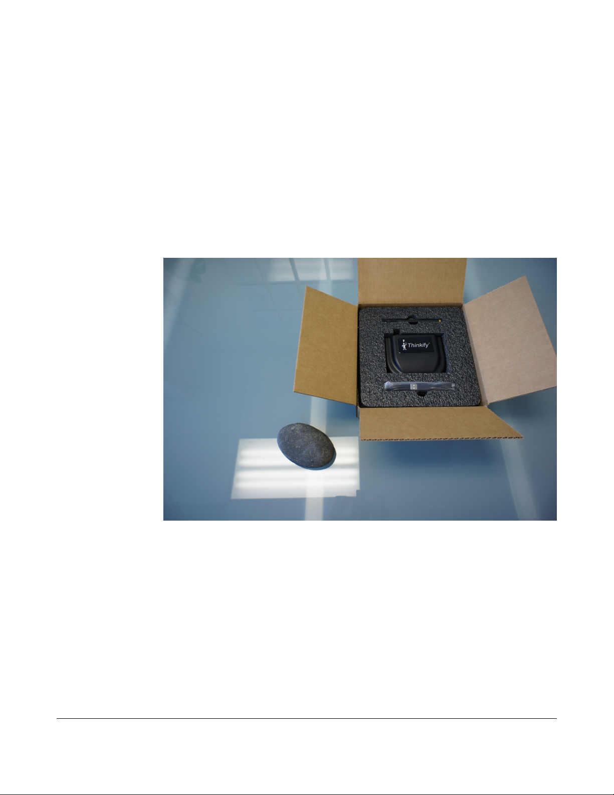
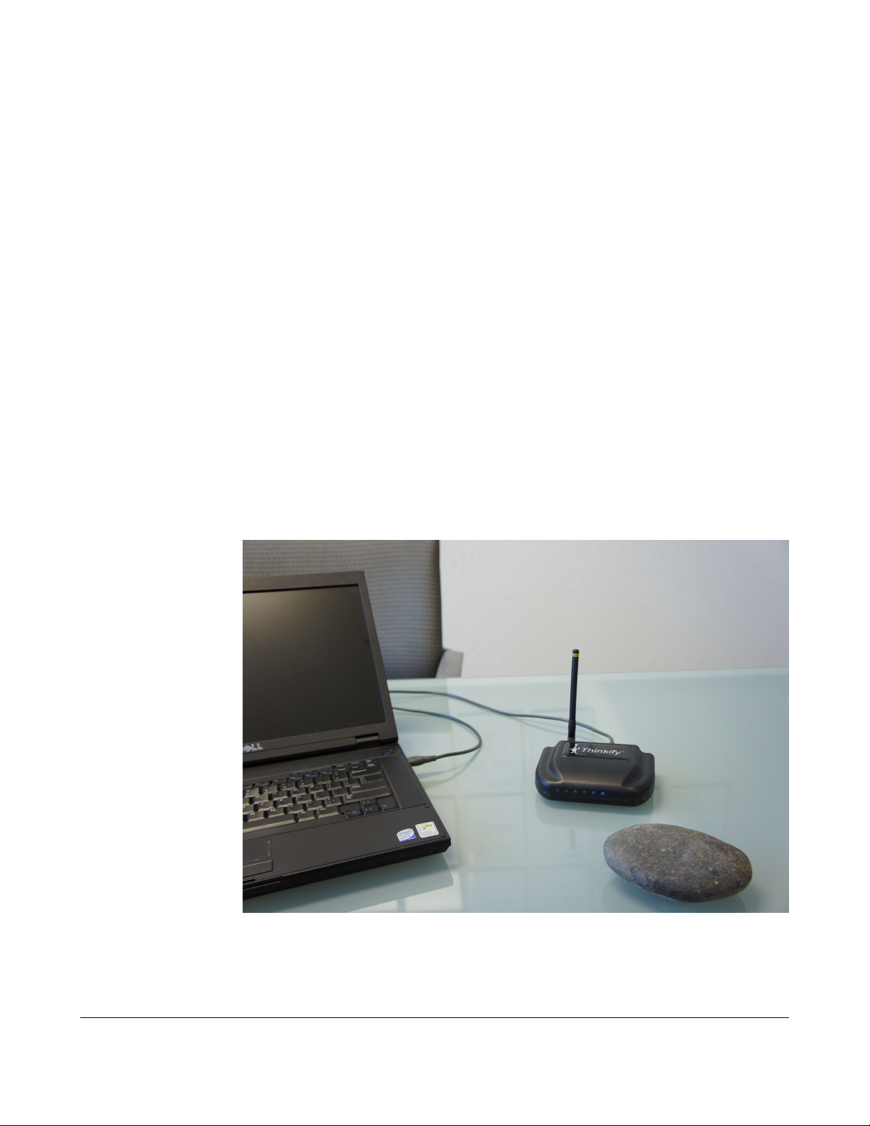
What's in the box?
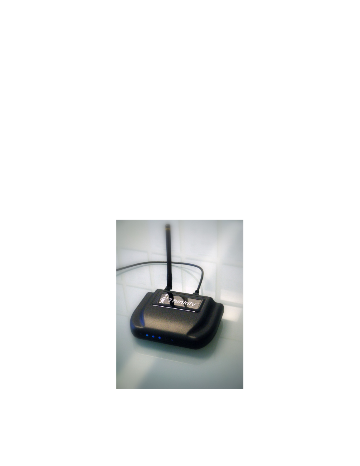
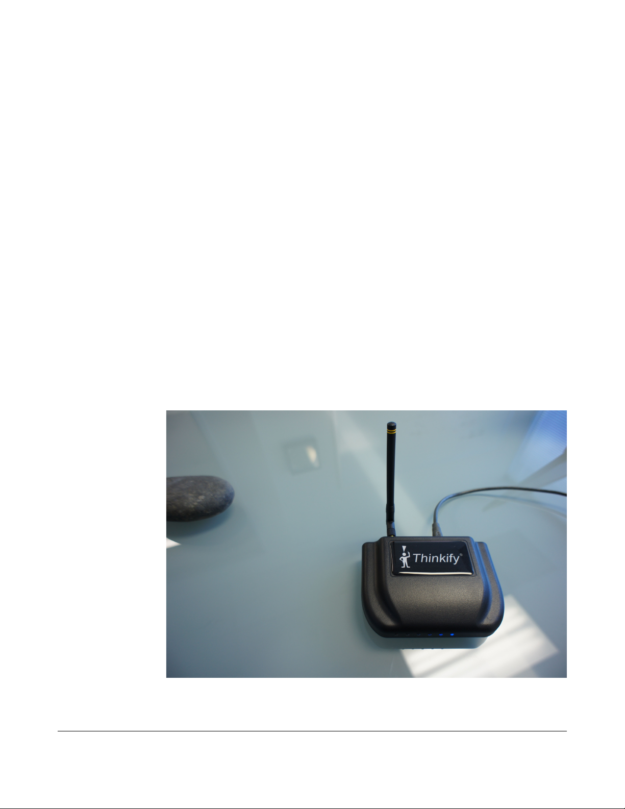
• A TR200 Desktop Reader
• An antenna
• A USB cable'
• A CD with this manual, software driver and demonstration program
• Some sample RFID Tags
Getting Started
(Stone not included.)
Hooking up the hardware
Attach the antenna to your reader. – It screws on.
Plug the USB cable into the reader and then into your laptop or PC.
You should see the blue LEDs on the front of the reader cycle through a start up pattern
and then the one should slowly blink to indicate that the unit has power and is waiting for
commands.
So much for hooking up the hardware... You're done.
The TR200 Desktop RFID Reader DCN-TF-01009 -007
8
Page 9
Setting up the Driver (Microsoft Windows)
Setting up the Driver (Microsoft Windows)
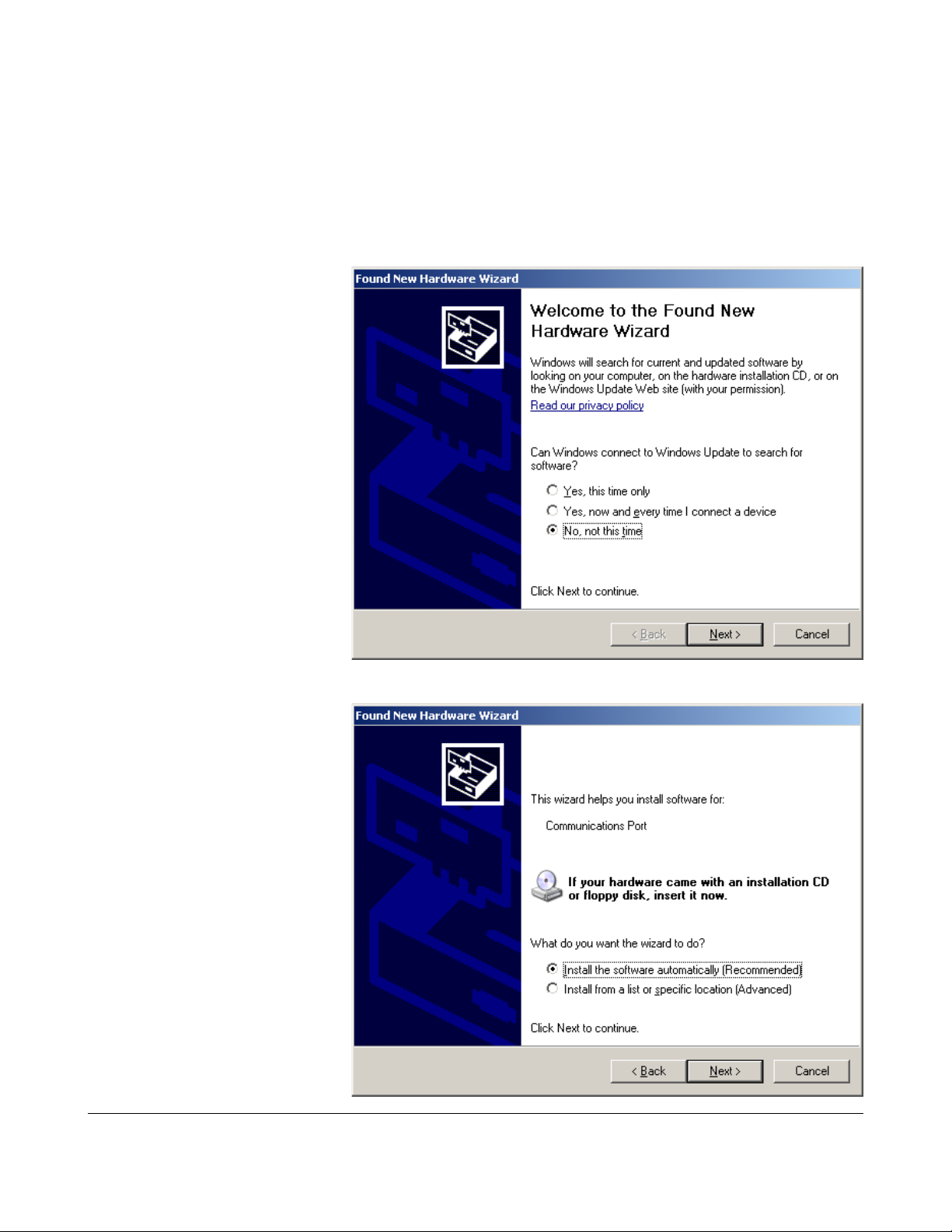
After you hook up the hardware, if you've never installed the driver software for the
reader on your computer you will see a message indicating that Windows doesn't know
about this device.
Under windows XP, the
message looks like this:
We're going to handle this
ourselves so select the
“No, not this time” option
and click “Next”.
In the following dialog
select “Install the software
automatically”. Insert the
CD and click “Next”.
(If you chose to have the
software install
automatically skip ahead.
Otherwise, a dialog will
appear where you can
select the “Include this
location in the search”
option and “Browse” to
the \inf directory on your
CD.)
The TR200 Desktop RFID Reader DCN-TF-01009 -007
9
Page 10
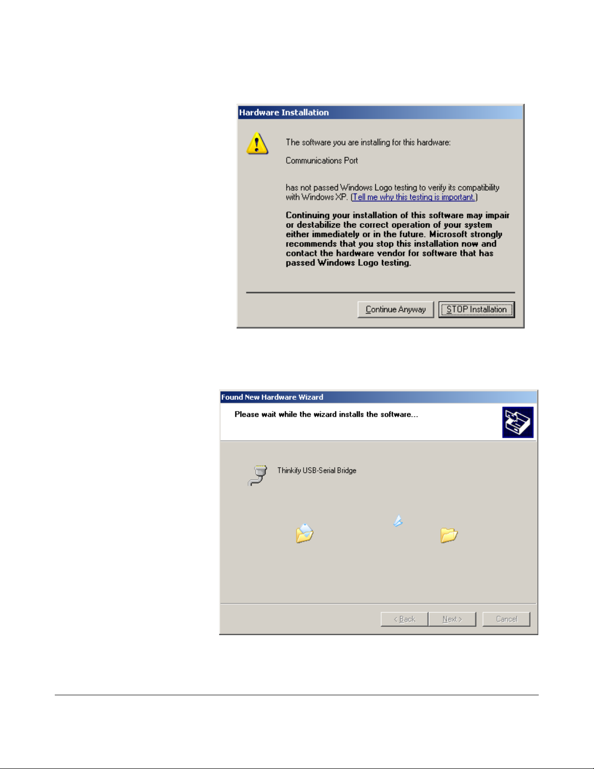
After clicking “Next” you'll get
a warning that the Thinkify
driver has not passed the
Microsoft Windows Logo
testing program.
We haven't.
In fact, we never even tried.
If you still trust us, click
“Continue Anyway”...
Setting up the Driver (Microsoft Windows)
The driver will now install.
Here we map the USB
you've plugged into to a
“virtual” serial port.
The TR200 Desktop RFID Reader DCN-TF-01009 -007
10
Page 11
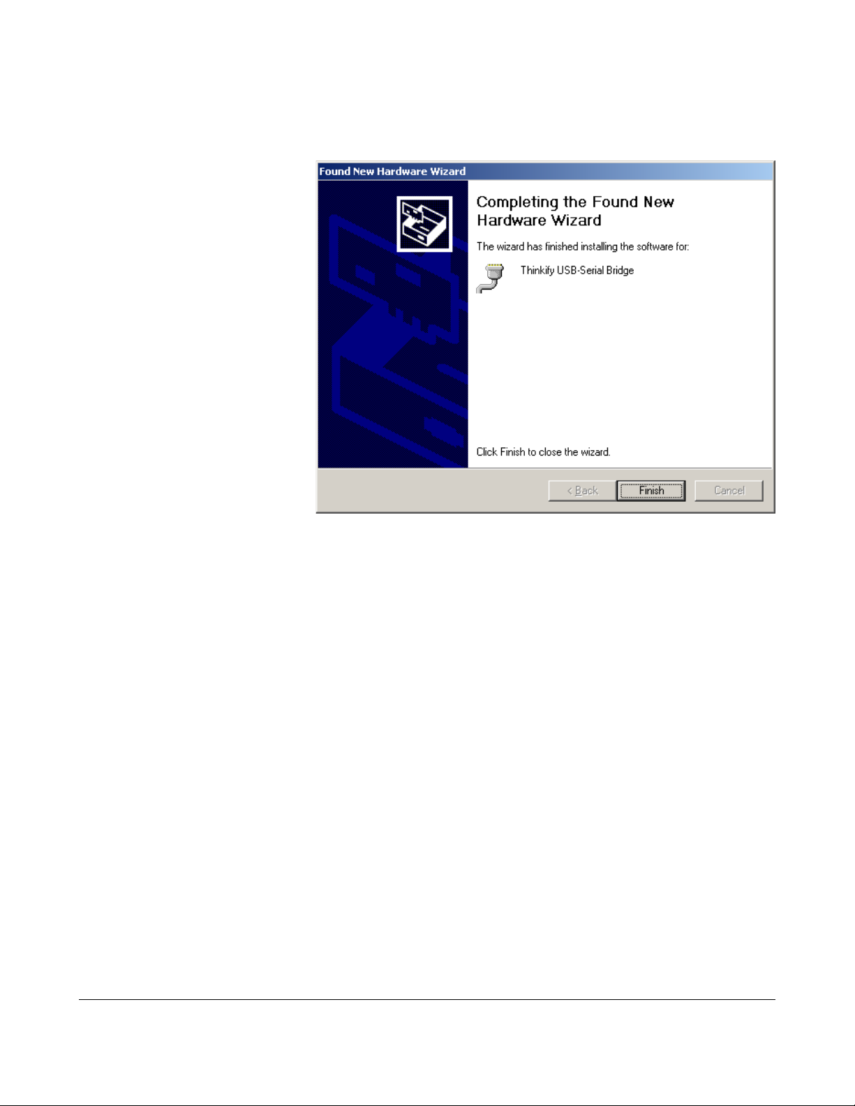
Setting up the Driver (Microsoft Windows)
If all goes well, you should see this screen. Click “Finish”
The driver is installed and your reader should be ready to use.
The TR200 Desktop RFID Reader DCN-TF-01009 -007
11
Page 12
Communicating with the Reader
Communicating with the Reader
Application software that talks to the TR200 opens up a connection on the virtual serial
port we enabled with our driver. We can test this interface with nearly any serial
communication program.
Most Windows systems we've encountered come with a serial communication program
called HyperTerminal installed under:
“Start/ All Programs /Accessories / Communications”
We will use HyperTerminal in our examples below.
A free, less buggy and far more capable serial communication program is Tera Term. In
addition to serial communication, Tera Term supports several network communication
standards including telnet and ssh. We recommend Tera Term for developers who want
to do more than casual explorations with HyperTerminal.
Tera Term is available for download at: http://ttssh2.sourceforge.jp/
The TR200 Desktop RFID Reader DCN-TF-01009 -007
12
Page 13
Communicating with the Reader
Determining your Com Port
Once the driver is installed, the next time you connect the reader to a USB port, it will be
recognized and given a virtual com port number. Each USB port you connect to will be
given a different number by default.
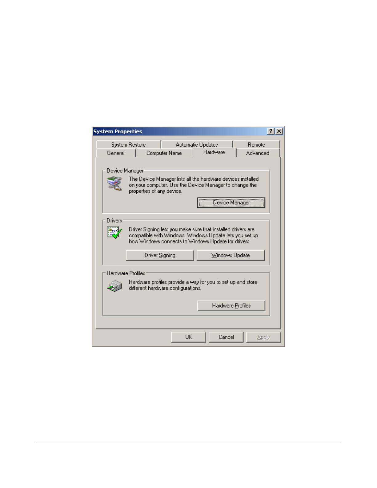
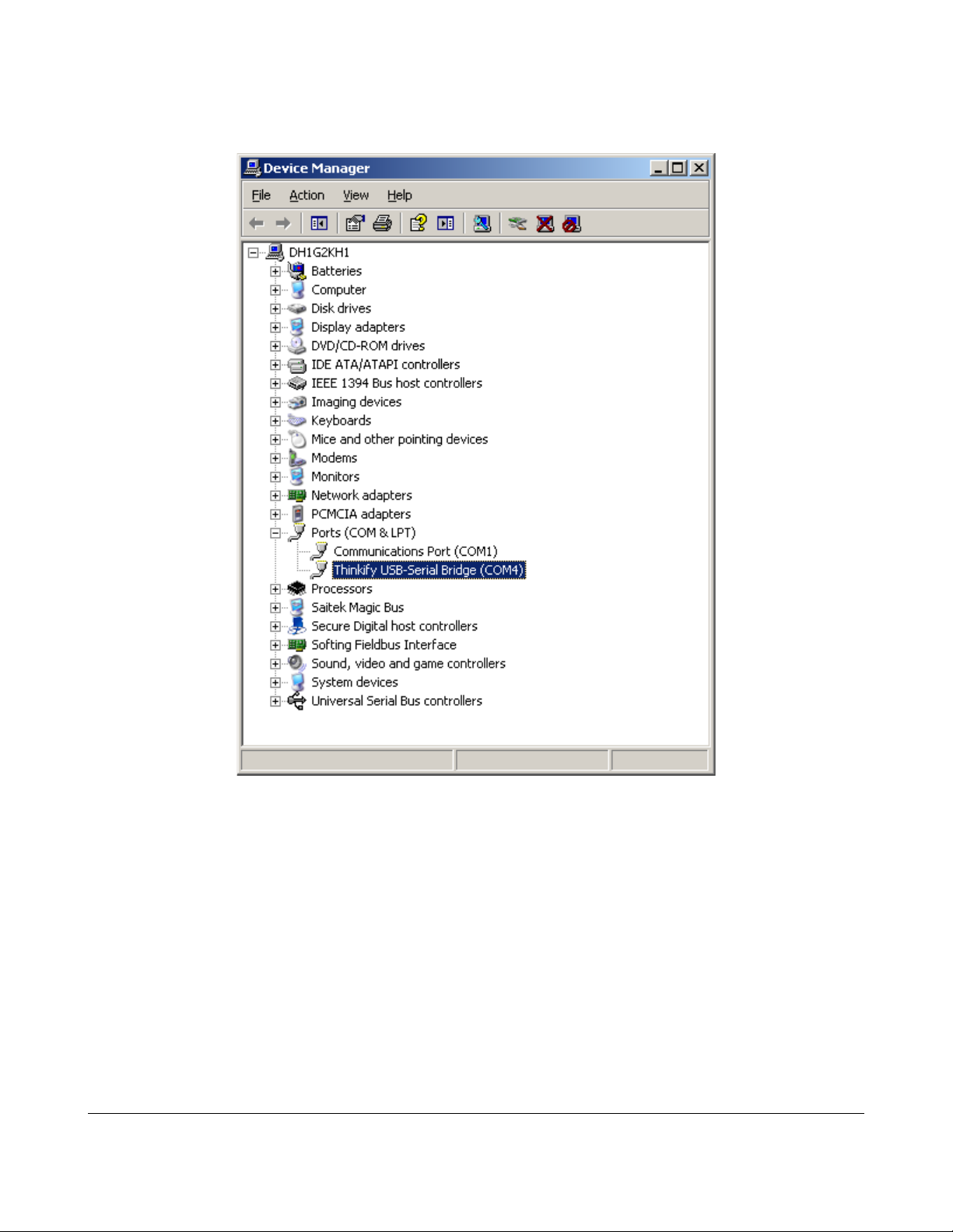
You can see the com port number you obtained by going to the Start / Control
Panel / System utility and click the Device Manager button in the hardware tab. See
below:
Click “Device Manager” and expand the “Ports (Com and LPT)” option. Look
for the Thinkify USB-Serial Bridge entry and note the com port.
The TR200 Desktop RFID Reader DCN-TF-01009 -007
13
Page 14
Communicating with the Reader
On my system it came up as COM4
*
You now know!
_______
*NOTE for advanced users using Windows XP: If you wish to change the com port number, you can by
right clicking on the entry for the Thinkify USB-Serial Bridge, selecting Properties, going to the Port
Settings Tab and clicking the Advanced button. The dialog window has a drop down list of available com
port names you may choose from.
The TR200 Desktop RFID Reader DCN-TF-01009 -007
14
Page 15
Communicating with the Reader
Using Hyperterminal
From the Start Menu, go to:
“Start /All Programs / Accessories / Communications”,
and launch HyperTerminal.
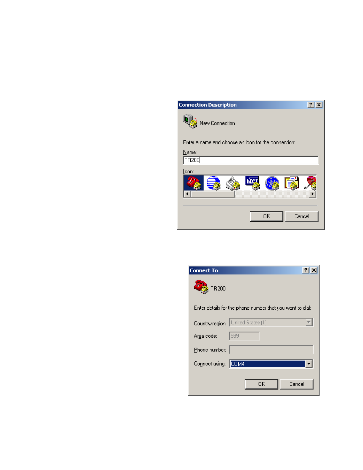
At the dialog box, create a new
connection for the TR200.
Pick the Com Port your reader is
connected to.
The TR200 Desktop RFID Reader DCN-TF-01009 -007
15
Page 16
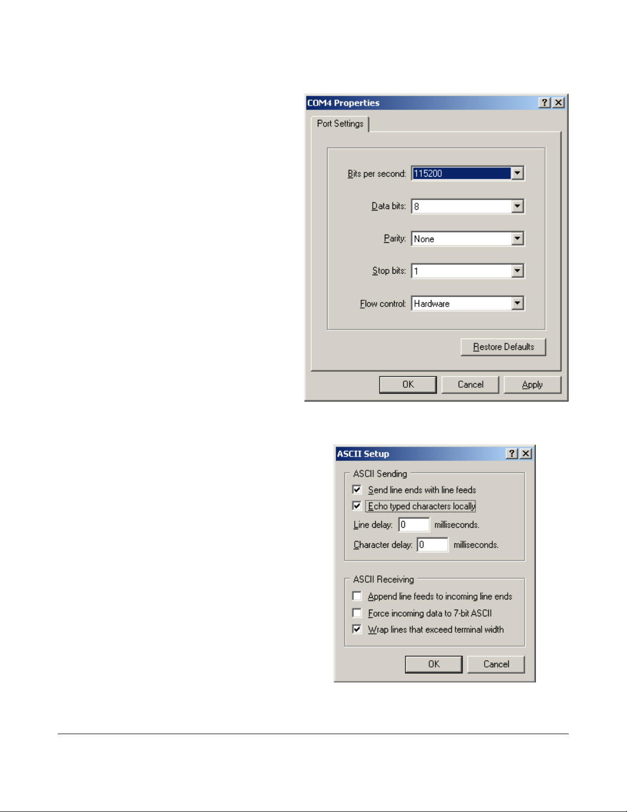
Set your communication parameters:
Communicating with the Reader
From the “File/Properties” Menu, select the “Settings” Tab and click Ascii
Setup.
Check “Send Line ends with line feeds” and
enable local echo so you can see the
commands you type.
Hit OK.
Congratulations! You're setup. Let's see if we're talking...
The TR200 Desktop RFID Reader DCN-TF-01009 -007
16
Page 17
Communicating with the Reader
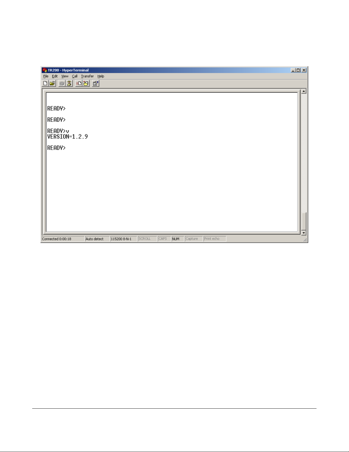
Hit enter a few times and type “v”[enter] to get the reader's firmware version.
You should see something like:
Your reader is alive and talking!
In the following sections, we describe the protocol structure and list the commands that
the reader can respond to using this interface. You can try out all the commands using
HyperTerminal to get a feeling for how they work. After that, you can use our software
APIs or roll your own to use the same commands from your own programs.
As an example, let's read some tags. Hold up your sample tags near the reader and
type “t”[enter] You should see something like this:
The TR200 Desktop RFID Reader DCN-TF-01009 -007
17
Page 18
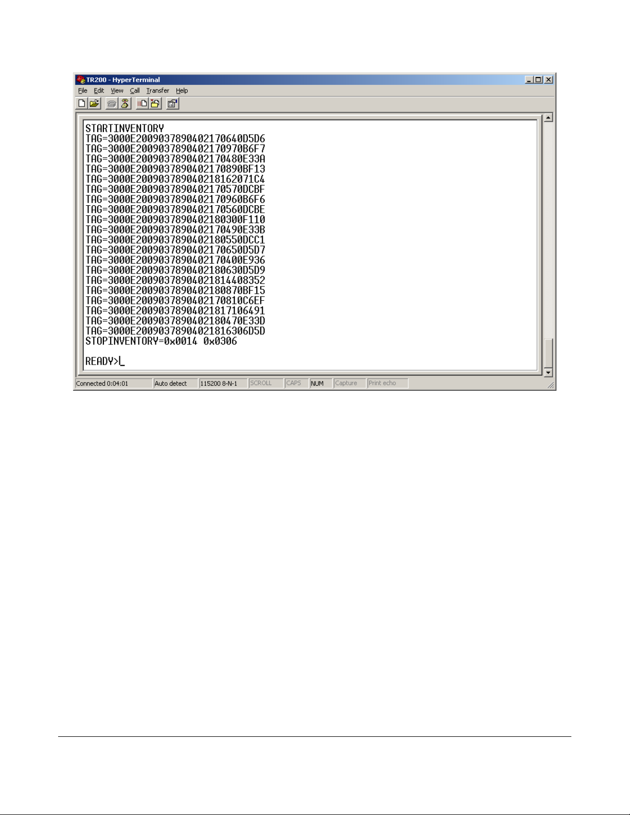
Communicating with the Reader
Victory!
The TR200 Desktop RFID Reader DCN-TF-01009 -007
18
Page 19

A Quick RFID Introduction
A Quick RFID Introduction
Class 1 Generation 2 (Gen2)
The RFID tags included in your reader kit conform to the UHF Class 1, Generation 2
standard maintained by EPC Global. (REF). EPC Global is a division of UPC – The
same standards organization that controls the barcode numbering system used on retail
packages. This standard (with minor changes) is also maintained by ISO under ISO18000-6-C. (REF)
Most Gen2 tags (as they are usually called) are Passive RFID devices. That is, they do
not require a battery and derive their power for operation from the RF field sent out by
the reader. This allows them to be small, inexpensive and operate virtually indefinitely.
Most Gen2 tags are also programmable devices. Users can put their own information
into the tags. The amount of data that can be stored depends on the type of tag but
hundreds of bits are typical. Data in the tag is organized into “Banks” of memory that
serve different functions under the protocol:
• Bank 0: Reserved Memory Kill and Access Password space.
• Bank 1: EPC Memory The unique tag identifier. Typically 128 bits. User
programmable. The Gen2 protocol is designed to extract this information quickly.
• Bank 2: TID Memory A factory programmed area that includes a serial number
and fields that describe the tag's capabilities.
• Bank 3: User Memory A programmable extended memory area for holding
additional information that is not the EPC. Not all tags support User Memory.
Gen2 tag memory can be “Locked” such that it cannot be changed without a passcode.
These locks can be reversible or permanent.
Finally, Gen2 tags can be rendered non-functional with a “Kill” command. Tags that are
killed cannot be recovered.
The TR200 Desktop RFID Reader DCN-TF-01009 -007
19
Page 20

Concepts (Performing an Inventory)
Concepts (Performing an Inventory)
Being an RFID reader trying to read multiple tags using the Gen2 protocol is sort of like
being a new teacher trying to take attendance in a kindergarten class... Sadly, the
administration didn't give you an attendance list on the first day of class so you have to
work it out for yourself.
Kindergarten Teacher RFID Reader
You have to get a list of everyone's
name
You have to get a list of all of the EPC codes
from the tags
Kids know their own names Tags have unique IDs in EPC memory they can
report
You can only hear one child at a time The reader can only process a signal from one
tag at a time
Kids want to all talk at once Multiple tags can respond at the same time
What both the reader and the teacher need is an anti-collision protocol – a way to keep
their respective tags/kids from talking at the same time.
Most teachers adopt an adult-talks-first protocol with a persistent state flag for whether a
child has been inventoried. This flag is maintained in the child. Sometimes there's a bidirectional exchange with an ACK/NAK option. Hey! that's a lot like Gen2.
“Huh?” You say.
Teacher: “Ok everyone! Quiet down. It's time to take attendance.” (Reader-talks-first)
Teacher: “Ok everyone! Hands up!” (Under Gen2 this is a Select command that
establishes who's going to participate in the inventory. – In this case, everyone. By
putting their hands up, the child has set a flag that indicates he/she hasn't been
inventoried, yet.)
Teacher: “When I point to you, tell me your first name.” (Granted this is a little contrived,
but it's a little like the Query command in Gen2 that kicks off an inventory sequence.)
The teacher randomly picks the first child, points to her and says, “You!”
Child: “Inga!” (In Gen2, a tag responds to a Query with a random number that is used in
the next command by the reader)
Teacher: “Inga who?” (This is like a Gen2 ACK (acknowledgment). It tells the tag/child
The TR200 Desktop RFID Reader DCN-TF-01009 -007
20
Page 21

Concepts (Performing an Inventory)
that the reader/teacher heard their response and is now asking them for their data.)
Child: “Svenson!”
Teacher:”You!” (Pointing to the next child. At this point, Inga assumes that the teacher
got her name, since she's moved on to the next child. She puts her hand down and sets
her state to “Inventoried”)
Child: “Mikey!”
Teacher: “Mikey who?”
Child: “Jones!”
Teacher: “Pardon me?” (If the reader doesn't understand the reply it can issue a NAK
and try again.)
Teacher: “Mikey who?”
Child: “Jones!”
Teacher: “You!” (On to the next child. Mikey puts his hand down, too.)
And off they go...
When the teacher reaches the end of the round, (See's no more raised hands in this
case) she's done.
This is clearly contrived and is an oversimplification of both the Teacher's real-life
protocol and Gen2, but it does captures some of the important features:
1. Inventories of the field need an anti-collision protocol to prevent multiple tags
from talking at the same time.
2. An inventory can begin with one or more Select commands that establish who
will participate in the inventory. (Teacher: “Ok, only the boys, put your hands up!”)
3. The state of whether or not a tag has been inventoried is maintained in the tag.
4. In the process of singulating a tag, the reader gets a handle (the child's first
name in the example above) that it can use for additional operations with that tag
(more on this below).
The analogy breaks down when you realize that unlike the teacher, the reader cannot
see the inventoried state of the tags (hands in the air). If the teacher tried to take
attendance of the class from behind a curtain, it would be a lot more difficult. Rather
than pointing at a child and saying, “You!” to keep them from talking at once, a different
protocol would be needed.
In Gen2, this is accomplished with the Query command. When the reader issues a
Query command, it includes in the message a parameter called Q that the tags use to
determine if they will respond immediately, or after some number of subsequent
The TR200 Desktop RFID Reader DCN-TF-01009 -007
21
Page 22

Concepts (Performing an Inventory)
QueryRep commands. The number of Query or QueryRep commands the tag will wait
to hear is determined randomly and can vary from 1 to 2^Q.
By adjusting the Q parameter used in its Query commands, the reader can prevent
multiple tags from responding simultaneously most of the time. If there is a collision, the
reader can adjust Q or just try again and let the tags roll a different random number.
From your perspective as a user of the reader, these details don't usually matter (we
adjust Q for you automatically) but they can be useful to know sometimes if you are
trying to optimize performance.
Concepts (Reading / Writing other data)
The Gen2 protocol is strongly oriented around the use case of rapidly reading the data
in Bank 1 of Memory (the EPC). In supply chain applications there can be hundreds of
tags moving past a read point and the reader needs to read them all as they go by.
Reading other data in other banks of memory or programming builds off of the protocol
we use for isolating tags and it extends it to allow a “conversation” to take place with a
tag we've isolated.
To read user memory for example, the reader first isolates a tag with an inventory and
then uses the handle from the tag as part of a sequence of commands to get the other
data. Writing is similar.
In the Thinkify reader, we allow you to specify a number of “Descriptors” that tell the
reader what additional actions (if any) to take when it reads a tag. Descriptors can be
used to Read additional memory areas, Write to memory, Lock and Unlock tag Memory
and Kill tags.
This is a very powerful approach. By using Select commands (a.k.a. Masking) as part of
the inventory we can quickly specify that we are interested in performing an operation on
just one, some or all of the tags present in front of the reader.
The TR200 Desktop RFID Reader DCN-TF-01009 -007
22
Page 23

Thinkify Reader Protocol Overview
Thinkify Reader Protocol Overview
Here we give an overview of the Thinkify Reader Protocol message structure and
provide a high-level summary of the major command groups available to the user.
The Thinkify Reader Protocol (TRP) is a human-readable ASCII protocol that allows
users and applications to set parameters for RF control, tag list acquisition, tag
programming and digital I/O behavior. The TRP may also be used to acquire data from
the reader and be notified of tag read events, I/O events and reader status.
The TRP is used across all Thinkify reader products and supported hardware interfaces
including; RS232, USB and Ethernet.
Command Structure
The Thinkify Reader Protocol uses a Command-Response model. --Communication is
initiated by the Host and the Reader responds with an acknowledgment or data.
Users may interact with the reader from a terminal program or their own software using
the Thinkify APIs. All that is required is that they send strings to the device over an
active connection and terminate messages correctly. Replies will be sent back, often on
multiple lines, terminated by a “READY>” prompt.
Host Commands
Host commands to the Reader are ASCII strings terminated with a Carriage Return.
Valid command messages are composed of numeric characters in the range of 0-9
(0x30 to 0x39) ASCII characters in the range of a..Z (0x to 0x) and the carriage return
character (0x0D).
Line feed characters are ignored by the reader and may be sent without effect. --The
Reader does not echo commands back to the Host.
The general format of a Host to Reader message is:
<COMMAND>[<SUBCOMMAND>[<PARAM1>][<...>][<PARAMn>]]<CR>
(Here [] denotes an element that may be optional.)
• <COMMAND> is typically a single character.
• <SUBCOMMAND> is typically a single character
• <PARAMs> vary in length and depend on the command being sent. (See details
below). There are no spaces between parameters if multiple parameters are
sent as part of a message.
The TR200 Desktop RFID Reader DCN-TF-01009 -007
23
Page 24

Command Structure
• <CR> is the Carriage Return CR character (0x0D). Upon receipt of a carriage
return, the Reader will attempt to parse the command message and execute the
command if properly formatted.
Reader Replies
Reader replies to Host commands are also ASCII strings. Replies may be either a single
line or a multi-line reply, depending on the Command. Each line of a reply is terminated
with a Carriage Return + Line Feed character pair, CRLF (0x0D,0x0A)
When the reader has finished sending all data back to the host in response to the
command, it will end the sequence with a “READY>” prompt, indicating is prepared to
process another message. Generally, after sending a Command, the Host should not
send a new command until it sees the "READY>" message.
The general format of a Reader to Host message is:
[STARTMSG<CRLF>]
<Line1><CRLF>
<Line2><CRLF>
…
<Linen><CRLF>
[STOPMSG<CRLF>]
<CRLF>
<READYPROMPT>
(Here [] denotes an element that may be optional.)
• [STARTMSG] – Indicates the beginning of command processing. – Not sent on
every command. Sent on commands where inventories are performed.
• <Lines> – Data sent back in response to the command
• [STOPMSG] – Indicates command processing is finished. – Not sent on every
command. Send on commands where inventories are performed.
• <READYPROMPT> – “READY>” prompt. Indicates that the reader is ready to
accept another command.
Special Case: Inventory Replies
When the Reader performs a T or Tn command that is setup for infinite repeat, it will
stream line data until it sees a character from the host. It will then terminate the
message with the STOPMSG and READYPROMPT. (See T commands below for
examples and discussion.)
The TR200 Desktop RFID Reader DCN-TF-01009 -007
24
Page 25

Command Structure
Examples
Example – To set the General Purpose Output (GPO) Pin 1 to a High Level
<COMMAND=”G”><SUBCOMMAND=”1”><PARAM1=”1”><TERM=0x0D>
The Host would have to send the string:
G11<CR>
The Reader would respond with:
GPOUTPUT1=1<CRLF>
READY>
Example: – Read Tags using the “T” command.
<COMMAND=”T”>
Host:
T<CR>
Reader:
STARTINVENTORY<CRLF>
TAG=3000100000000000000000003560<CRLF>
TAG=3000100000000000000000003568<CRLF>
TAG=300010011002100310041007BBBB<CRLF>
TAG=3000100000000000000000003583<CRLF>
TAG=3000100000000000000000003556<CRLF>
TAG=3000100000000000000000003569<CRLF>
TAG=3000100000000000000000003557<CRLF>
TAG=3000BBAA99887766554433221100<CRLF>
TAG=3000100000000000000000003582<CRLF>
STOPINVENTORY=0x0009 0x00EA<CRLF>
<CRLF>
READY>
Example – Query the Inventory Parameter Settings
<COMMAND=”I”>
Host:
I<CR>
The TR200 Desktop RFID Reader DCN-TF-01009 -007
25
Page 26

Command Structure
Reader:
SELTYPE=1<CRLF>
SESSION=1<CRLF>
TARGET=0<CRLF>
Q=0x3<CRLF>
OUTERLOOP=0x01<CRLF>
INNERLOOP=0x03<CRLF>
SELECTLOOP=0x1<CRLF>
<CRLF>
READY><CRLF>
Example: --Tn command
Tn (T1, T2, ...T6) commands repeatedly perform inventories until interrupted by the
Host. During this time the Reader will stream tag data until a character is received from
the Host. The reader will then stop the Inventory sequence and terminate the reply.
Host:
T6<CR>
Reader:
STARTINVENTORY<CRLF>
TAG=3000100000000000000000003582 911750 07 8 9 Q E468<CRLF>
TAG=3000100000000000000000003557 911750 04 8 9 I E471<CRLF>
TAG=3000100000000000000000003583 911750 06 8 9 Q E47C<CRLF>
TAG=3000100000000000000000003557 911750 02 8 9 I E486<CRLF>
TAG=3000100000000000000000003557 911750 06 8 9 I E493<CRLF>
TAG=3000100000000000000000003568 911750 02 8 9 Q E49D<CRLF>
TAG=3000100000000000000000003557 911750 07 9 A I E4A9<CRLF>
TAG=3000BBAA99887766554433221100 911750 02 9 A Q E4B4<CRLF>
TAG=3000100000000000000000003556 911750 07 7 0 I E4C3<CRLF>
TAG=3000100000000000000000003557 911750 00 7 0 Q E4D3<CRLF>
TAG=3000100000000000000000003557 911750 05 7 0 Q E4DD<CRLF>
TAG=3000100000000000000000003569 911750 06 7 0 I E4ED<CRLF>
TAG=3000100000000000000000003583 911750 04 7 0 I E4F5<CRLF>
TAG=3000100000000000000000003560 911750 02 7 0 Q E4FD<CRLF>
TAG=3000100000000000000000003557 911750 00 7 0 Q E506<CRLF>
Character (space) received from the Host!
TAG=3000100000000000000000003569 911750 07 7 1 I E511<CRLF>
TAG=3000100000000000000000003557 911750 01 7 1 Q E51C<CRLF>
STOPINVENTORY=0x0011 0x00C6<CRLF>
<CRLF>
READY><CRLF>
The TR200 Desktop RFID Reader DCN-TF-01009 -007
26
Page 27

Command Groups
Command Groups
Commands are grouped into five major areas: functions for working with RFID tags,
functions for controlling the reader's radio subsystem, functions for interacting with the
reader's GPIO port, system commands for firmware updates, etc., and advanced
engineering functions used mostly for regulatory testing and by users wishing to develop
custom OEM solutions.
Tag Commands
GPIO and Triggering
Radio Control Commands
System Commands
Engineering Test Functions
The TR200 Desktop RFID Reader DCN-TF-01009 -007
27
Page 28

Command Reference
Command Reference
Summary
A quick overview of the main command groups follow. Detailed explanations are in the
following sections.
Main
Command
A RX Amplifier Control Engineering / Test
B Enter Bootloader System
C Low-Level Chip Registers Engineering / Test
D Diagnostic Functions Engineering / Test
F RX Filter Control Engineering / Test
G GPIO Control GPIO Control and Triggering
I Inventory Control Tag Commands
K Kill / Access Data Descriptors Tag Commands
L Low-Level Tests Engineering / Test
M Tag Masking Tag Commands
Description Command
Group
P Protocol Air Interface Radio Control
R RF Control Radio Control
S Status Functions System
T Perform Tag Inventory Tag Commands
V Get Firmware Version (Read Only) System
X eXtra Read / Write Data Descriptors Tag Commands
The TR200 Desktop RFID Reader DCN-TF-01009 -007
28
Page 29

"A" RX Amplifier Control
"A" RX Amplifier Control
Description
The “A” command and sub-commands are used to set and get the parameters that
control the characteristics of the amplifier in the base band receiver.
Command Group
Engineering / Test
Command
<A>[<SUBCMD>[<PARAMS>]]
Sub-Commands
Sub
Command Description
AA 8 dB mixer attenuation control. – Off or On. 0..1
AG Gain adjustment:
Value Gain
0 0dB
1 -9dB
2 -6dB
3 -3dB
4 +3dB
5 +6dB
6 +9dB
Legal Values
for SET
0..6
AH Hysteresis: 7 steps of 3dB ea. 0..7
AM 10 dB mixer amplification control. Off or On. 0..1
The TR200 Desktop RFID Reader DCN-TF-01009 -007
29
Page 30

“A” Command Examples
Get All Settings
READY>a
INPUTATTEN=1
GAIN=-0
HYSTERESIS=0
MIXERBOOST=0
READY>
Set the Gain
READY>ag2
GAIN=-6
READY>\
"A" RX Amplifier Control
The TR200 Desktop RFID Reader DCN-TF-01009 -007
30
Page 31

"BOOTLOADER" – Enter Bootloader
"BOOTLOADER" – Enter Bootloader
Description
Places the reader in a special mode where it is waiting to receive a firmware upgrade. In
this state, the reader will not respond to normal commands and requires a power cycle
to return to normal operation. See Appendix A for how to upload firmware using the
Thinkify Upgrade Utility.
Note
Entering bootloader mode un-enumerates the USB port in Windows. Reset into normal
code re-enumerates port.
This can confuse terminal programs like Tera Term / Hyperterm. After executing the
bootloader command disconnect terminal program. After resetting and re-enum then
reconnect terminal program.
The host Bootloader program provided by Thinkify for firmware upgrades runs the USB
interface with a HID windows class driver. (Normal operation is with a windows CDC
class driver.)
Command Group
System
Command
<BOOTLOADER><CR>
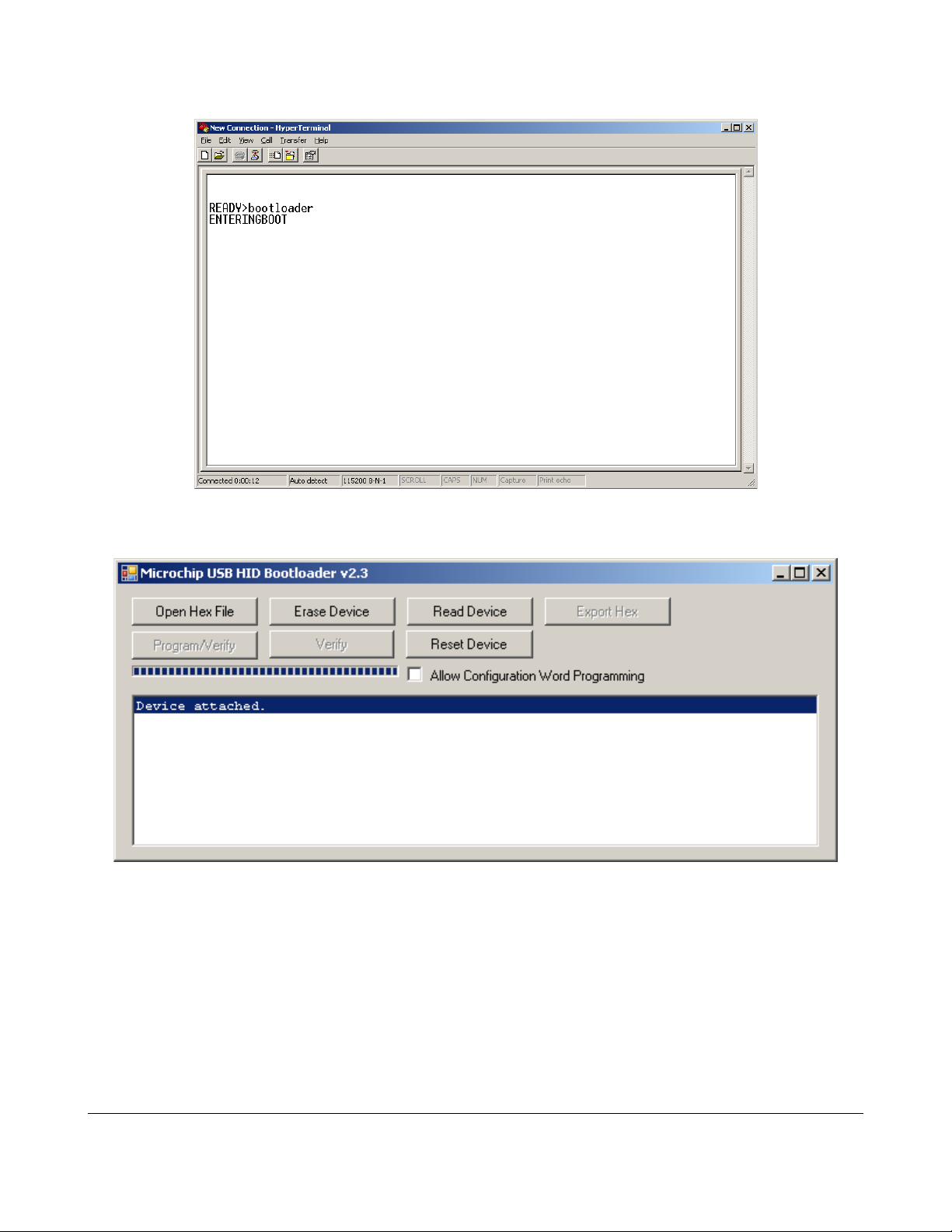
“Bootloader” Example
READY>bootloader
ENTERINGBOOT
The reader is now waiting for a firmware upgrade. At this point you may use the Thinkify
Upgrade Utility to load new firmware. See Appendix A.
The TR200 Desktop RFID Reader DCN-TF-01009 -007
31
Page 32

"C" Low-Level Chip Control Registers
"C" Low-Level Chip Control Registers
Description
The “C” command and sub-commands are used to set and get the low-level control
registers in the AM3392 chip. (An engineering command.)
Command Group
Engineering / Test
Command
<C>[<SUBCMD>[<PARAMS>]] – see table.
<C><ADDR><VAL> – sets a register. ADDR may be one or two nibbles. VAL
may be 2 or 6 nibbles.
Sub-Commands
Sub
Command Description
C Report all registers
Register Description
0x00 Status control (byte)
0x01 Protocol control (byte)
0x02 TX option (byte)
0x03 RX option (byte)
0x04 TRcal Low reg (byte)
0x05 TRCal Hi reg (byte)
0x06 TX Delay (byte)
0x07 RX No Resp Wait (byte)
Legal Values
for SET
-
0x08 RX Wait (T1) (byte)
The TR200 Desktop RFID Reader DCN-TF-01009 -007
32
Page 33

"C" Low-Level Chip Control Registers
Sub
Command Description
Register Description
0x09 RX Filt Reg (byte)
0x0A RX Spec2 (byte)
0x0B Regulator and RF control (byte)
0x0C -
0x0D IRQ Mask (byte)
0x0E
0x0F
0x10
Legal Values
for SET
0x11 Test Select Reg (byte)
0x12 Test Setting reg (word)
0x13
0x14 CLSYS ANAOUT (word)
0x15 MOD control (word)
0x16 PLL main control (word)
0x17 PLL aux control (word)
0x18 DAC reg (byte)
0x19
0x1A RXLen1 (byte)
0x1B RXLen2 (byte)
0x1C
The TR200 Desktop RFID Reader DCN-TF-01009 -007
33
Page 34

"C" Low-Level Chip Control Registers
Sub
Command Description
Register Description
0x1D TXLEN1 (byte)
0x1E TXLEN2 (byte)
CS Report all shadow registers -
CR Resets all registers to program default. -
Legal Values
for SET
The TR200 Desktop RFID Reader DCN-TF-01009 -007
34
Page 35

“C” Command Examples
Get all values:
READY>c
REG00=0x20
REG01=0x4D
REG02=0xE1
REG03=0x92
REG04=0x41
REG05=0xC3
REG06=0x00
REG07=0x05
REG08=0x03
REG09=0x37
REG0A=0x81
REG0B=0x58
REG0C=0x00
REG0D=0x3F
REG0E=0x03
REG0F=0x00
REG10=0x78
REG11=0x00
REG12=0x00004000
REG13=0x51
REG14=0x00008413
REG15=0x00403F06
REG16=0x0064A907
REG17=0x00011846
REG18=0x00
REG19=0x00
REG1A=0x00
REG1B=0x00
REG1C=0x00
REG1D=0x00
REG1E=0x00
"C" Low-Level Chip Control Registers
READY>
The TR200 Desktop RFID Reader DCN-TF-01009 -007
35
Page 36

“D”- Diagnostic Functions
“D”- Diagnostic Functions
Description
The D command and sub-commands are used to control Scope triggers and pulses
coming directly from the AM chip. These may be used in troubleshooting and regulatory
testing. (An Engineering function.)
Command Group
Engineering / Test
Command
<D>[<SUBCMD>[<PARAMS>]]
Sub-Commands
Sub
Command Description
DT Set Inventory Parameters to Default Values
0 = No Trigger
1 = Trigger when a SELECT command is sent
2 = Trigger when a QUERY command is sent
3 = Trigger when a ACK command is sent
4 = Trigger when a REQRN command is sent
5 = Trigger when a READ command is sent
DD Sends a direct command out the IC. (no Get)
Values a mystery --known only to the Dark Code Lord.
“D” Command Examples
GET and SET
READY>dt
SCOPETRIGGER=0x00
Legal Values
for SET
0..5
0..FF?
READY>dt4
SCOPETRIGGER=0x04
READY>
The TR200 Desktop RFID Reader DCN-TF-01009 -007
36
Page 37

"F" RX Filter Control
"F" RX Filter Control
Description
The F command and sub-commands are used to control the RX baseband filter. These
commands may be used in troubleshooting and regulatory testing. (An Engineering test
function.)
Command Group
Engineering / Test
Command
<F>[<SUBCMD>[<PARAMS>]]
Sub-Commands
Sub
Description Legal Values
Command
F Report current filter settings. -
FH Hi Pass value 0..7
FL Low Pass Value 0..7
FB By Pass Filter
Bit 0 = 40 KHz
Bit 1 = 160 KHz
FS AC Speedup 0..1
for SET
0..3
The TR200 Desktop RFID Reader DCN-TF-01009 -007
37
Page 38

“F” Command Examples
GET and SET
READY>f
FILTER PARAMS
LOWPASS=6
HIGHPASS=7
BYPASS160=0
BYPASS40=0
ACSPEEDUP=0
READY>fl5
LOWPASS=5
"F" RX Filter Control
The TR200 Desktop RFID Reader DCN-TF-01009 -007
38
Page 39

"G" GPIO Settings
"G" GPIO Settings
Description
The G command and sub-commands are used to control the GPIO port. These may be
used to set/retrieve GPIO pin settings or to set the reader up for triggered reading.
Using the GT command, the reader may be configured to read tags in any of the
supported inventory modes for either a fixed time after an edge transition or while a pin
is held in a particular state.
Command Group
GPIO Control and Triggering
Command
<G>[<SUBCMD>[<PARAMS>]]
Sub-Commands
Sub
Command
G Reports current state of input and output lines -
G0 Write Output Port 0 (no Get) 0..1
G1 Write Output Port 1 (no Get) 0..1
GT Triggering setup for Autonomous Reading
Description Legal
GT<port (nibble)> <active (nibble)> [<type
(nibble)> <action (nibble)> <time (byte)> (if
active)]
<TYPE (0= posedge, 1 = negedge, 2= poslevel, 3
neglevel)>
Values for
SET
See
Description
<ACTION (0 = T3, 1= T4, 2 = T5, 3 = T6, 4 = T)>
<TIME (if edge only - range 0x01 to 0xFF in .1sec
units for .1 to 25.5 seconds)>
The TR200 Desktop RFID Reader DCN-TF-01009 -007
39
Page 40

"G" GPIO Settings
“G” Command Examples
GET and SET
//Get the current settings
READY>g
GPINPUT0=1
GPINPUT1=0
GPOUTPUT0=0
GPOUTPUT1=0
//Get Trigger Settings
READY>gt
TRIGGERTYPE=DISABLED
//Configure for edge trigger on port 1 for 10 seconds (0x0A seconds)
READY>gt11040a
TRIGGERTYPE=POSEDGE PORT1
TRIGGERACTION=T 0A
READY>
The TR200 Desktop RFID Reader DCN-TF-01009 -007
40
Page 41

“I”- Inventory Control
“I”- Inventory Control
Description
The I command and sub-commands are used to set and get the parameters that control
the flow of the Gen2 anti-collision algorithm. Modifications to the default parameters may
be helpful in cases where there are a large number of tags in the field or when it is
desirable to increase the number of redundant reads for a given tag.
Command Group
Tag Commands
Command
<I>[<SUBCMD>[<PARAMS>]]
Sub-Commands
Sub
Command Description
ID Set Inventory Parameters to Default Values -
II Inner Loop Count: Each INNERLOOP runs a tag
acquisition STATEMACHINE
IL Gen2 SEL Flag: Value used in QUERY for the SEL field.
See G2 spec. (Usually set to 0)
IO Outer Loop Count: Number of FULL INVENTORY
ITERATIONS (one iteration is a SELECT group and a
INNER LOOP group)
IQ Gen2 Q Parameter: The Q used in the QUERY that
starts the round
IS Gen2 Session: The session (0 to 3) that will be used for
the entire inventory run.
Legal Values
for SET
0..FF
0..3
0..FF
0..8
0..3
IT Inventory Target: Defines whether the QUERY that
0..1
initiate round is looking for tags in the A or B state
The TR200 Desktop RFID Reader DCN-TF-01009 -007
41
Page 42

“I”- Inventory Control
Sub
Command Description
IW Select Count: Number of times SELECT function is
executed - each execution sends every MASK that is
enabled
IX Append XPC Data Flag 0..1
Legal Values
for SET
0..F
The TR200 Desktop RFID Reader DCN-TF-01009 -007
42
Page 43

“I” Command Examples
GET
//Get all parameters
READY>i
INVENTORY PARAMS
SELTYPE=1
SESSION=1
TARGET=0
Q=0x3
OUTERLOOP=0x01
INNERLOOP=0x03
SELECTLOOP=0x1
//Get just the Q value
READY>iq
Q=0x3
READY>
“I”- Inventory Control
SET
//Set some values
READY>iq3
Q=0x3
READY>ii4
INNERLOOP=0x04
//Set it up to read until interrupted. OuterLoop = 0xFF
READY>ioff
OUTERLOOP=0xFF
READY>
The TR200 Desktop RFID Reader DCN-TF-01009 -007
43
Page 44

"K" Kill – Lock – Access Descriptors
"K" Kill – Lock – Access Descriptors
Description
The K family of commands are used to control lock kill and access command behavior.
The K commands allow the user to get/set passwords used in kill, lock and access
operation and specify lock type for the lock commands.
These commands are described in detail in the EPC Global C1G2 specification: uhf
c1g2_standard- version 1.2.0.pdf
Command Group
Tag Commands
Command
<K>[<SUBCMD>[<PARAMS>]]
Sub-Commands
Sub
Command
KA Get / Set ACCESS Password
KAR Clears ACCESS Password -
KL Get / Set Lock Descriptor
Description Legal Values
KA for get
KA<ACCESSPASSWORD> for set.
Options:
KL – Report Lock Descriptor
KL<active 1:0> - (De)Activate Lock
descriptor
KL<active 1:0><LOCKBITS (20 bits in 5 ASCII
HEX nibbles)> De)Activate Lock descriptor
and Set LOCK value
for SET
32 Bits from 8
Nibbles
See
Description
KK Controls KILL descriptor
KK report KILL descriptor
KK<active 1:0> activate or de-activate the
KILL descriptor
The TR200 Desktop RFID Reader DCN-TF-01009 -007
44
See
Description
Page 45

"K" Kill – Lock – Access Descriptors
KK<active 1:0><KILLPASSWORD (16 bit 4 ASCII
HEX nibbles)> = activate or de-activate the
KILL descriptor and setup KILL password val
The TR200 Desktop RFID Reader DCN-TF-01009 -007
45
Page 46

“K” Command Examples
GET
READY>ka
ACCESSPASSWORD=00000000
READY>kk
ACTIVE=0
KILLPASSWORD=00000000
READY>kl
ACTIVE=0
LOCKBITS=00000
//Set the LOCK active
READY>kl1
ACTIVE=1
LOCKBITS=00000
"K" Kill – Lock – Access Descriptors
The TR200 Desktop RFID Reader DCN-TF-01009 -007
46
Page 47

"L" Low-Level Tests
"L" Low-Level Tests
Description
The LF command and sub-commands are used to monitor read performance for a single
tag across frequency. (An engineering test function.)
Command Group
Engineering / Test
Command
<L>[<SUBCMD>[<PARAMS>]]
Sub-Commands
Sub
Description Legal Values
Command
LFQ Reports number of responses to a Query as a
function of frequency. (100 Max)
LFD Reports values of the reflected power mixers v.
frequency.
LFA Reports Queries, ACKS and reflected power. -
for SET
-
-
The TR200 Desktop RFID Reader DCN-TF-01009 -007
47
Page 48

“L” Command Examples
DO (no get or set)
//Perform a Scan
//Frequency Queries Acks Irefl Qrefl
READY>lfa
902750 100 100 172 157
903250 100 100 172 155
903750 100 100 172 153
…..
925750 99 99 138 131
926250 90 81 138 132
926750 81 59 138 132
927250 99 89 138 133
READY>
"L" Low-Level Tests
The TR200 Desktop RFID Reader DCN-TF-01009 -007
48
Page 49

“M" MASK / SELECT control
“M" MASK / SELECT control
Description
As mentioned in the introductory sections, an inventory may begin with the issuance of
one or more Gen2 Select commands to determine which tags participate in the inventory
round.
When the Select loop runs (see the IW command) each pass through the loop can issue
up to four (4) independent Select commands. The parameters associated with these
Select commands are stored in the reader's Masks list.
When the Select is sent, the ACTIVE flag of each of the four (4) masks is examined in
order from 0 to 3. If ACTIVE == 1 the MASK is used to structure the Select command.
From a RESET, MASK0 is active (ACTIVE FLAG 1) with a ACTION of 000 (ALL TAGS to
A state – see G2 spec TABLE6.19 for the 8 possible ACTIONS) and a LEN of 0×00. This
means “All tags selected”.
From a RESET, MASK1, MASK2, MASK3 are set to INACTIVE (ACTIVE FLAG == 0)
Command Group
Tag Commands
Command
<M><SUBCMD><MASKNUM><PARAMS>
Sub-Commands
Sub
Command
MA Set Mask Parameters to Default Values. – Will put all masks to their
defaults from a RESET state.
M Command
<M><MASKNUM (0 to 3)>
will GET the values of the requested MASK
Description
M Command
The TR200 Desktop RFID Reader DCN-TF-01009 -007
49
Page 50

“M" MASK / SELECT control
Sub
Command
Description
<M><MASKNUM (0 to 3)><PARAMS>
will PUT a MASK into MASKNUM
<PARAMS>
<ACTIVE (0 or 1)>
0 means inactive, 1 means active
<TTYPE (0 or 1)>
0 means use the current Session (See: IS command)
1 means use SL 100 flag.
<ACTION (0 to 7)>
TODO: Expand this section. – Until we do, we recommend you see
the EPC Global G2 Spec TABLE 6.19 for the 8 possible ACTIONS.
http://www.epcglobalinc.org/standards/uhfc1g2/uhfc1g2_1_2_0standard-20080511.pdf
<MEMBANK (0 to 3)>
see G2 spec
<LEN byte>
Number of BITS in mask
<EBVBANK byte(s) (min 1 byte, max 4)>
This is a BIT pointer see annexA G2 spec EBV
pointers
<MASK byte(s) (min 0, max 32 bytes)>
Must have enough bytes to meet LEN. All bits are LEFT justified i.e
MSB of BYTE0 is first bit of mask MSB of BYTE1 is 8th of mask etc.
The TR200 Desktop RFID Reader DCN-TF-01009 -007
50
Page 51

“M" MASK / SELECT control
“M” Command Example 1
This can be tricky so let's work it out with an example:
Tag=3000BBAA99887766554433221100
With this ID we have an epc with data in the following hex bit positions:
EPC Data 3000
BBAA 9988 7766 5544 3322 1100
(pc)
Bit Position (Hex)
0x10 0x20 0x30 0x40 0x50 0x60 0x70
Say we want to mask on the first part of the EPC code of this tag. "BBAA" (3000 is the
PC word) Recall the Command Structure:
M +
NUM +
ACTIVE +
TTYPE +
ACTION +
MEMBANK +
LEN(1 byte 2 nibbles)+
EBV(1 byte 2 nibbles MIN) +
DATA
To Set Mask 0 to look for “BAAA” in the right position we say:
M + '0'(mask) + '1'(enable) + '0'(ttype) + '0'(action)+ '1' (epc) + '10'
(16 bits) + '20'(pointer) + 'BBAA' (data)
Our command should be:
M010011020BBAA
We try this out below...
GET
//Report mask 0
READY>m0
MASK=0
ACTIVE=1
The TR200 Desktop RFID Reader DCN-TF-01009 -007
51
Page 52

TARGET=1
ACTION=0
BANK=1
PNTR=00
LEN=00
BITS=
READY>
SET
//Look for some tags...
READY>t
STARTINVENTORY
TAG=3000100000000000000000003557
TAG=3000E2003412DC03011756040528
TAG=3000100000000000000000003582
TAG=3000BBAA99887766554433221100
TAG=3000100000000000000000003561
TAG=3000100000000000000000003560
TAG=3000100000000000000000003569
TAG=3000100000000000000000003583
TAG=3000100000000000000000003556
TAG=3000100000000000000000003568
TAG=3000100000000000000000003556
TAG=3000100000000000000000003569
TAG=3000100000000000000000003568
TAG=3000100000000000000000003561
TAG=3000E2003412DC03011756040528
TAG=3000100000000000000000003557
TAG=3000100000000000000000003582
TAG=3000BBAA99887766554433221100
TAG=3000100000000000000000003560
TAG=3000100000000000000000003583
STOPINVENTORY=0x0014 0x01C8
“M" MASK / SELECT control
//Let's set the reader to only report our favorite tag!
READY>m010011020bbaa
MASK=0
ACTIVE=1
TARGET=1
ACTION=0
BANK=1
PNTR=20
LEN=10
BITS=BBAA
The TR200 Desktop RFID Reader DCN-TF-01009 -007
52
Page 53

READY>t
STARTINVENTORY
TAG=3000BBAA99887766554433221100
TAG=3000BBAA99887766554433221100
TAG=3000BBAA99887766554433221100
TAG=3000BBAA99887766554433221100
TAG=3000BBAA99887766554433221100
TAG=3000BBAA99887766554433221100
TAG=3000BBAA99887766554433221100
TAG=3000BBAA99887766554433221100
TAG=3000BBAA99887766554433221100
TAG=3000BBAA99887766554433221100
...
STOPINVENTORY=0x000A 0x028C
READY>
//Victory!
“M" MASK / SELECT control
“M” Command Example 2
TODO: Add an example that requires bigger EBV pointer... Yuck.
The TR200 Desktop RFID Reader DCN-TF-01009 -007
53
Page 54

"P" PROTOCOL control (Gen2 Air protocol)
"P" PROTOCOL control (Gen2 Air protocol)
Description
The reader supports a number of different data rates and modulation modes for
communicating with Gen2 RFID tags. This functionality is controlled by the P command.
Read performance is closely tied to how the various modulation, tag signaling and data
rate parameters interact in a particular use case. Changes away from recommended
settings should be done only after sufficient testing demonstrates an improvement. The
best settings are often a compromise between read speed and read reliability.
In some cases it may be beneficial to change this setting to improve performance in
multi-reader environments.
Command Group
Radio Control
Command
<P>[<PARAMS>]<CR>
...
<P><TARI (0 to 2)><MODE (0 to 3)><LF (0 to 4)>
Available Parameters
Value TARI Modulation Mode
(MODE)
0 6.25 uSec FM0 40KHz
1 12.5 uSec M2 160 kHz
2 25 uSec M4 256 kHz
3 - M8 320 kHz
4 - - 640 kHz
Link Frequency
(LF)
Recommended Settings TODO: DEFINE
Normal Operation
The TR200 Desktop RFID Reader DCN-TF-01009 -007
54
Page 55

Dense Reader Environment
High Speed Reads of Small Numbers of Tags
"P" PROTOCOL control (Gen2 Air protocol)
The TR200 Desktop RFID Reader DCN-TF-01009 -007
55
Page 56

“P” Command Examples
Read the current settings
READY>p
AIR PARAMS
TARI=12.5
M=M8
LF=256
READY>
Set to 25 uS TARI, Miller 4, 256 kHz LF
READY>p222
AIR PARAMS
TARI=25.0
M=M4
LF=256
READY>
"P" PROTOCOL control (Gen2 Air protocol)
The TR200 Desktop RFID Reader DCN-TF-01009 -007
56
Page 57

"R" RF Control
"R" RF Control
Description
The R command and sub-commands are used to monitor and control radio functions for
power and RF frequency. -These commands are used during regulatory testing or
under FCC Part 90, licensed operation of the device they are not to be changed outside
of the specified limits except by qualified installers.
Command Group
Radio Control
Command
<R>[<SUBCMD>[<PARAMS>]]
Sub-Commands
Sub
Description Legal Values
Command
RA RF Transmitter Attenuation
Non linear function that controls output power.
See below.
RO Control status of RF Carrier
RO1 = OFF
RO2 = IDLE
RO3 = ON
For test use only.
RF Get/Set the Current RF Frequency.
RFXXXXX (Five Decimal Numbers)
For test use only.
for SET
Values above
the factory
default setting
for unlicensed
operation
Do not
Change.
Engineering
test function.
Do not
Change.
Engineering
test function.
RH Get/Set the Current Hop Dwell Time Do not
The TR200 Desktop RFID Reader DCN-TF-01009 -007
57
Page 58

"R" RF Control
Change.
For test use only.
Engineering
test function.
The TR200 Desktop RFID Reader DCN-TF-01009 -007
58
Page 59

“R” Command Examples
Get and Set
What's the attenuation?
READY>ra
ATTENUATION=6
Change it!
READY>ra3
ATTENUATION=3
READY>
Read Frequency
READY>rf
FREQ=908250
"R" RF Control
READY>rf
FREQ=905750
READY>rf
FREQ=920750
Set to fixed value
READY>rf91525
FREQ=915250
READY>rf
FREQ=915250
READY>rf
FREQ=915250
READY>
The TR200 Desktop RFID Reader DCN-TF-01009 -007
59
Page 60

"R" RF Control
0 2 4 6 8 10 12 14 16 18 20
15
17
19
21
23
25
27
29
RF Power vs. RA Value
(power in dBm at port)
RF Pow er
RA Value
Power, dBm
The RA setting
The RA setting controls power output. – Higher values yield lower output powers.
Empirical data yields a curve like this:
In normal, unlicensed operation, the RA value should not be set below its factory default
value. (Available via an “RA” command after reader start up.)
The TR200 Desktop RFID Reader DCN-TF-01009 -007
60
Page 61

"S" Status Functions
"S" Status Functions
Description
The S commands are used to control miscellaneous status functions. The SN family
controls reporting of inventories that do not result in tag reads. The SL family allows user
applications control of the module LEDs.
Command Group
System
Command
<S>[<SUBCMD>[<PARAMS>]]
Sub-Commands
Sub
Description Legal Values
Command
SN Report Status of the “NO TAG” reporting flag -
SN0 Turns off “NO TAG” messages -
SN1 Turns on “NO TAG” messages -
SL Get the control mode for the LEDS
Returns: ManualLED or AutoLED = current LED state
SLA Set the LED control to Auto (Sniff, Lock, RF power
LEDs under Microprocessor control)
SLMX Set the LED control to Manual (Sniff, Lock, RF power
LEDs under program control) and set the state of the
LEDs to a the bitmap of X
X:
bit0 = LED0
bit1 = LED1
bit2 = LED2
bit3 = LED3
for SET
-
0..F
The TR200 Desktop RFID Reader DCN-TF-01009 -007
61
Page 62

“S” Command Examples
Get and Set
Turn on NOTAG Reporting
READY>sn1
NOTAG =ENABLED
READY>t
STARTINVENTORY
TAG=3000E2003412DC03011756040528
TAG=3000E2003412DC03011756040528
TAG=3000E2003412DC03011756040528
NOTAG 915250 01
TAG=3000E2003412DC03011756040528
TAG=3000E2003412DC03011756040528
TAG=3000E2003412DC03011756040528
NOTAG 915250 01
NOTAG 915250 01
NOTAG 915250 01
TAG=3000E2003412DC03011756040528
STOPINVENTORY=0x010F 0x328E
"S" Status Functions
LED examples
Check the state
READY>sl
AUTOLED=0
Set to manual and a value of “A”
READY>slma
MANUALLED=A
Set to manual and a value of “5”
READY>slm5
MANUALLED=5
Put back to 0
READY>slm0
MANUALLED=0
Back to Auto
READY>sla
The TR200 Desktop RFID Reader DCN-TF-01009 -007
62
Page 63

AUTOLED=0
READY>
"S" Status Functions
The TR200 Desktop RFID Reader DCN-TF-01009 -007
63
Page 64

"T" INVENTORY initiate
"T" INVENTORY initiate
Description
Attempt to read tags using the current settings.
NOTE: This section is in progress. Editing and Fleshing out
needed!
Command Group
Tag Commands
Commentary
The ISO-18000-6-C (Gen2) protocol specifies a set of low-level commands that can be
used to read and write RFID tags. In practice, much of the detail surrounding how this is
done is not important to the end user of an RFID system – you just care if the reader
reports all the tags and that the data you want to write to them gets written correctly.
That said, some knowledge of what's going on can be used to optimize a system to
improve read performance, programming reliability and efficiency. What you want to
optimize depends on what you are trying to do with the RFID tags.
In some cases, you want to read a small number of tags very quickly and get lots of
repeated reads of the same tag. E.g., an application where you are using an RFID tag
on a runner to determine when he/she crosses the finish line of a race. The extra reads
here are useful for determining the best “crossing time” for the runner.
In another case, you care less about the number of redundant reads and more about the
number of unique reads you get. An example might be a tool tracking application where
you are trying to read all the tagged items within a cabinet and don't want to miss any
tags.
To handle these and other cases, you can issue a T command in conjunction with the M,
I and X commands to fine-tune what is being reported from the tag field and how the
reader interacts with the tag population it sees.
The “T” command
The T command will do a full dual nested loop: SELECT / QUERY / ACK / REQRN /
ACK / XREAD / XWRITE sequence, reporting tags as they are found, perform XDATA
operations, and attempt to force found tags into the opposite A/B state. All aspects of
this command are controlled by the reader's global inventory control parameters (see
the “I” command), and the X data descriptor parameters (see the “X” command).
The TR200 Desktop RFID Reader DCN-TF-01009 -007
64
Page 65

"T" INVENTORY initiate
The parameters of the SELECT sequence sent in the OUTERLOOP are fully
controllable through the MASKCONTROL commands (see the “M” command). Inclusion,
Exclusion, choice of A→B, B→ etc are all under user control.
The global parameters OUTERLOOP, INNERLOOP, SELECTLOOP, and Q can be overridden at the command line entry of the command, all other parameters are set globally
through the I and X series commands.
If an OUTERLOOP value is set to 0xFF, then the T command will loop constantly, i.e
never decrementing outerloop, until a char is received on USB port. The same thing will
occur on a T(n) with a loop value of 0xFF (equivalent to no loop value given).
When sending EPC data out the USB, the option is given to append XEPCDATA. This
XEPCDATA is instantaneous value when tag acquired of
<FREQ><OUTERLOOP><INNERLOOP><ROUND><SLOTCOUNT><Q>
XEPCDATA may be enabled with a
<I><X><On or Off> command
If, in a T or T(n)command no tags were found a NOTAG message will be sent. In a T this
means at every exit from the outer loop, in a T(n) command this means when all slots for
the current Q have been tried.
The “Tn” commands:
Tags may also be acquired using the T(n) series of commands. In these commands a
minimal series of Air Protocol commands are issued to acquire the tag data. The tags
are not removed from the round with a A/B transition, so in general these commands are
only useful when the tag population is small.
In all of the T(n) commands, sending the command alone will cause the command to
execute repeatedly. and will continue until a character is received over the
communication port. If the T(n) command is followed by an additional byte, the
command will execute in a loop the number of times specified by the value of the byte.
In each of the T(n) commands the number of slots tried will be determined by the Global
Q value. The Masks sent in the commands that include a SELECT will be determined by
the valuse in the Global Mask structure array. Any XDATA processing events will be
determined by the values in the XDATADESCRIPTOR array.
Note that T1 and T2 modes do NOT send SELECT, so even if masks are active, no
masking will occur.
Note that T1,T2,T3,T4 commands ignore any active XDATA DESCRIPTORS
Command
<T1><LOOPCNT (optional)> send a QUERY/QUERYREP/ACK sequence. Number of
The TR200 Desktop RFID Reader DCN-TF-01009 -007
65
Page 66

"T" INVENTORY initiate
QUERYREP is determined by the global Q value.
<T2><LOOPCNT (optional)> same as T1, but each tag reported also reports the RF
frequency it was aquired with
<T3><LOOPCNT (optional)> send a SELECT/QUERY/QUERYREP/ACK sequence.
Number of QUERYREP is determined by the global Q value.
<T4><LOOPCNT (optional)> same as T3, but each tag reported also reports the RF
frequency it was aquired with
<T5><LOOPCNT (optional)> same as T3, but XDATA processing will occur for each tag
found (adds REQRN/READ and or WRITE commands)
<T6><LOOPCNT (optional)> same as T5, but each tag reported also reports the RF
frequency it was acquired with
Note that a LOOPCNT value of 0xFF is the same as no value - a continuous loop occurs
until a char is received on USB
T6 Inventory Return Values...
READY>t62
STARTINVENTORY
TAG=30001B1B1111383849495A5A6B6B 913250 35 0 7 Q 5108
TAG=30001B1B11113434454556566767 913250 33 6 3 I 5115
TAG=30001B1B11113D3D4E4E5F5F7070 913250 1E 4 8 Q 5137
TAG=30001B1B111139394A4A5B5B6C6C 913250 0B 6 6 I 514D
TAG=30001B1B111139394A4A5B5B6C6C 924250 3A 9 5 I 516F
TAG=30001B1B1111383849495A5A6B6B 924250 39 6 6 I 517B
TAG=30001B1B11113C3C4D4D5E5E6F6F 924250 37 2 4 Q 5188
TAG=30001B1B11113636474758586969 924250 32 5 5 Q 5196
TAG=30001B1B11113737484859596A6A 924250 13 0 6 Q 51BB
STOPINVENTORY=0x0009 0x00D0
Returned fields are:
EPC, Frequency, Slot Count, Imag, Qmag, DecodeChan, TimeStamp
The TR200 Desktop RFID Reader DCN-TF-01009 -007
66
Page 67

"X" eXtra Data Read and Write Descriptor Control
"X" eXtra Data Read and Write Descriptor Control
Description
Anytime an EPC code is acquired, the option exists to either read additional data from
the tag, or write data to it. These options are controlled by XDATA descriptors managed
by the X commands.
The Thinkify reader maintains four (4) XDATA read descriptors and four (4) XDATA write
descriptors that may be individually configured to perform read/write operations.
From RESET all are disabled. When a tag EPC is found each of the descriptors are
checked for an ACTIVE condition. If ACTIVE, a read / write at the specified location is
performed of specified length and data. Inside the appropriate inventory, (T, T5,T6) the
operations will be performed right after the read of the EPC and the data reported in the
tag data stream.
Command Group
Tag Commands
Command
<X>[<SUBCMD>[<PARAMS>]]
...
<X><R or W><A OR DESCRIPTORNUM 1 nibble (0 to 3)>[ACTIVE][<PARAMS>]
Flags
<PARAMS>
[#] – Descriptor number
[ACTIVE] – Descriptor enabled
[MEMBANK] – Tag memory bank for the operation
[LEN] – Length (in words) of data to be read/written
[EBV] – EBV pointer into memory for the start of the operation
[DATA] – Bytes to be written.
The TR200 Desktop RFID Reader DCN-TF-01009 -007
67
Page 68

Sub-Commands
Sub Command Description Legal Values
XR Report all XDATA read descriptors -
XRR Reset all XDATA read descriptors -
XR[#] Report a given XDATA read descriptor 0..3
"X" eXtra Data Read and Write Descriptor Control
for SET
XR[#][ACTIVE] Control Active flag for XDATA read descriptor
[#]
XR[#][ACTIVE][...] When a tag EPC is found each of the 4
descriptors are checked for Active condition. If
active, a read at the specified location is
performed of specified length.
XR[#][ACTIVE][MEMBANK][LEN][EBV (up
to 4)]- Full control of a read
descriptor
[MEMBANK] = 0..3
[LEN] = 1..8 Number of words to read
[EBV] = Word pointer into memory. 1-4
Bytes.
XWR Reset all XDATA write descriptors -
XW[#] Report a given XDATA read descriptor 0..3
XW[#][ACTIVE] Control Active flag for XDATA write descriptor
[#]
0..1
See
Description
0..1
XW[#][ACTIVE][...] When a tag EPC is found each of the 4
descriptors are checked for Active condition. If
See
Description
active, a write at the specified location is
performed of specified length with DATA
provided.
XW[#][ACTIVE][MEMBANK][LEN][EBV (up
to 4)]- Full control of a read
descriptor
[MEMBANK] = 0..3
[LEN] = 1..8 Number of Words to write
[EBV] = Word pointer into memory. 1-4
The TR200 Desktop RFID Reader DCN-TF-01009 -007
68
Page 69

"X" eXtra Data Read and Write Descriptor Control
Sub Command Description Legal Values
Bytes.
[DATA] = Data to write to the
location
“X” Command Examples
Example 1
Read extra data in an inventory.
//Read a tag w/ Default parameters.
READY>t
STARTINVENTORY
TAG=3000E2003411B802011029356733
STOPINVENTORY=0x0001 0x004A
//set descriptor 0 to read BANK 1 LENGTH 4 WORDADDRESS 02
READY>xr011402
RDDESCRIPTOR=0
ACTIVE=1
BANK=1
LEN=4
PNTR=02
for SET
//Look for the extra data
READY>t
STARTINVENTORY
TAG=3000E2003411B802011029356733
XRD0 E2003411B8020110
STOPINVENTORY=0x0001 0x0039
//Victory!
Example 2
Use the T6 command with 0x10 iterations to read the data requested in the descriptor
above.
READY>t6A
STARTINVENTORY
TAG=3000E2003411B802011029356733 924250 05 E B I 1FBF
XRD0 E2003411B8020110
TAG=3000E2003411B802011029356733 926750 00 E C Q 1FF0
XRD0 E2003411B8020110
TAG=3000E2003411B802011029356733 926750 02 E C Q 2007
The TR200 Desktop RFID Reader DCN-TF-01009 -007
69
Page 70

"X" eXtra Data Read and Write Descriptor Control
XRD0 E2003411B8020110
TAG=3000E2003411B802011029356733 926750 06 E C I 201E
XRD0 E2003411B8020110
TAG=3000E2003411B802011029356733 926750 02 E C I 2038
XRD0 E2003411B8020110
TAG=3000E2003411B802011029356733 926750 06 E C Q 204F
XRD0 E2003411B8020110
TAG=3000E2003411B802011029356733 926750 05 E C Q 2068
XRD0 E2003411B8020110
TAG=3000E2003411B802011029356733 926750 03 E C I 2081
XRD0 E2003411B8020110
STOPINVENTORY=0x0008 0x00DB
Example 3
Set write descriptor to write 3 words with data AABBCCDDEEFF to bank 1 word 2 and
write it into a tag.
//1st read a tag
READY>t
STARTINVENTORY
TAG=3000E2003411B802011029356733
STOPINVENTORY=0x0001 0x0034
//Set up to rewrite a portion of the EPC
READY>xw011302AAAABBBBCCCC
WRDESCRIPTOR=0
ACTIVE=1
BANK=1
LEN=3
PNTR=02
WRITE DATAAAAABBBBCCCC
//Read the tag again and perform the write operation
READY>t
STARTINVENTORY
TAG=3000E2003411B802011029356733
XWR0 WRITE SUCCESS
STOPINVENTORY=0x0001 0x005E
//Read again and we see the new EPC
READY>t
STARTINVENTORY
TAG=3000AAAABBBBCCCC011029356733
XWR0 WRITE SUCCESS
STOPINVENTORY=0x0001 0x003C
READY>
//Victory!
The TR200 Desktop RFID Reader DCN-TF-01009 -007
70
Page 71

"X" eXtra Data Read and Write Descriptor Control
Example 4
You can use a T6 inventory command with 0xA iterations to perform the write - write
proceeds partially if it cannot be completed in one operation. The WRITE success
operation is given when all data matches the requested write field. Once the data
matches all XWR messages will indicate success with no further actual write attempts.
Any XREAD or XWRITE that does not complete successfully will return an error code.
Note that in the case of a WRITE, some portion of the WRITE may complete and still
return an error code, if multiple word writes are requested. Also note that in the case of a
WRITE an error code will be generated if the ASYNC response from the tag is
improperly decoded, although the WRITE may have worked.
READY>xw0114021111222233334444
WRDESCRIPTOR=0
ACTIVE=1
BANK=1
LEN=4
PNTR=02
WRITE DATA=1111222233334444
READY>t610
STARTINVENTORY
//First inventory loop
TAG=3000AAAABBBBCCCC011029356742 919750 07 C E Q CB2D
XWR0 WRITE SUCCESS
//Next loop shows new id.
TAG=3000111122223333444429356742 919750 05 C E I CB83
XWR0 WRITE SUCCESS
TAG=3000111122223333444429356742 919750 00 C E I CBC5
XWR0 WRITE SUCCESS
TAG=3000111122223333444429356742 919750 07 C E I CBE4
XWR0 WRITE SUCCESS
TAG=3000111122223333444429356742 919750 03 C E Q CC07
XWR0 WRITE SUCCESS
TAG=3000111122223333444429356742 919750 01 C E I CC29
XWR0 WRITE SUCCESS
TAG=3000111122223333444429356742 919750 00 C E I CC4E
XWR0 WRITE SUCCESS
STOPINVENTORY=0x0007 0x014F
//Victory!
Example 5
SET a write descriptor, then GET it
The TR200 Desktop RFID Reader DCN-TF-01009 -007
71
Page 72

READY>xw0114021111222233334444
WRDESCRIPTOR=0
ACTIVE=1
BANK=1
LEN=4
PNTR=02
WRITE DATA=1111222233334444
READY>xw0
WRDESCRIPTOR=0
ACTIVE=1
BANK=1
LEN=4
PNTR=02
WRITE DATA=1111222233334444
"X" eXtra Data Read and Write Descriptor Control
The TR200 Desktop RFID Reader DCN-TF-01009 -007
72
Page 73

Appendix A. Using the Thinkify Firmware Update Utility
Appendix A. Using the Thinkify Firmware Update Utility
From time to time, Thinkify will issue upgrades to the reader firmware that add new
features, improve performance or fix issues we uncover.
These upgrades are distributed as a special file with a .hex extension. .hex files are
named with the following format:
PIC_YYMMDD_MmR.hex
Where:
YY = Year
MM=Month
DD=Day
M=Major version number
m=Minor version number
R=Revision number
To Upgrade your reader, place it into bootloader mode and then use the firmware
upgrade utility to install the file. (See the Bootloader command )
From Hyperterminal or TeraTerm, Type:
bootloader<cr>
at the
Ready>
prompt. You should see a message that the reader is entering bootloader mode. Once in
that mode, the reader will no longer respond to regular commands until it is reset. Two of
the LEDs on the front of the unit will rapidly flash back and forth indicating that the
reader is waiting for a firmware upgrade.
The TR200 Desktop RFID Reader DCN-TF-01009 -007
73
Page 74
Appendix A. Using the Thinkify Firmware Update Utility
(LEDs are now flashing) Close Hyperterminal and open the firmware update utility.
You should see a message that the program has detected the device: “Device attached.”
Click “Open Hex file” and select the firmware upgrade file from the file manager window:
The TR200 Desktop RFID Reader DCN-TF-01009 -007
74
Page 75

Appendix A. Using the Thinkify Firmware Update Utility
At this point Click the “Program/Verify” button to start the upgrade.
The program will erase the old firmware, install the new firmware and verify that the
installation went ok. Click the “Reset Device” button to take the reader out of bootloader
mode and note that the upgrade utility detected that the device has been removed.
Close the upgrade utility, and restart Hyperterminal. Using the “v” command you can
verify your new firmware version:
The TR200 Desktop RFID Reader DCN-TF-01009 -007
75
Page 76

Appendix A. Using the Thinkify Firmware Update Utility
Congratulations! You've been upgraded...
The TR200 Desktop RFID Reader DCN-TF-01009 -007
76
Page 77

Appendix B. GPIO Port
PENDING...
Appendix B. GPIO Port
The TR200 Desktop RFID Reader DCN-TF-01009 -007
77
 Loading...