

Page 1

THINK City
USER
MANUAL
Page 2

Page 3

Index
1. Get to Know Your THINK City
2. Overview of Instruments and Controls
3. Climate Controls
4. Driving and Safety
5. Service and Maintenance
6. Specications and Technical Data
7. Reporting Safety Defects
8. Index
Page 4

Introduction
I
Introduction
This manual is the property of THINK NORTH AMERICA, INC.
(THINK NA). Reproduction by any means, electronically or
mechanically, in whole or part, is not permitted without written
authorization from THINK NA. The User Manual describes
standard as well as additional equipment. In some countries
you may nd additional requirements aecting installed
equipment. Some chapters in the User Manual may describe
equipment not necessarily installed in your vehicle.
Specications, descriptions, references to ocial codes/
regulations, technical data and illustrations in this manual are
correct information at the time of printing. Product design and
product development are an ongoing process, and THINK NA
may change the product or contents of this manual without
notice and without incurring any liability or responsibility as a
result.
Nothing in this manual will release the owner/user of a THINK
City vehicle of his or her responsibility for sensible use of
the vehicle, and to follow road trac laws and regulations,
including other laws and regulations related to THINK City’s
intended use.
THINK City is manufactured by:
THINK NORTH AMERICA, INC.
3221 Magnum Drive
Elkhart, Indiana 46516
www.thinkev.com
Symbols
Indicates a situation in which serious bodily injury or death
could result if the warning is ignored.
Indicates a situation in which bodily injury or damage to your
vehicle, or both, could result if the caution is ignored.
NOTE: Provides useful supporting information and sometimes
suggests how to make better use of your vehicle.
!
WARNING
Battery electric vehicles have certain characteristics that
require unique care and attention.
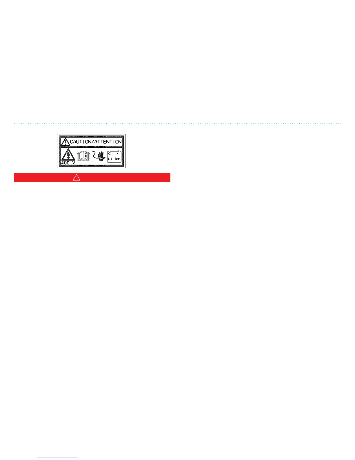
The THINK CITY has high voltage systems that can cause
electrical shock possibly resulting in serious injury or death.
Your vehicle was built with safety as a fundamental concern,
but reasonable care must be exercised including:
• Do not tamper with orange high voltage wiring or any
component attached to such wires, or in the event of an
accident, do not touch orange high voltage wiring or any
component attached to such wires.
• Pay attention to the warnings in this manual and to all
labels in the vehicle.
• Do not work on the electrical system of the vehicle and
allow only qualified personnel to do such work.
• Only use the charging cable supplied with the vehicle
and do not use that cable if it is damaged in any way.
!
WARNING
!
CAUTION
Page 5
Introduction
II
Congratulations on acquiring a THINK City!
We at THINK NA are pleased with your choice of the THINK
City EV, a zero-emission vehicle (ZEV) that will benet the
environment and your driving pleasure. In our opinion, THINK
City is the best choice of vehicle with regard to reduction in
emissions, and we have invested a considerable amount of
eort and resources to make THINK City a practical, safe and
economical vehicle.
This User Manual
In this manual you will nd relevant information and answers
to typical questions. As you will notice, we provide important
illustrations and use a simple structure for easy reference.
If you are unable to nd information on specic topics, or if
you feel a better explanation is needed on something, please
contact your local THINK NA dealer.
Other Documentation
In addition to this User Manual, you will nd the following in the
documentation packet:
• Battery Manual
• Service and Warranty Manual
• Portable Charger System Manual
• Radio Owner’s Manual (if equipped)
• Original Equipment Passenger and Light Truck Tire Owner’s
Manual and Limited Warranty
Please read the documents carefully to understand this
vehicle’s unique functionality and what you can expect from it.
Warranties and Repair
If you experience equipment failure, contact your dealer or
other authorized THINK NA workshop. Be sure to become
familiar with and follow the recommendations in the Service
and Warranty Manual for THINK City.
To ensure safety, the vehicle must only be charged from a
grounded power supply. No other connection must be used.
!
WARNING
Page 6
Introduction
III
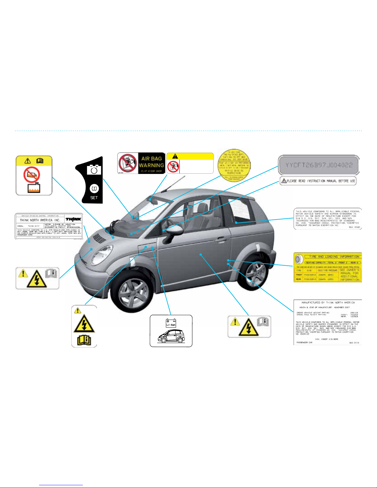
Symbols/Labels
Coolant,
replenishment
Battery reset
(not applicable),
TPMS set
Air bags and children/
child safety seats
Disconnecting
air bag
Vehicle
identification
High voltage
warning
Battery identification
High voltage
warning
High voltage
warning
U.S. certification
Tire and loading
Exemption
Emission
WARNING
DEATH or SERIOUS INJURY can occur
Children 1 2 and un der can be kil led by the air bag
The BACK S EAT is the safest place for chi ldren
NEVER put a rear-fa cing ch ild sea t in fro nt unle ss
air bag is off
Sit as far back a s possi ble from the ai r bag
ALWAYS use SEAT BELTS and CHILD R ESTRAIN TS
575. 0040
Page 7

This chapter is a quick reference guide to all the main features in
your THINK City.
It is important to notice important issues connected to driving an
electric vehicle.
You will nd more of the descriptions in this chapter and
elsewhere in this User Manual. If anything is unclear, please
contact your dealer.
Read the User Manual carefully to achieve maximum utilization of
the vehicle.
1. Get to Know Your THINK City
Page 8

1. Get to Know Your THINK City
12
Page 9

1. Get to Know Your THINK City
13
Table of Contents
Important Information ............................................................................................................................................... 14
California Proposition 65 ..........................................................................................................................................15
Exterior ..............................................................................................................................................................................16
Interior ...............................................................................................................................................................................18
Instrument Cluster .....................................................................................................................................................110
Charging ...........................................................................................................................................................................111
Traction System ........................................................................................................................................................... 113
How to Start/Stop the Vehicle ................................................................................................................................114
Open/Close/Lock System......................................................................................................................................... 115
Motor Compartment ..................................................................................................................................................116
Luggage Area ................................................................................................................................................................. 117
Technical Data/Recycling .......................................................................................................................................118
Page 10

1. Get to Know Your THINK City
14
Important Information
THINK City is a safe vehicle
THINK City is a certied vehicle under the National Motor
Vehicle Safety Act. THINK City has been developed in
cooperation with leading automobile industries involved in
vehicle safety, and has been tested by highly regarded test
laboratories throughout the world.
Simple service and maintenance
Your THINK City is easy to maintain with fewer parts in need of
service.
The outer body panels are made of dyed-throughout plastic, to
avoid dents, paint damage or corrosion.
The battery is maintenance-free, with a long lifetime.
THINK City is a simple vehicle to use
• THINK City can be driven like all other vehicles.
• The ignition key turns the vehicle on and o.
• The electric motor is controlled by the accelerator pedal.
• The gear box functions as an ordinary automatic
transmission.
• The energy level is shown on the instrument cluster.
• The vehicle battery can be charged with a standard,
grounded outlet box (120V or 240V and 10 A or 15 A).
Federal and local authorities are encouraging people to switch
to zero-emission vehicles (ZEV) by oering dierent incentives,
such as:
• Cash incentives from federal and local governments
• No toll charges on roads
• Free parking and free charging
• Tax credit benets
• Use of public transport lanes
• Use of carpool lanes
Contact your local authorities to nd out which incentives they
are oering for electric vehicles.
!
WARNING
THINK City is an electric traction vehicle with a molded plastic
vehicle body. This makes THINK City different from other
vehicles in many ways.
The most important are:
• THINK City is virtually silent. Remember that other
drivers and pedestrians might not be able to hear
you coming. Use extreme caution in crossroads and
pedestrian areas.
• Cleaning and maintenance of the plastic vehicle body is
different from a standard painted vehicle. See Chapter 5,
Service and Maintenance, in this manual.
• Charging the traction battery is a simple procedure. Read
and learn about this and the charger cable in this chapter
and also in the Portable Charger System Manual.
Important Information
Page 11

1. Get to Know Your THINK City
15
California Proposition 65
!
WARNING
• Certain vehicle components may contain or emit chemicals
known to the State of California to cause cancer and birth
defects or other reproductive harm. In addition, certain
fluids contained in vehicles and certain products of
component wear may contain or emit chemicals known to
the State of California to cause cancer and birth defects or
other reproductive harm.
• Certain components of this vehicle, such as air bag modules
and seat belt pretensioners, may contain Perchlorate
Material. Special handling may be required for service
or vehicle end of life disposal. See www.dtsc.ca.gov/
hazardouswaste/.
California Proposition 65
Page 12
1. Get to Know Your THINK City
16
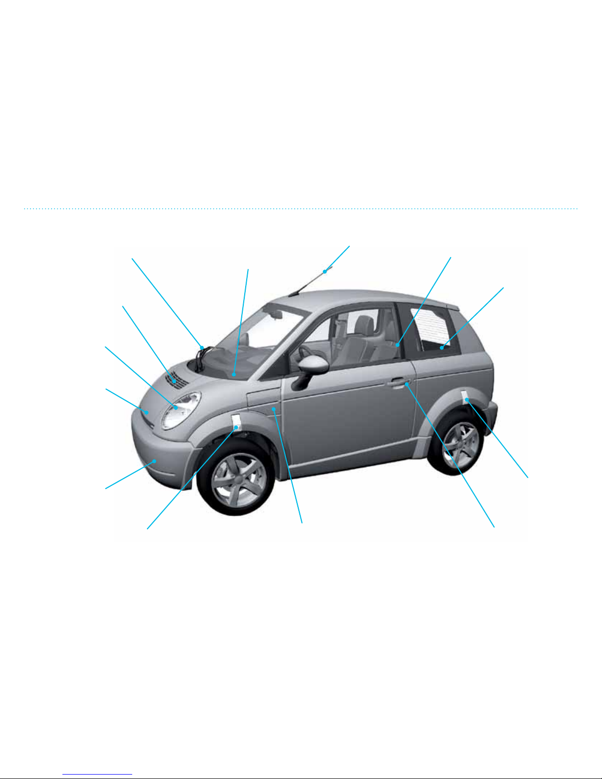
Exterior
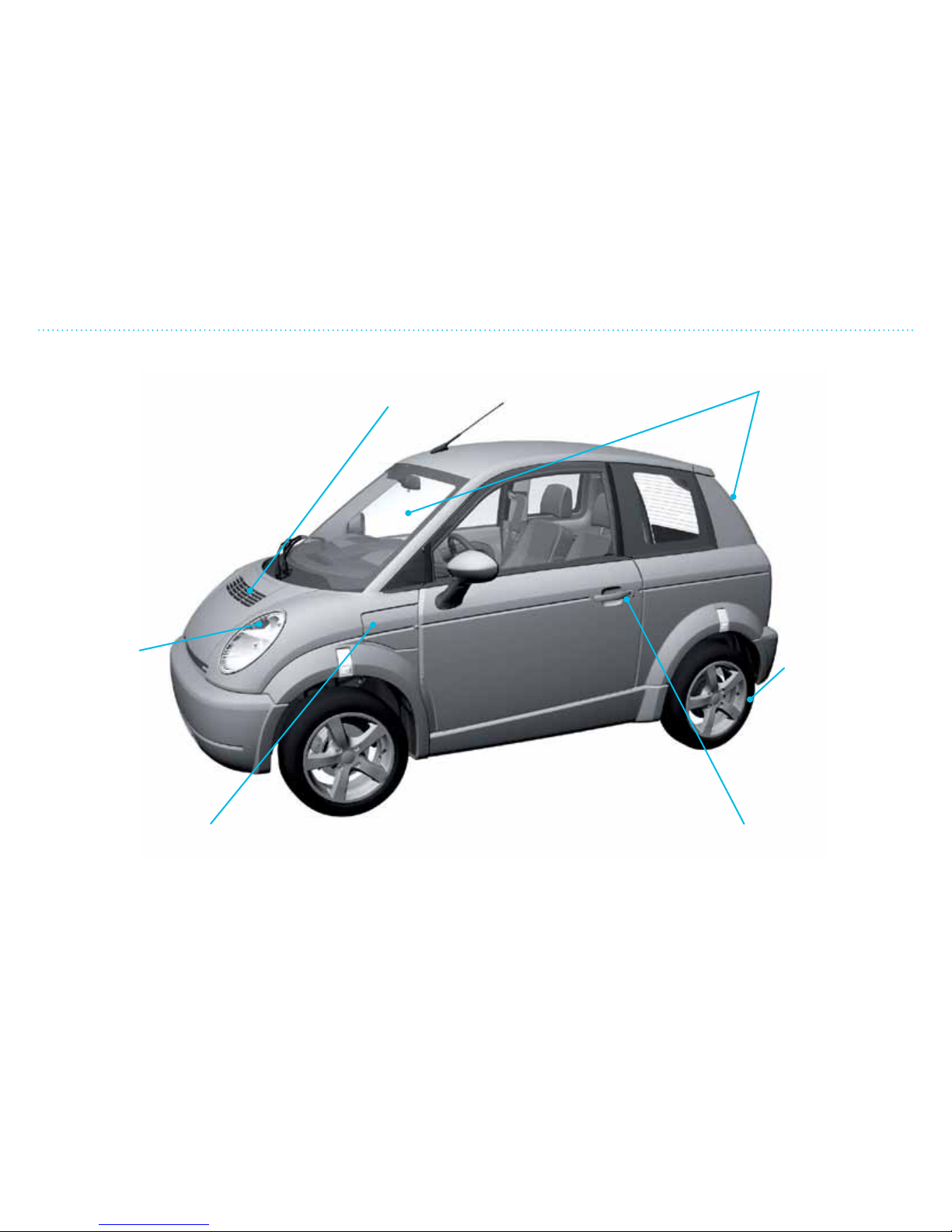
One wiper covers
the whole windshield
Vehicle
identification
number
Antenna for radio
Seats with
safety belts
Luggage
compartment
Reflector
Door handle/lock.
Remote control of
lock is standard.
Charger hatch
Connection point for charging cable and
identification of battery type.
Combined main
light/park light/
turn signal
Hood, can be
released from
driver seat
Energy-absorbing
safety bumper
Turn signal
Air intake for air
conditioning system
Exterior
Page 13
1. Get to Know Your THINK City
17
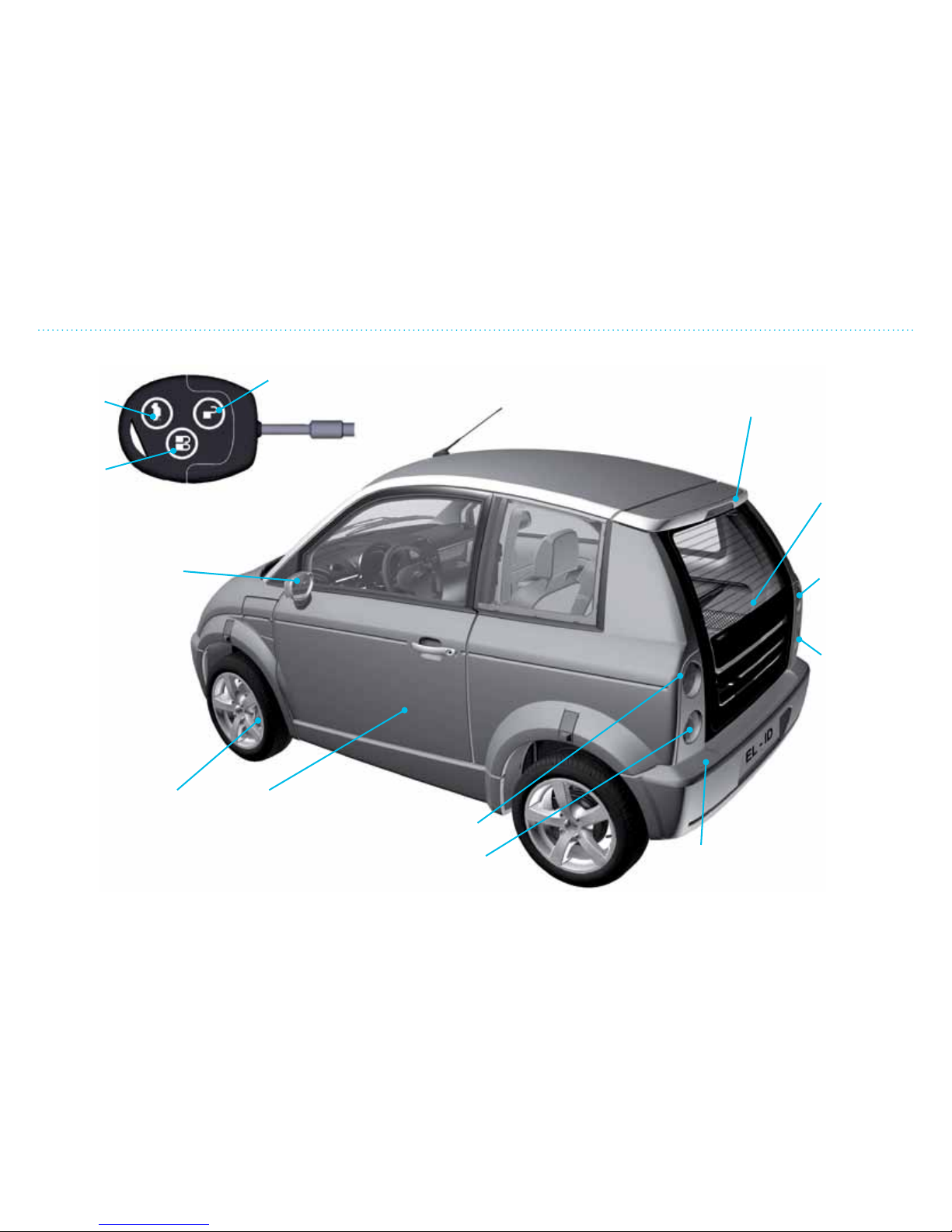
Exterior
Opens
rear
hatch
Locks
side
doors
Electric mirror,
adjusted with button
between seats
Tire and rim (for
recommended tire
pressure, see page
5-20)
Turn signal/
reverse lamp
Brake light/
tail light
Vehicle outer
body made of
dyed-throughout
plastic
Energy-
absorbing safety
bumper
Brake light/
tail light
Turn signal/
reverse lamp
Rear hatch,
opened from
inside or with
key fob
High-mounted
brake light
Unlocks
side doors
Functions on the key fob:
Page 14
1. Get to Know Your THINK City
18
Interior
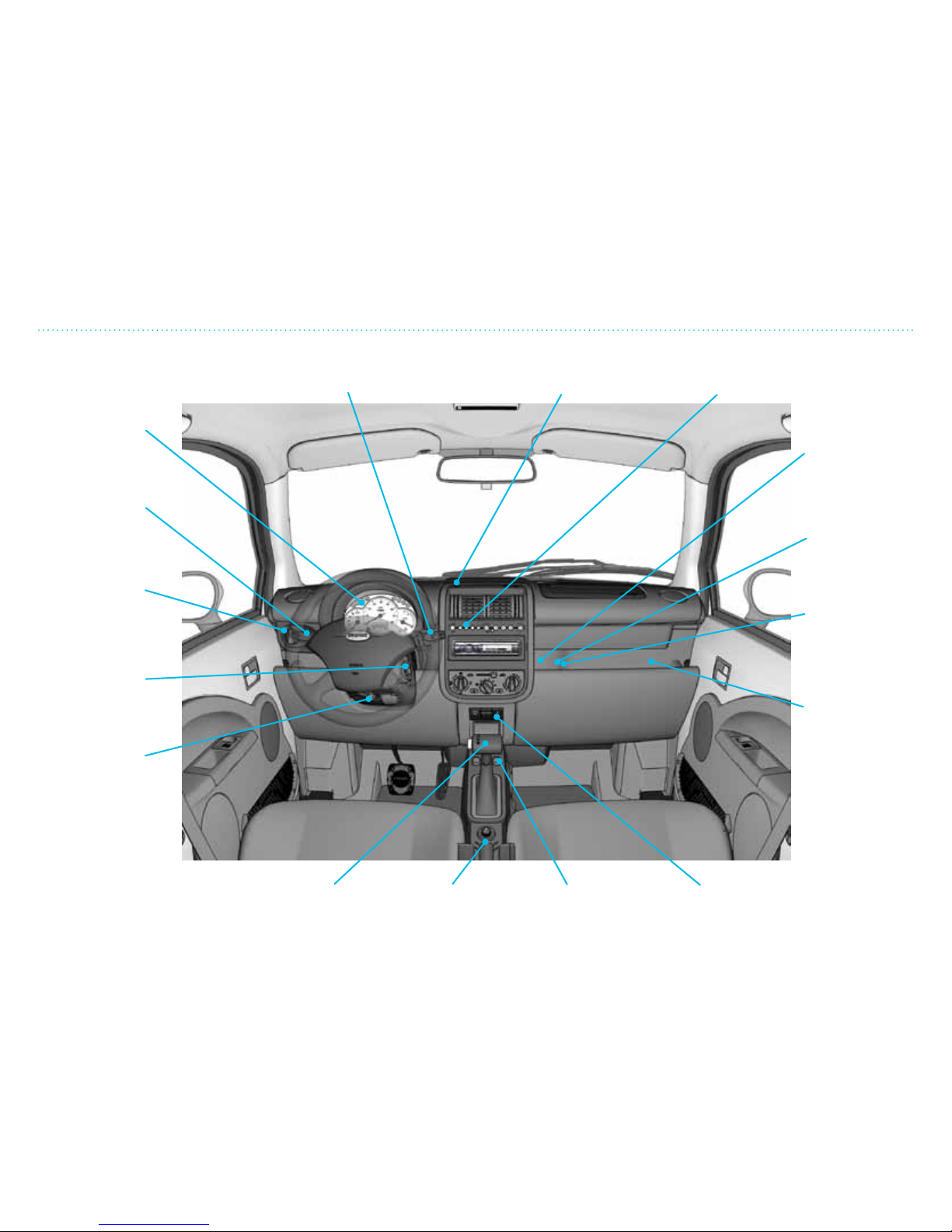
Windshield wiper/
windshield washer
Row of indicators/
warning lamps
Indicator, start-up
locking system
Emergency
hazard switch
Window
adjustment
Parking brakeGear selector
Steering wheel
adjustment
Ignition lock
on/off switch
Open rear
hatch
Instrument
cluster/warning
lamps
Turn signal/
high beam/
head lamp
flasher
Disconnect air
bag, passenger
seat
TPMS set
button
Connection
for diagnosis
(for service
personnel)
Fuse box 12V
Interior
Page 15
1. Get to Know Your THINK City
19
Interior
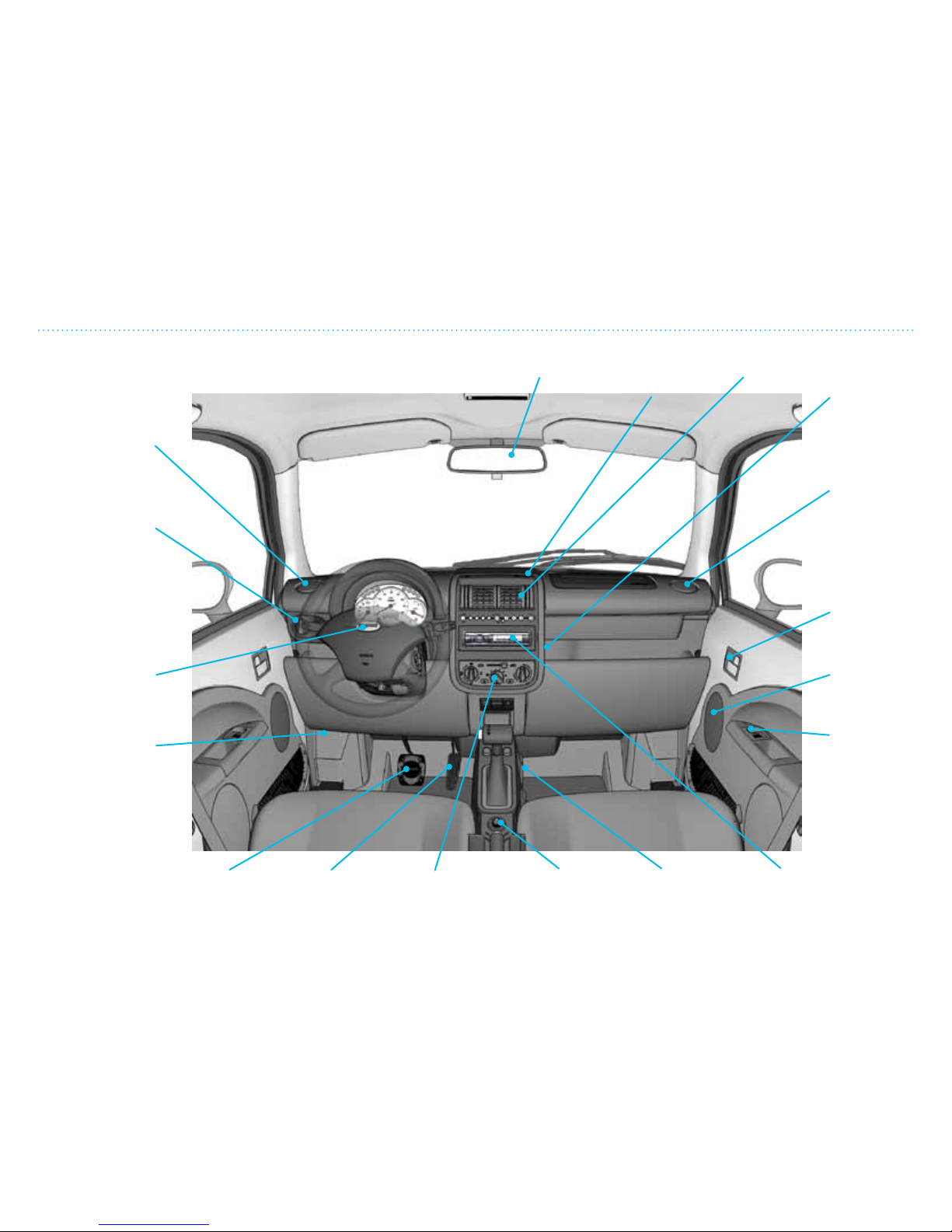
Rear view
mirror
Ventilation
Light switch/
instrument lights
Horn
Hood release
knob
Battery
charging
indicator
Cabin air
vents
12V outlet
Ventilation
Door
opener/
door lock
Speaker
Coin box
Radio/CD player
(if equipped)
Cup holdersExterior
side mirror
adjustment
Heat/AC
ventilation
Accelerator
pedal
Brake pedal
Page 16
1. Get to Know Your THINK City
110
mph
10
0
100
80
60
40
20
0
20
30
40
50
60
70
80
0
90
100
110
120
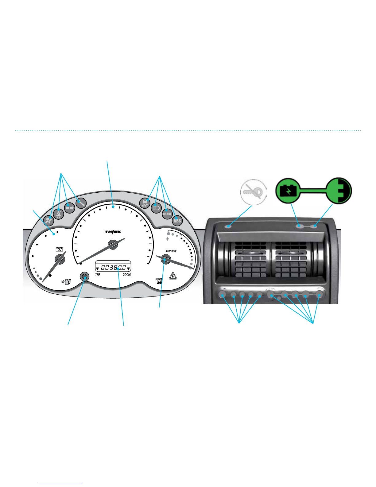
Instrument Cluster
Control and
warning lamps
Energy level
gauge
Control and
warning lamps
Illuminated
when charging
is in progress
Illuminated when
the external
power supply is
connected
Gear indicator
lamps
(see Chapter 2,
page 2-9)
Indicator/Warning
lamps
(see Chapter 2,
page 2-9)
Economy
gauge
Odometer
Odometer trip
button
Lock indicator.
Flashes when the key is
removed from the lock.
The indicator is off when
the vehicle is
running.
In case the
lamp illuminates
continuously, or
flashes rapidly,
contact dealer.
Speedometer
Instrument Cluster
Page 17
1. Get to Know Your THINK City
111
Charging
Charging
Charging the traction battery is a straight-forward and safe
process. THINK City is supplied with a portable charger system
(PCS) that includes a control unit with cables for connections
to the electrical outlet and the vehicle. To charge the battery,
connect the charging cable supplied with the vehicle to the
electrical outlet.
The connection is made through the hatch on the driver side of
the vehicle, in front of the driver side door.
You will also nd more information on proper charging
procedures and troubleshooting in the Portable Charger System
Manual provided along with this manual.
To charge the battery:
!
WARNING
• Always follow the charging directions carefully. If you don’t,
you may cause damage to the vehicle and/or the connected
electrical outlet, injury to persons or accidental death.
• Inspection of the charge cable is required before use. A
defective charge cable may cause an electric shock, with
possible injury or accidental death, and/or damage to
vehicle or building due to overheating.
!
CAUTION
It is not possible to charge the traction battery if the 12V battery
is completely discharged.
1. Park the vehicle with the gear selector in P (Park) and engage
the parking brake.
2. Place the charging cable so that the PCS does not exert undue
pressure on the cable and/or electrical outlet.
3. Always check the charging cable for any damaged areas.
4. Connect charging cable to
power supply. Maximum safety
is achieved when the charging
cable is rst connected to the
electrical outlet and then to the
vehicle.
5. Open the charger plug lid with
your thumb, liing upwards and connect charger plug to
vehicle socket.
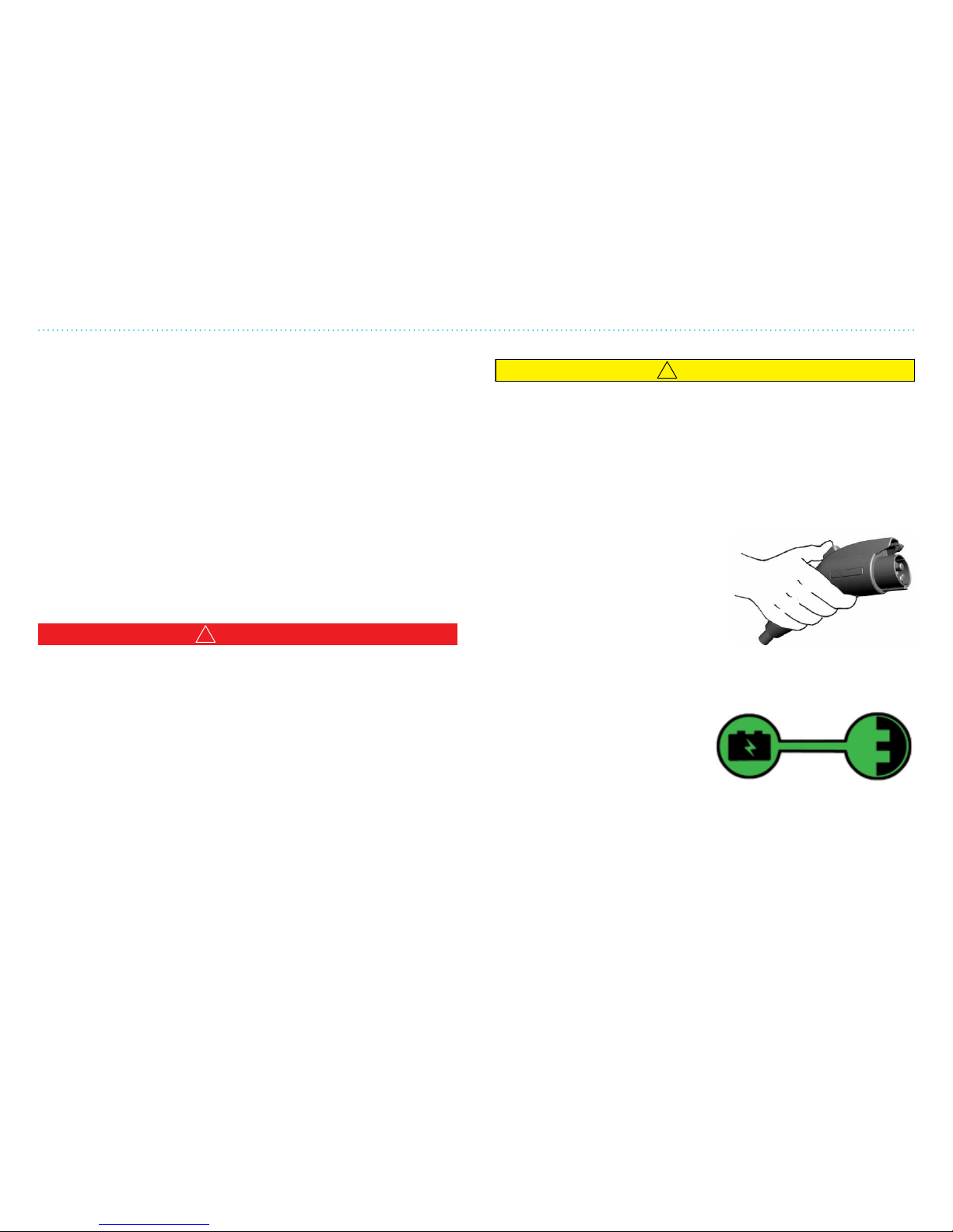
6. Ensure that the battery
charging indicator lamp in the
vehicle illuminates and the
economy gauge needle in the
instrument cluster is in the +
region.
7. The charge time is dependent upon the total capacity of
the battery, how much ampere-hour capacity is le and the
amount of current used.
Page 18

1. Get to Know Your THINK City
112
Refer to the Portable Charger System Manual and the Battery
Manual for more information on proper charging procedures
and estimated charging hours for your vehicle.
Delayed Charge Startup
!
CAUTION
If the battery charging indicator lamp in the vehicle flashes on
the battery portion, it indicates that the charging is on hold for
the batteries to reach appropriate temperature. This is normal.
Once the appropriate temperature is reached, charging will
start and the lamp will continuously illuminate.
The vehicle safety systems will monitor the battery and the
battery’s temperature. If the battery is outside chargeable
temperature range, for instance immediately aer driving, if the
battery temperature is too high, the charging will be delayed
until the battery temperature has decreased suciently. This
condition will be indicated by slow ashing of the battery
charge indicator.
Estimated Charging Hours
Charging time is dependent upon how much ampere-hour
capacity is le, and the total capacity of the battery. For more
information on battery types, capacity and charging time, see
Battery Manual provided with this documentation packet.
Removing the Battery Charging Cable
1. Detach the battery charging cable from the vehicle.
2. Close the charger hatch.
3. Detach the battery charging cable from the electrical
outlet.
4. Put the battery charging cable in its usual place, under
the rear storage compartment. THINK NA recommends
keeping the battery charging cable in the vehicle.
NOTE: It is recommended that the battery charging cable is
disconnected from the vehicle rst and then from the electrical
outlet.
Charging and Charge Cable
Page 19
1. Get to Know Your THINK City
113
Traction System
Traction System
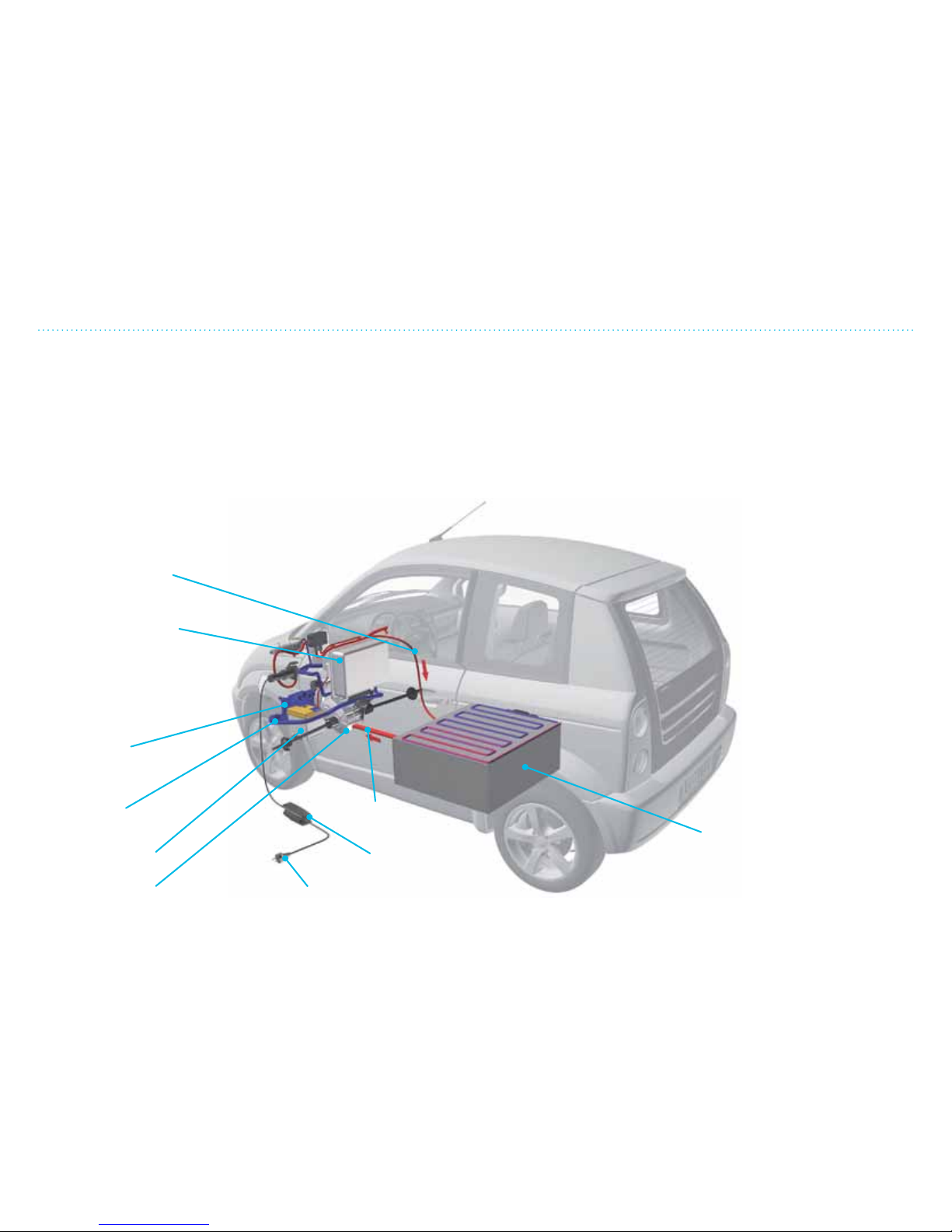
THINK City is a front-wheel drive vehicle and is driven by an
electric motor through a xed reduction gear. The electric
motor supplies ample torque over the entire rpm range. The
motor gets its power (electricity) from the traction battery
(see Battery Manual).
The THINK G4 EV drive controller monitors the electrical
charge and utilizes the energy eciently. It also regulates the
motor to act as a generator when the accelerator is released.
The traction battery is charged by connection to 240V
(recommended) or 120V from a normal grounded electrical
outlet. A built-in battery charger converts AC in the power grid
to DC to charge the battery in the most optimal way. Charging
stops automatically when the battery is fully charged. The
on-board vehicle charger, drive controller and motor are liquid
cooled. Two pumps circulate coolant to the individual units to
maintain the correct temperature.
Charging current
to the battery
Coolant
system
THINK G4 EV
drive controller
Radiator
12V battery
Motor and
gears
240V/60 Hz
Traction battery
Control unit
Power to
the motor
THINK City also has a
separate 12V system
which powers the
headlights, windshield
wiper, instruments,
ventilation fan, etc. The
12V battery is charged
by the traction battery
via a converter built
into the drive controller.
Page 20

1. Get to Know Your THINK City
114
How to Start/Stop the Vehicle
How to Start the Vehicle
1. Disconnect the battery charging cable.
2. Make sure the gear selector is in P (PARK).
3. Turn the ignition key to position
II, and then to position III and then
release. There will be a humming
sound and all gear indicator lamps
(green) will illuminate.
4. When the motor starts, the telltale
lamp showing a green vehicle will
illuminate. Make sure all warning and caution
lamps are o.
5. Press the brake pedal and move the gear
selector to desired position.
6. Release the parking brake and press the accelerator pedal.
You can also start the vehicle if the gear selector is in N
(NEUTRAL).
NOTE: The vehicle is equipped with a park-brake interlock. You
must press the brake to shi the gear selector out of P (Park).
How to Stop and Turn Off the Vehicle
1. Press the brake pedal until the vehicle has come to a
complete stop.
2. Ensure that the vehicle is not moving.
3. Move the gear selector to P (PARK) and engage the
parking brake.
4. Turn o the ignition (move to position 0).
5. Remove the ignition key and lock the vehicle.
How to Open the Rear Hatch
From inside the vehicle: Push the button for opening the rear
hatch.
Using key fob: Push the symbol for opening the
rear hatch twice quickly (works only with ignition
key in 0, or ignition key removed).
!
CAUTION
Make sure the rear hatch is latched before driving (it can
appear closed without actually being latched).
Access Light
Open doors with the key fob to switch on the interior light. The
light will switch o aer 25 seconds if all doors are closed.
The light will switch o if the vehicle is started or locked with
the key fob.
See Chapter 2 for more information.
I
II
III
0
Page 21
1. Get to Know Your THINK City
115
Open/Close/Lock System
Keys and Lock Systems
!
CAUTION
Keep the keys in a safe place and out of reach of children.
Children could accidentally open the vehicle and injure
themselves or others or cause damage to the vehicle.
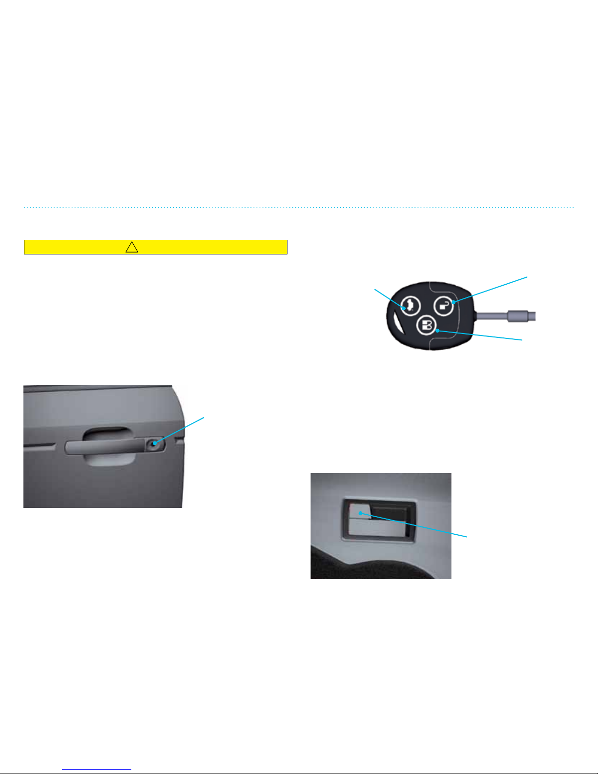
THINK City is equipped with two remote control key fobs. The
vehicle can be opened manually with the keys (only on driver
side) if the remote control does not work.
THINK City is equipped with an advanced starter lock system.
The vehicle can only be started with these coded keys (see
Chapter 2).
Manual open/lock
with key (only
on driver side).
Activate central
locking device.
Key Fob
Both key fobs are equipped with a remote control to lock or
unlock the vehicle. Push the desired function on the key fob.
NOTE: If the open button on the key is pressed and none of
the doors are opened or the ignition is not activated within 45
seconds, the central locking device will automatically lock the
doors.
Change Key Fob Battery
See “Service and Maintenance”, page 519.
Central Locking Device
THINK City is equipped with a central locking device to lock all
the doors with the interior
door lock on the driver side
or on the key fob.
Opens rear
hatch
(push twice)
Unlocks
side doors
Interior door lock
(activates central
locking device)
Locks side
doors
Page 22
1. Get to Know Your THINK City
116
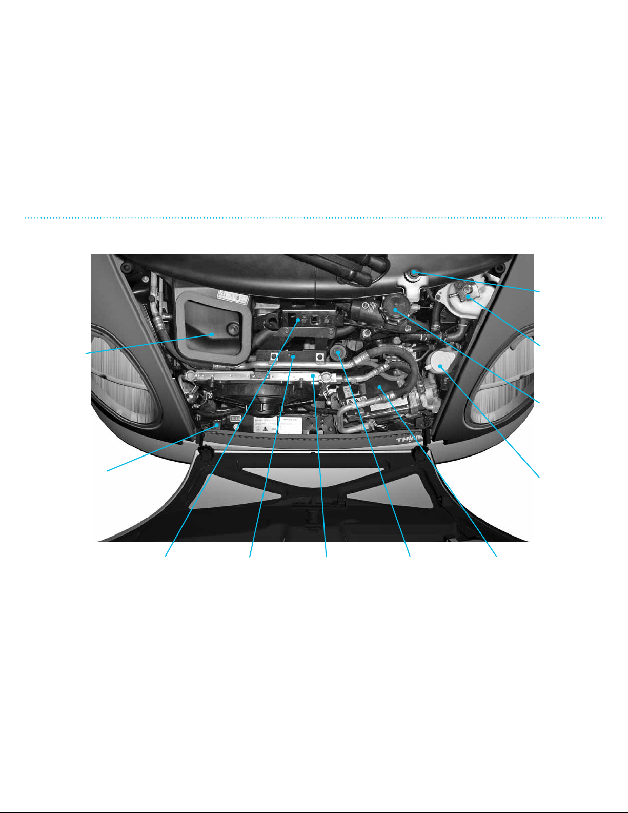
Motor Compartment
Air intake for
ventilation
Inertia sensor
for battery
disconnect
THINK G4
EV drive
controller
Motor and
gear
Refill for
power
steering fluid
Radiator 12V battery
Refill
windshield
washer fluid
Vacuum
pump for
power brake
Refill coolant
Refill brake
fluid
Motor Compartment
Page 23
1. Get to Know Your THINK City
117
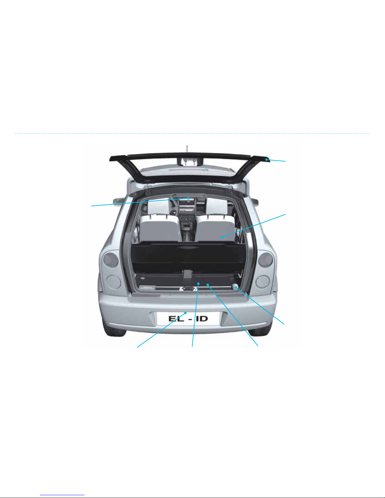
Luggage Area
Interior
compartment
light (roof lamp)
License plate
light
Storage area Roadside
warning
triangle
Tire repair kit
Storage net on
back side of
seats
Rear hatch
Luggage Area
Page 24

1. Get to Know Your THINK City
118
Technical Data/Recycling
Temperature Limits
THINK City works under the following temperatures:
Green = normal performance
Yellow = reduced performance
Red = storage only
Fully Recyclable
THINK City was designed to create minimal impact on the
environment in all phases of its usable lifetime. The unique way
the vehicle is built makes it easy to disassemble for recycling.
The dyed-throughout plastic body emits no poisonous gasses
during production and can be melted down and re-used.
The dye comes from natural pigments which eliminates the
need for painting and the fumes resulting from that process.
The framework is of aluminum and steel which can easily be
recycled.
Technical Data/Recycling
Down to
-40°F
Down to
-13°F
-4°F
+104°F
Up to
+122°F
Up to
+185°F
Page 25

The rst thing you will see when you get into your THINK
City is the instrument cluster, which is arranged to give you
a clear overview of the controls. Here you will nd control
and warning lights as well as instruments that inform you of
the status of certain vehicle functions before you start the
vehicle and when the vehicle is driven.
2. Overview of Instruments and Controls
Page 26

2. Overview of Instruments and Controls
22
Page 27

2. Overview of Instruments and Controls
23
Table of Contents
Overview Instruments .............................................................................................................................................. 24
Main Instrument Cluster with Warning Lamps ..............................................................................................26
Interior and Climate Controls .................................................................................................................................28
Gear Selector and Indicator ..................................................................................................................................... 29
Main Light Switch, Turn Signal and Instrument Panel Lights ...............................................................210
Ignition Lock and Emergency Hazard Switch ................................................................................................211
Windshield Wiper, Defroster and Horn ........................................................................................................... 212
Start-up Locking System, Steering Wheel and Parking Brake ............................................................... 213
Page 28
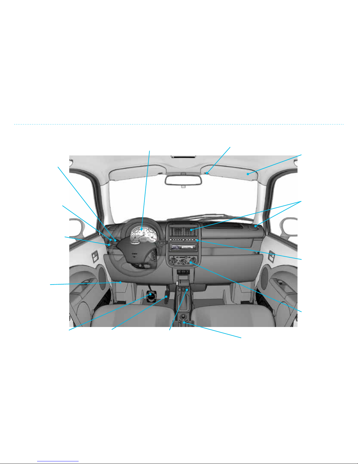
2. Overview of Instruments and Controls
24
Overview Instruments
Lever to open
rear hatch
Main instrument cluster
(see page 2-6 and 2-7)
Main head lamps
switch (see
page 2-10)
Lever to open
the hood
Brake pedal
Electric window
switches
(up/down)
Parking brake
(see 4-14)
Heating, A/C and
ventilation
control knobs
(see Chapter 3)
Gear indicator
(see page
2-9)
Ventilation
vents
Sun visor release
Sun visor
with mirror
Accelerator
pedal
Turn signal/
high beam
head lamps/
head lamp
flasher (see
page 2-10)
Overview Instruments
Page 29
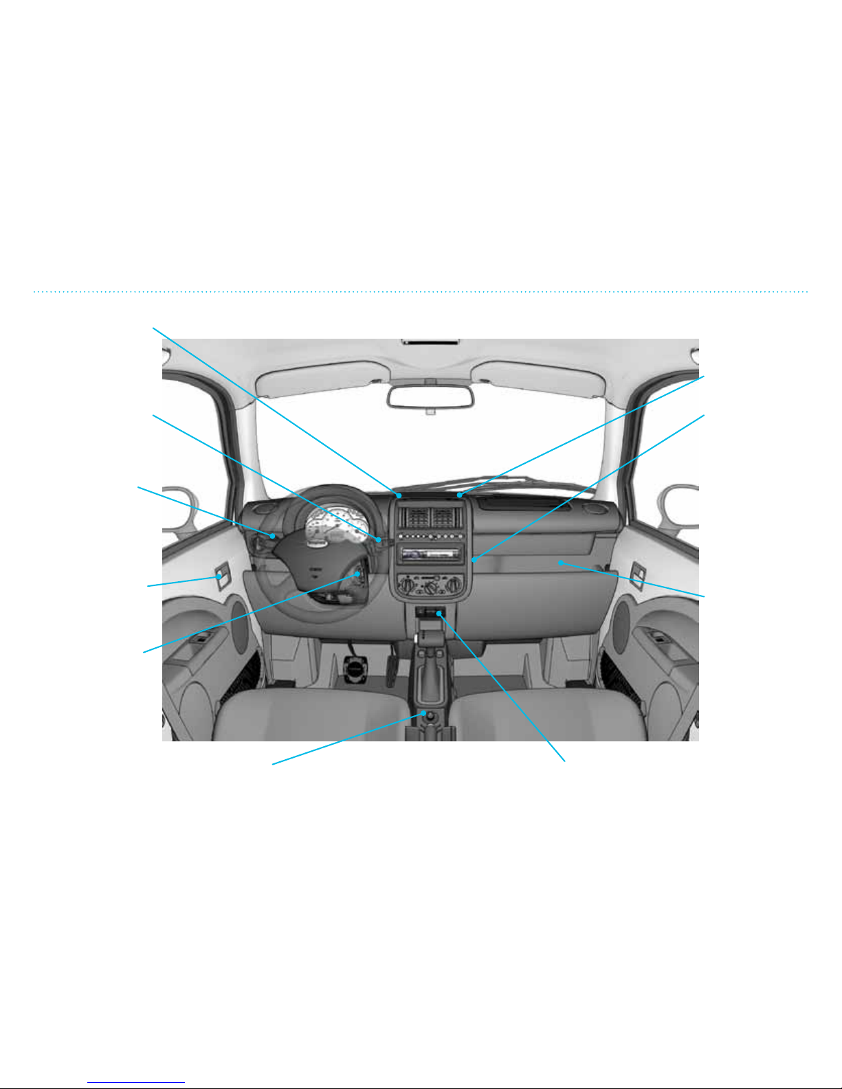
2. Overview of Instruments and Controls
25
Overview Instruments
Indicator for start
and ignition locking
system
Windshield
wiper/washer
(see page 2-12)
Instrument panel
light (see page
2-10)
Door opener/
door lock
Ignition lock
Indicator for
charging
Storage
compartment
12V outlet
plug for 12V
equipment. Max
load is 200 W.
Always keep
cover on when
not in use.
Exterior side mirror adjustment
(see page 2-8)
Emergency hazard switch. Activates hazard
lights. Works also when ignition is off. Press once to
activate and again to turn off.
Page 30
mph
10
0
100
80
60
40
20
0
20
30
40
50
60
70
80
0
90
100
110
120
2. Overview of Instruments and Controls
26
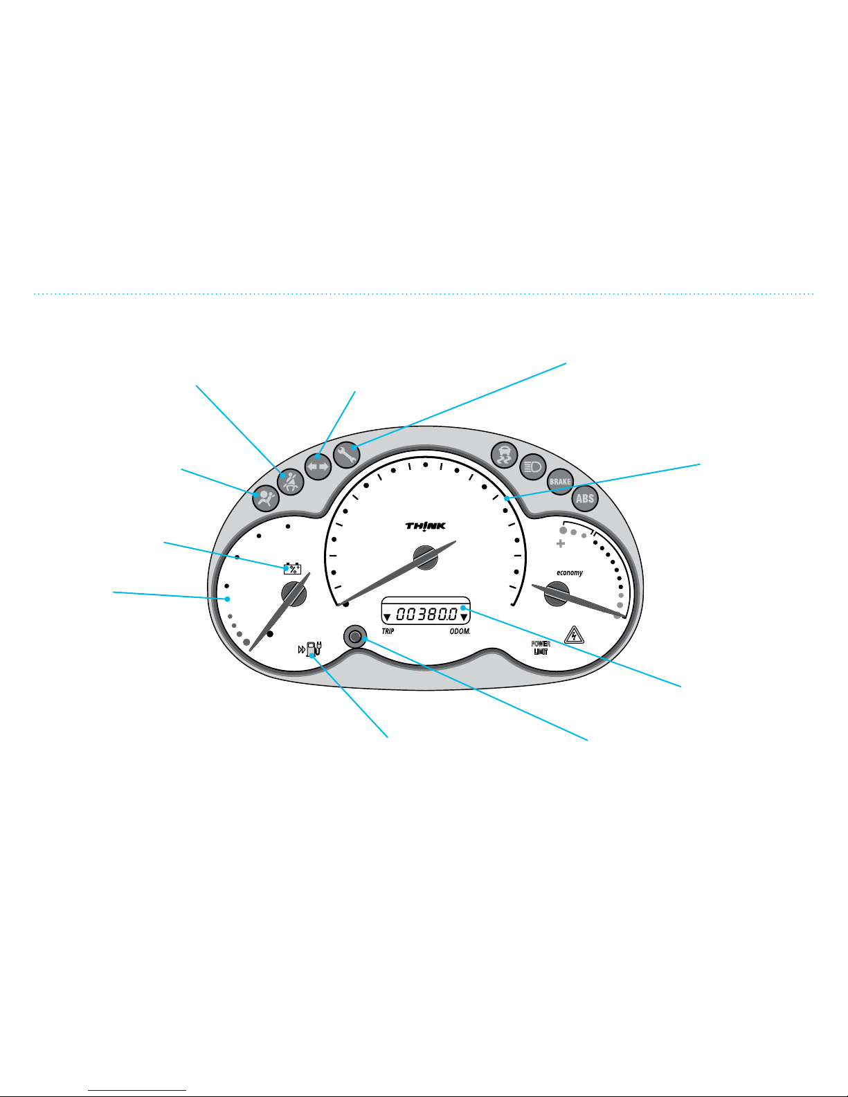
Main Instrument Cluster with Warning Lamps
Warning lamp for safety
belts. Illuminates when the
driver or passenger has not
fastened the safety belt.
Warning lamp
for turn signal and
emergency hazard switch.
Speedometer.
Shows the
vehicle’s speed.
Warning lamp for faulty equipment.
Illuminates if there are faults in the
electrical system. If constantly on,
contact your dealer.
Warning lamp for air
bags. Illuminates or
blinks continuously if
there is a fault in the air
bag system.
Charge level.
Shows the traction
battery’s charge level.
100% means the battery is
fully charged. If under 5%, the
power output will be noticeably
reduced (to economize range
with the remaining charge available).
0% means the battery is completely
discharged and must be charged to
avoid damage. The charge gauge
is active during both charging and
driving. When the ignition is off, the
gauge will show the charge level
when the vehicle was last driven.
Warning lamp
indicating low power
of 12V battery.
Warning lamp for
low battery charge.
Illuminates continuously if
the charge is under 10%.
Blinks rapidly when the
charge is 0%.
Trip odometer
button. Hold in for
2 seconds to reset.
Push quickly to
select the function.
The odometer
registers the vehicle’s
total driving distance.
The trip counter
shows the number
of miles/kilometers
driven from that
starting point.
Main Instrument Cluster with Warning Lamps
Page 31
mph
10
0
100
80
60
40
20
0
20
30
40
50
60
70
80
0
90
100
110
120
2. Overview of Instruments and Controls
27
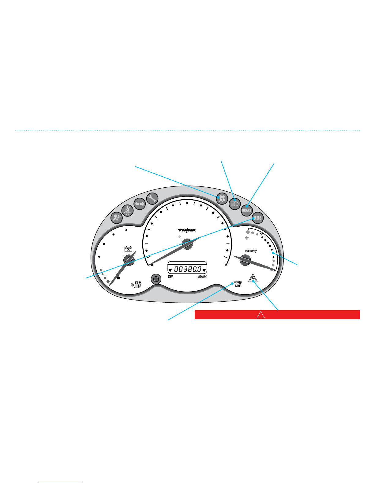
Main Instrument Cluster with Warning Lamps
Warning lamp for electronic stability program
(ESP) (if equipped). Illuminates briefly when
you switch on the vehicle and then goes out.
Warning lamp flashes whenever an ESP event
occurs. If it illuminates continuously while
driving, the ESP system is not fully operational
and the vehicle should be checked by the
dealer as soon as possible.
Warning lamp for faults in the
brakes. If lamp illuminates
continuously, it indicates a
severe brake system fault. If
this happens, stop the vehicle
in a safe manner and get it
checked by the dealer as soon
as possible.
NOTE: This lamp will also illuminate
if the hand brake is engaged.
Before driving the vehicle,
always ensure that the hand
brake is disengaged.
Warning lamp for high
beams. Illuminated when
high beams are on.
Warning lamp for limited
output. Illuminated when
the motor’s power is limited.
Warning lamp for anti lock
brake system (ABS).
Illuminates for a few
seconds when the vehicle
is started. If the lamp
does not illuminate when
the vehicle is started or
if the lamp is illuminated
continuously, the ABS will
not work and the vehicle
should be taken to the
dealer as soon as possible.
Economy gauge.
Shows the vehicle’s
power consumption.
While driving the
vehicle, if the indicator
is in the green field, the
vehicle is charging the
battery (regenerative
braking). See page 4-12
for more information.
!
WARNING
If illuminated, the telltale lamp indicates a fault in the
high voltage system. Charging is not possible if the light is
continuously illuminated. Contact your dealer if the lamp
does not illuminate a few seconds at start-up or remains
illuminated while driving.
Page 32
2. Overview of Instruments and Controls
28
Interior and Climate Controls
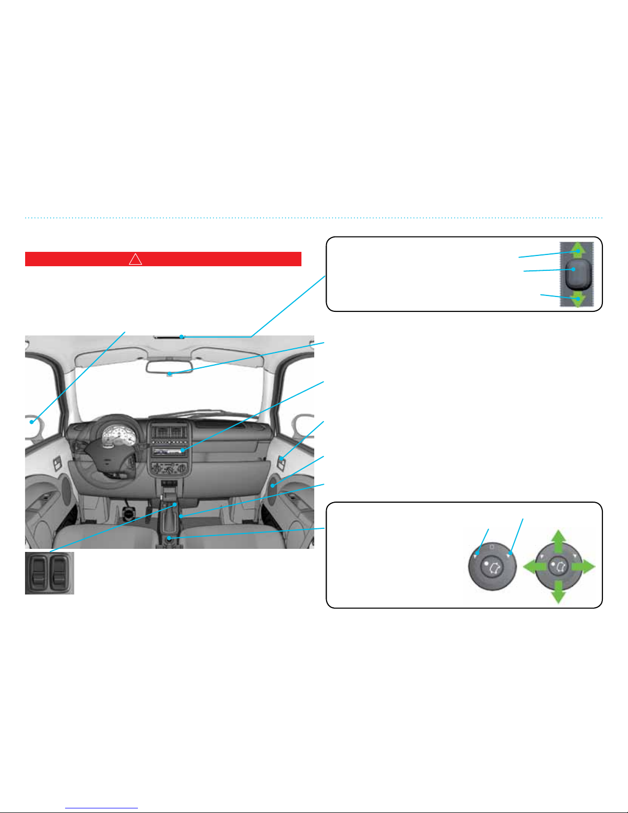
The interior dome lamp illuminates when:
• The doors are closed and the switch is on.
• The door activation switch is on and one or
more doors are open.
When the door activation switch is off, the dome
lamp will not turn on if a door is opened.
Side exterior mirror. Electric adjustment only,
cannot be moved manually
Button for adjusting side
exterior mirrors
Driver side
mirror
Choose which mirror to adjust
by rotating the switch left/
right. Move the switch up/
down or right/left to adjust
mirror to the correct position.
Once adjusted, return the
switch to the middle position.
Passenger
side mirror
Electric window opener. Can only be
operated when the vehicle is running.
!
WARNING
When children are in the vehicle: Be sure that their heads and
fingers are clear of the windows before closing. Never leave the
vehicle with the key in the ignition.
Cup holder
Speaker for
radio/CD player
Door opener/
door lock
Radio/CD player (if equipped)
see radio owner’s manual
Rear view mirror (interior) with night
adjustment (push handle back)
Interior and Climate Controls
Page 33
2. Overview of Instruments and Controls
29
Gear Selector and Indicator
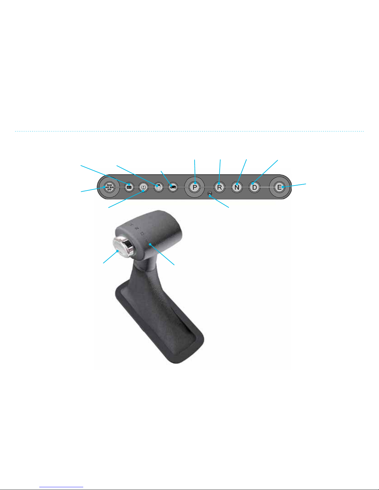
Brake-shi Interlock Feature
There is a gear lock which stops the
gear selector from moving into or out
of P (PARK), unless the brake pedal is
engaged. The vehicle will not move when
it is put in P (PARK).
This parking lock function will disengage
automatically when the gear selector is moved
out of P (PARK).
Warning lamp that
indicates insufficient
charge in the 12V
battery
Warning lamp
for open doors
Telltale lamp
to indicate the
vehicle is ON
Warning lamp for tire pressure
monitoring system (TPMS)
Gear lock
release
button
Gear
selector
EFFICIENCY DRIVING
Indicator shows that the gear selector is
locked until the brake pedal is pressed down.
DRIVENEUTRALREVERSEPARK
Warning lamp for
disconnected air bags
on passenger side
Gear Selector Positions
• Hold the brake pedal down and press on the gear lock
release button before moving the gear selector from P
(PARK) to another gear.
• P (PARK) – The vehicle must be stationary before it is put
into P. The vehicle must be in P to remove the ignition key.
If the doors are open and the gear selector is not in P,
there is a repeated warning beep. Gear selector cannot be
shied to/from P unless the ignition key is in position.
• R (REVERSE) – When the gear selector is in R, the vehicle
will move backward when the brakes are released.
• N (NEUTRAL) – When the gear selector is in N, the vehicle
can be started and will move freely. Apply the brakes to
stop the vehicle.
• D (DRIVE) – With the gear selector in D, the vehicle will
move forward.
• E (EFFICIENCY DRIVING) – Limits power output and
increases regenerating level to allow for more energyecient driving.
Gear Selector and Indicator
Page 34
2. Overview of Instruments and Controls
210
Main Light Switch, Turn Signal and Instrument Panel Lights
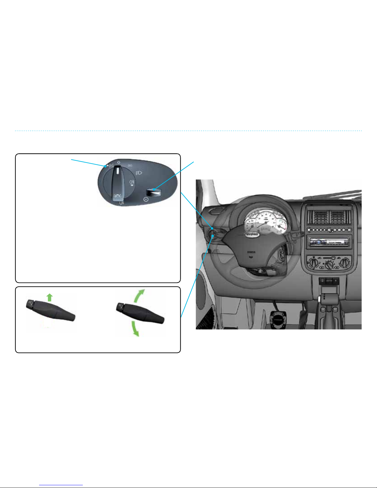
Instrument Panel Lights
The brightness of the lights are adjusted by turning the
adjusting wheel le or right. The instrument panel lights work
only when the main or parking lights are on.
Main Light Switch
One click to the left turns on
front and back parking lights
only. Will work when ignition
is off or on.
One click to the right turns
on parking lights, license
plate light and instrument
panel lights. Will work when ignition is off or on.
Two clicks to the right turns on front head lamps (low beam),
license plate light, back lights and instrument panel lights.
If equipped with fog lights, when you pull the switch out while
in this position, the fog lights at the left rear illuminate. The
symbol under the switch will illuminate to indicate the lights
are on.
You can switch to high beams by pulling the stalk on the
left side of the steering wheel towards the steering wheel.
To return to low beams, pull the stalk again towards the
steering wheel.
Headlamp Flasher
Pull the lever slightly
towards the steering wheel
Turn Signal
Push the lever up/down to
signal for right/left turn
Main Light Switch, Turn Signal and Instrument Panel Lights
Page 35
2. Overview of Instruments and Controls
211
Ignition Lock and Emergency Hazard Switch
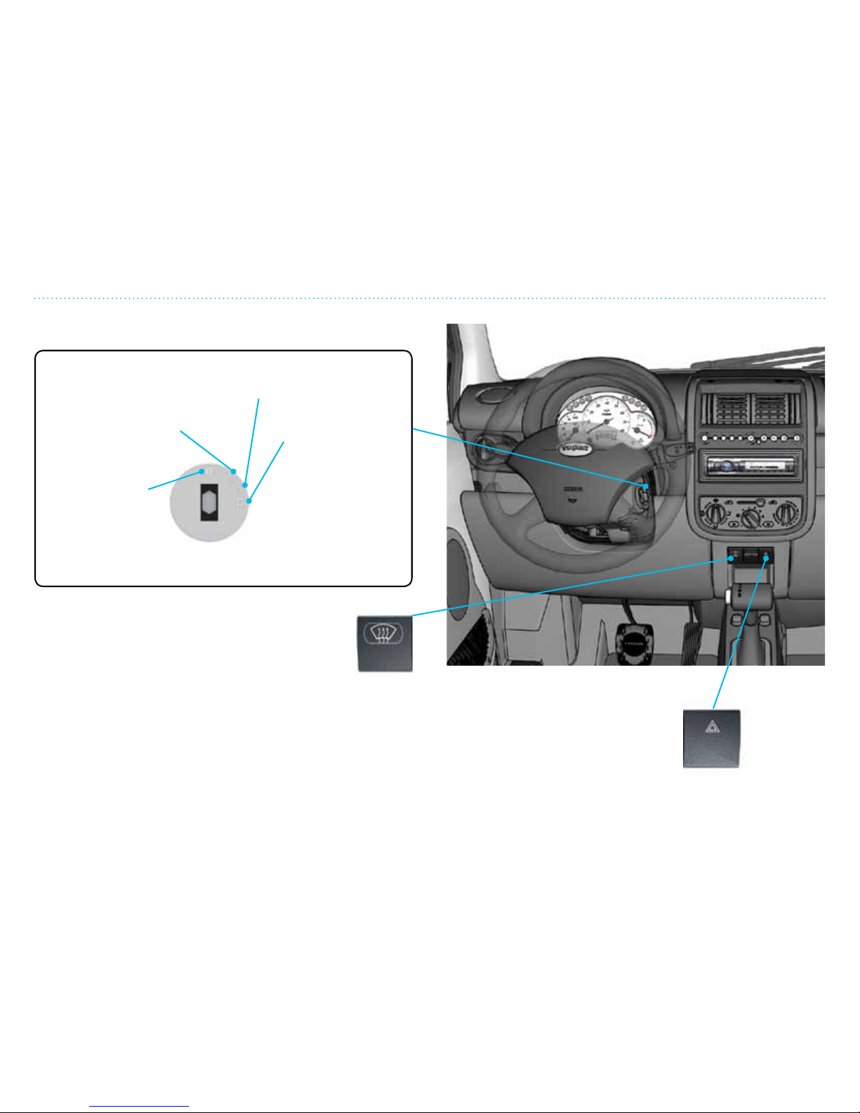
Ignition Lock
I. Turns off the motor
and other functions.
The radio can be used.
II. All electrical functions
are on. The key is in the
drive position.
III. Starts the motor
and all systems for
driving. Release
the key as soon as
the motor starts
(indicated by the
green car telltale
lamp in the warning
lamp panel). Once
released, the key
automatically
returns to position II.
0.Activates the
steering wheel
lock. The key can
be taken out.
Electric Windshield Defroster (if equipped)
This button has two positions. Pushing once will remove
dew (yellow light illuminates).This turns off after 14
minutes or when the ignition is turned off. Press twice
to manually turn off.
Pushing twice melts ice and snow (red light illuminates). This
turns off after 4 minutes or when the ignition is turned off. Push
once to manually turn off.
Emergency Hazard Switch
This switch activates all the turn signals
when the ignition is on or off. Push once
to activate and once more to turn off.
Ignition Lock and Emergency Hazard Switch
Page 36
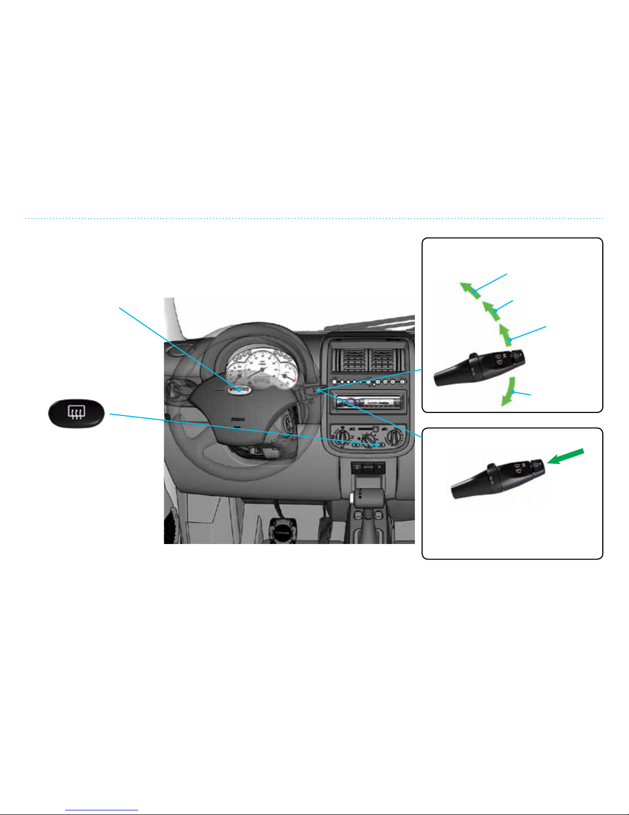
2. Overview of Instruments and Controls
212
Windshield Wiper, Defroster and Horn
Windshield Wiper Speed
Windshield Washer
Defrosting Back Window
Push the button to activate.
This removes dew/moisture
and melts thin ice or snow. The
light in the switch will stay on
as long as the heat is on. This
will turn off after 14 minutes
or when the ignition is turned
off. Push the button again to
manually turn off.
Horn
Press on the center
of the steering wheel
to beep a warning.
High speed
Normal
speed
Intermittent
function
One single
swipe
Pull the handle towards you to start
the wiper blade. It will swipe over 3
more times after the washer fluid
stops spraying.
Windshield Wiper, Defroster and Horn
Page 37
2. Overview of Instruments and Controls
213
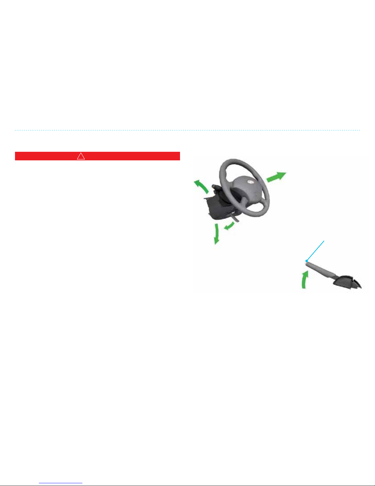
Start-up Locking System, Steering Wheel and Parking Brake
Start-up Locking System, Steering Wheel and Parking Brake
!
WARNING
Never adjust the steering wheel column while the vehicle is
in motion! Doing so may result in loss of vehicle control and
possible injury or death in the event of a collision.
THINK City is equipped with start-up locking system which is
an advanced the protection feature. The keys are coded for
each individual vehicle, and only the exact keys can be used to
start it. If you lose the keys or they are stolen, you must contact
your dealer to code new keys.
If there are large metal objects, electronic devices or other keys
kept on the same key ring, this could cause start-up diculties.
Make sure none of these items are touching the vehicle key
when you start the motor. These objects will not damage the
key but can cause problems during start-up if they are too close
to it. If you experience diculty starting up, turn the key to o
position, and hold these objects away from the key and start
the vehicle again. Be sure that your ignition key is an original
THINK City key.
Reserve keys can be bought at your dealer who can code them
for the locking system.
If one or both keys are lost or stolen, you must take the vehicle
and key(s) to the dealer for re-coding.
Steering Wheel and Parking Brake
Up
Down
Closer (if equipped)
Release the lock
Parking
brake on
The parking brake works on the back wheels. Always use the
parking brake when you leave the vehicle.
Handle for steering
wheel adjustment. Pull
the handle down to
release the steering
wheel. Move steering
wheel up or down with
both hands. Move the
handle back to the
locked position before
you drive!
Release button.
Pull the parking
brake up a bit as you
push in the release
button at the end.
Page 38

Page 39

The purpose of the climate control system in THINK City is to
assure the utmost comfort and convenience for both driver and
passenger. Remember that using the ventilation and heating fans
take energy from the vehicle’s traction battery.
3. Climate Controls
Page 40

3. Climate Controls
32
Page 41

3. Climate Controls
33
Table of Contents
Setting the Climate Controls ................................................................................................................................... 34
Fresh Air and Recirculation ....................................................................................................................................36
Recommended Settings ............................................................................................................................................ 37
Tips and Advice .............................................................................................................................................................39
Page 42
3. Climate Controls
34
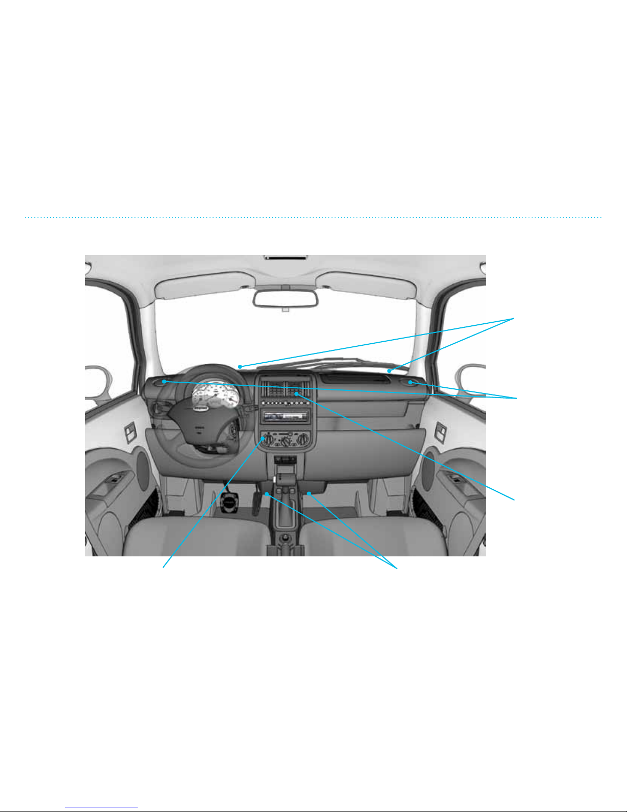
Setting the Climate Controls
Setting the Climate Controls
The various air vents
regulate the amount of
air and blowing direction
Windshield vents
keep the windshield
free of moisture
Side vents for side
windows
Center vent for
interior air
Floor vents for air
to the floor
Climate control
setting panel
Page 43
3. Climate Controls
35
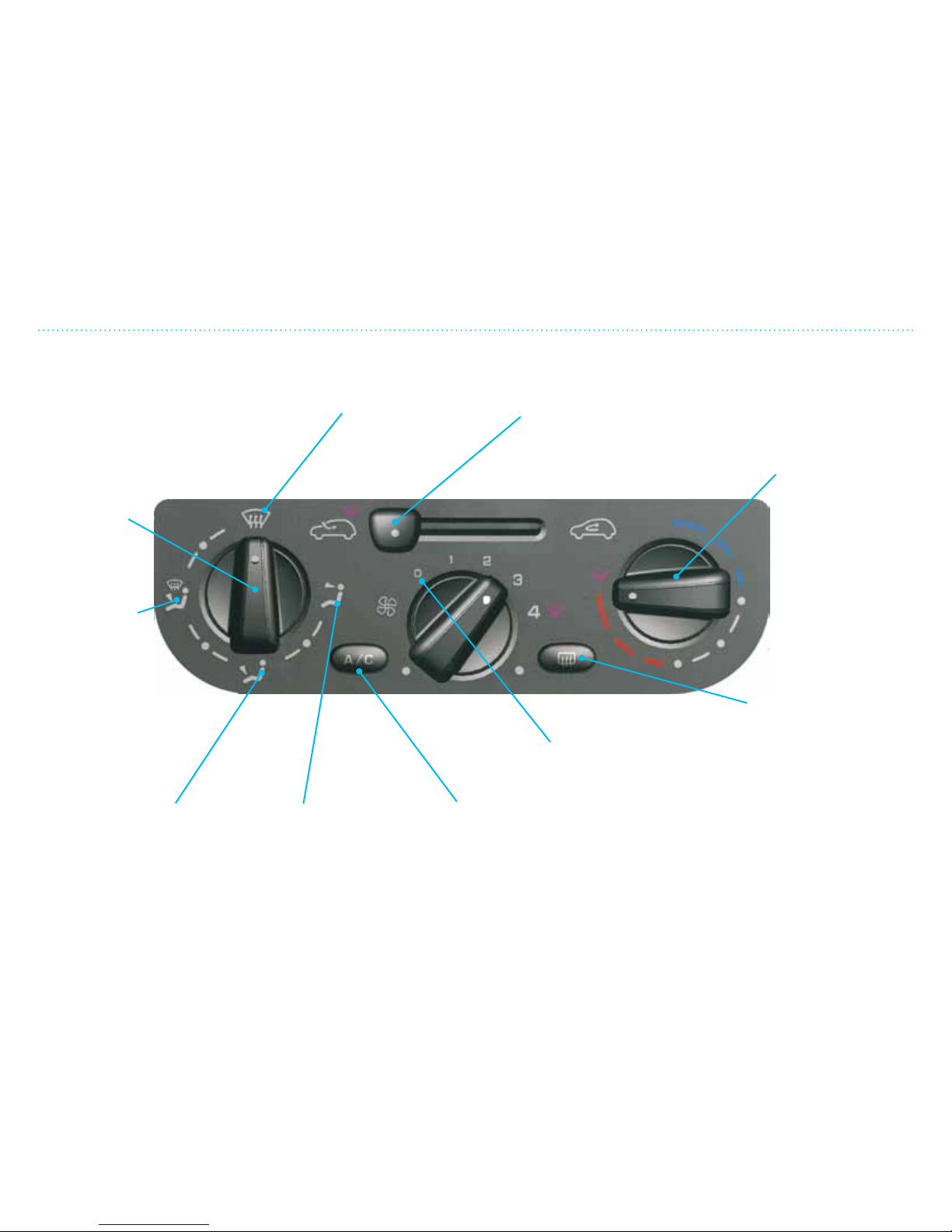
Setting the Climate Controls
If you select a position
between two symbols,
the air is distributed
accordingly
Air flow
direction
control
Air towards
the windshield
and the floor
Almost all air
towards the floor,
a little towards the
windshield
All air through the
center and side
vents
All air directed
toward windshield
Fresh air/recirculation
(see page 3-6)
Defrosting rear
windows and
electrically heated
mirrors (if equipped)
(see page 2-12)
A/C on/off switch
Temperature
control.
Heat comes from
an electric heating
element and can
therefore reduce
the distance the
vehicle can be
driven. The heating
element will stay on
unless the
temperature
control is set
at the coldest
temperature.
Temperature
setting:
Red = hot
Blue= cold
Fan speed
Fan speed 0 = no air.
At high vehicle speeds
some air can still go
through the system. Use
recirculation to avoid this.
Fan speed 4 =
maximum fan speed.
Page 44
3. Climate Controls
36
Fresh Air and Recirculation
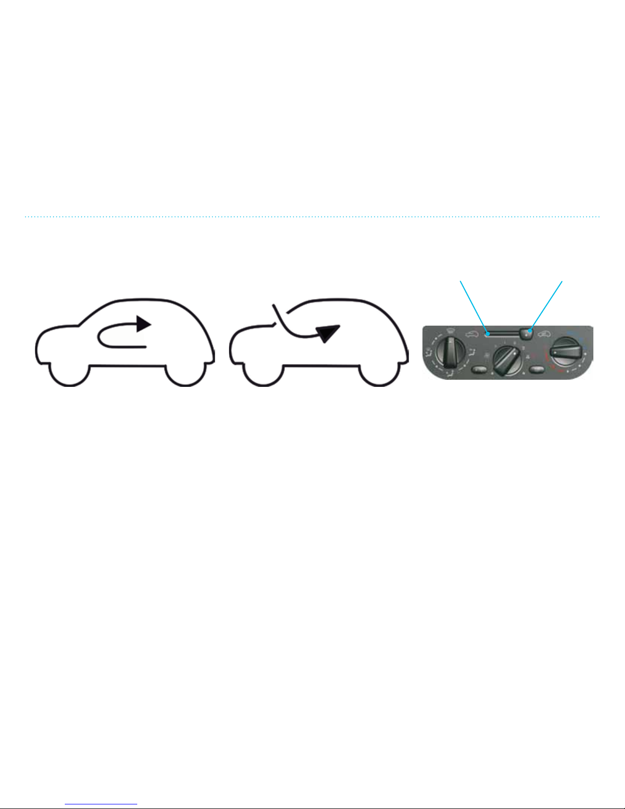
Recirculating the Air
In this case, the interior air is
recirculated and fresh air is not coming
into the vehicle.
This will stop fumes (exhaust in a
tunnel, etc.) from coming in. This also
helps the vehicle to stay warm, and is
the most energy ecient setting.
The disadvantage is that the windows
may fog up and air quality is eventually
reduced.
Fresh Air
Opening the fresh air vents allows for
better air quality and is necessary to
keep the windows from fogging up
which is oen the case in cold or humid
weather.
Setting the controls to combine
recirculated and fresh air is preferable
and also helps to save energy by
utilizing the existing interior air
temperature.
In order for the ventilation system to
work properly, the air ducts on the
vehicle must not be blocked or covered
by snow or leaves.
Fresh air Recirculation
Fresh Air and Recirculation
Page 45
3. Climate Controls
37
Recommended Settings
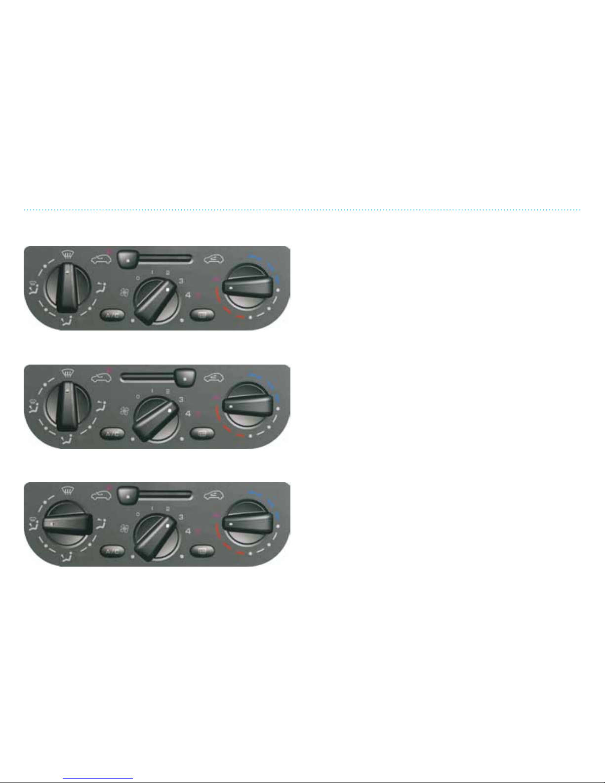
To remove mist or moisture:
Set the air direction towards the windshield, choose fresh
air on high speed (level 24) and the warmest heat setting. If
the vehicle is equipped with A/C, turn this on. If the vehicle is
equipped with electric front window defrosting (optional), turn
this on.
To remove snow/ice from the windshield:
Set the air direction towards the windshield, choose
recirculation, high fan speed (level 34) and the warmest heat
setting. If the vehicle is equipped with electric front window
defrosting (optional), turn this on.
To heat up quickly:
Set the air direction towards the windshield and oor, select
fresh air, fan speed 23 and the warmest heat setting.
Recommended Settings
Page 46
3. Climate Controls
38
Recommended Settings
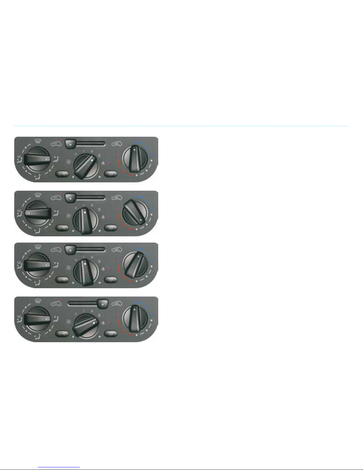
For ventilation:
Set air direction towards the interior (vent mode), choose
fresh air, adjust fan speed to suitable level and the coldest
temperature setting.
Heating in cold climate (–4ºF to 50ºF):
Set the air direction towards the windshield and oor, select
fresh air and suitable fan speed and adjust the temperature
setting to a comfortable temperature.
Cooling and ventilation at ambient conditions above 50ºF:
Set air direction towards interior (vent mode), choose fresh air,
adjust fan speed to a suitable level and set temperature to a
suitable level (0 to 180-degree knob position or blue and white
area).
Maximum cooling in hot conditions:
Set air direction towards interior (vent mode), choose
recirculated air, choose high fan speed (34) and set
temperature knob to max cool.
NOTE: The interior air quality will deteriorate if the air
recirculation setting is on too long; a recommendation is to
switch to fresh air for 12 minutes every 20 minutes.
Page 47

3. Climate Controls
39
Tips and Advice
Tips and Advice
!
CAUTION
Do not place objects on top of the dashboard as these can fly
through the air when braking or in an accident. Objects on
the dashboard can also block the stream of air or fall into the
air vents and damage the ventilation system. They can also
reduce visibility.
In humid weather, the defroster function (air blowing toward
the windshield) should be selected before starting to drive. This
will reduce the chance of dew and moisture building up on the
windshield in the rst few minutes. Eventually the settings can
be changed.
NOTE: Ensure that snow, ice and leaves in the grill and the hood
are removed or the heating system’s air intake ducts will be
blocked.
Wash the vehicle’s windows regularly both inside and out. This
removes any greasy lm that builds up and also absorbs extra
moisture.
While driving in cool weather you can choose recirculation
which helps to heat up the interior air more quickly. Select fresh
air as soon as the interior is warm to avoid dew and moisture on
the windows.
NOTE: The interior air quality will deteriorate if the air
recirculation setting is on too long, so use it for shorter periods.
Using the ventilation system will reduce the distance the
vehicle can drive so use the maximum settings only when
necessary.
If the vehicle has the electrically heated windshield (if
equipped), you can increase the driving distance by using this
to remove ice and snow instead of the heating and ventilation
system.
Page 48

Page 49

THINK City – a safe, small vehicle. THINK City has been
developed in cooperation with leading automobile
industries involved in vehicle safety.
The collision tests and endurance tests have been
conducted in accordance with recognized standards in the
automotive industry.
In this chapter you will nd information regarding safety
equipment and practical advice on vehicle operation.
4. Driving and Safety
Page 50

4. Driving and Safety
42
Page 51

4. Driving and Safety
43
Table of Contents
Important Safety Systems ........................................................................................................................................44
Safety Rules.....................................................................................................................................................................45
Recommended Settings ............................................................................................................................................ 47
Head Restraints .............................................................................................................................................................48
Economical Driving and Energy Tips .................................................................................................................49
Gear Selector Positions ............................................................................................................................................410
Antilock Brake System (ABS ) ................................................................................................................................ 411
Driving Tips .................................................................................................................................................................. 412
Electronic Stability Program (ESP) ..................................................................................................................... 413
Parking Brake .............................................................................................................................................................. 414
Safety Belts .................................................................................................................................................................... 415
Air Bags ........................................................................................................................................................................... 416
Children and Safety ................................................................................................................................................... 419
Luggage Compartment and Storage...................................................................................................................423
Driving with Roof Racks and Ski Box ............................................................................................................... 424
Avoiding Roll Over .................................................................................................................................................... 424
Driving in Water, Winter Driving and Using Snow Chains .......................................................................425
Towing ........................................................................................................................................................................... 426
Wheels and Tires ........................................................................................................................................................427
Changing a Wheel...................................................................................................................................................... 428
Tire Pressure Monitoring System (TPMS) ..................................................................................................... 429
Jump Start — Start Cables ........................................................................................................................................ 431
Page 52
4. Driving and Safety
44
Important Safety Systems
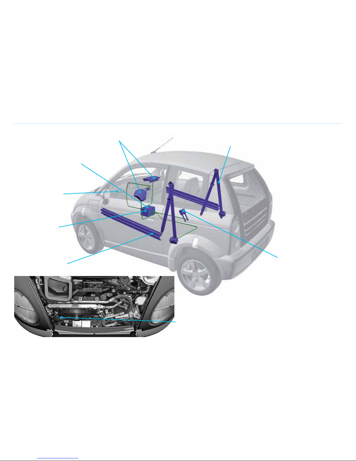
Control unit for safety
systems. Sends signals to
the active components
in the safety system.
Warning lamp in
instrument cluster.
Air bags (2-stage) 3-point safety belt
with belt adjusters
Pre-tensioner safety
belt buckles with sensor
Inertia sensor. THINK City is equipped with an inertia sensor in
front of the motor. The sensor sends a signal to the traction
battery that cuts the power from the traction battery in case
of an impact.
THINK City is equipped
with a safety system for
driver and passenger.
To provide the best
protection in an accident,
wear the safety belts at
all times.
Steel reinforcement
in the doors.
Front collision
sensor.
Measures
deceleration
during an
accident.
Important Safety Systems
Page 53
4. Driving and Safety
45
Safety Rules
Safety Rules
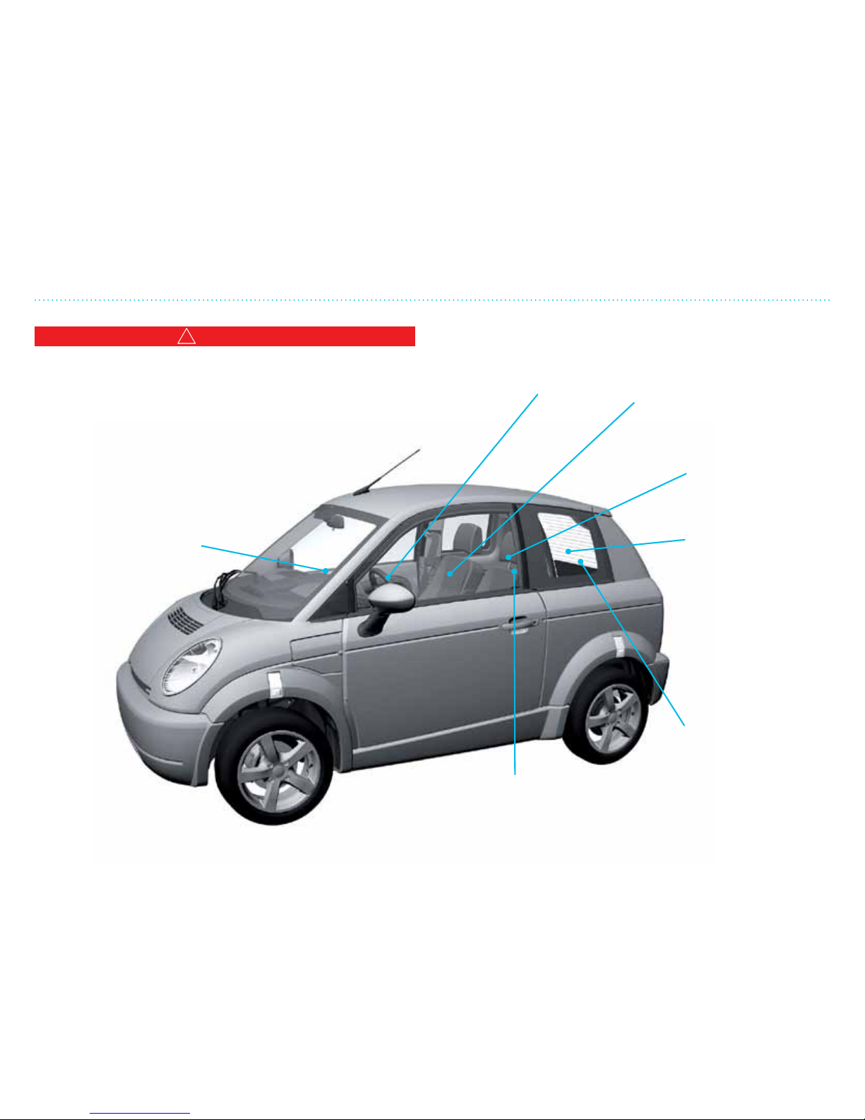
Check the following regularly:
• Anti-freeze level
• Brake uid
• Power steering uid
• Windshield wiper/washer uid level
• Tire treads and air pressure
• Lights
Keep the head
lamps clean.
Strong, bright
lights are
important for
safety
(see page 5-6)
Remove the battery charging cable before getting into the
vehicle. Take it with you so you can use it in other places.
NOTE: It is recommended that the battery charging cable
is disconnected from the vehicle first and then from the
electrical outlet.
Lock/unlock with key fob
(see page 1-18).
Use recommended
quality tires. Never
let the tread go
under the minimum
depth. Check for
proper air pressure
(see page 5-20).
Good tires are
essential
for safe driving.
Check that the
windows are clean
and ice/snow free.
Make sure the air intake area is
clear of ice/snow/leaves.
Page 54
4. Driving and Safety
46
Safety Rules
!
WARNING
Children 12 years old and under can be killed or injured by the
air bag. Never put a rear-facing child seat in the front unless
the air bag system is turned OFF using the air bag disconnect
switch. Sit as far back as possible from the air bag. Always use
safety belts and/or the correct child restraints. Air bag warning
information is printed on the driver and passenger sun visors.
Do not allow children to sit
on a passenger’s lap while
driving. The passenger
cannot protect the child in
a collision (see pages 4-19,
4-20, 4-21 and 4-22).
Adjust the seats, mirrors and
steering wheel so you are
comfortable and have good
visibility (see page 4-7).
Check that child safety
equipment, if installed, is
properly mounted (see pages
4-19, 4-20 and 4-21).
Drive with the seat back
straight up and the
safety belt fastened
low and tight over your
hips (see page 4-15).
Secure/tie-down items
stored/transported
in the luggage
compartment. Loose
objects can injure
people in the vehicle
during unexpected
quick braking or a
collision (see page
4-23).
Passengers are only
allowed to sit in the
back if the vehicle is
equipped with rear
seats and safety belts.
Passengers and the driver
are required to wear
safety belts at all times
(see page 4-15).
Page 55
4. Driving and Safety
47
Recommended Settings
Recommended Settings
!
WARNING
• Never adjust the steering wheel or the seat/headrest while
the vehicle is in motion! Doing so may result in loss of
vehicle control and possible injury or death in the event of a
collision.
• Do not sit too close to the air bag. The National Highway
Traffic Safety Administration (NHTSA) recommends a
minimum distance of 10 in. (25 cm) between an occupant’s
chest and the driver’s air bag module.
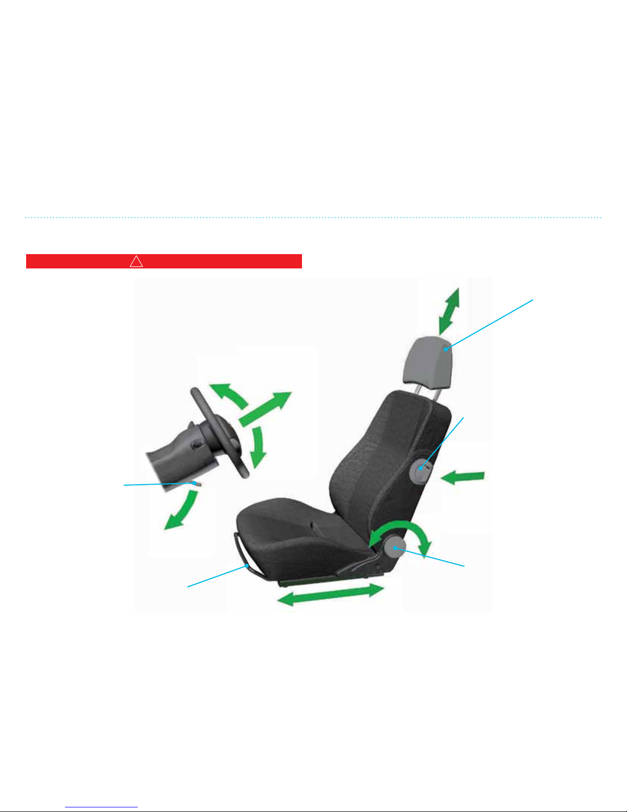
It is important for safety reasons
to sit in a comfortable position
so be sure to adjust the seat
and steering wheel so you
have full control and
good visibility.
Handle for adjusting
the steering wheel
to the desired angle.
Press the handle
down and move the
steering wheel up or
down and then lock it
in place by lifting the
handle up again.
Handle to move the seat
forward/backward. Lift the
handle and slide the seat to the
desired position.
Adjusts the angle of the
seat back. Rotate the knob
clockwise or counterclockwise
to the desired position.
Knob to flip/slide the seat
forward for easy access to the
luggage compartment.
To return the seat back to its
original position, slide the seat
back and flip the seat back
rearward until you hear a click.
The headrest should be
adjusted to your height
(directly behind your head).
It is adjusted by pulling the
headrest straight up or pushing
it down into the seat back.
(if equipped)
Page 56
4. Driving and Safety
48
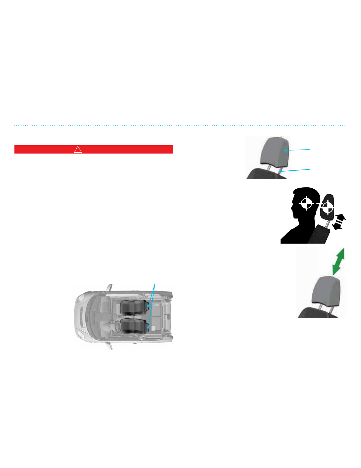
Head
restraint
Head restraint
stalks
Components of Head
Restraints
Adjustment
Adjust the head restraint so the
center is level with the center of
the seat occupant’s ears. THINK
City’s head restraints are not meant
to be removable. In the event
the head restraints are removed,
please ensure that they are
correctly installed prior to using
the vehicle.
To raise the head restraint, pull it up.
To lower, push the head restraint down.
Head Restraints
Head Restraints
!
WARNING
• Head restraints supplement the other vehicle safety
systems. They may provide additional protection against
injury in certain rear-end collisions. All occupants, including
the driver, should not operate a vehicle or sit in a vehicle’s
seat until the head restraints are placed in their proper
positions in order to minimize the risk of neck injury in the
event of a crash.
• Adjust the head restraints properly. Check the adjustment
aer someone else uses the seat. Do not attach anything to
the head restraint stalks or remove the head restraint. Do
not use the seat if the head restraint has been removed. If the
head restraint was removed, reinstall and properly adjust
the head restraint before an occupant uses the seating
position. Failure to follow these instructions can reduce the
effectiveness of the head restraints and may increase the
risk of serious injury or death in a collision.
Seating Positions with Head Restraints
The illustration shows
the seating positions
equipped with head
restraints. All of the
head restraints are
adjustable.
Head restraint
Page 57
4. Driving and Safety
49
mph
10
0
100
80
60
40
20
0
20
30
40
50
60
70
80
0
90
100
110
120
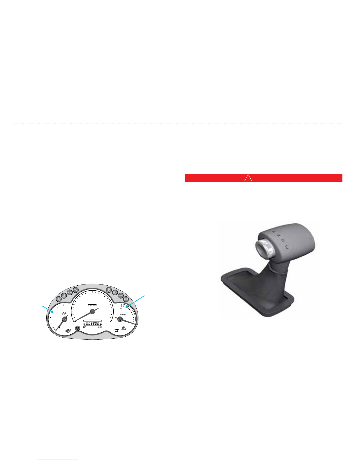
Economical Driving and Energy Tips
Economical Driving and Energy Tips
To achieve maximum driving distance you should:
• Use position E (eciency) on the gear selector when
possible.
• Use the recommended tire air pressure.
• Keep the vehicle weight as light as possible.
• Avoid driving constantly with roof racks (if equipped).
• Do not accelerate quickly.
• Maintain a moderate speed.
• Drive as smoothly as possible.
• Limit the use of the heating system.
• Remember to connect the charge cable to the electrical
outlet when the vehicle is not in use. The battery will then be
fully charged for your next trip.
See the Battery Manual for information on the battery. Both
driving style and use of heating and other electrical equipment
aects the distance the vehicle can go. Instruments in the
vehicle provide information about the driving distance and
energy usage. See Chapter 2 for more information.
Regenerative Brakes
THINK City is equipped with a motor brake that feeds energy
to the battery for recharging, and at the same time slows the
vehicle down. When the accelerator is released, this goes into
operation.
!
WARNING
Note that if you are not careful when releasing the accelerator,
the motor brake can lock the front wheels during extremely
slippery road conditions. This could happen, especially when
the gear shier is in E (EFFICIENT DRIVING). So use extreme
caution when driving on slippery road conditions.
If the battery is fully charged, the regenerative braking eect
will be reduced to avoid over charging. This eect will also
disengage if the ABS is activated.
Power
gauge.
Displays
the energy
level of the
traction
battery.
Economy
gauge
(energy
usage)
Page 58
4. Driving and Safety
410
Gear Selector Positions
Gear Selector Positions
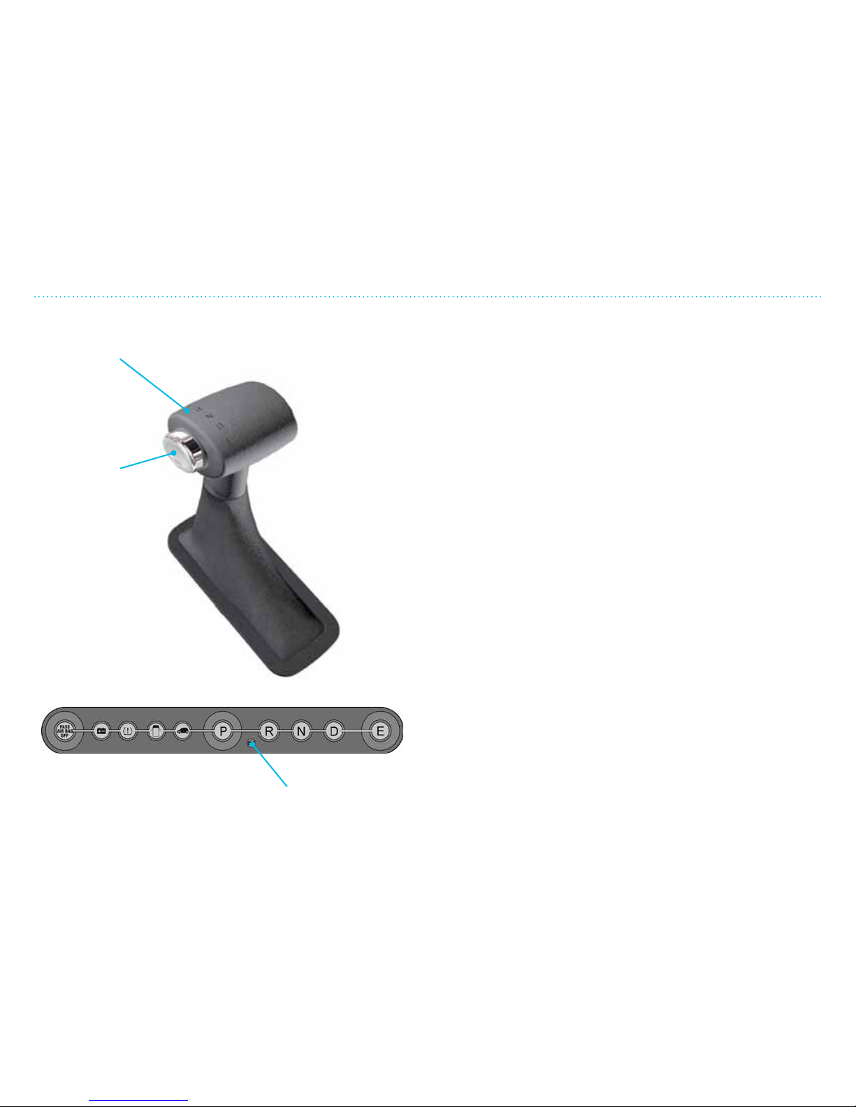
The brake pedal must be depressed before the release button
is pushed in to move the gear selector from P (PARK). Keep the
brake pedal depressed to prevent the vehicle from moving.
P (PARK) —
The vehicle must be standing still for the gear
selector to move into P. The gear selector in P locks the gear box
and stops the front wheels from turning. The gear selector must
be in P for the ignition key to be removed. If the doors open
when the gear selector is not in P, a warning signal will beep.
Also, the gear selector cannot be shied into or out of P if the
key is not turned on.
R (REVERSE) —
With the gear selector in R, the vehicle will
move backward. Apply the brakes if necessary.
N (NEUTRAL) —
The vehicle can be started without the gear
engaged (the vehicle can roll). Apply the brakes if necessary.
D (DRIVE) —
When the gear selector is in D, the vehicle will
move forward. Apply the brakes to stop the vehicle. This is
the recommended gear when driving on highways and open
roads. The regenerative brakes will go into eect as soon as the
accelerator is released (if the battery is almost fully charged, the
regenerative braking eect will be limited).
E (EFFICIENCY DRIVING) —
When the gear selector is in E, the
vehicle will move forward. The power output is limited to 20
kW and the level of regeneration is higher. This allows for the
maximum driving distance and is recommended when full
power is not required (downtown city driving or slow trac).
Gear selector
Release
button
Indicator shows that gear selector is locked
until the brake pedal is pressed down.
Gear Selector Positions
Page 59
4. Driving and Safety
411
Antilock Brake System (ABS)
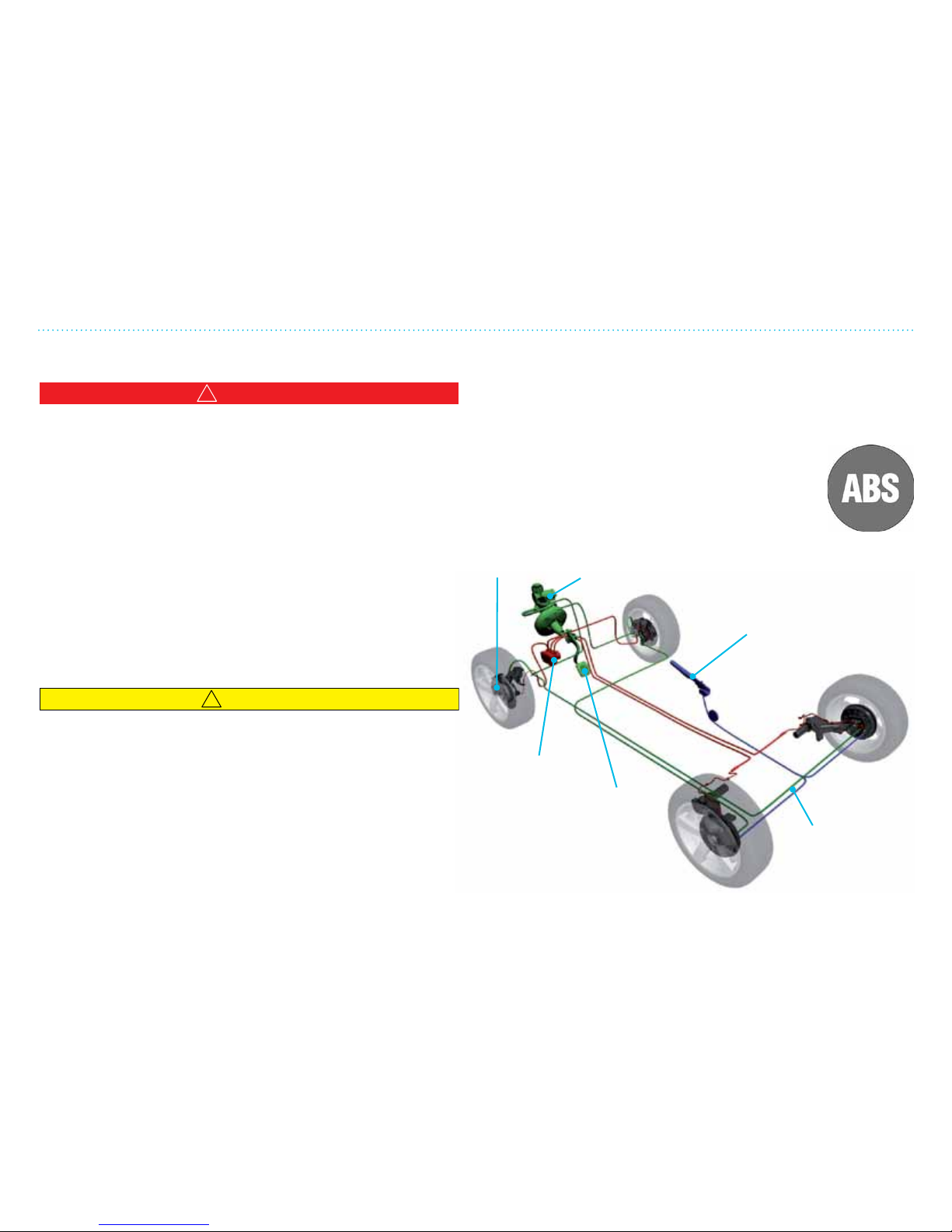
The vehicle’s power brakes produce a vacuum when the
brakes are applied. This is done with the help of an electric
pump. When the brake pedal is applied, the electric pump will
make a sound – this is normal.
Warning Lamp for ABS Brakes
This warning lamp will illuminate briey when
the ignition is started, before the motor starts. It
should then go out. If there is a fault in the ABS,
the warning lamp will be lit continuously. Even
if there is a problem in the ABS,
the normal braking system
will work (including the
regenerative braking system).
Antilock Brake System (ABS)
!
WARNING
• The antilock brake system (ABS) cannot prevent the natural
laws of physics from acting on the vehicle, nor can it increase
braking or steering efficiency beyond that afforded by the
condition of the vehicle brakes and tires or the traction. The
ABS cannot prevent all accidents, including those resulting
from excessive speed in turns, following another vehicle
too closely, or hydroplaning. Only safe, attentive and skillful
driving can prevent accidents. The capabilities of an ABSequipped vehicle must never be exploited in a reckless or
dangerous manner which could jeopardize the user’s safety
or the safety of others.
• Do not take driving risks and hope that ABS will correct
judgment errors. It is always your responsibility to drive
with due care and attention.
!
CAUTION
Moisture and road salt can reduce the efficiency of the
brakes. When driving in wet conditions or aer washing the
vehicle, the brake discs can get wet and the efficiency of the
brakes could be reduced temporarily. Test the brakes aer
such conditions by pressing the brake pedal lightly. This
will produce heat which reduces the moisture. This test is
especially important aer washing the vehicle in winter at or
below freezing conditions.
Brake
discs
ABS control
unit
Brake pedal
Electric power
brake
Parking brake
Electronic
control signals
Page 60
4. Driving and Safety
412
Battery
Antilock Brake System (ABS)
Battery
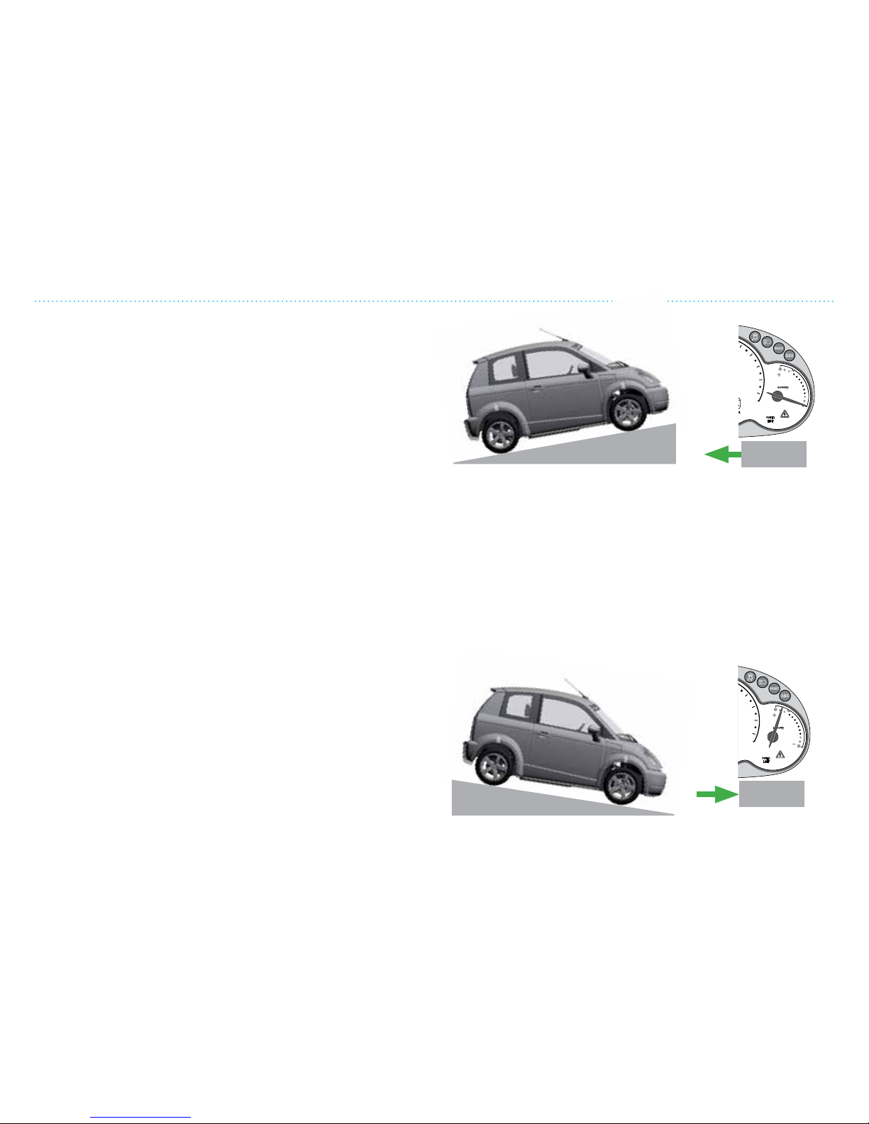
While driving the vehicle, whenever the accelerator is not
depressed, the motor will act as generator and will create
energy that charges the battery. This is more pronounced when
driving downhill or when driving in EFFICIENCY DRIVING
mode. This is called regenerative braking and helps maximize
your driving range. By anticipating your stops and simply
removing your foot from the accelerator to slow down, you can
take advantage of the energy gained from regenerative braking.
80
0
90
100
110
120
The ABS monitors the speed of the wheels. If one of the wheels
gets blocked during braking, the braking power will adjust itself
so that the wheel does not lock up. The wheels will continue
to rotate freely, allowing you to steer the vehicle even in an
emergency situation.
When the ABS cuts in, there will be a pulsating movement in the
brake pedal. This is normal and indicates that the ABS brakes
are working as they should. It is not uncommon to hear noise
from the braking system both during braking and when starting
up. This can be caused by dust, moisture, heat, cold, salt or dirt.
If there is a constant “metal upon metal” sound when braking,
have the brakes checked by your dealer. Dealer should also be
contacted if there is repeated vibration in the steering wheel
during braking.
Driving Tips
When THINK City starts and drives, energy from the battery is
used. The greater the speed or steeper uphill, the more energy
is required. Fast acceleration and erratic driving uses more
energy than smooth and stable driving.
0
90
100
110
120
Page 61

4. Driving and Safety
413
Electronic Stability Program (ESP)
Electronic Stability Program (ESP) (if equipped)
!
WARNING
If the ESP warning lamp in the instrument cluster flashes,
proceed as follows:
• While driving, apply as little throttle as possible.
• While driving, ease up on the accelerator pedal.
• Adapt your speed and driving style to the prevailing road
conditions.
Failure to observe these guidelines could cause the vehicle to
skid. The ESP system cannot prevent accidents resulting from
excessive speed.
!
WARNING
The ESP system cannot prevent the natural laws of physics
from acting on the vehicle, nor can it increase the traction. The
ESP system cannot prevent accidents resulting from excessive
speed in turns or hydroplaning. Only safe, attentive and
skillful driving can prevent accidents. The capabilities of an
ESP system must never be exploited in a reckless or dangerous
manner which could jeopardize the user’s safety or the safety
of others.
Your vehicle may be equipped with the Electronic
Stability Program (ESP). If equipped, the ESP system
is active as soon as the vehicle is turned on and it
monitors the vehicle’s traction and handling. The
ESP system detects when a wheel is spinning or if the vehicle
starts to skid. Once recognized, the ESP system stabilizes the
vehicle by applying brakes to the appropriate wheel and also by
limiting the power output to the front wheels. The ESP warning
lamp in the instrument cluster ashes whenever an ESP event
occurs.
The ESP warning lamp is also an ESP fault detection telltale
lamp. The ESP warning lamp in the instrument cluster briey
illuminates when you switch on the vehicle and goes out when
the vehicle is running. If the lamp illuminates continuously
while driving, the ESP system is not fully operational and the
vehicle should be checked by the dealer as soon as possible.
Page 62
4. Driving and Safety
414
Parking Brake
Parking Brake
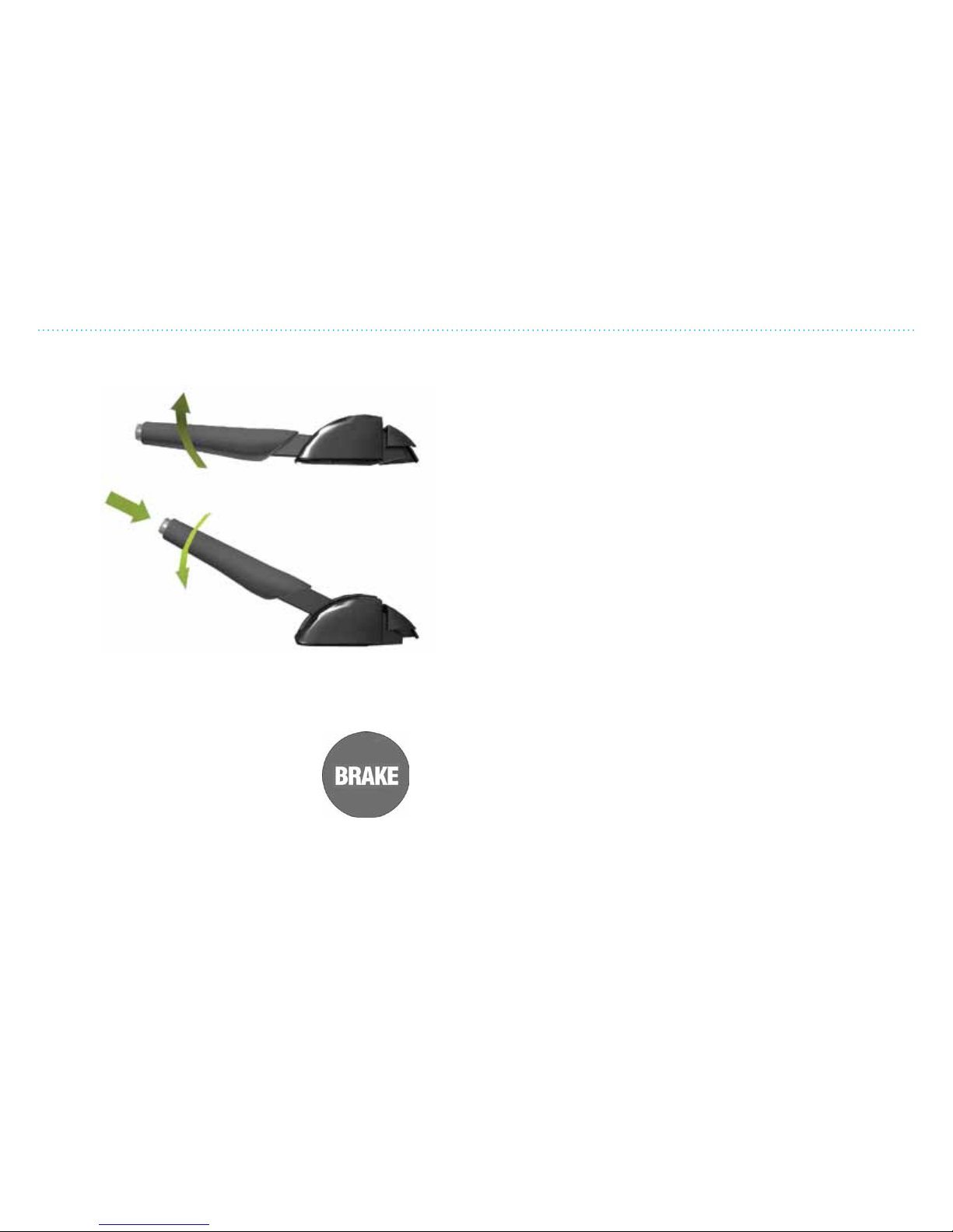
Engage
Disengage
Always use the parking brake when the vehicle is parked. Pull
the lever upward. The parking brake works on the rear wheels
and should be engaged aer 23 “clicks”. If not, this must be
checked and corrected by your dealer.
Warning lamps for the braking system
will illuminate when the parking brake is on.
The parking brake is disengaged by pushing the button at the
end of the lever, and pulling up slightly then moving down. The
parking brake can be used as an emergency brake when the
vehicle is moving. The parking brake works only on the rear
wheels and the vehicle will therefore have a longer braking
distance and the vehicle will feel quite dierent than during
normal braking.
Page 63
4. Driving and Safety
415
Safety Belts
Release
button
Safety Belts
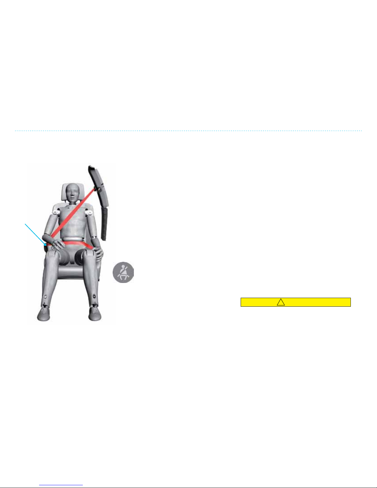
THINK City is equipped with combined lap and
shoulder belts (3-point safety belt).
Fastening the safety belts:
1. Pull the safety belt slowly out and over your
shoulder. Insert the tongue of the safety belt
securely into the buckle.
2. Tighten the safety belt by pulling on the
shoulder strap so that the lap belt ts snugly.
3. Push on the release button to unfasten the
safety belt.
Check that the safety belt:
• is not twisted
• is securely fastened in the buckle – listen for
a sharp snap.
The warning lamp for safety belts will
illuminate and make a warning beep if
the vehicle is started and the safety
belts are not fastened.
Safety Belt Locking Modes
Normal sensitive mode:
This is the normal retraction mode and
allows movement and slow adjustments. If
the driver brakes suddenly or turns a corner
sharply, or if the vehicle receives an impact of
approximately 5 mph (8 km/h) or more, the
combination safety belts will lock to help stop
the driver and passengers from being thrown
forward.
Automatic lock mode
The passenger side has the automatic lock
retractor (ALR) (this is not available on the
driver safety belt). This mode must be used
any time a child safety seat is installed in the
passenger front seat using the passenger
safety belt (see page 421).
Using the automatic lock mode:
1. Pull the safety belt all the way out.
2. Buckle the safety belt.
3. Let the safety belt retract until it is tight.
There will be clicking sounds which
means that the safety belt is locked and
cannot be pulled any further out.
To release automatic locking:
• Loosen the safety belt and let it fully
retract. The automatic locking is now fully
disengaged and normal sensitive mode is
activated.
!
CAUTION
If the vehicle has been in an accident and the
air bags deployed or the safety belt locked,
the vehicle must be taken to your dealer to
inspect/repair/replace the safety restraints.
Do not attempt to repair these yourself.
Page 64
4. Driving and Safety
416
Air Bags
Air Bags
!
WARNING
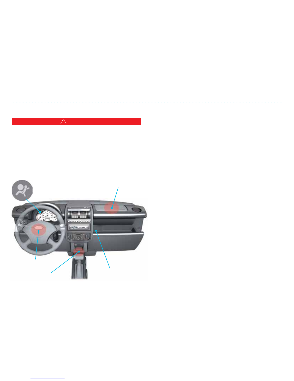
The vehicle is equipped with an air bag and lap/shoulder
belt at both front outboard seating positions. All occupants,
including the driver, should always wear their safety belts
whether or not an air bag is also provided, in order to minimize
the risk of severe injury or death in the event of a crash. The
air bag is a supplemental restraint at these seating positions
providing additional protection in certain types of collisions
only — they do not replace the need to wear a safety belt.
General Information
Air bags are an integral part of the vehicle’s safety system. The
control unit will analyze data received from the collision and
safety sensors to determine if the air bags should be released.
Air bags are designed to be released only in a frontal collision
or another type of collision severe enough to activate them.
Activation of the air bags is accompanied by a loud noise; air
bags inate rapidly to reduce the crash force before deating
in a controlled manner. This happens in a matter of tenths of
seconds.
How the System Works
Operation of the air bag system depends on the rate at which
your vehicle decelerates as a result of a collision. In the event
of a collision, the air bag control unit monitors the rate of
deceleration to determine whether the air bags should be
deployed.
When deployed, air bags inate rapidly, with considerable force
accompanied by a loud noise. The deployed air bag, together
with the safety belt restraint system, limits the movement of the
occupants, thereby reducing the risk of injury to the head and
upper torso.
The air bag system is not designed to deploy as a result of:
• Rear collisions
• Minor front impacts
• Minor side impacts
• Heavy braking
• Driving over bumps or potholes
Air bag
(2-stage)
Air bag
(2-stage)
Air bag control unit
Switch for
disengaging
the passenger
side air bag
(under the
plastic panel)
Page 65

4. Driving and Safety
417
Air Bags
!
WARNING
• The air bags deploy with considerable speed and force and
there is risk of injury such as facial abrasions, fractures,
injury to the facial area or eyes and possible internal injury.
To limit these injuries, ensure that occupants are correctly
seated, with the seat as far back as is practical, and are
wearing safety belts.
• When air bags are deployed, a powdery residue is emitted;
this may cause eye and skin irritation if exposed too long.
Wash with soap as soon as possible. Several components in
the air bag system heat up during deployment; do not touch
these components directly aer deployment, allow time for
cooling.
• The National Highway Traffic Safety Administration
(NHTSA) recommends a minimum distance of 10 in. (25 cm)
between an occupant’s chest and the driver’s air bag module.
Obstruction of Air Bags
!
WARNING
• Do not allow passengers to obstruct the operation of the air
bags by placing feet, knees or any other part of the body, or
any loose objects in contact with, or in close proximity to, an
air bag module.
• Do not attach or position items on an air bag cover, which
could interfere with the inflation of the air bag or be
propelled inside your vehicle and injure occupants.
Deployment of Air Bags
!
WARNING
In the event the air bags are deployed, the vehicle must be
taken to an authorized THINK NA dealer to check/repair/
replace the safety restraint systems. Do not attempt to repair
these systems yourself.
NOTE: This vehicle is subject to NHTSA Temporary Exemption
No. EX 0902, from S14.5.2, S15, S17, S19, S21, S23, and S25 of
FMVSS 208; the so-called advanced air bag requirement.
Air Bag Warning Indicator
If there is a fault in the air bag safety system,
the warning lamp will blink or illuminate
continuously or it may not illuminate at all
when the ignition is turned on. In such cases,
the air bag must be checked by your dealer.
Page 66
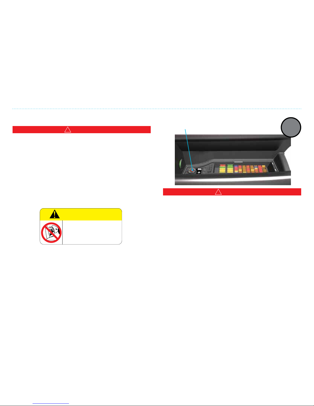
4. Driving and Safety
418
Air Bag Warning Labels
!
WARNING
• The vehicle should not be driven if warning signals/faults
in the safety restraint system, safety belts or air bags are
indicated in the control module.
• Children 12 years old and under can be killed or injured by
the air bag. Never put a rear-facing child seat in the front
passenger seat, unless the air bag system is turned OFF. Sit
as far back as possible from the air bag. Always use safety
belts and/or the correct child restraints. Air bag warning
information is printed on the driver and passenger sun
visors.
WARNING
DEATH or SERIOUS INJURY can occur
Child ren 12 a nd unde r can b e kille d by th e air b ag
The B ACK SEAT i s the s afest p lace fo r child ren
NEVER put a rear-faci ng chil d seat in front unless
air b ag is o ff
Sit a s far b ack as possibl e from t he air bag
ALWAYS us e SEAT BE LTS and CH ILD RES TRAINTS
575. 0040
Deactivating the
passenger air bags
A warning lamp on the center
stack display will illuminate when
the air bag is deactivated.
Deactivating the Passenger Air Bag
The passenger side air bag of the vehicle can be deactivated
(turned o) using the ignition key. The switch is beside the fuse
box over the passenger side foot-well.
!
WARNING
The air bag on the passenger side should always be
deactivated when:
• An infant less than 1-year-old is carried in a front-facing/rearfacing child seat
• A child 12 years old or under is riding in the front passenger
seat
Always ensure that the passenger air bags are re-activated in
all other circumstances except the ones mentioned above (or
according to a medical doctor as regards some individuals like
those of very small stature or with certain medical conditions).
Failure to do so may result in death or serious injury in the
event of a collision.
PASS
AIR BAG
OFF
Air Bags
Page 67

4. Driving and Safety
419
Children and Safety
Safety Seats for Children
!
WARNING
• Always ensure your child is secured properly in a device
that is appropriate for their height, age and weight. Failure
to properly secure children or properly secure the child
restraints and follow these instructions and guidelines may
result in an increased risk of serious injury or death to your
child.
• All U.S. states and territories require that infants and small
children be restrained in an approved child restraint at all
times while the vehicle is being operated.
!
WARNING
Children 12 years old and under can be killed or injured by
the air bag. THINK does not recommend carrying a rearfacing child restraint seat in the front seat even with the
passenger air bag turned off. For more information, refer to
the air bag warning information that is printed on the driver
and passenger sun visors. Failure to follow the warnings and
instructions for proper use and installation of child restraints
could result in serious injury or death of a child or other
passengers in a sudden stop or collision. Please follow these
precautions to ensure maximum safety:
• Sit as far back as possible from the air bag.
• Always use safety belts and/or the correct child restraints.
• Never let a child stand or kneel on any seat and do not
allow a child in the cargo area. The child could be seriously
injured or killed in a sudden stop or collision.
• Do not put a safety belt around both a child and another
passenger.
• Infants and children should never be held on anyone’s lap.
• Always carefully follow the instructions and warnings
provided by the manufacturer of any child restraint to
determine if the restraint device is appropriate for your
child’s size, height, weight or age.
• Follow the child restraint manufacturer’s instructions and
warnings provided for installation and use in conjunction
with the instructions and warnings provided by the vehicle
manufacturer.
Page 68
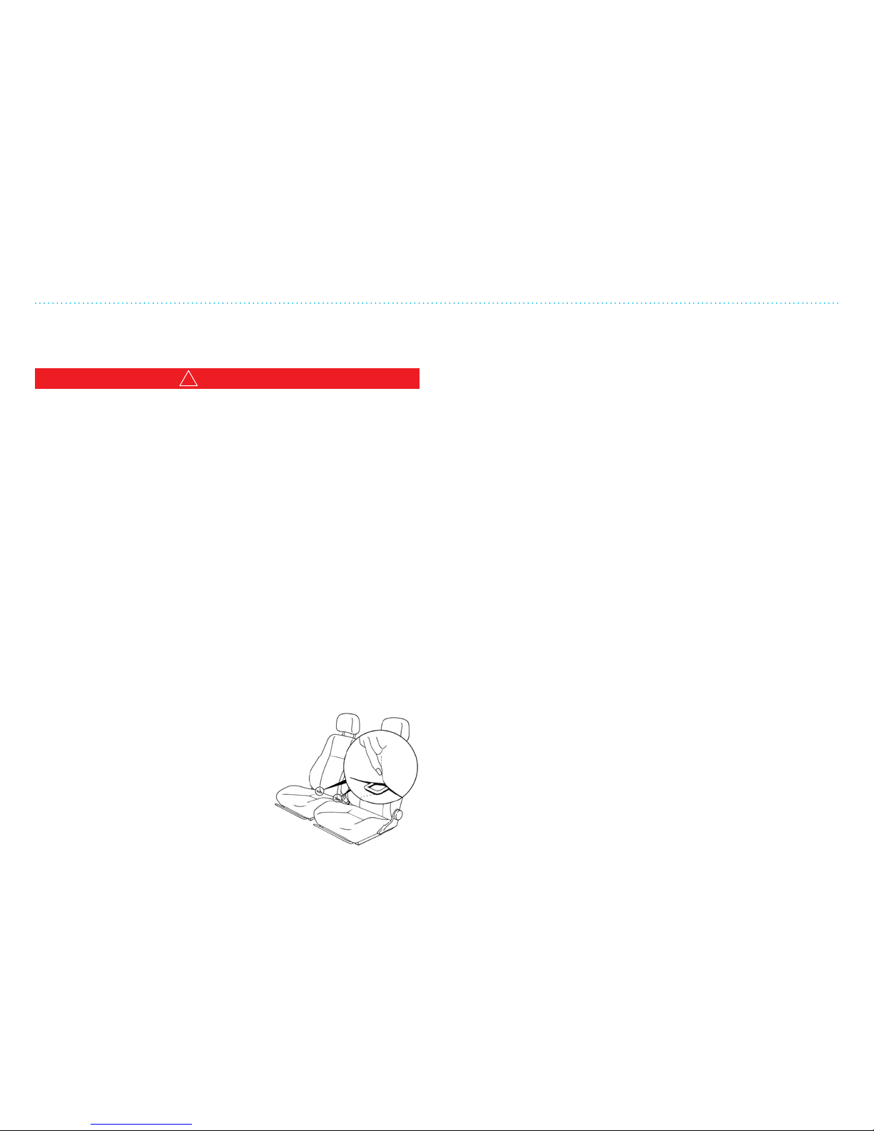
4. Driving and Safety
420
Children and Safety
Child Seat Installation Using the LATCH (Lower Anchors
and Tethers for CHildren) System
!
WARNING
Attach the LATCH system compatible child restraints only at
the front passenger position. Always inspect the lower anchors
by inserting your fingers into the lower anchor area, making
sure there are no obstructions over the anchors. Failure to
follow the warnings and instructions for proper use and
installation of child restraints could result in serious injury
or death of a child or other passengers in a sudden stop or
collision.
This vehicle is equipped with a universal child restraint anchor
system, referred to as the LATCH (Lower Anchors and Tethers
for CHildren) system in the front passenger seat. This system
may also be referred to as the ISOFIX or ISOFIX-compatible
system. With this system, you do not have to use a vehicle seat
belt to secure the child restraint. Some child restraints include
rigid or webbing-mounted attachments that can be connected
to these anchors. If you do not have a LATCH-compatible child
restraint, the vehicle seat belts must be used to secure the child
seat.
The LATCH lower anchors are located
at the rear of the seat cushion near the
seat back. LATCH compatible child
restraints include two rigid or webbingmounted attachments that can be
connected to the two lower anchors located at front passenger
positions in your vehicle.
Follow these steps to install a forward-facing child restraint
using the LATCH system:
1. Move the seat to the rearmost position.
2. Position the child restraint on the seat. The back of the child
restraint should be secured against the vehicle seat back.
3. Secure the child restraint anchor attachments to the
LATCH lower anchors. Check to make sure the LATCH
attachment is properly attached to the lower anchors. For
child restraints that are equipped with webbing-mounted
attachments, remove any additional slack from the anchor
attachments.
4. If the child restraint is equipped with a top tether strap,
route the top tether strap and secure the tether strap to
the tether anchor point. The tether anchor point can be
found on the oor of the cargo compartment behind the
front passenger seat. Adjust the head restraints if needed.
Tighten the tether strap according to the manufacturer’s
instructions to remove any slack.
5. Aer attaching the child restraint, test it before you place
the child in it. If the restraint is not secure, tighten the
LATCH attachment as necessary.
6. Check to make sure the child restraint is properly secured
prior to each use. If the child restraint is loose, repeat steps
above to ensure it is secured properly.
Page 69
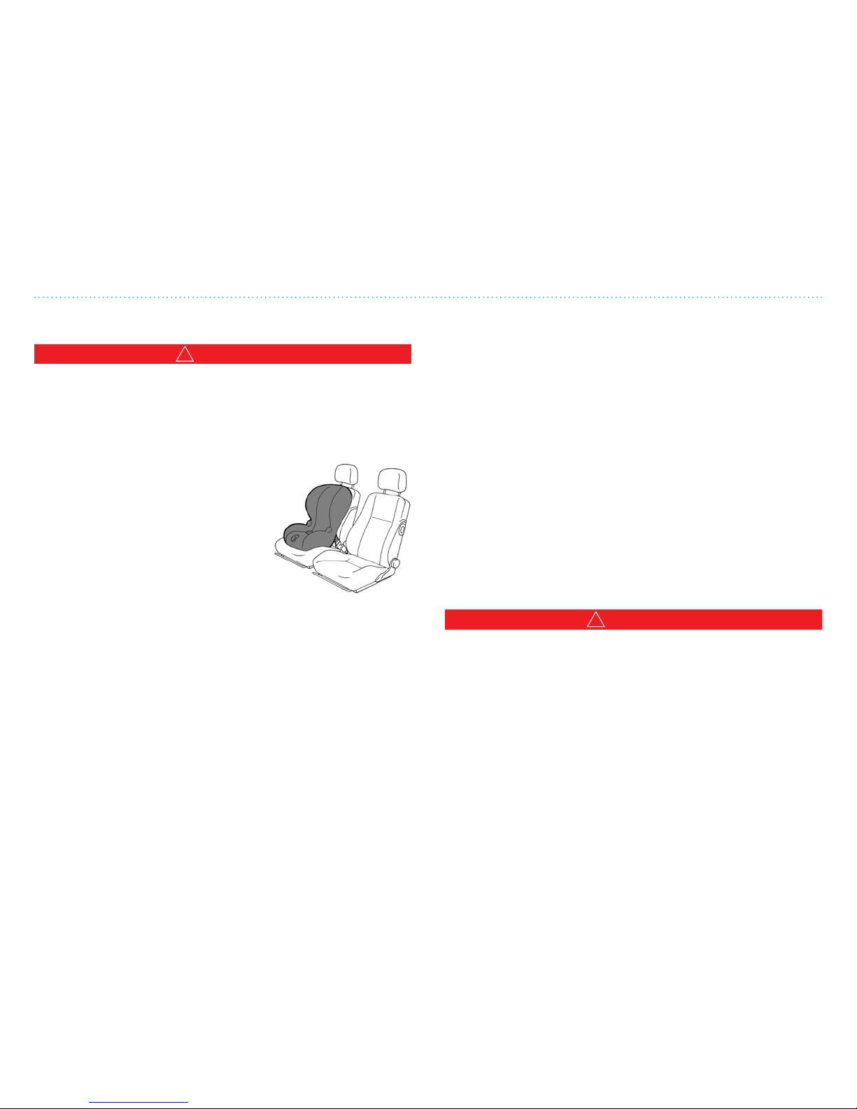
4. Driving and Safety
421
Child Seat Installation Using the Safety Belts
!
WARNING
The automatic locking retractor (ALR) in the front passenger
seat must be used when installing a child restraint using the
safety belt system. Failure to use the ALR mode will result in
the child restraint not being properly secured and cause injury
to a child in a sudden stop or collision.
Follow these steps to install a forwardfacing child restraint using the safety
belt system:
1. Move the seat to the rearmost
position.
2. Position the child restraint on the
seat. The back of the child restraint
should be secured against the
vehicle seat back.
3. Route the safety belt tongue through the child restraint and
insert it into the buckle until you hear and feel the latch
engage. Be sure to follow the child restraint manufacturer’s
instructions for belt routing.
4. If the child restraint is equipped with a top tether strap,
route the top tether strap and secure the tether strap to
the tether anchor point. The tether anchor point can be
found on the oor of the cargo compartment behind the
front passenger seat. Adjust the head restraints if needed.
Tighten the tether strap according to the manufacturer’s
instructions to remove any slack.
Children and Safety
5. Pull the shoulder belt until the belt is fully extended. At this
time, the seat belt retractor is in the ALR mode. It reverts to
normal sensitive mode when the seat belt is fully retracted.
See page 415 for more information.
6. Allow the safety belt to retract. Pull up on the shoulder belt
to remove any slack in the belt. Remove any additional
slack from the seat belt; press downward and rearward
rmly in the center of the child restraint with your knee
to compress the vehicle seat cushion and seat back while
pulling up on the safety belt.
7. Tighten the tether strap according to the manufacturer’s
instructions to remove any slack.
8. Check to make sure the child restraint is properly secured
prior to each use. If the child restraint is loose, repeat steps
above to ensure it is secured properly.
Installing Booster Seats
!
WARNING
• Make sure the shoulder portion of the belt is away from the
child’s face and neck and the lap portion of the belt does not
cross the stomach. Never place, or allow a child to place, the
shoulder belt under a child’s arm or behind the back because
it reduces the protection for the upper part of the body and
may increase the risk of injury or death in a collision.
• Choose only a child restraint or booster seat with a label
certifying that it complies with Federal Motor Vehicle Safety
Standard 213. Ensure that the child restraint or booster seat is
compatible with the vehicle’s seat and safety belt system.
Page 70
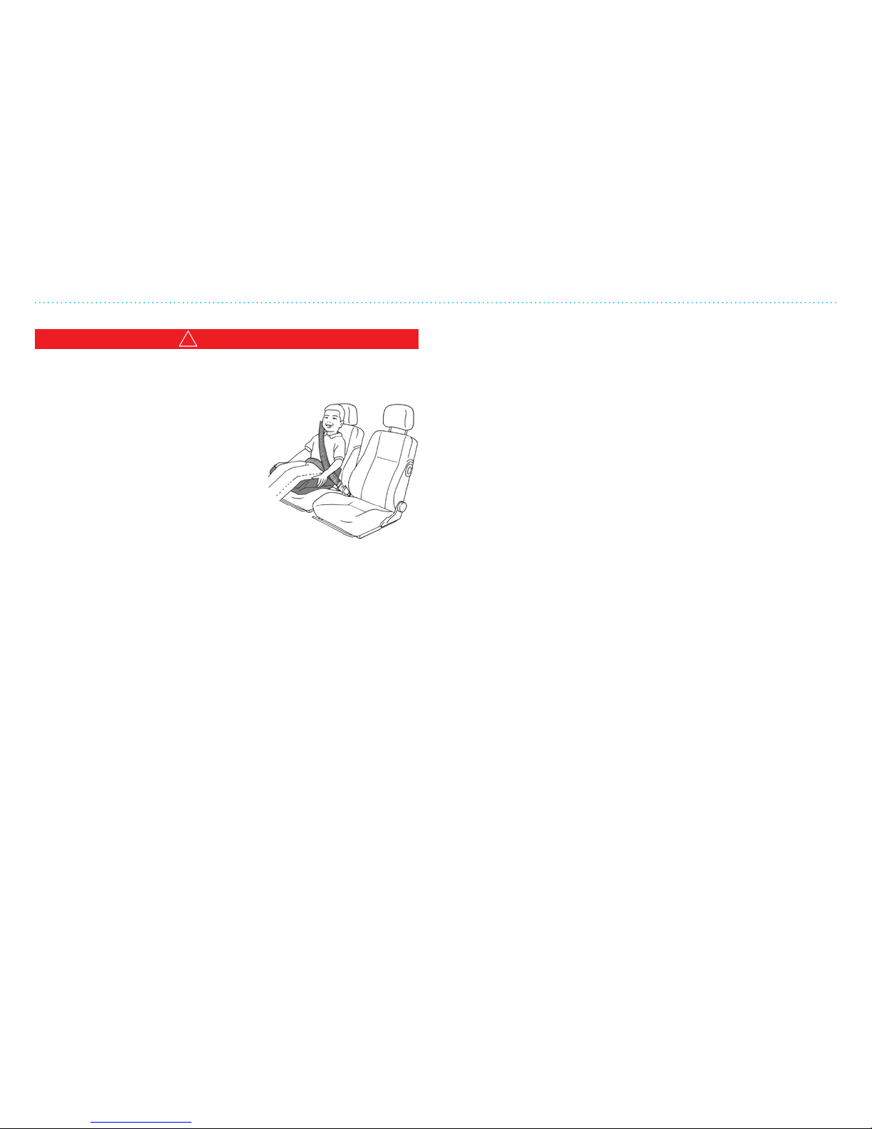
4. Driving and Safety
422
!
WARNING
The automatic locking retractor (ALR) mode should NOT be
used when using a booster seat with the safety belts.
Follow these steps to install a booster
seat:
1. Move the seat to the rearmost
position.
2. Position the booster seat on the
front passenger in a front-facing
direction. Always follow the
booster seat manufacturer’s
instructions.
3. Ensure that the seat is stable. If necessary, adjust the head
restraint.
4. Position the lap portion of the safety belt low and snug on
the child’s hips.
5. Pull the shoulder belt portion of the safety belt toward the
retractor to take up extra slack.
6. Ensure the shoulder belt is positioned across the top,
middle portion of the child’s shoulder.
7. Insert the tongue of the belt securely into the buckle.
Follow the warnings, cautions and instructions for properly
fastening a safety belt shown in the Safety Belts section on
page 415.
Children and Safety
Page 71
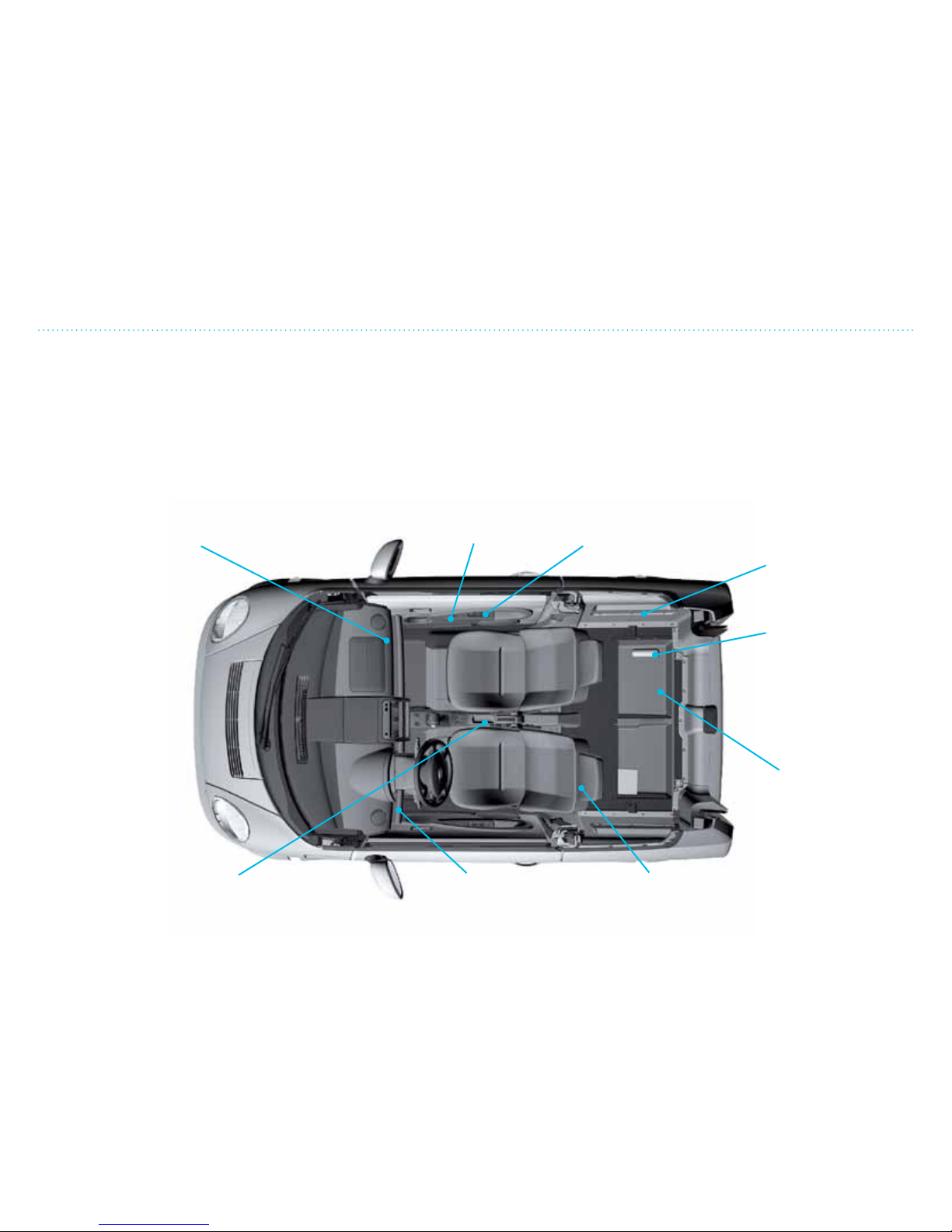
4. Driving and Safety
423
Luggage Compartment and Storage
Luggage Compartment and Storage
Loading and inadequate stowing/securing of cargo can
compromise the safety of the vehicle and its stability.
The cargo and its placement aect the driving performance
of the THINK City. Proper weight placement and a low
gravity point make for a stable vehicle and reduces the risk of
shtailing. Never exceed the weight limit stated on the label
inside the driver door jam.
Never let objects lie loose and unsecured in the vehicle. If a
sudden stop is made or if there is a collision, these objects can
y through the air and injure both driver and passenger. Always
place the heaviest objects on the oor and up against the seat
backs so they cannot move around. A bag weighing 40 lb will
equal a colliding weight of 2,000 lb in a 31 mph collision.
Shelf on the
dashboard
Shelf on
driver side
Pockets on back
side of seats
Storage area
under luggage
compartment
Tire changing tools
Space on the side of the
luggage compartment
Coin holder
Door side
pocket
Storage space
in center
console
Page 72
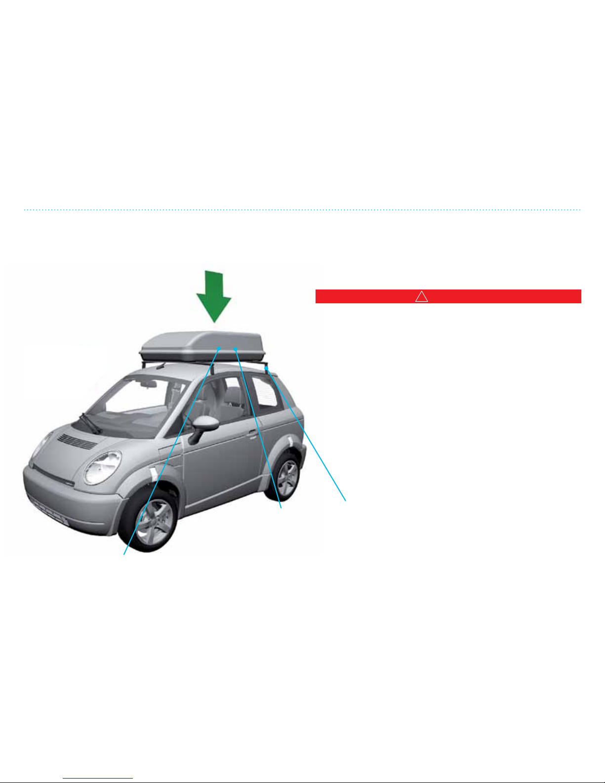
4. Driving and Safety
424
Break-ins and the
Remove all valuables that are visible when you leave the
vehicle. If the radio has a detachable front panel, take it out.
Avoiding Roll Over
!
WARNING
Safety belts help reduce the risk of injury in collisions and
rollovers. In a rollover crash, an unbelted or improperly belted
person is significantly more likely to be injured or killed than a
person properly wearing a safety belt.
Your Think City vehicle was designed to have a low center of
gravity reducing the chances of vehicle rollover. However, as
with any vehicle, loss of control could result in a collision with
other vehicles or objects and cause the vehicle to roll over,
particularly if the loss of control causes the vehicle to slide
sideways. Be attentive at all times, and avoid driving when
tired. Never drive when under the inuence of alcohol
or drugs (including prescription or over-the-counter
drugs which may cause drowsiness). Always wear
your safety belt as outlined in the Safety Belts
section of this manual,
and also instruct your
passengers to do so.
Driving with Roof Racks and Ski Box
Driving with Roof Racks and Ski Box
Roof racks will increase the vehicle’s wind resistance and
shorten the driving distance. Always remove the roof racks
when not needed.
Use only roof racks and ski box that are
designed for THINK City. Check with
your dealer. Maximum weight is 110 lb.
Cargo should not be placed directly on
the roof.
Place the heaviest objects on the bottom
of the ski box. This will help to lessen the
effect on driving performance.
Spread the cargo evenly
so the weight is divided
equally. Items inside the
box must also be secured
to avoid shifting.
Check that the roof racks
are properly mounted.
Follow the manufacturer’s
instructions carefully or
contact your dealer for
assistance.
Max
110 lb
Page 73
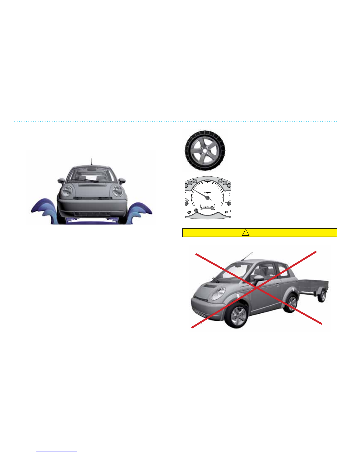
4. Driving and Safety
425
Driving in Water, Winter Conditions and Using Snow Chains
Driving in Water
To avoid hydroplaning, which can make steering of the vehicle
unstable, do not drive fast through deep water. Aer driving
through puddles, check your brakes – wet brakes are less
eective than when dry.
Driving on Snow and Ice
• Reduce your speed and allow for increased safe distances
when driving on snow and ice. Avoid fast acceleration, hard
braking and sharp turns as much as possible.
• Use good quality snow tires on all 4 wheels with sucient
tread, or studded tires as needed.
• Use the same type and size of snow tires on all 4 wheels;
do not mix dierent brands and tread.
• Studded tires should be “driven in” carefully the rst 300-
400 miles to assure the studs are worked well into the
rubber.
• The regenerative brakes and ABS brakes communicate such
that if the ABS brakes are applied, the regenerative braking
function disengages.
• Use of snow chains is only possible when using tires that are
165/65 R14 on steel rims (if equipped).
• Snow chains should only be used on
the front wheels; make sure that no
part of the chain sticks out or is loose
which could damage the brakes, shock
absorbers or other parts of the vehicle.
• Never drive faster than 30 mph with
snow chains.
• Do not drive with snow chains on bare
ground. This puts heavy wear on the
chains, tires and vehicle.
• Consult your dealer for advice on
purchasing snow chains for your
vehicle.
!
CAUTION
THINK City is not designed to pull a trailer or other vehicles.
mph
10
0
20
30
40
50
60
70
80
0
90
100
110
120
Page 74
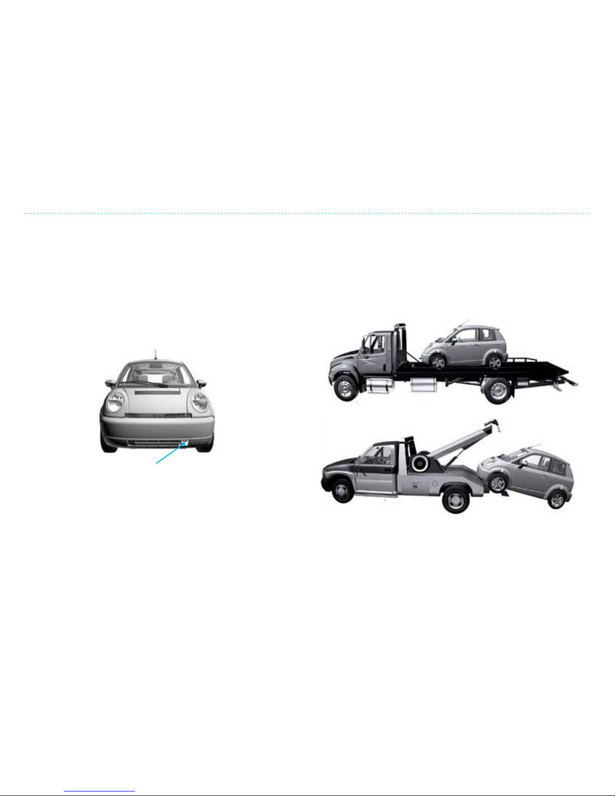
4. Driving and Safety
426
Towing
Towing hook in the front
Recommended towing options:
• Transporting the vehicle on a atbed.
• Towing on a ramp with front wheels raised.
• If rear wheels are raised, the front wheels must be on a dolly
to avoid damage to the transmission (front wheels must not
rotate).
Towing
Contact a towing company if you need to have your vehicle
towed. Perhaps you have an insurance or emergency road
service to contact.
When towing a THINK City:
• Gear selector in N (NEUTRAL) – turn the ignition key “OFF”.
Do not take the key out!
• Remember that the brakes need more force to work when
the power is o.
Page 75
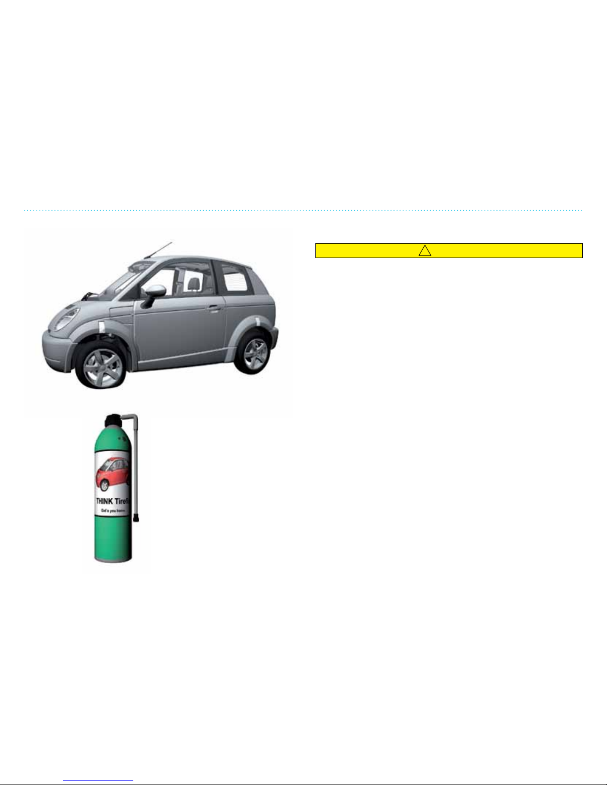
4. Driving and Safety
427
Wheels and Tires
Flat Tire
!
CAUTION
The tire repair kit is only a temporary fix. Change the tire or
have it repaired immediately at the vehicle or tire dealer.
• If you have a at tire, brake carefully and slow down – nd a
safe place away from trac at which to stop.
• Turn on the emergency hazard lights!
• Wear a reective safety vest!
• Put the emergency warning triangle on the road.
• THINK City does not have a spare tire and jack – it has a tire
repair kit in the luggage compartment where the warning
triangle is found. Read the directions.
• Do not use a tire repair kit from another vehicle.
When you are driving with a temporarily repaired tire,
remember:
• Never drive over 50 mph; stay at the lowest speed possible.
• Have as little extra weight in the vehicle as possible and
never more than the load limit stated on the tire label on the
driver side door jam.
• Drive only as far as you have to get a permanent repair.
• Do not drive with more than one temporarily repaired tire at
a time.
• Be sure to purchase a replacement repair kit at a
THINK NA dealer.
See tire manual for additional information.
Tire repair kit.
Read the instructions
on the canister.
Wheels and Tires
Page 76
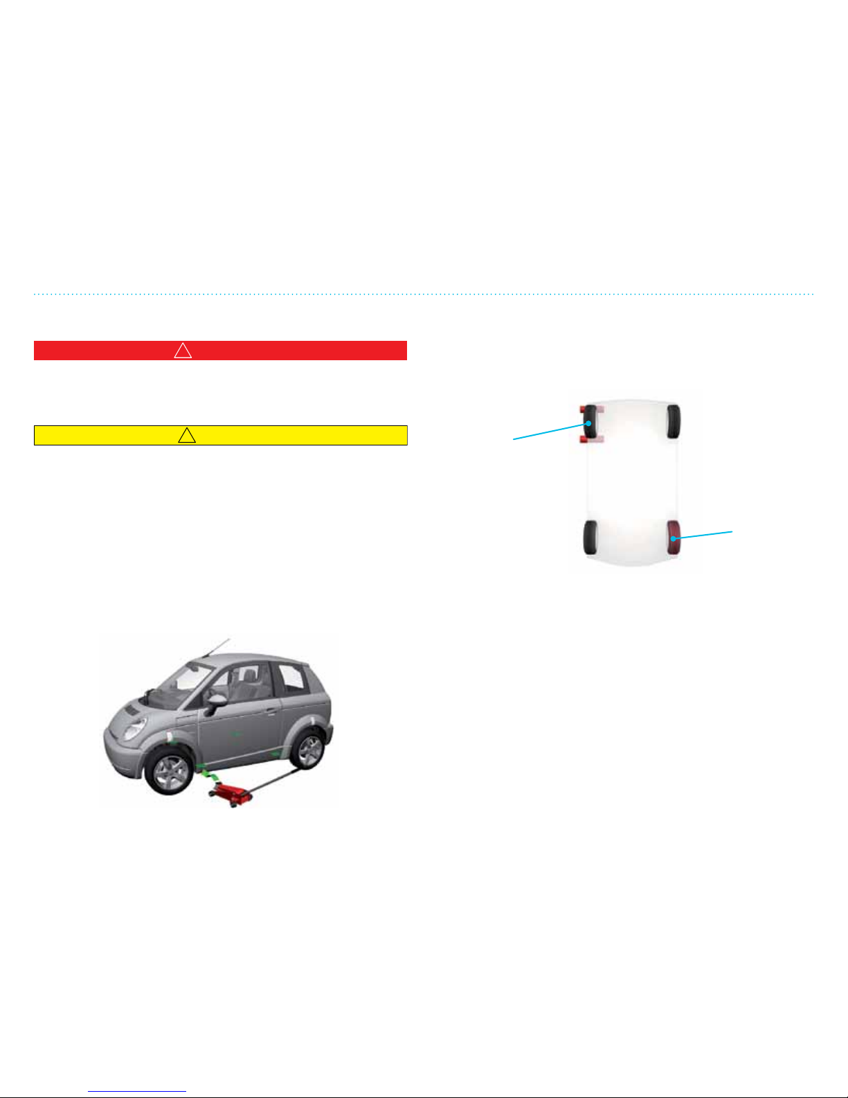
4. Driving and Safety
428
4. Put the gear selector in P, turn the ignition key to o “O”
and block the wheel that is diagonally across on the
opposite side of the vehicle in relation to the wheel you
are changing (see illustration).
Changing a Wheel
!
WARNING
Ensure that the jack is positioned such that it rests under the
structural components of the vehicle and not on the battery
compartment.
!
CAUTION
Do not start the motor while the vehicle is raised on the jack.
Stay clear of the under part of the vehicle when it is jacked up
(do not put arms, feet, legs under the vehicle).
You will need a jack (preferably a heavy-duty 1-ton jack) to
change a wheel.
Before the vehicle is jacked up, check the following:
1. Park on an even surface such as asphalt.
2. Pull up the parking brake.
3. If in a heavily congested trac area, put the warning
triangle out and turn on the emergency ashers.
Changing a Wheel
1. Remove the lug nut cover and hub cap/wheel cover.
2. Loosen all lug nuts a half turn (just loosen, do not unscrew).
3. Place the jack under the chassis jacking point. Jack it up
carefully and check that the chassis is being lied up.
4. Check that the jack is stable and that the jack is positioned
at the jacking point.
5. Jack up until the wheel clears the ground; make sure the
vehicle is still stable.
6. Unscrew the lug nuts and remove the wheel. Put the new
wheel on and tighten the lug nuts.
7. Tighten the lug nuts diagonally across from each other,
one pair at a time, so that the wheel sits tightly against the
mounting surface.
8. Let the vehicle down and tighten all the lug nuts. Remove
the wheel blocks.
Block this
wheel with
stones or
wooden
blocks, etc.
Wheel to be
changed
Page 77

4. Driving and Safety
429
Tire Pressure Monitoring System (TPMS)
Tire Pressure Monitoring System (TPMS)
Each tire, including the spare (if provided), should be checked
monthly when cold and inated to the ination pressure
recommended by the vehicle manufacturer on the vehicle
placard or tire ination pressure label on the driver side door
jamb. (If your vehicle has tires of a dierent size than the size
indicated on the vehicle placard or tire ination pressure
label, you should determine the proper tire
ination pressure for those tires.)
As an added safety feature, your vehicle
has been equipped with a tire pressure
monitoring system (TPMS) that illuminates
a low tire pressure telltale lamp when one
or more of your tires is signicantly underinated. Accordingly, when the low tire pressure telltale lamp
illuminates, you should stop and check your tires as soon as
possible, and inate them to the proper pressure.
Driving on a signicantly under-inated tire causes the tire
to overheat and can lead to tire failure. Under-ination also
reduces fuel eciency and tire tread life, and may aect the
vehicle’s handling and stopping ability.
Please note that the TPMS is not a substitute for proper tire
maintenance, and it is the driver’s responsibility to maintain
correct tire pressure, even if under-ination has not reached
the level to trigger illumination of the TPMS low tire pressure
telltale lamp.
Your vehicle has also been equipped with a TPMS malfunction
indicator to indicate when the system is not operating
properly. The TPMS malfunction indicator is combined with
the low tire pressure telltale lamp. When the system detects
a malfunction, the telltale lamp will ash for approximately
one minute and then remain continuously illuminated. This
sequence will continue upon subsequent vehicle start-ups
as long as the malfunction exists. When the malfunction
indicator is illuminated, the system may not be able to detect
or signal low tire pressure as intended. TPMS malfunctions
may occur for a variety of reasons, including the installation
of replacement or alternate tires or wheels on the vehicle that
prevent the TPMS from functioning properly. Always check the
TPMS malfunction telltale lamp aer replacing one or more
tires or wheels on your vehicle to ensure that the replacement
or alternate tires and wheels allow the TPMS to continue to
function properly.
TPMS Set
NOTE: Aer changing tires, it is necessary for the system to
re-learn the sensor ID´s in each wheel. THINK recommends
that this operation is performed aer conducting any work that
involves removing one or more wheels from the vehicle.
NOTE: Any wheel tted to the vehicle must be tted with the
correct sensor for the THINK TPMS. If uncertain, contact your
dealer for assistance.
Page 78
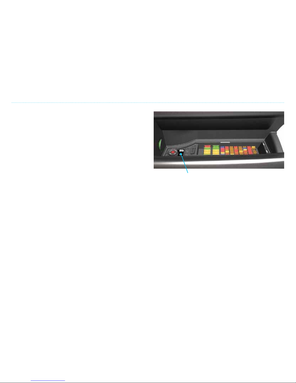
4. Driving and Safety
430
Tire Pressure Monitoring System (TPMS)
To set your TPMS:
1. Make sure that you have the correct pressure in all 4 tires.
The front tires should be inated to 36 psi (2.5 bar) and rear
tires inated to 43 psi (3.0 bar). Tire pressure should always
be checked on cold tires and with an accurate pressure gage.
Performing a TPMS Set sequence with incorrect tire pressures
may prevent the TPMS from functioning correctly and not
indicating low tire pressure or system malfunction.
2. Turn the ignition on and make sure that the vehicle is in “Run
mode” by checking that the green vehicle telltale lamp on the
center stack is illuminated.
3. Press the TPMS Set button for between 3 to 6 seconds, until
the TPMS telltale lamp starts ashing rapidly and a beep noise
is heard. If the vehicle is turned o before this sequence is
complete, the system will indicate a malfunction when the
vehicle is started up again and the TPMS telltale lamp will
ash for about 1 minute and then remain illuminated. If this
happens, start over from Step 2.
4. Drive the vehicle for up to 10 minutes above 15 mph (25 km/h)
until the TPMS telltale lamp stops ashing and a beep noise is
heard from the vehicle. If the speed is reduced below 15 mph
(25 km/h), the learn process will pause. The process will
resume when the speed is above 15 mph again. Increasing the
speed above 15 mph has no eect on the time the TPMS set
process will take.
5. When the TPMS telltale lamp has stopped ashing, the learn
process is complete and the system is fully operational.
TPMS set (under the
plastic panel)
Page 79
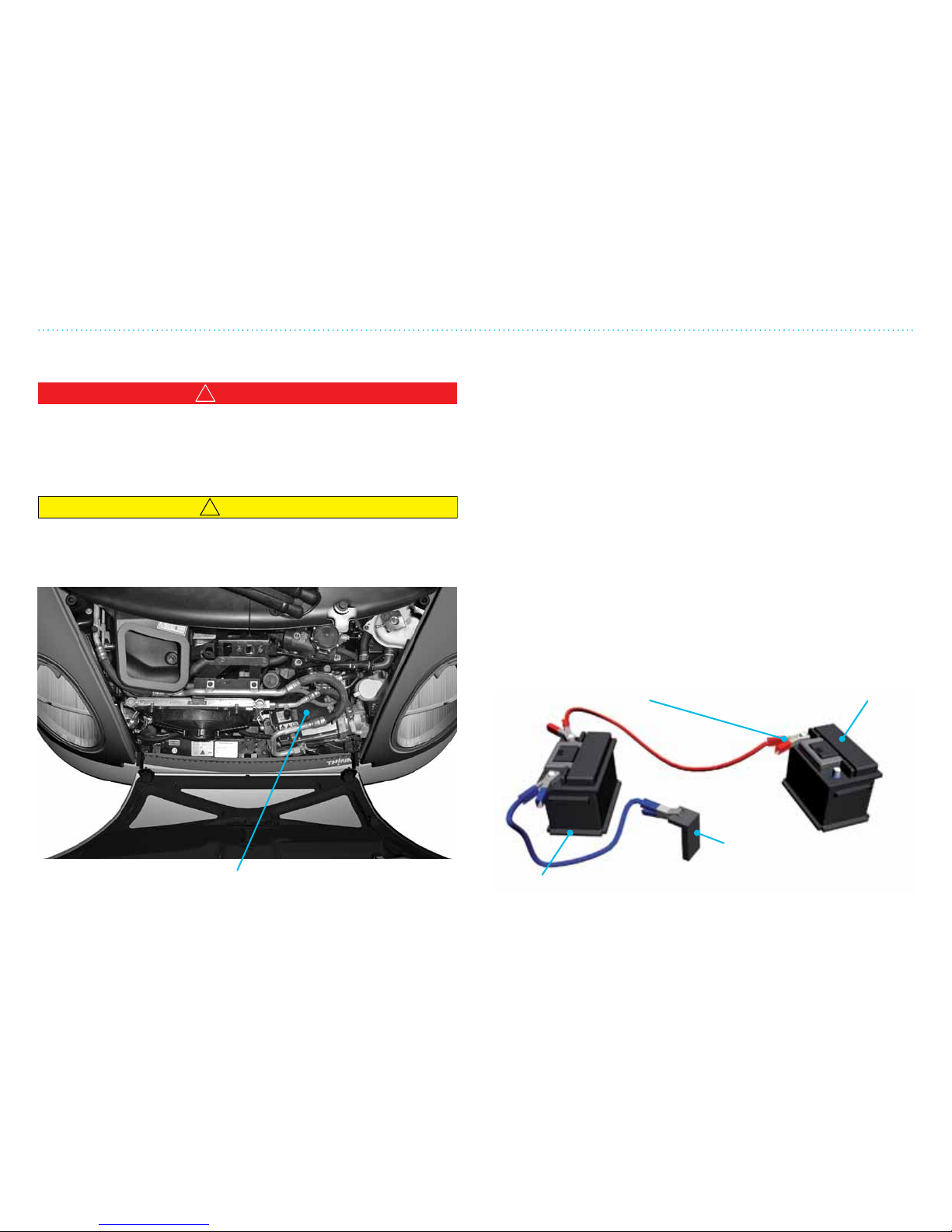
4. Driving and Safety
431
Jump Start
12V battery
The 12V auxiliary battery has much the same function as in
a regular vehicle; the battery can be depleted if the vehicle’s
lights are le on. The 12V auxiliary battery and the traction
battery are two separate units so that the auxiliary battery
can be dead while the traction battery is fully charged. At
the same time, it does not help to charge the 12V auxiliary
battery if the traction battery is completely discharged.
Prior to using the jumper cables:
• Be sure that the jumper cables are long enough to reach from
battery to battery.
• Check that the ventilation caps are secure.
• Put the assisting vehicle in NEUTRAL and engage the parking
brake.
• Turn o all electric features on THINK City and put the gear in
P (PARK), pull the handbrake and turn ignition key to o
“O”.
+
+
1. Connect the positive charge to the positive
connection on the THINK City battery.
2. Connect one end to the
negative charge and the
other to metal (ground)
away from the THINK City
battery.
12V THINK City
battery
12V assisting
vehicle
battery
Jump Start
!
WARNING
The 12V auxiliary battery contains sulfuric acid. If exposed,
rinse thoroughly with water and contact a doctor.
The battery has gaseous vapors which can explode when
ignited by flames, sparks or cigarettes.
!
CAUTION
Do not try to push-start your THINK City if the auxiliary
battery is depleted. An electric vehicle cannot be started this way.
–
Page 80

Page 81

In order for THINK City’s warranty to be valid, it is important
to follow the recommendations in this User Manual, and
that all service repairs are made at an authorized dealer or
workshop according to the specied mileage or intervals
listed in the Service and Warranty Manual.
If you experience problems with the vehicle, contact the
dealership immediately. We recommend the dealership for
all repairs. You are guaranteed original replacement parts
and that the repairs are made by trained mechanics. This
will ensure that your vehicle is maintained properly and
kept in good running condition.
5. Service and Maintenance
Page 82

5. Service and Maintenance
52
Page 83

5. Service and Maintenance
53
Table of Contents
General Maintenance ................................................................................................................................................. 54
Washing and Cleaning ............................................................................................................................................... 56
The Motor Compartment — Opening and Closing ......................................................................................... 58
Motor Coolant — Checking and Refilling ............................................................................................................59
Cooling System’s Safety System and Switches .............................................................................................. 510
Brake Fluid, Power Steering and Windshield Washer Fluid ................................................................... 511
12V Battery .................................................................................................................................................................... 512
Changing Light Bulbs in Front .............................................................................................................................. 513
Changing the Rear Light Bulbs ............................................................................................................................. 516
Fuses .................................................................................................................................................................................517
Changing the Windshield Wiper and Key Fob Battery ............................................................................. 519
Tires ................................................................................................................................................................................. 520
Tire Markings ............................................................................................................................................................... 521
Uniform Tire Quality Grading ..............................................................................................................................522
Vehicle Loading Information................................................................................................................................523
Page 84

5. Service and Maintenance
54
General Maintenance
General Maintenance
This section provides information on those service and
maintenance items you can do yourself and items your
dealer should take care of. What the dealer takes care of is also
described in the Service and Warranty Manual.
Maintenance that you can do yourself:
• General safety rules
• Clean the vehicle inside and out
• Clean the motor compartment and parts
• Rell windshield washer uid and motor coolant
• Check power steering uid
• Maintenance of the 12V battery
• Change light bulbs
• Change battery in the key fob
Page 85
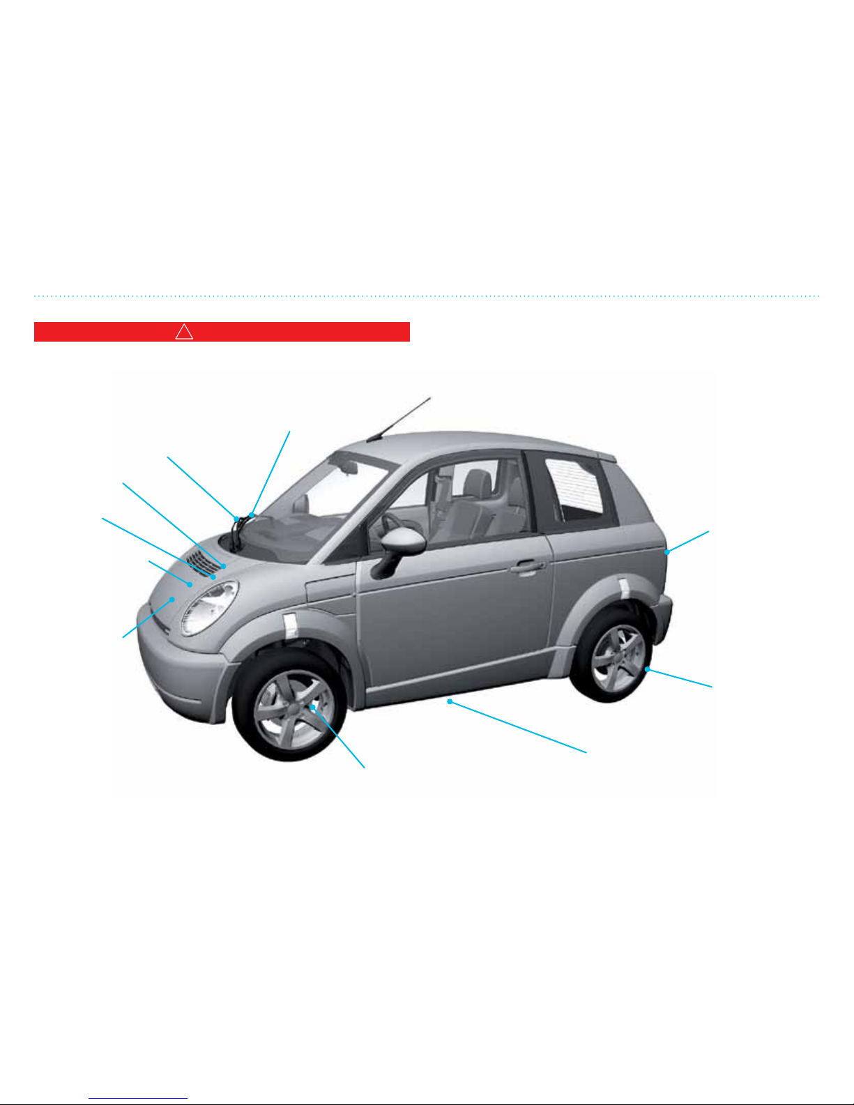
5. Service and Maintenance
55
General Maintenance
For every 600 miles/once a month, check the following and
rell if necessary (see pages 59, 511):
!
WARNING
Remember to turn off the motor before checking motor fluids/
parts. Let the motor and gears cool down before working on
them. Keep all open flames away from the vehicle.
Check for worn
wiper blade
Check flow of
washer spray
Windshield
washer fluid
Power
steering fluid
Visual inspection of
the brake discs
Air pressure/
tire tread
Traction
battery
Check that
the lights and
warning lamps
are working
Motor coolant
Brake fluid
Page 86
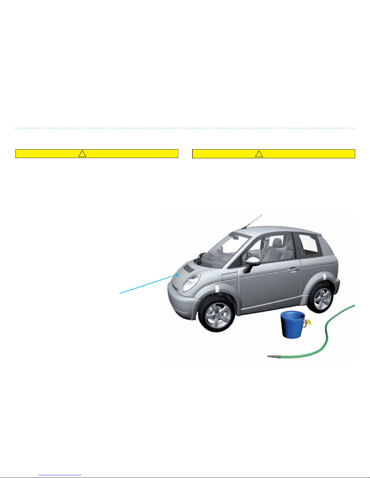
5. Service and Maintenance
56
Washing and Cleaning
THINK City has a dyed-throughout plastic
body. Wash with pH-neutral vehicle shampoo
in cool or lukewarm water. Rinse with clean
water and dry with a clean chamois or towel.
Do not wash the vehicle in direct sunlight
or when the body is hot as this can cause
discoloration. Regular vehicle cleaner can be
used on the THINK City. For resistant stains,
special degrease detergents for vehicles
can be used.
Washing in Car Washes
!
CAUTION
Do not use car washes that use acid in the detergent. Some car
washes, especially brushless ones, use some acid for cleaning.
The acid may react with some plastic vehicle components,
causing them to crack. This could affect their appearance, and
also could cause them to not function properly. Always check
with your car wash to confirm that acid is not used.
THINK City can be washed in commercial car washes. Remove
the antenna and luggage racks beforehand.
Washing and Cleaning
!
CAUTION
• Remove the charge cable before washing the vehicle.
• THINK City should not be polished! Wax and soaps with
abrasives can damage the surface.
• Do not use strong soap or household detergents and
solvents; this can cause discoloration.
General Guidelines for Washing/Cleaning
It is important to clean the vehicle regularly, especially in
winter climates. Bird droppings and insects can damage the
body if not removed immediately. Dirt and salt spray should
also be removed as quickly as possible to avoid damage.
Page 87
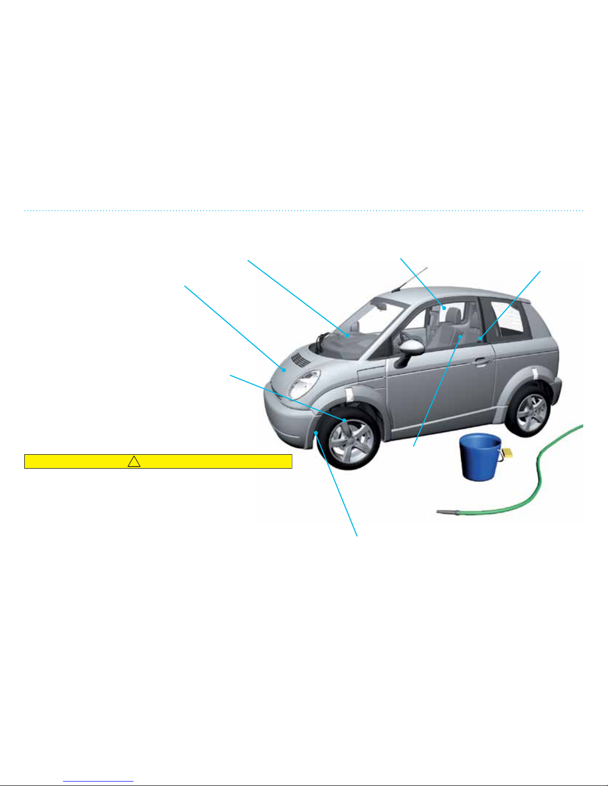
5. Service and Maintenance
57
!
CAUTION
To avoid staining or discoloring the wheels, follow the
recommendations below:
• Do not use a cleaner that uses strong acid or alkali contents
to clean the wheels.
• Do not apply wheel cleaners to the wheels when they are
hot. The wheel temperature should be the same as ambient
temperature.
• Rinse the wheel to completely remove the cleaner within 15
minutes aer the cleaner is applied.
Washing and Cleaning
Washing the Motor Compartment
Under normal operation, the motor
compartment does not require any
cleaning. However, if cleaning is
required, the vehicle must be turned
off and the charger cable must be
disconnected. Allow sufficient time
for the motor and gear box to cool
down before spraying with water.
Do not spray directly on electronic
connections and controls.
Washing the Wheels, Rims and Wheel Covers
Wash the wheels regularly with a sponge
dampened in a mild soap solution, especially
during winter months in areas where road salt is
used. If not removed, road salt can discolor the
wheels.
Washing the Underbody
Do not spray directly on the battery case. The
underside should be flushed during the regular
wash, especially under the fenders.
Wipe the instrument panel
with a damp cloth. Dry off
with a clean, dry cloth.
The safety belts
should be checked
regularly for worn or
damaged areas.
Use glass cleaner to wash the
windows. Windshield washer fluid
can also be used.
Interior Wash
Vacuum the seats
and carpeting.
Remove spots
with appropriate
cleaner.
Page 88
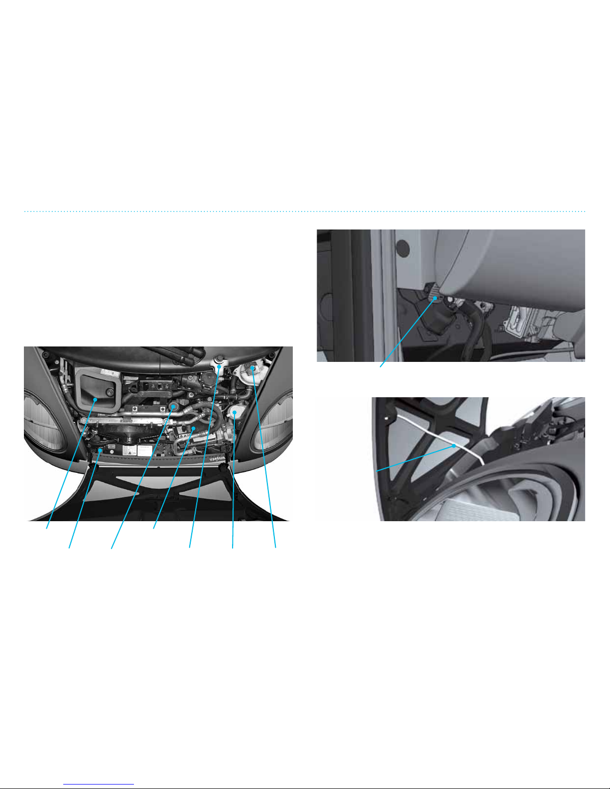
5. Service and Maintenance
58
The Motor Compartment — Opening/Closing
The Motor Compartment — Opening/Closing
The hood must be opened to check/rell motor coolant,
brake uid, power steering uid and windshield washer uid.
Turn o the motor and set the parking brake before opening
the hood. Pull the hood release handle under the instrument
panel. This will release the hood latch. Li the hood and
support it with the hood support strut.
Be sure the motor and gears are cool before touching any
areas of the motor.
Air intake
Handle to release the hood.
Inertia
sensor
12V
battery
Brake
fluid
Motor
coolant
Windshield
washer
fluid
Power
steering
fluid
Hood
support strut
To close the hood, put the hood support strut back into the
clamp, let the hood down and make sure it is locked (you
should hear a click when it is locked in place).
Page 89
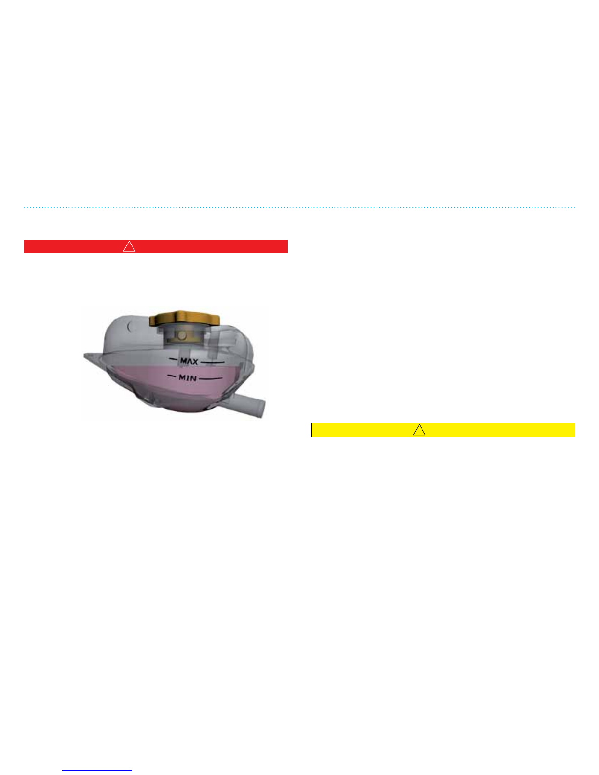
5. Service and Maintenance
59
Motor Coolant — Checking and Refilling
Motor Coolant — Checking and Refilling
!
WARNING
The cooling system is pressurized – do not remove the lid on
the radiator with the motor running or if the motor is hot.
Pressure in the cooling system can cause injury as steam/
scalding water can spray out when the lid is opened.
The level of the coolant can be read without removing the lid.
If the level is lower than the minimum range line, add more
coolant.
The coolant must be a 50/50 mixture of distilled water and
coolant. The level in the coolant reservoir should be measured
when the motor is cold. (A lesser concentrate of coolant and
pure water can be used, but contact your dealer immediately
for draining and relling with the correct concentration.)
A 50% concentration of coolant will protect the motor at
temperatures down to -34º F. It also prevents corrosion damage
to the motor and cooling system.
If the cooling system repeatedly needs lling, there may be a
problem; contact your dealer.
THINK City comes from the factory with prediluted All Vehicle
50/50 antifreeze/coolant from Prime®. Rell with the same
brand.
To rell the coolant:
1. Turn o the motor and let it cool down.
2. Place a piece of thick cloth over the coolant reservoir cap
and turn carefully counterclockwise (le). Carefully release
the steam and pressure before opening all the way.
3. When the pressure is fully released, unscrew the cap using
the cloth since steam and heat can still spray out.
4. Fill the reservoir slowly with the correct mixture (50/50) up
to the MAX line.
5. Screw the lid tight to prevent uid leaking out.
If you are uncertain if the coolant mixture is the right
concentration, it can be measured with a coolant gauge; contact
your dealer.
!
CAUTION
THINK City is not designed for temperatures under -13ºF.
See also Chapter 6 ”Specifications and Technical Data”.
Coolant
reservoir
Page 90
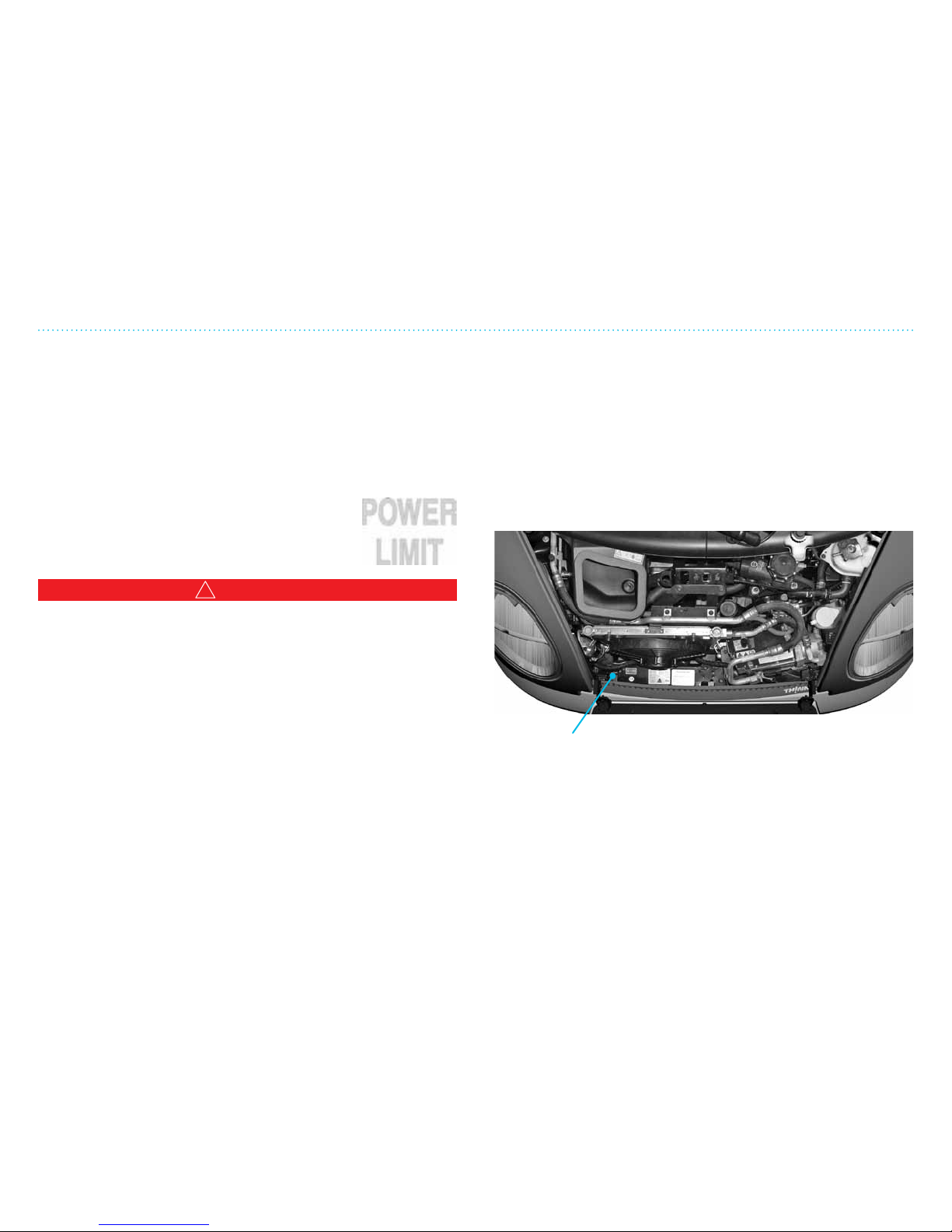
5. Service and Maintenance
510
Cooling System’s Safety System and Switches
Cooling System’s Safety System and Switches
Safety Mode For the Cooling System
The cooling system ensures the correct running temperature
for vital components (motor and drive controller). If there is
too little coolant in the system, or the system overheats due
to other factors, the safety mode will be activated to prevent
damage to the components.
Should this happen, the “POWER LIMIT”
warning will illuminate. The vehicle can still be
driven but will have limited power.
!
WARNING
If the vehicle is driven when overheated, the temperature can
increase even more and cause the drive system to turn itself
off. This means that steering and braking will be much heavier
and harder to use.
Stop the vehicle and turn o the motor. Check the coolant level
in the cooling system, rell if necessary. If the level is OK, let the
vehicle cool down and then start up. If it overheats again, take it
to your dealer to be checked.
Inertia Sensor
THINK City has an inertia sensor in the motor compartment.
This will cut the power to the traction battery in a collision, or a
powerful mechanical shock resulting from running into a curb
or similar object.
If the inertia sensor has been activated:
If the vehicle is not too damaged and can be driven safely, the
inertia sensor can be re-set by pushing the red button.
Inertia sensor
Page 91
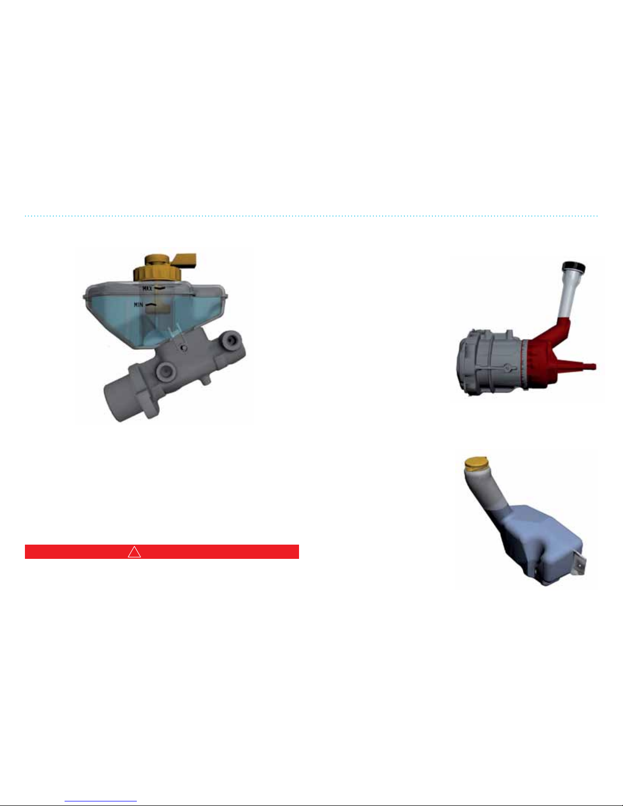
5. Service and Maintenance
511
Brake Fluid, Power Steering and Windshield Washer Fluid
Brake fluid
reservoir
Power steering
fluid reservoir
Windshield washer
fluid reservoir
Checking and Refilling the Brake Fluid
If the brake uid level is low, ll with brake uid type DOT 4 to
the MAX line (do not ll over this level).
To rell:
1. Clean the lid and surrounding area.
2. Check that water/pollutants do not get into the reservoir.
3. Rell with the recommended brake uid to the MAX level.
4. Screw the cap tightly and wipe the area clean.
!
WARNING
Note! Brake fluid is toxic!
Use only brake fluid type DOT 4. Use only brake fluid from an
unopened and sealed container/bottle.
Checking and Refilling the Power Steering Fluid
Check the power steering uid level regularly. Refer
to the Service and Warranty Manual for information
regarding recommended service intervals.
Refilling Windshield Washer Fluid
Rell as needed. Use pre-blended washer uid that withstands
freezing temperatures. In extremely cold climates/conditions,
do not ll the reservoir to the top.
Brake Fluid, Power Steering and Windshield Washer Fluid
Page 92
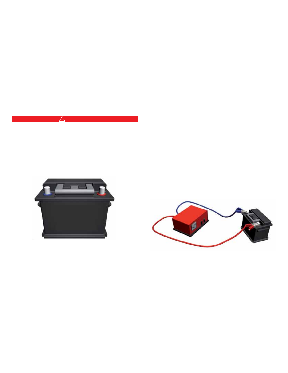
5. Service and Maintenance
512
12V Battery
12V Battery
!
WARNING
• A 12V battery contains sulfuric acid so be sure to protect
skin, eyes and clothes.
• If battery acid comes in contact with your skin or eyes, flush
immediately with water for at least 15 minutes and seek
medical attention.
• The battery can produce flammable gases. Do not allow
flames or sparks to come near the battery and make sure
there is sufficient ventilation.
THINK City comes with a maintenance-free 12V battery.
A few simple guidelines will help increase the battery’s lifetime.
• Keep the top of the battery clean; wipe with a dry cloth.
• Make sure the battery cables are fastened securely to the
battery terminals.
Remember that the vehicle uses power even when not in use so
it will gradually lose charge. Aer 30 days without being driven,
the battery will have a capacity of approximately 20%.
Leakage from the battery will damage the vehicle’s surface.
Rinse well with water and wipe clean.
Take used batteries to an approved recycling center or battery
sales store. Contact local authorities for more information.
Battery terminals, posts and related accessories contain lead;
wash hands aer handling the battery.
NOTE: The battery can be charged with an external battery
charger.
Charging the Battery
Must be done in a well-vented area. See the Battery Manual.
1. Connect to +
2. Connect to –
3. Turn on the charger
12V charger
Page 93
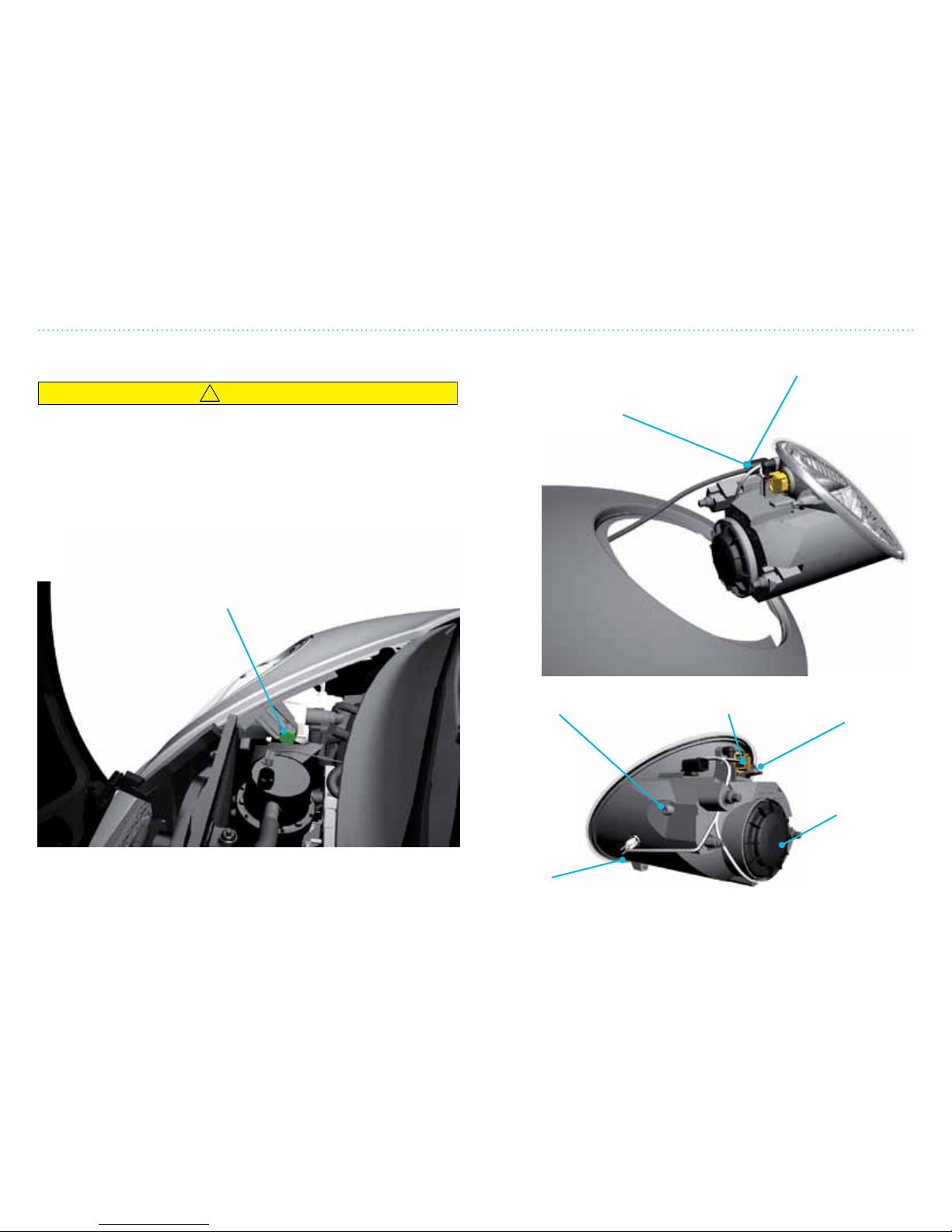
5. Service and Maintenance
513
Changing Light Bulbs in Front
Connection point for head lamps
Remove the plug
to release the
main lamp
Parking
lights
Screw for head lamps Turn signal
Plug for
electric
socket
Cover for
head lamps
Changing Light Bulbs in Front Head Lamp
!
CAUTION
• Do not remove bulbs if they are not going to be replaced
immediately. Lamp assemblies without bulbs can allow dirt
to build up on the reflectors and reduce brightness.
• Bulb and bulb sockets can be very hot. Allow the lamp to
cool down before changing a bulb. Otherwise you could be
burned if you touch them.
• Keep bulbs out of the reach of children. Wear eye and hand
protection.
To change a bulb in the main head lamp, you must unplug it
from the motor compartment. Unscrew the fastener screw and
pull the lamp outward.
Head lamp fastener screw
passenger side
Page 94
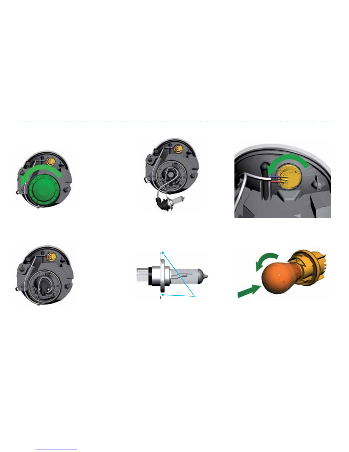
5. Service and Maintenance
514
Changing Light Bulbs in Front
Changing the Main Head Lamps Bulb (Halogen) Changing Turn Signal Bulb
1. Unscrew the cover for the
head lamp.
3. Turn the bulb holder slightly counterclockwise and pull out the complete bulb
holder. Take out the main bulb from the
holder and insert the new one. Remember
not to touch the new halogen bulb, use
gloves or a clean cloth.
1. To loosen the turn signal holder, turn
counterclockwise and take out the
holder and bulb.
2. Disconnect the electrical
connector from the bulb.
4. Make sure the guide pins are fed into the
holder correctly. Replace the bulb holder in
the head lamp in reverse order. Remember
to screw the cover back on. Note that the
wires to the lamp are on the inside of the
rubber gasket.
2. Twist the bulb counterclockwise while
pushing in slightly and pull straight out;
replace the bulb and install in reverse
order.
Page 95
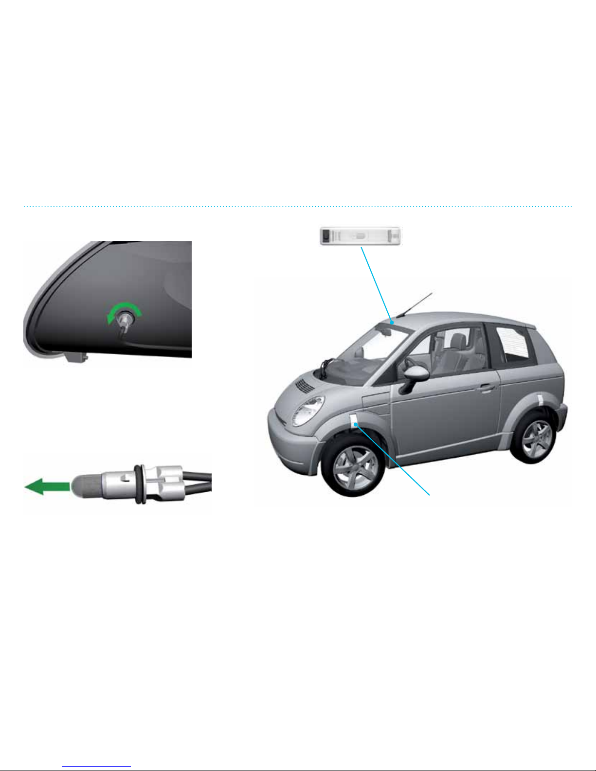
5. Service and Maintenance
515
Changing Light Bulbs in Front
Changing the Parking Light Bulb
1. To loosen the parking lights holder, twist
counterclockwise and pull out the holder
and bulb.
2. Pull out the bulb, insert a new one and
insert it back into the main head lamp.
Changing the Dome Light Bulb
Turn the dome light off (with switch in
center/off position). Pry out the bulb
using a flat screwdriver at the side
opposite the switch. Change the bulb
and press the light back into place.
Turn signal on front fender.
(LED lamp must be changed
by your dealer.)
Page 96
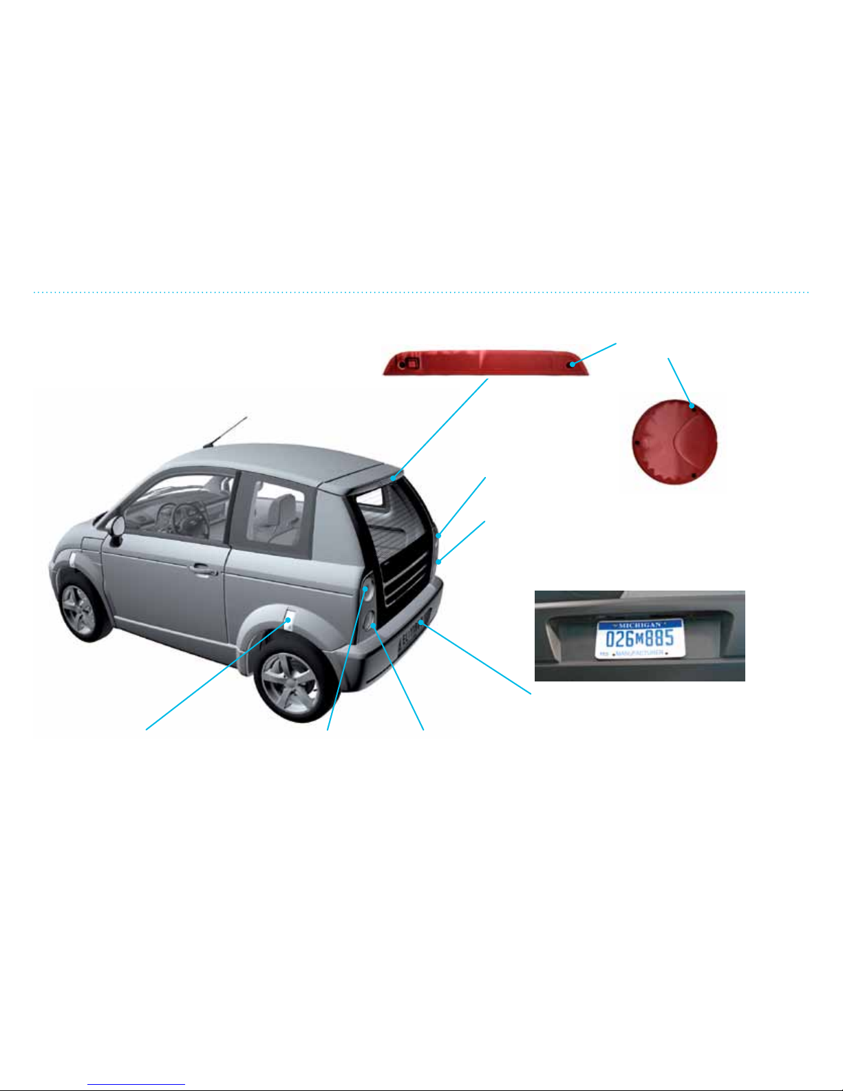
5. Service and Maintenance
516
Changing the Rear Light Bulbs
Rear reflector
(no bulb)
Turn signal/
reverse lamp
Brake light/
tail light/
reflector
License plate light
Use a small, flat screwdriver to pry open the
cover. Push in on lock on right side. Loosen the
bulb by turning a half turn counterclockwise.
Insert new bulb in reverse order.
Take out the bad bulb, insert
a new one (check that it
works) and screw the cover
back in place.
Loosen screws to
access the bulbs
High-mounted
brake light
Turn signal/
reverse lamp
Brake light/
tail light/reflector
Changing the Rear Light Bulbs
Page 97
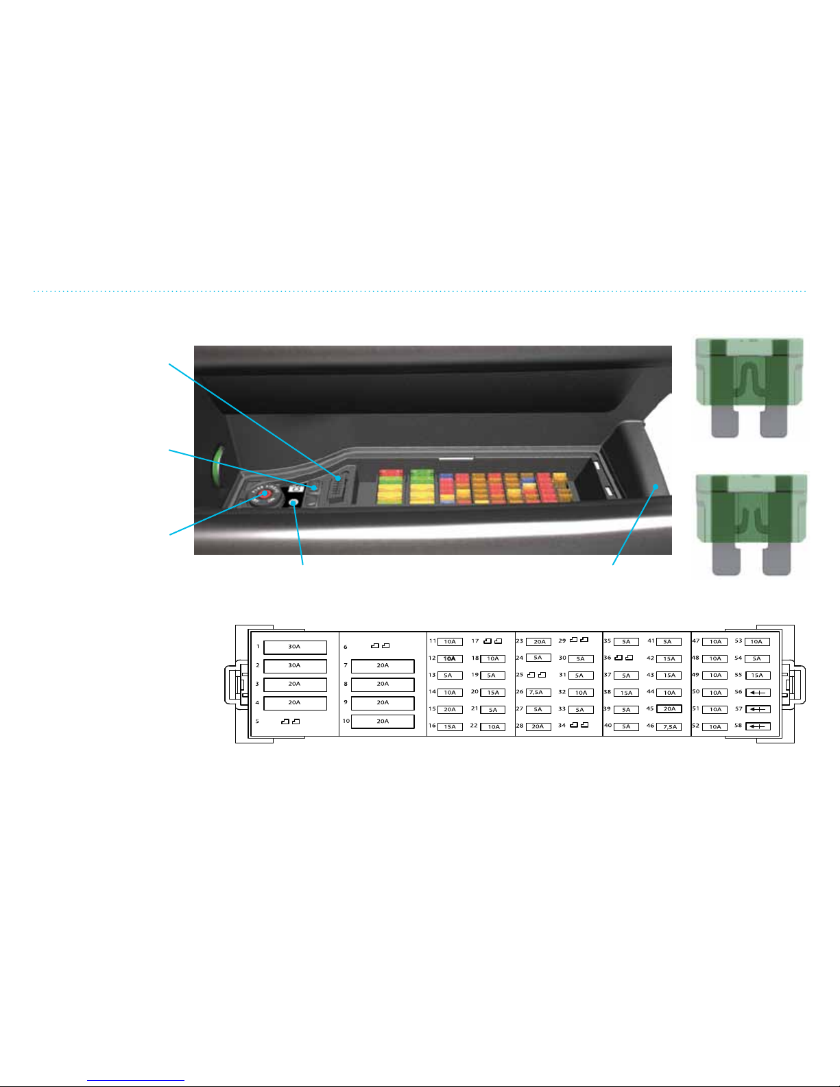
5. Service and Maintenance
517
Fuses
Diagnostics plug
(for service
department only).
Battery reset
(not applicable)
Disengaging the
passenger side air bag
(use the ignition key).
If one of the electrical
components in the vehicle
does not work, it may be
a blown fuse. Fuses must
be replaced with the same
amperage. Using the wrong
fuse can cause damage. If
a fuse blows repeatedly, it
means there is a problem in
the electrical components
and your dealer must check
the system.
Plastic cover
(lift to access
fuses)
TPMS set
Fuse blown
Fuse intact
Overview of fuses with reference to the list on page 5-18.
Fuses
Page 98

5. Service and Maintenance
518
Fuses
No. Fuse type Amp Component
1 Maxi 30 Main fuse to motor switch
2 Maxi 30 ABS pump motor
3 Maxi 20 ABS valve control
4 Maxi 20 Rear defroster
5 Not in use (reserve)
6 Not in use (reserve)
7 Maxi 20 Interior fan 25A with A/C (extra)
8 Maxi 20
Windshield wiper motor setting 1 and washer pump
9 Maxi 20 Electric windows
10 Maxi 20 A/C condensation fan (extra)
11 Mini 10 Brake light switch (pedal switch)
12 Mini 10 Vacuum pump for power brake
13 Mini 10 Water pump in cooling system
14 Mini 10 License plate light, parking light, rear daytime
driving lamps, lights on alarm
15 Mini 20 Power door locks (GEM)
16 Mini 15 Turn signal (GEM)
17 Not in use (reserve)
18 Mini 10 BMS unit
19 Mini 5 Diagnostics contact, climate control (CDCM)
20 Mini 15 Radio pin A4
21 Mini 5 VCU
22 Mini 10
Safety restraint system (air bag control module)
23 Mini 20 Radiator fan 2
24 Mini 5 Electric heated mirrors
25 Not in use (reserve)
26 Mini 7.5 Not in use (reserve)
27 Mini 5 Water pump, heating passenger comp.
28 Mini 20 Radiator fan 1
29 Not in use (reserve)
30 Mini 5 Brake pedal signal, gear selector-release
31 Mini 5 Radio pin A7
32 Mini 10 Rear fog lamp switch (if equipped)
No. Fuse type Amp Component
33 Mini 5 Electric mirror control current/BMS start
34 Not in use (reserve)
35 Mini 5 Ignition in Drive: PCU, VCU, drive relay Rly6
36 Not in use (reserve)
37 Mini 5 ABS start, interior fan relay and climate control unit
(CDCM) start
38 Mini 15 12V outlet passenger compartment
39 Mini 5 Ignition in Drive: indicator lamps, instrument
cluster
40 Mini 5 Ignition start signal to PCU
41 Mini 5 Interior lights (via relay Rly 17)
42 Mini 15 Horn (via relay Rly 18)
43 Mini 20 Windshield wiper motor setting 2, interval wiping
relay R15
44 Mini 10 Rear backing lights (via relay Rly 22)
45 Mini 20 Front windshield defroster setting 1 (extra)
46 Mini 7.5 Safety circuit for traction power, G-torque limit switch
47 Mini 10 Parking lights, right side (front and back)
48 Mini 10 Parking lights le side (front and back)
49 Mini 10 High beams, right side
50 Mini 10 High beams, le side
51 Mini 10 Low beams, right side
52 Mini 10 Low beams, le side
53 Mini 10 +12V connection point for mounted extra on
dashboard
54 Mini 5 Power steering (steering wheel sensor and power
steering pump)
55 Mini 15 Sunroof (extra)
Di56 Mini diode Code diode for radio control (not “power o” at
ignition key start) Direction is important!
Di57 Mini diode Code diode for front daytime driving lamps.
Direction is important!
Di58 Mini diode Code diode for Bi-halogen. Direction is important!
Page 99
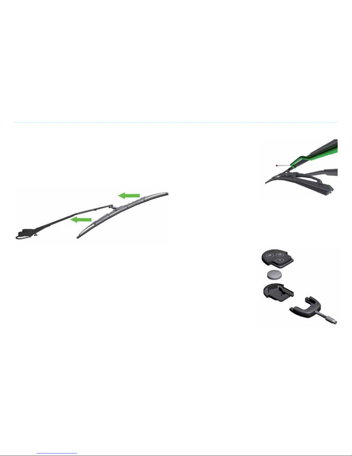
5. Service and Maintenance
519
Changing the Windshield Wiper and Key Fob Battery
Checking and Changing the Windshield Wiper
If the wiper does not clean properly, try washing the wiper
blade and windshield with washer uid and rinse with clear
water. If this does not help, the wiper may be worn and must be
replaced.
The wiper can be bought at service stations, auto parts stores
and from your THINK NA dealer.
NOTE: The wiper can only be lied slightly up from the
windshield – do not try to bend it out further.
Pull the wiper blade and arm up and away from the glass.
Remove the blade and install a new blade (refer to instructions
on the package).
Test the wiper before driving.
Adjusting the Wiper Spray Duct
The washer spray duct is located
on the wiper arm. This can be
adjusted with a needle – stick it
into the spray duct and turn to
the desired angle. Test that the
spray squirts the windshield at
the correct spot, remembering
that the speed of the vehicle will
aect the spray.
Changing the Battery in the Key Fob
1. Use a small screwdriver to separate the remote control
from the actual key.
2. The remote control can be opened up by pressing the
locking arms carefully away (one on each side).
3. Place the positive (+) side
of the battery in the same
direction (see diagram
on inside of remote
control).
4. Put the transmitter
together again. It is not
necessary to reprogram
the transmitter aer
changing the battery, it
should work as before.
+
—
Page 100
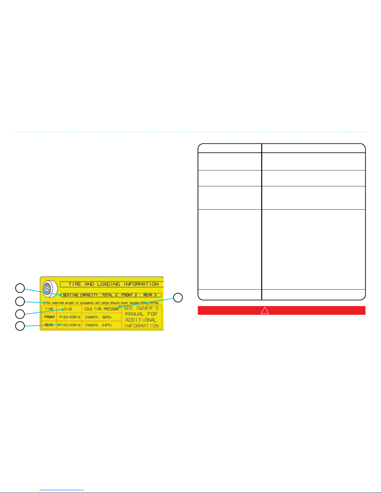
5. Service and Maintenance
520
Tires
ITEM DESCRIPTION
1. Seating capacity The maximum number of occupants
that can be seated in the vehicle.
2. Vehicle load limit See “Vehicle Loading Information” in
this section.
3. Original tire size The size of the tires originally
installed on the vehicle at the
factory.
4. Cold tire pressure Inflate the tires to this pressure
when the tires are cold. Tires are
considered COLD after the vehicle
has been parked for 3 or more
hours, or driven less than 1 mile
(1.6 km) at moderate speeds. The
recommended cold tire inflation is
set by the manufacturer to provide
the best balance of tire wear,
vehicle handling, drivability, tire
noise, etc., up to the vehicle’s gross
vehicle weight rating (GVWR).
5. Tire size Refer to “Tire Marking” section.
Tires
General Information
THINK City comes with tires designed for low road resistance
in order to maximize the driving distance. If you change the
tires, be sure new ones have the same specications. Check that
the tires have the legally required tread depth — too little tread
increases the chances of hydroplaning under wet conditions.
See also specications and technical information as well as the
purchase contract regarding wheels and tires. Be sure that all
four tires are the same type and dimension and have the same
rating for speed and load. If these precautions are not followed,
it can aect/reduce the car’s performance, the speedometer’s
accuracy, safety and braking capacity.
Tire Placard/ Label
The tire information label is located on the on the pillar behind
the driver’s door.
1
2
3
5
4
!
WARNING
Under-inflated tires can cause tire failure and increase the
risk of loss of vehicle control and possible injury or death
in the event of a collision. Refer to the tire manual for more
information on how to measure tire inflation pressure and
instructions on proper tire maintenance.
 Loading...