

Page 1
EHB/C Manual TH211118ER1 THINICON
1 Introduction:
EHB/EHC water-jacket heater is consists of heating element and temperature switches, is suitable
for all water-cooled engines. After installed heater, the engine starting ability will upgrade, reducing
startup losses, reduce wear and save fuel. Feature:
l Computer thermostatic control
l Set any temperature at the scene
l Digital display temperature and LED indicator shows the working status
l The operation panel to open/stop heating
l Precision die-cast aluminum water jacket case.
l Additional rubber sleeve to reduce thermal losses
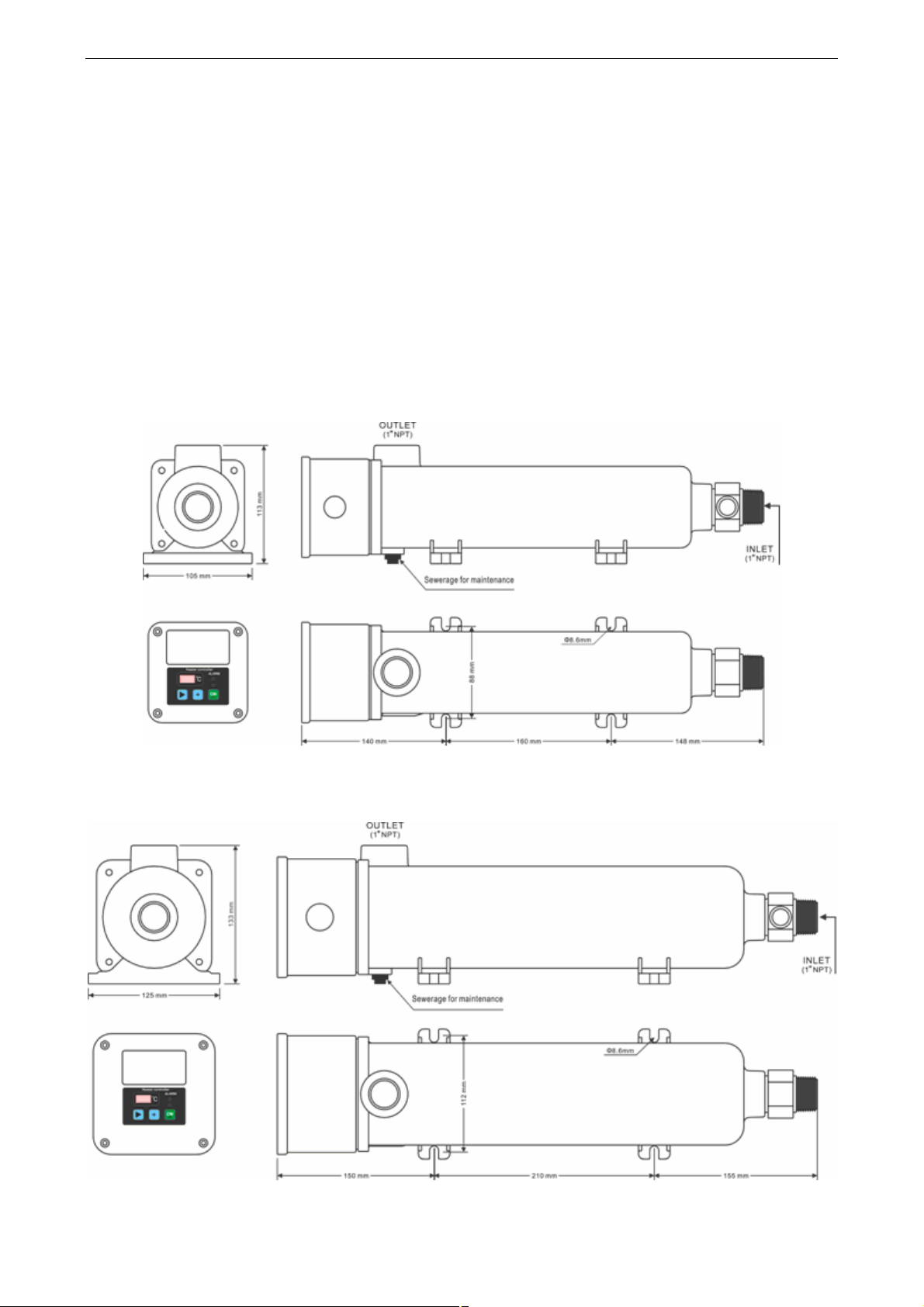
2 Shape and installation dimensions:
EHB
EHC
1
Page 2

EHB/C Manual TH211118ER1 THINICON
3 Wiring and electrical schematics:
4 Installation
Installed correctly is very important for the normal work of the heater, otherwise it will damage the
heater.
Position:
l Mounting feet horizontal installation.
l Isolation the engine vibration.
l The heater water-jacket is setting in low position as far as possible below the engine cooling fluid.
Electrical connections:
l Refer to the above wiring diagram.
l Must provide the good ground to ensure that the heater effectively grounding protection.
l User according to the power of the heater, select the appropriate main power circuit breaker to
ensure the effective heater overcurrent protection.
Warning:
l Heater installation and maintenance must be disconnected from the main
power supply.
l Must be installed and maintained by qualified engineers.
l During transport and parking, if the ambient temperature causes the
coolant in the heater water jacket to solidify, the maintenance drain must
be drained prior to use.
2
Page 3
EHB/C Manual TH211118ER1 THINICON
5 Specifications:
Model
Voltage
Power
Current
Suitable coolant volume
Insulation resistance
Voltage strength
Pressure test
Protection level
Operating temperature range
Storage temperature range
EHB1020 EHB1025 EHC1030 EHC1040 EHC1050
240V(1P2W)
2000W 2500W 3000W 4000W 5000W
8.3 10.4A 12.5A 16.7A 20.8A
10L 13L 16.5L 20.5L 25L
10MΩ
1800V
≥0.5Mpa
IP65
-20 to 70℃
-30 to 80℃
6 Operating instructions
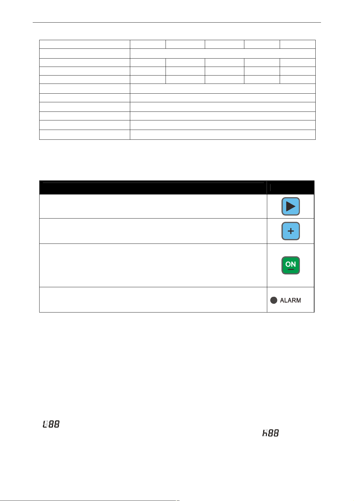
Operating buttons and LED
Functional Description
Setting
Continuous press this button 2 seconds to enter / exit parameter setting menu.
Name
Value Increase
When in parameters setting mode, this button is used to increase value.
START / LED
When the preheater switch on power, press the start button,the indicate lights is
on, the preheater into the automatic heating and protection of the work process.
Cycled state is holding.
When in parameters setting mode, this button is used to decrease value.
Alarm (FAILURE) LED
When the preheater is detected any one of the pump failure, sensor failure,
high temperature failure, the indicator light flashes.
Protective function:
Sensor failure: If detected the sensors open or short circuit, after delay confirmation, fault
indicator flashing, heating pipe work power relay disconnect, the digital display fault Code: A-02.
Temperature fault: Any time the controller detects that the temperature sensor reaches 95 ℃,
fault indicator flashing, heating pipe work power relay disconnect, digital display fault code: A-03.
Failure is not locked until the temperature is below the low limit temperature, the fault indicator is off,
continue to automatic control process。
Setting parameters:(Please enter the password first)
Low limit temperature:Used to setting the temperature setting limits for starting heating.
High limit temperature:Used to set setting stop heating limit temperature.
(Factory default heating temperature control range is 38 ℃ to 49 ℃)
3
Page 4
EHB/C Manual TH211118ER1 THINICON
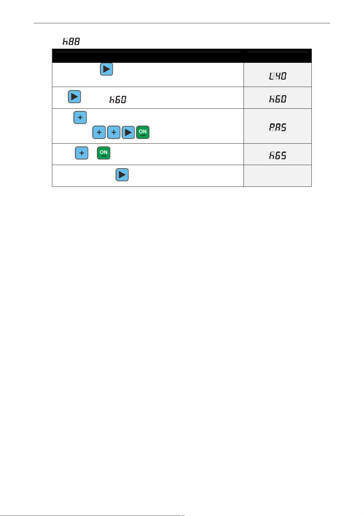
Setting:
Example high limit temperature is 65 ℃
Operation Description
Press and hold 2 seconds to enter into the parameter
setting menu, then displays the low temperature limit:
Tap scrolls to high limit temperature:
Press modify then PASS prompted for a password:
enter 2213( )
Press or can modify the parameters, then displays:
Then press and hold confirm and exit the modification
4
 Loading...