

Page 1
THIE S EN
E L E C
TRONICS
G M B H
E B2R
Mounting instruction for Electonic Rotating Beacon (ERB2)
Electronic Rotating Beacon for ultra-light aircraft
Dear customer,
the Electronic Rotating Beacon 2 (ERB2) is a highly innovative product which contributes to saver airspace.
The new LED technology allows an incredibly excellent, red light with only approx. 10% of the input power compared with
conventional lights. The casting in a high-optical plastic makes the ERB absolutely insensitive against water, vibrations and other
environmental influence. The efficiency of the output is much higher, than with conventional electric light bulbs. The self-warming
of the ERB is low and can be determined as safe. To avoid overheating, the heat balance is controlled electronically.
The ERB2 has additionally a serial FLARM-Interface. With this interface (19.200 Baud, 8 Bit, No Parity, 1 Stop-Bit) a PowerFLARM unit can send the emergency level (0-3) and thus control the action replay of the ERB. Important: connect the shielding
of the cable only at the ground of the Power-FLARM to avoid buzz loops and therefore interferences.
The ERB2 is part of our energy strategy „Intelligent Synchronisation“. This increases the visibility of aircrafts and improves the
energy mamangement at once. Available elements of the Intelligent Synchronisation are: EPL2, EPTA-LSA, ELL50, ELL60,
ELL80is, ERBis, ERB-His, ERB-SFi, ERB2, ACL4.
This rotating beacon for ultra-light aircraft is designed to be mounted at a suitable position at the tail unit or at the top of the
stabilizer. Please adhere to the following instructions for a professional mounting of the ERB.
The illumination angle complies to the regulations for general aviation.
Required materials and tools
l
3-core twisted cord, according to the length of fuselage (5 - 8 meters)
l
2 screws, approx. Ø 4 mm x 30 - 35-mm length
l
soldering iron, tin solder
l
shrink hose (enclosed)
Recommendations
Cable
We recommend a double core, flexible and twisted cable with a cross section of at least 1.5 mm and minimum 0,5 mm² for
synchronisation cable. In case of doubt, you can order the suitable cable from Thiesen Electronics GmbH. Use a single-wire
shielded cable for the FLARM-Interface.
Adhesion
We recommend standard silicon in a tube. It is available in do-it-yourself markets. This adhesion is strong and in case of a
dismantling you only need a sharp knife. We strongly advise against using other kinds of adhesion, like polyester or epoxy resin.
Mounting
Use 2 metal screws (Ø 4 mm x 30 - 35 mm) to fix the ERB and a thin layer of silicon to paste it to the required position. By the use of
silicon twisting of the ERB is prevented and sealing against dirt and water is guaranteed. Use only screws that do not corrode!
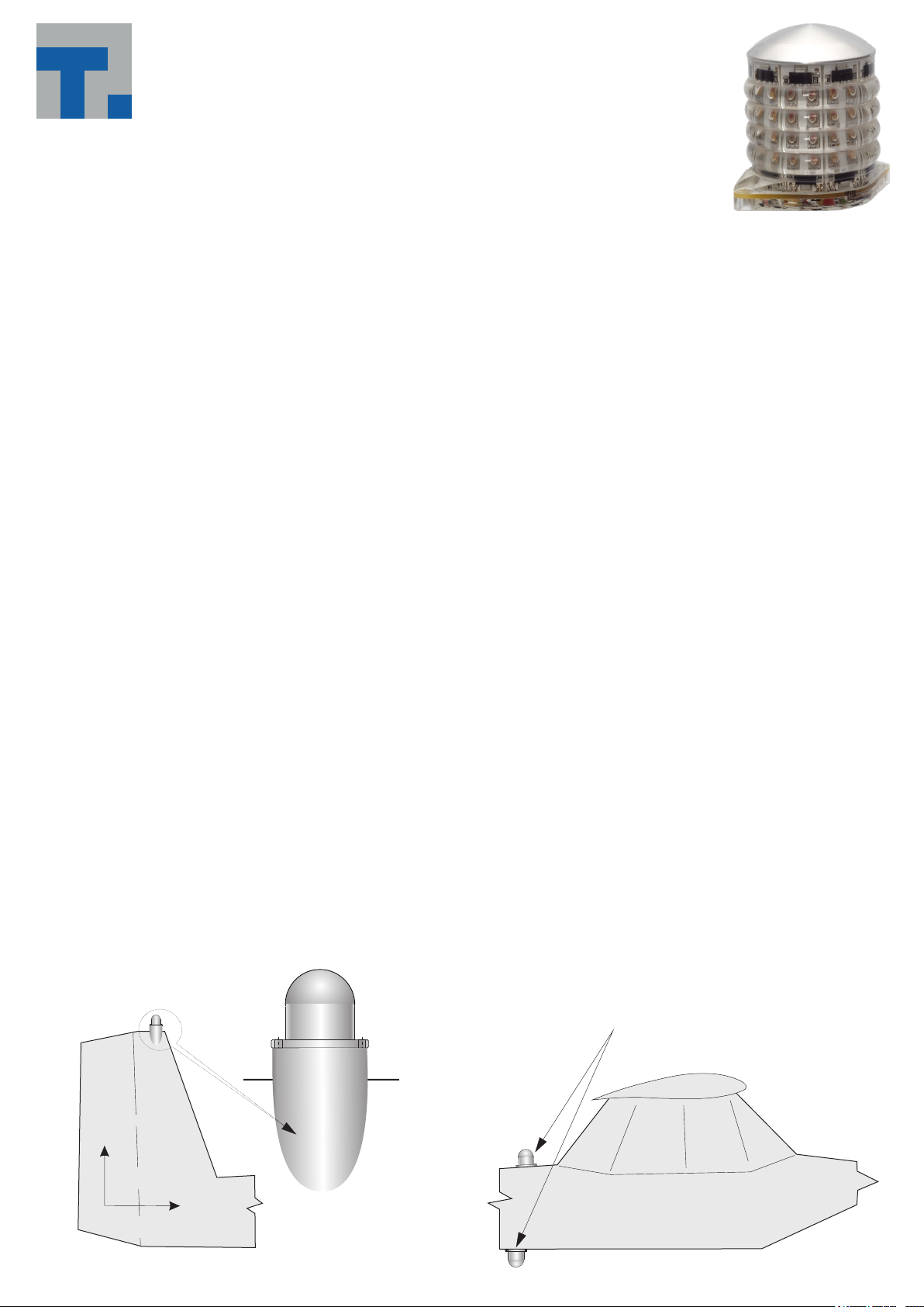
The ERB must be mounted parallel to the longitudinal axis and vertically to the yaw axis of the aircraft (see illustration 1).
2
Illustration 1
Stabilizer
vertically to
the yaw axis
longitudinal axis
Stabilizer mounting position
(wooden or
epoxy-glass resin)
modeled cone
top edge
of stabilizer
Examples of mounting position
Fuselage mounting position
Page 2
Pasting
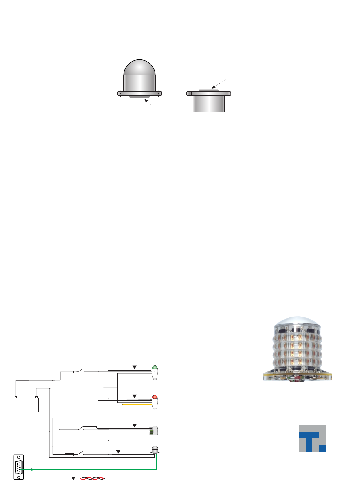
Apply only as much silicone as required to paste the ERB plane (see illustration 2).
After fixing the ERB to the required position, slightly tighten the screw. With your moistened finger using dish liquid clean off any
laterally dispensable silicon, a smooth transition can be modeled between the fuslage and the ERB.
Silicone needs time to cure (vaporization of acetic acid). The best results are achieved at a temperature of 20 deg. Celsius (68
deg. Fahrenheit). Just follow the handling instructions of the silicone. The final firmness (stability) will be reached after a few
days.
Illustration 2
mounting at the bottom of the fuselage
apply silicone here
lateral view
mounting on top of the fuselage
apply silicone here
lateral view
Electric power supply / cable connection to the aircraft system (12 Volts)
The best connection is solder with additional shrinking of the soldering joint with a shrink hose (enclosed). Only use solder for
electronic soldering never use cored solder. It contains acids which cause corrosion!
Synchronisation
The ERB2 has an additional yellow synchronisation cable to synchronize with EPL2 or EPTA. Just connect the yellow cables
(also with ELL50 where required). The intelligent synchronisation scales the light pulse (and thereby the current pulse). This will
prevent the battery respectively the generator by constant current consumption. If you do not use the synchronisation, connect
the yellow cable with +12V (red cable).
Important notes
Carefully mount the cables inside the rudder and/or the fuselage. Connect the cables professionally to the aircraft system
(red = positive, , , ) and to a 5 Amps fuse protection. Luster terminals black = negative yellow = synchronisation green = FLARM
are not suitable to connect cables. There is a good selection of suitable crimp connections in various shops.
The ERB is provided with overload protection. In case of over voltage the protector switches off the ERB. After reset or voltage
drop the ERB is again fully functional. The automatic overload protector shall be activated at a voltage above 18 Volts.
(If the voltage reduces to a value below 18 Volts, the ERB will again be functioning)
Servicing / maintenance
For additional UV protection, use varnish. Should the ERB be scratched, use a good polish to refurbish the damages. With
slightly deeper scratches use wet sandpaper with very fine granulation (800-1000) carefully polish again. Do not use aggressive
chemicals like gasoline or solvent.
For day to day cleaning use soap water!
Some insect removers and detergents forces embrittlement of epoxy based plastics and laminates. Use only aircraft certified
products. If the aircraft can not hangarized, please cover the lamps to prevent surface aging!
Technical data
Operating voltage : 10-17 volts (DC), typically 12.8 - 13.4 volts
Input : approx. 16 watts
Fuse : 5 ampere (fusible cut-out or automatic fuse)
Dimensions : 61 x 44 x 56 mms
Drill hole : 4.5 mm
Weight : approx. 105 grams with connecting cables
Warranty : 5,000 operating hours or max. 3 years
Wiring diagram:
+
12 Volt Battery
Power-FLARM-Ausgang
9 8 7 6
_
5
4
3
2 1
Verdrillte Leitungen / twisted cable
Positionslicht
Fuse 5 A
rot / red = Plus 12 Volt
schwarz / black = Minus 12 Volt
gelb / yellow = Synchronization-Cable
blau / blue = Plus 12 Volt Landescheinwerfer
grün / green = FLARM-Interface
Landescheinwerfer
Fuse 5 A
Antikollisionslicht
Switch
ACL-Funktion
=
Switch
Right
gelb / yellow
EPTA-LSA
Left
EPTA-LSA
ELL50
ETL50
ELL60
ELL80is
ACL4
ERB2
Subject to changes without notice
5.000 hours or max. 3 years
assured luminous duration
Im Tiegel 9
36367 Wartenberg
Germany
Tel.: +49 (0) 66 41 - 979 - 0
eMail: [email protected]
www.thiesen-electronics.com
www.flugzeuglichter.de
Made in Germany
TH IES EN
E L E C
TRONICS
G M B H
 Loading...