

Page 1

Ultrasonic Anemometer 2D
Operating Instructions 4.3800.00.940
1. Range of Application
The Ultrasonic Anemometer 2D is designed to detect the horizontal components of wind speed and wind
direction in two dimensions as well as the virtual temperature. Due to its very short measurement intervals,
the instrument is ideal for the inertia-free measurement of gusts and peak values.
In certain weather situations the accuracy of the air temperature measurement (virtual-temperature)
surpasses that one of the classic method where the temperature transmitter is used in a weather and thermal
radiation shield.
The measured data are available as analogue signals and as a data telegram via a serial interface.
The ultrasonic transducers as well as its carrying arms are automatically heated so that the measuring
results, in case of critical ambient temperatures, are not affected by icing rain or snow.
2. Mode of Operation
The Ultrasonic Anemometer 2D consists of 4 ultrasonic transducers, in pairs of 2 which are opposite each
other at a distance of 200 mm.
The two measurement paths thus formed are vertical to each other.
The transformers act both as acoustic transmitters and acoustic receivers.
The respective measurement paths and their measurement direction are selected via the electronic control.
When a measurement starts, a sequence of 4 individual measurements in all 4 directions of the
measurement paths is carried out at maximum possible speed.
The measurement directions (acoustic propagation directions) rotate clockwise, first from south to north, then
from west to east, from north to south and finally from east to west.
The mean values are formed from the 4 individual measurements of the path directions and used for further
calculations.
A measurement sequence takes approx. 10 msec at +20°C.
1 -12 021235/10/01
Page 2
3. Measurement Principle
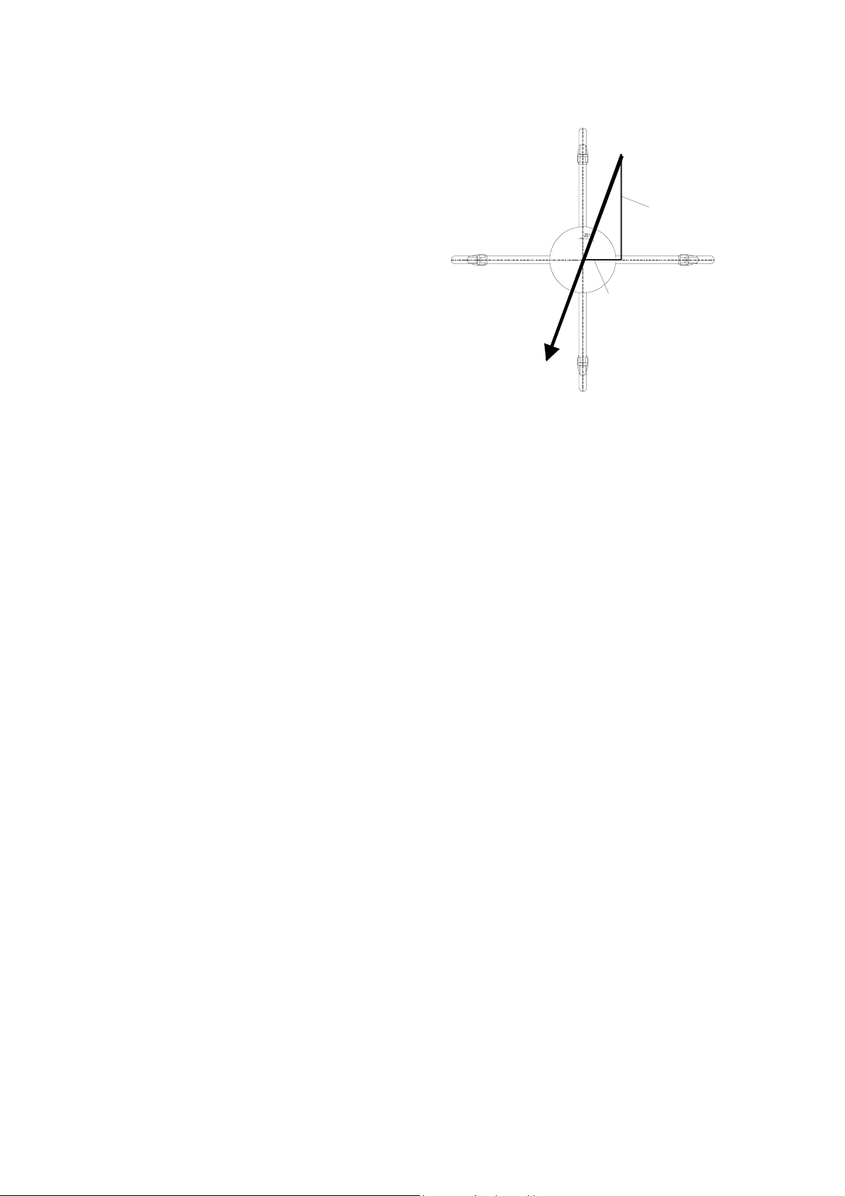
3.1 Wind speed and direction
The speed of propagation of the sound in calm air is
superposed by the speed components of an air flow in
wind direction.
N
Wind from NNE
A wind speed component in the direction of the
propagation of the sound supports the speed of
propagation, thus leading to an increase in the speed. A
Y - component
wind speed component opposite to the direction of
propagation, on the contrary, leads to a reduction of the
speed of propagation.
W
E
The speed of propagation resulting from the
superposition leads to different propagation times of the
sound at different wind velocities and directions over a
X - component
fixed measurement path.
As the speed of sound is very dependent on the air
temperature, the propagation time of the sound is
measured on both of the measurement paths in both
directions. In this way, the influence of the temperature-
S
dependent speed of sound on the measurement result
can be eliminated.
By combining the two measuring paths which are at right angles to each other, one obtains the
measurement results of the sum and the angle of the wind speed vector in the form of rectangular
components.
After the rectangular speed components have been measured, they are then transformed by the µ-processor
of the anemometer into polar co-ordinates and output as sum and angle of wind speed.
3.2 Acoustic-Virtual Temperature
As previously mentioned, the speed of the propagation of sound shows a radix dependency on the absolute
air temperature, but is rather independent of air pressure, and only slightly dependent of humidity. Thus
these physical properties of gases can be used to measure air temperature at constant and known chemical
composition.
It is a measurement of gas temperature which is made without thermal coupling to a solid state sensor.
The advantages of this measured variable is, on the one hand, its inertia free reaction to the actual gas
temperature, and, on the other hand, the avoidance of measurement errors such as those which occur when
a solid state temperature sensor is heated up by radiation.
Due to the low dependency of the speed of propagation of the sound on the air humidity, the “Virtual
Temperature” refers to dry air (0% humidity) under the same pressure conditions as that one actually
measured.
The deviation of the measured “acoustic-virtual temperature”, compared with the real air temperature, is
linear-dependent from the absolute humidity content of the air.
The part of water vapour in the air increases proportionally the sonic speed, as H
only half of the mass of the remaining air-molecules (O
and N2).
2
The rise of the sonic speed leads to an apparent (virtual) rising of the measured temperature in humid air
compared with dry air of the same temperature.
The deviation of the measured virtual temperature in humid air, compared with real air temperature, can be
corrected according to the following correlation, when the value of absolute humidity is given:
Tr = Tv – Tv * 0,135 K * m3 / g * H
abs
and Tr represents the real air temperature, T
absolute humidity in grams H
O per m³ of air.
2
the measured acoustic-virtual temperature and H
v
2 -12 021235/10/01
O-molecules have approx.
2
the
abs
Page 3
4. Technical Data
Wind Speed
Meas. range 0...65 m/s, the analogue outputs are scaled to 60 m/s !
Accuracy
± 0.1 m/s , at the range 0 ... 5 m/s
resp. ± 2 % rms from meas. value , at > 5 m/s
Wind Direction
Virtual Temperature
Data output digital
Resolution 0.1 m/s
Meas. range 0...360°
Accuracy
± 1.0°
Resolution 1°
Meas. range - 40 .... + 70 °C
Accuracy
± 0.5 K
Resolution 0.1 K
Interface RS 485 / RS 422
Baud rate 1200, 2400, 4800, 9600, 19200 selectable
Output
Instantaneous values of speed, direction and temperat.
Gliding mean values 1sec.; 10sec.; 1min.; 2min.; 10min.
Output rate 1 per 100 msec up to 1 per 25.5 sec, selectable
Status identification Heater status, Path disturbance, temperature deviation
path to path > 8 Kelvin
analogue
Output 0 ... 20 mA / 0 ... 10 V or 4 ... 20 mA / 2 ... 10 V
Only wind velocity and wind direction
General
Output
Load at current output max. 400 Ω
Load at voltage output min. 4000 Ω
Instantaneous values of wind speed and direction
Gliding mean values 1sec.; 10sec.; 1min.; 2min.; 10min.
Update rate 1 per 100 msec
Resolution 12 bit
Internal meas. rate 400 measurements per second, at 25 °C
Temp. range - 40 ... + 70 °C
Supply voltage electronics, 12 ... 24 V AC/DC ± 10%, max. 3 VA
heater , 24 V AC/DC ± 10%, max. 70 VA
Protection IP 65
Icing acc. to THIES STD 012001
Corrosion No corrosion after 3 month of salt fog and condensation
EMV EN 55022 5/95 class B; EN50082-2 2/96
Model V4A Stainless steel for housing and sensor arms
Mounting to a mast tube 1
½ ”, for ex. DIN 2441
Type of connection 16 pole plug connection in the shaft
Weight approx. 2.5 kg
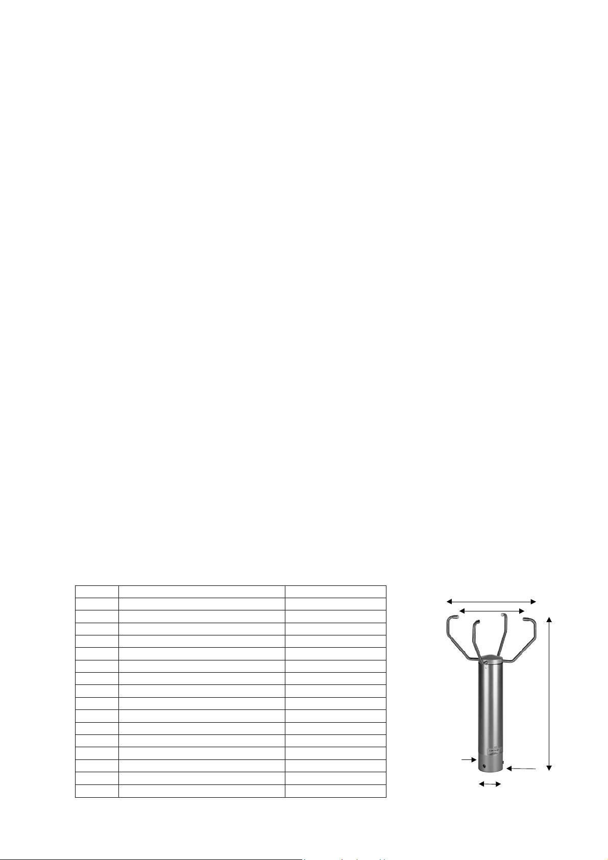
5. Plug Connection Assignment Scale Drawing
Pin-No. Function Remark
1 (A)
2 (B)
3 (C)
4 (D)
5 (E)
6 (F)
7 (G)
8 (H)
9 (I)
10 (K)
11 (L)
12 (M)
13 (N)
14 (O)
15 (P)
16 (R)
Analogue output current WV 0 / 4 – 20 mA
Analogue output current WD 0 / 4 – 20 mA
Analogue Ground AGND
Analogue output voltage WV 0 / 2 – 10 V
Analogue output voltage WD 0 / 2 – 10 V
TX+ serial interface
RX+ serial interface
GND serial interface
RX- serial interface
TX- serial interface
Power electronics 12 ... 24V AC/DC
Power electronics 12 ... 24V AC/DC
Power heater 24 V AC/DC bridged with PIN 14
Power heater 24 V AC/DC bridged with PIN 13
Power heater 24 V AC/DC bridged with PIN 16
Power heater 24 V AC/DC bridged with PIN 15
Mounting shaft
for mast tu be 1½“
40 mm dept h
3 -12 021235/10/01
Ø 70
275
200
16 pol.
plug
in the shaft
422
Page 4

5.1 Remarks concerning Power Supply of Instrument:
The connecting cables for the heating (13 u. 14; 15 u. 16) must be bridged on the supply side in order to
guarantee the complete heating power!
The electronics is additionally supplied uncoupled via diodes through the heating connections 13,14, and 15,
16.
If the heating voltage exceeds the supply voltage the heating voltage takes on the supply of the electronics.
6. Interface Description
6.1 Telegram forms
6.1.1 Telegram VD (STX)xx.x xxx*xx(CR)(ETX)
Z. NR. FUNCTION
1 STX (HEX 02)
2 101 Wind speed
3 100 Wind speed
4 “.” Decimal point
5 10-1 Wind speed
6 space (HEX 20)
7 102 Wind direction
8 101 Wind direction
9 100 Wind direction
10 * (HEX 2A) Check sum identifier
11 High Byte check sum in HEX
12 Low Byte check sum in HEX
13 CR (HEX 0D) Carriage return
14 ETX (HEX 03)
6.1.2 Telegram VDT (STX)xx.x xxx xxx.x x*xx(CR)(ETX)
Z. NR. FUNCTION
1 STX (HEX 02)
2 101 Wind speed
3 100 Wind speed
4 “.” (HEX 2E) Decimal point
5 10-1 Wind speed
6 Space (HEX 20)
7 102 Wind direction
8 101 Wind direction
9 100 Wind direction
10 Space (HEX 20)
11 + or - sign
12 101 Temperature
13 100 Temperature
14 “.” (HEX 2E) Decimal point
15 10-1 Temperature
16 Space (HEX 20)
17 High Byte status byte
18 Low Byte status byte
19 * (HEX 2A) Check sum identifier
20 High Byte Check sum in HEX
21 Low Byte Check sum in HEX
22 CR (HEX 0D) Carriage return
23 ETX (HEX 03)
4 -12 021235/10/01
Page 5

6.1.3 Telegram V4DT (STX)xxx.x xxx xxx.x x xx*xx(CR)(ETX)
Z. NR. FUNCTION
1 STX (HEX 02)
2 102 Wind speed
3 101 Wind speed
4 100 Wind speed
5 . (HEX 2E) Decimal point
6 10-1 Wind speed
7 Spare (HEX 20)
8 102 Wind direction
9 101 Wind direction
10 100 Wind direction
11 Space (HEX 20)
12 + or - Sign
13 101 Temperature
14 100 Temperature
15 . (HEX 2E) Decimal point
16 10-1 Temperature
17 Space (HEX 20)
18 K, N, M, S = km/h, Knots, m/s, mph
19 Space (HEX 20)
20 High Byte Status byte
21 Low Byte Status byte
22 * (HEX 2A) Check sum identifier
23 High Byte Check sum in HEX
24 Low Byte Check sum in HEX
25 CR (HEX 0D) Carriage return
26 ETX (HEX 03)
6.1.4 Telegram NMEA V 2.0 $WIMWV,xxx.x,R,xxx.x,N,A*xx(CR)(LF)
5 -12 021235/10/01
Z. NR. FUNCTION
1 $ (HEX 24) Dollar
2 W (HEX 57)
3 I (HEX 49)
4 M (HEX 4D)
5 W (HEX 57)
6 V (HEX 56)
7 , (HEX 2C) Comma
8 102 Wind direction
9 101 Wind direction
10 100 Wind direction
11 . (HEX 2E) decimal point
12 10-1 Wind direction
13 , (HEX 2C) Comma
14 R (HEX 52)
15 , (HEX 2C) Comma
16 102 Wind speed
17 101 Wind speed
18 100 Wind speed
19 . (HEX 2E) Decimal point
20 10-1 Wind speed
21 , (HEX 2C) Comma
22 K, N, M, S = km/h, Knots, m/s, mph
23 , (HEX 2C) Comma
24 A, V A = valid, V = non valid
25 * (HEX 2A) Check sum identifier
26 High Byte Check sum in HEX
27 Low Byte Check sum in HEX
28 CR (HEX 0D) Carriage Return
29 LF (HEX 0A) Line Feed
Page 6

6.2 Definition of Checksum and Status byte
6.2.1 Forming of Checksum
The checksum is the result of the byte-wise EXOR-combination of the bytes output in the telegram.
The EXOR-combination comprises all bytes between the telegram start sign „STX”, or “$” within the NMEAtelegram, and the byte “*” as identifier for starting the checksum.
Thus, the bytes „STX“ or. „$“ and „* “ will not be taken into consideration with the checksum calculation!
6.2.2 Definition of Status Byte
The status byte contains information about the current state of the system.
The information comprises:
• error events with the measurement value acquisition
• a possible de-calibration caused, e.g., by a change in the measurement path length
(due to mechanical deformation of the transducer carrying arms)
• the operation state of the instrument heating.
Bit 0 0 = no error 1 = general error event, measurement value probably
correct, measurement value acquisition disturbed
Bit 1 0 = no error 1 = error event, deviation of the virtual temperature
between both measurement paths is > 8 K.
Bit 2 reserved
Bit 3 0 = heating switched off 1 = Heating switched on
Bit 4 to 7 reserved
The error event reported by Bit 0 does not necessarily cause the output of an erroneous measurement value.
Certain weather conditions like extreme precipitation and snowfall may disturb the measurement acquisition
for a short time, caused by sonic burst-echoes at the precipitation particles.
Such an event, however, is realized by a plausibility-algorithm, which leads to an immediate re-measurement
of the instrument – until a correct value is available.
The output measurement value is generally correct, in spite of the reported error, and does not contain the
erroneous data.
If Bit 1 is continuously set during the operation, you should reckon on a de-calibration of the instrument due
to mechanical deformation of the measurement arms.
6.3 Telegram Output Format and Analogue Value Output in Case of Error Events
In the following cases the digital telegram outputs „F“ as measurement value figure instead of numbers:
• If the measurement acquisition is constantly disturbed for more than 10 seconds in spite of multiple
measurements
• If the deviation of the virtual temperature between both measurement paths is > 8 K.
In this case the analogue outputs are set on the maximum voltage-/current value(10V, 20mA).
6 -12 021235/10/01
Page 7

7. Averaging Procedure:
The Ultrasonic 2D forms the gliding mean value through a FIFO-memory the capacity of which comprises up
to 600 values.
In the free running measurement mode the measurement data rate is exactly 10 Hz or 100msec, and forms,
at the same time, the updating rate for the averaging memory (FIFO-memory).
If averaging is requested the measured data are recorded in the FIFO-memory stated above, the capacity of
which is built-up depending on the selected averaging period.
If the averaging period is, for example, 10 seconds, 100 memory cells are used, and in case of an averaging
period of 1 minute 600 cells.
From a selected averaging period > 1 minute up the data flow will be pre-averaged; because the memory
capacity of 600 values cannot be exceeded.
The Ultrasonic 2 D combines two different and useful procedures of mean value forming:
• The forming of vectorial mean values
• The forming of scalar mean values
These different procedures can be selected for the averaging of both the wind speed and wind direction,
depending on the application.
The procedure of forming the vectorial mean value takes the wind direction into account when averaging the
wind speed and vice versa.
Thus, the averaged dimensions of wind speed and wind direction are valued each one with the other.
This procedure of forming the mean value is well suited, for example, for measurements and analysis of
pollutant-propagation.
The procedure of forming the scalar mean value averages both dimensions of wind speed and wind direction
independently from each other.
These averaging procedures lead to results comparable with mechanical wind speed- and wind direction
transmitters.
The scalar averaging procedure is suited, for example, for location-analysis for wind power plants, where only
the dimension of the wind vector – important for power generation – is interesting but not its direction.
The vectorial and scalar procedure can be used independently with wind speed and wind direction within an
output telegram.
For this, you have to select one of the four possible combinations through the command AM (Average
Method).
Command for selecting the averaging procedure:
AM00000 (Average Method) vectorial averaging of speed and direction
AM00001 scalar averaging of speed and direction
AM00002 scalar averaging of speed and vectorial averaging of direction
AM00003 vectorial averaging of speed and scalar averaging of direction
7 -12 021235/10/01
Page 8

8. Bus-Ability, Synchronisation of the Measurement on the Query Telegram:
8.1 Duplex-Mode
The Ultrasonic supports absolutely any operation at an RS485/RS422 data bus in co-operation with further
instruments (bus operation).
Supported are both semi-duplex bus-topologies and full duplex bus-systems.
In the semi- and full duplex operation the line drivers of the Ultrasonic are active only for the time of data
transmission.
The remaining time the line drivers are off-line (“three-state-mode”).
The direct connection to a PC with RS232 interface makes an interface-converter RS 485 / RS 232
necessary, e.g. our accessories order-no. 9.1702.20.000
Command for Selecting the duplex-mode (DM for duplex mode):
DM00000 for semi-duplex (2-wire operation)
DM00001 for full duplex (4-wire operation) (state of delivery).
In case of bus operation a spontaneous output of the Ultrasonic is suppressed – the instruments respond
only on request of the bus master.
When semi-duplex operation is set, a spontaneous telegram output is not selectable.
In case the spontaneous telegram output has been selected erroneously this could lead to a blocking of the
receivers at slow baud rates.
8.2 Synchronisation on Data Query
Certain application make it necessary to interrogate cyclically a collective of instruments within a short time
(e.g. 5 instruments within 100 ms).
There might be the following problem: the Ultrasonic can be contacted during a measurement by the
asynchronous query and is then not ready for transmission.
In order to guarantee an immediate instrument response without delay, the possibility of temporal
measurement synchronisation on the query is used.
Command for activating the ability for measurement-synchronisation on the query:
MT00001 (Measurement Trigger) Synchronisation Ability on.
MT00000 Synchronisation Ability off.
In case the instrument receives, with active synchronisation, a telegram inquiry through the command
TR0000x, and further inquiry follow with intervals of less than 2,5 seconds, the instrument runs
synchronously to the inquiries and responds with smallest possible delay.
If there are no queries for more than 2,5 seconds, the instrument leaves the synchronous mode and changes
into a spontaneous measurement value acquisition.
This return to the spontaneous mode of measurement guarantees that all control functions derived from the
measurement data (e.g. switch-on heating etc.) will be able to operate also in case of a failure of query
telegram.
As soon as a new query occurs in the spontaneous mode the instrument synchronises immediately on the
query telegram.
8.3 Averaging with Active Synchronisation
In case the measurement values should be averaged please take care that – with active synchronisation –
the exact, internal time basis of 100 ms for forming the measurement values is not used. In this case, the
time is determined by the query-repetition-rate.
It is advisable to switch-off the synchronisation ability if it is not absolutely necessary.
8 -12 021235/10/01
Page 9

9. List of control commands
The Anemometer 2D can be controlled via its serial data interface using the commands in the following list.
Any standard terminal program such as “procomm“ , “telix“ or a Windows terminal program (e.g. “Hyper
Terminal” ) can be used.
All adjustments are stored in a E²ROM so that the adjusted parameters cannot get lost after switching
off or failure of power supply.
9.1 List of commands
Command Function Remark
<ID> AM 00000 Vectorial averaging
<ID> AM 00001 Scalar averaging
<ID> AM 00002 Scalar / vectorial averaging
<ID> AM 00003 Vectorial / Scalar averaging
<ID> AV 00000 Instantaneous value
<ID> AV 00001 Mean value over 1 second
<ID> AV 00002 Mean value over 10 seconds
<ID> AV 00003 Mean value over 1 minute
<ID> AV 00004 Mean value over 2 minutes
<ID> AV 00005 Mean value over 10 minutes
<ID> BR 00002 1200 Baud N 8 1
<ID> BR 00010 1200 Baud E 7 1
<ID> BR 00003 2400 Baud N 8 1
<ID> BR 00011 2400 Baud E 7 1
<ID> BR 00004 4800 Baud N 8 1
<ID> BR 00012 4800 Baud E 7 1
<ID> BR 00005 9600 Baud N 8 1
<ID> BR 00013 9600 Baud E 7 1
<ID> BR 00006 19200 Baud N 8 1
<ID> BR 00014 19200 Baud E 7 1
<ID> DM 00000 Duplex mode half duplex
<ID> DM 00001 Duplex mode full duplex
<ID> ES 00000 Sign-echo switched off
<ID> ES 00001 Sign-echo switched on
<ID> KY 00000 Key, no access
<ID> KY 00001 Key, open access
<ID> MT 00000 Measurement trigger off
<ID> MT 00001 Measurement trigger on
<ID> LT 00000 Interface selection
<ID> LT 00001 Interface-selecting
<ID> NC 00xxx North correction in 1°
<ID> OR 00xxx Output rate online (spontaneous)
<ID> OS 00000 Wind speed in m/s
<ID> OS 00001 Wind speed in Km/h
<ID> OS 00002 Wind speed in mph
<ID> OS 00003 Wind speed in Knots
<ID> SC 00000 Start value of current 0mA
<ID> SC 00001 Start value of current 4mA
<ID> TR 00000 no Telegram on request
<ID> TR 00001 Telegram VD on request
<ID> TR 00002 Telegram VDT on request
<ID> TR 00003 Telegram V4DT on request
<ID> TR 00004 Telegram NMEA on request
<ID> TT 00000 No telegram output
<ID> TT 00001 Telegram VW spontaneous
<ID> TT 00002 Telegram VDT spontaneous
<ID> TT 00003 Telegram V4DT spontaneous
<ID> TT 00004 Telegram NMEA V 2.0
Remark:
9 -12 021235/10/01
Vectorial averaging of wind speed and direction
Scalar averaging of wind speed and direction
Scalar averaging of speed / vectorial averaging of direction
Vectorial averaging of speed / scalar averaging of direction
Output of the instantaneous values
Output of the gliding mean value over 1 second
Output of the gliding mean value over 10 seconds
Output of the gliding mean value over 1 minute
Output of the gliding mean value over 2 minutes
Output of the gliding mean value over 10 minutes
Data rate 1200 Baud, 8 Data bits, No Parity, 1 Stop bit
Data rate 1200 Baud, 7 Data bits, Parity Equal, 1 Stop bit
Data rate 2400 Baud, 8 Data bits, No Parity, 1 Stop bit
Data rate 2400 Baud, 7 Data bits, Parity Equal, 1 Stop bit
Data rate 4800 Baud, 8 Data bits, No Parity, 1 Stop bit
Data rate 4800 Baud, 7 Data bits, Parity Equal, 1 Stop bit
Data rate 9600 Baud, 8 Data bits, No Parity, 1 Stop bit
Data rate 9600 Baud, 7 Data bits, Parity Equal, 1 Stop bit
Data rate 19200 Baud, 8 Data bits, No Parity, 1 Stop bit
Data rate 19200 Baud, 7 Data bits, Parity Equal, 1 Stop bit
Half duplex, 2-wire operation
Full duplex, 4-wire operation
Echo operation of transmitted characters switched off
Echo operation of transmitted characters switched on
Software-key, access to EEPROM closed
Software- key, access to EEPROM open
No synchronization of measurement onto request poss.
Synchronization of measurement onto request possible
Interface standard RS 485 (RS 422)
Interface standard RS 232
Input of north correction, value range 00000 up to 00360
Output rate xxx times 100ms, value range 00001 up to 00255
Scale of Wind speed in meter per second
Scaling of Wind speed in kilo meter per hour
Scaling of Wind speed in miles per hour
Scaling of Wind speed in knots (nautically)
Analogue output current 0 - 20mA / 0 – 10 V
Analogue output current 4 - 20mA / 2 – 10 V
single output of the telegram form, see 6.1.1
single output of the telegram form, see 6.1.2
single output of the telegram form, see 6.1.3
single output of the telegram form, see 6.1.4
Online output of telegram form, see 6.1.1
Online output of telegram form, see 6.1.2
Online output of telegram form, to 6.1.3
Online output of telegram form, to 6.1.4
Page 10

Due to the compatibility the telegrams VD and VDT supply the wind speed in 3 digits form
In order to avoid that the measuring range is exceeded the telegrams deliver the wind speed exclusively in
the unit of m/s (meters per second)!
9.2 Command Input
Please find your ID (identifier-number) in the works certificate included in the delivery.
For the input of commands and parameters please open first the access to the EEPROM by entering the
command (ID) KY00001.
After all inputs have been made the access to the EEPROM should be locked again through the command
(ID) KY00000 in order to avoid unauthorised changes of the system parameters.
The command is input by entering the instrument identification number (ID) followed by two letters which
specify the actual command followed by a 5-digit code number respective value.
The characters are entered without a space and are activated with Return.
Entering the command without the 5-digit code number is interpreted as a query of the command status and
leads to the output of the current command status.
Correcting the command word during input when an error has occurred is not allowed and the command
will not be accepted.
All letters must be capitalised, otherwise they will not be accepted.
Example:
Correcting an angle of displacement while setting up the anemometer by entering a corrective
angle:
Instrument ID is accepted as 12. The necessary angular correction is 47°. The angle stored in
the system up to that time was 15°. Attention: Input and representation in units of 1°.
The correction angle is added clockwise to the measured wind direction angle.
Input: 12NC System response: !12NC00015
Input: 12NC00047 System response: !12NC00047
The system verifies the accepted input and displays the set value.
Attention: After the supply voltage of the instrument has been switched on or switched off the
locking is automatically activated.
For bus operation in RS485 interface mode the permanent output of the measuring data must be stopped
through the command (ID)TT00000. In addition, the echo operation for characters ES00000 must be
switched off in order to avoid a bus conflict.
A single data telegram can then be called in through the command (ID)TR0000(x) in a telegram form
described under item 6.1.
The „X“ in the command string means the selected telegram form (1, 2 or 3).
The ID-number selects the required instrument.
9.3 Pre-setting of Instruments (Models for Delivery)
Order-No. Output parameter Remarks / Connecting to:
4.3800.00.140
4.3800.00.141
4.3800.00.340
4.3800.00.341
4.3800.00.540
RS485 / 422, 0-20 mA / 0 - 10 V , VDT, 1200 E 7 1 LED Display 4.32xx.xx.2xx
RS485 / 422, 4-20 mA / 2 - 10 V , VDT, 1200 E 7 1 LED Display 4.32xx.xx.2xx
RS485 / 422, 0-20 mA / 0 - 10 V , VDT, 9600 N 8 1 Online Wind 9.1700.97.010
RS485 / 422, 4-20 mA / 2 - 10 V , VDT, 9600 N 8 1 Online Wind 9.1700.97.010
RS485 /422, 0-20 mA /0- 10V ,NMEA 2.0, 4800 N 8 1 NMEA V2.0
4.3800.00.640
4.3800.00.641
4.3800.00.940
RS485 / 422, 0-20 mA / 0-10 V, TR, 1200 E 7 1, FD TDL 14, COM 2 9.1740.1X.50X
RS485 / 422, 4-20 mA / 2-10 V, TR, 1200 E 7 1, FD TDL 14, COM 2 9.1740.1X.50X
RS485 / 422, 0-20 mA / 0-10 V, VDT, 9600 N 8 1,
OR = 1 sec AV = 1 sec
FD
10 -12 021235/10/01
Page 11

10. Preparation for Use
10.1 Selecting the Site
As already described above the ultrasonic anemometer transmits sonic bursts which are necessary for the
measurement of the propagation speed. If these sonic bursts hit a well sonic-reflecting surface they are
reflected as echo and might cause error measurements – under unfavourable conditions.
It is, therefore, advisable to install the US-anemometer with a minimum distance of 1 meter to objects in the
measurement area.
In general wind measurement instruments should be able to detect the wind conditions over a wide area. In
order to obtain comparative values when determining the surface wind, measurements should be taken at a
height of 10 meters above a plane, unobstructed area. An unobstructed area is one where the distance
between the wind transmitter and any obstacle is at least 10 times greater than the height of the obstacle. (s.
VDI (German Engineers Association) 3786). If this requirement cannot be fulfilled, then the wind
measurement instrument should be set up at a height where the measured values are not influenced by any
local obstacles (approx. 6-10 m above the level of the obstacle). The anemometer should be set up in the
center of flat roofs, not at the edge in order to avoid possible preferred directions.
10.2 Mounting the wind transmitter
The wind transmitter can be mounted to a pipe piece of R 1 ½" (Ø 48.3 mm) which is 50 mm long. The
internal diameter of the pipe must be at least 40 mm as the wind transmitter is connected electrically from
below with a plug. Solder a flexible control line LiYCY with the corresponding number of cores to the
enclosed plug. After the wind transmitter has been connected, set it onto the pipe piece respectively the mast
piece and align to North with the north sensor marking (red ring at the sensor). To do this, take a bearing via
the ultrasonic transducer of the North/South path onto an object to the North, for example a building or a
special geographic feature. Use the four screws with hexagonal recessed holes (SW 4 mm) to attach the
instrument to the shaft.
Note : When using a lightning rod please take care that it is mounted always in an angle of
45° to the measuring distance, as otherwise there might be deviations of measuring
value.
10.3 North Alignment
For the alignment of the anemometer the red marking of the sensor must indicate to the North. For this,
you select an obvious point in a northerly or southerly direction in the surroundings with the aid of a compass;
then turn the mast or the anemometer into this direction until both arms opposite are situated in a straight
line.
It is also possible that oneself stands in a northerly or southerly direction with respective distance, and a
partner turns the anemometer or mast by command until both sensor arms are situated in a straight line.
In this case, it is advisable to use a pair of field glasses.
11. Accessories
Connecting cable, complete 506 702
15 m cable with connecting plug
PC Software Online Wind 9.1700.97.010
Power Supply Unit 9.3388.00.000
RS 232 / RS 422 converter 9.1702.20.000
Lightning Rod 4.3100.99.000
11 -12 021235/10/01
For visualization of data on PC screen
For the power supply of the Ultrasonic
For signal conversion of RS 422 in RS 232
For lightning protection
Page 12

@
12. Maintenance
As the instrument has no moving parts i.e. operates without wear or tear, only minimal maintenance is
required. As the sensor surface is permanently washed up by the falling rain it is only occasionally necessary
to clean the surface with non-aggressive cleansing agent and soft cloth. These cleansing activities can be
carried out – as far as necessary – on occasion of the routine checks.
13. Calibration
The ultrasonic anemometer does not contain any adjustable components such as electrical or mechanical
trimming elements. All of the components and materials are invariant in time. Thus, regular calibration
because of ageing is not required. Only a mechanical deformation of the transformer arms and the resulting
changes in the length of the measurement paths lead to errors in the measured values.
The virtual temperature can be used to check the length of the measurement path. A change in the
measurement path length of 0.17% and consequently a measurement error of 0.17% of the wind speed
corresponds to a 1 K deviation of the virtual temperature at 20 °C, thus at 6 K deviation, the measurement
error of wind speed is approx. 1%.
If the distance of measuring path of the anemometer is de-aligned please contact the producer for a recalibration of the instrument.
14. Warranty
Damages resulting from improper handling or caused by external influences, e.g. lightning, are excluded from
the warranty. The warranty expires if the instrument has been opened.
Attention :
A return of the instruments must be effected in the original packing as otherwise the
guarantee expires in case of mechanical damages e.g. by deformation of the
transducer arms.
ADOLF THIES GmbH & Co. KG
Hauptstraße 76 37083 Göttingen Germany
P.O. Box 3536 + 3541 37025 Göttingen
Phone ++551 79001-0 Fax ++551 79001-65
www.thiesclima.com info
12 -12 021235/10/01
- Alterations reserved -
thiesclima.com
 Loading...