

Thies CLIMA Hygro-Thermo Transmitter-compact Instructions For Use Manual
Instruction for use
020727/08/13
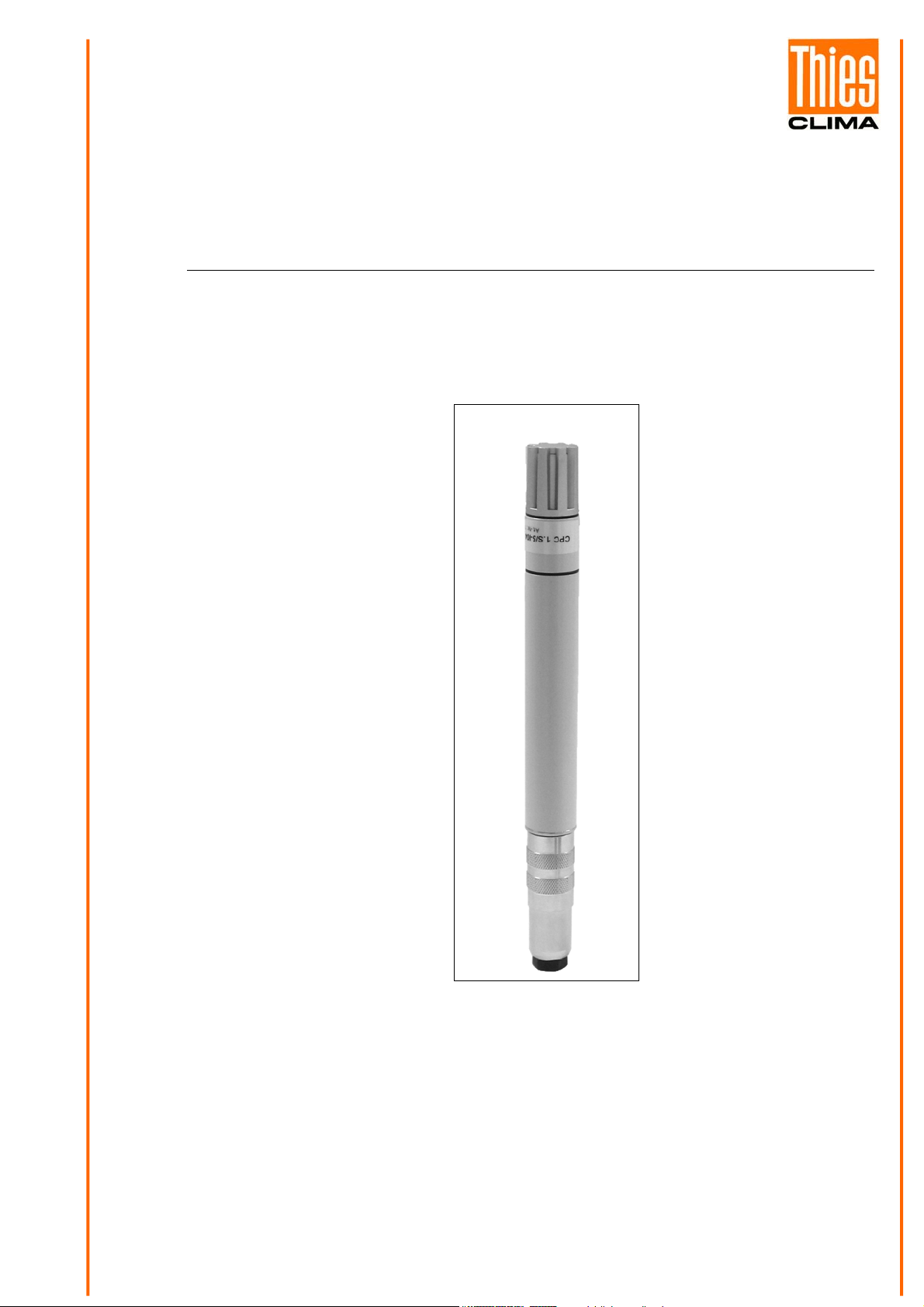
Hygro-ThermoTransmitter-compact
1.1005.54.780 / 781/ 782
ADOLF THIES GmbH & Co. KG
Hauptstraße 76 37083 Göttingen Germany
Box 3536 + 3541 37025 Göttingen
Phone +49 551 79001-0 Fax +49 551 79001-65
THE WORLD OF WEATHER DATA - THE WORLD OF WEATHER DATA - THE WORLD OF WEATHER DATA
www.thiesclima.com info@thiesclima.com
Safety Instructions
• Before operating with or at the device/product, read through the operating instructions.
This manual contains instructions which should be followed on mounting, start-up, and operation.
A non-observance might cause:
- failure of important functions
- Endangering of persons by electrical or mechanical effect
- Damage to objects
• Mounting, electrical connection and wiring of the device/product must be carried out only by a qualified technician
who is familiar with and observes the engineering regulations, provisions and standards applicable in each case.
• Repairs and maintenance may only be carried out by trained staff or Adolf Thies GmbH & Co. KG. Only
components and spare parts supplied and/or recommended by Adolf Thies GmbH & Co. KG should be used for
repairs.
• Electrical devices/products must be mounted and wired only in voltage-free state.
• Adolf Thies GmbH & Co KG guarantees proper functioning of the device/products provided that no
modifications have been made to the mechanics, electronics or software, and that the following points are
observed:
• All information, warnings and instructions for use included in these operating instructions must be taken into
account and observed as this is essential to ensure trouble-free operation and a safe condition of the measuring
system / device / product.
• The device / product is designed for a specific application as described in these operating instructions.
• The device / product should be operated with the accessories and consumables supplied and/or recommended
by Adolf Thies GmbH & Co KG .
• Recommendation: As it is possible that each measuring system / device / product under certain conditions, and
in rare cases, may also output erroneous measuring values, it is recommended using redundant systems with
plausibility checks with security-relevant applications.
Environment
• As a longstanding manufacturer of sensors Adolf Thies GmbH & Co KG is committed to the
objectives of environmental protection and is therefore willing to take back all supplied products
governed by the provisions of "ElektroG"
and to perform environmentally compatible disposal and recycling. We are prepared to take
back all Thies products concerned free of charge if returned to Thies by our customers
carriage-paid.
• Make sure you retain packaging for storage or transport of products. Should packaging
however no longer be required, arrange for recycling as the packaging materials are designed
to be recycled.
(German Electrical and Electronic Equipment Act)
Documentation
• © Copyright Adolf Thies GmbH & Co KG, Göttingen / Germany
• Although this operating instruction has been drawn up with due care, Adolf Thies GmbH & Co KG can accept
no liability whatsoever for any technical and typographical errors or omissions in this document that might
remain.
• We can accept no liability whatsoever for any losses arising from the information contained in this document.
• Subject to modification in terms of content.
• The device / product should not be passed on without the/these operating instructions.
2 - 14 020727/08/13

Contents
1 Models available ........................................................................................................................ 3
2 Application ................................................................................................................................. 4
3 Mounting .................................................................................................................................... 4
4 Connection................................................................................................................................. 5
4.1 Connector Pin Assignment.................................................................................................. 5
4.2 Cable Assignment ............................................................................................................... 5
5 Maintenance .............................................................................................................................. 5
6 Notes on sensors with MODBUS-RTU ...................................................................................... 6
6.1 Serial format and transfer rate............................................................................................. 6
6.2 Overview of available MODBUS registers........................................................................... 6
6.3 Configuration of MODBUS address .................................................................................... 7
6.4 Reading the measured values............................................................................................. 7
6.5 Use of internal termination................................................................................................... 8
7 Address programming methods ................................................................................................. 8
7.1 In the test network ............................................................................................................... 8
7.2 In the operating network (remotely controlled) .................................................................... 9
8 Technical Data......................................................................................................................... 10
9 Accessories / spare part (optional) .......................................................................................... 11
10 EC-Declaration of Conformity............................................................................................... 12
1 Models available
Order-No. Measuring
Range
1.1005.54.780 0...100% r. F.
-40... +85°C
1.1005.54.780 0...100% r. F.
-40... +85°C
1.1005.54.780 0...100% r. F.
-40... +85°C
Electrical
Output
RS 485
MODBUS RTU
RS 485
MODBUS RTU
RS 485
MODBUS RTU
Operating
Voltage
5...30V DC ZE20
5...30V DC ZE20
5...30V DC ZE20
Sensor
protective filter
Construction /
Connection
- H-T-Transmitter
with plug and
mating plug
- H-T-Transmitter
plug connection
- mating plug with
5 m cable and
wire end
- H-T- Transmitter
plug connection
- mating plug with
10 m cable and
wire end
This hygro-thermo transmitter has a digital RS 485 output, and is suited for the data transmission
acc. to MODBUS RTU protocol.
3 - 14 020727/08/13

2 Application
The Hygro-Thermo Transmitters of our compact series are designed to measure relative humidity,
the temperature of the air and other non-aggressive gases.
The use of capacitive humidity sensors is a guarantee for:
• a high degree of long-term stability
• nearly linear characteristics
• good dynamic behaviour
• dewing stability
• low temperature coefficients
• low hysteresis
The hygro-thermo transmitter is equipped with a protective filter for the sensors.
Type: Membrane-filter with gauze ZE20 (order-no. 1.1005.54.901) for protection against
dust in case of field application.
Remark:
For filed work, it is advisable to use a „Weather and Thermal Radiation Shield“. It
is optionally available as accessory.
3 Mounting
For correct measurements, the Hygro-Thermo Transmitter should be mounted at a site in the room
which is representative of the climate within the room. The mounting position itself is arbitrary.
Mount the sensor such that water cannot penetrate the inside of the sensor. Dewing and sprinkling
water do not damage the sensor.
Moreover, please make sure to keep the operating voltages as well as a good recirculation
ventilation of the instrument. Deviations might lead to measurement errors (for example: due to
instrument warming).
Preferably, the sensor should be mounted vertically facing downwards to a wall (indoor application),
and should be mounted horizontally facing backwards in canals.
4 - 14 020727/08/13
4 Connection
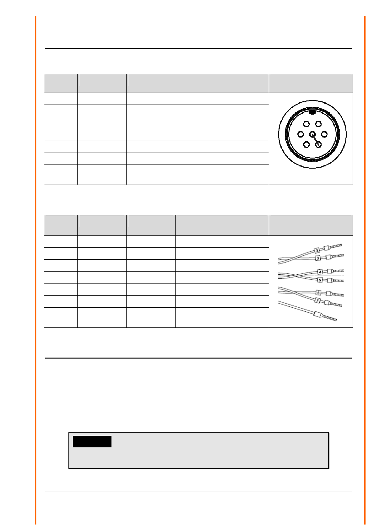
4.1 Connector Pin Assignment
Pin Description Function
1 reserved
2 D0/A/Data+ MODBUS RS485 Data+
3 D1/B/Data- MODBUS RS485 Data-
4 Vcc Supply voltage +
5 GND Supply voltage 0V
6 reserved
7 Termination Termination active, when Pin 3 and Pin 7
connected
4.2 Cable Assignment
Code
ring
2 Brown D0/A/Data+ MODBUS RS485 Data+
3 Black D1/B/Data- MODBUS RS485 Data-
Lead color Description Function
Postion of connections
at the sensor
6 1
5 2
4 3
Lead color marking
4 Red Vcc Supply voltage +
5 Black GND Supply voltage 0V
6 Orange D0/A/Data+ MODBUS RS485 Data+
7 Black D1/B/Data- MODBUS RS485 Data-
-- Green/yellow shield
5 Maintenance
The Hygro-Thermo Transmitter is supplied already adjusted and its characteristics remain stable for
years.
Dust does not damage the humidity sensor but does influence the dynamic behaviour negatively. If
the instrument is very dirty, the sensor element can be cleaned or carefully rinsed in distilled water.
Make sure you do not touch the highly-sensitive sensor element.
Before cleaning the sensor elements please remove the protecting filter; it should be cleaned, as
well or should be replaced.
Attention:
The instrument housing with the electronics included should
be opened only in the factory.
5 - 14 020727/08/13
 Loading...