

Page 1
Instruction for Use
021579/06/09
Datalogger DLx-MET
9.1756.x0.x0x
Software Version V1.01
9.1756.00.000
9.1756.00.100
ADOLF THIES GmbH & Co. KG
Hauptstraße 76 37083 Göttingen Germany
Box 3536 + 3541 37025 Göttingen
Phone ++551 79001-0 Fax ++551 79001-65
www.thiesclima.com info@thiesclima.com
THE WORLD OF WEATHER DATA - THE WORLD OF WEATHER DATA - THE WORLD OF WEATHER DATA
Page 2

Contents
1 MODELS.................................................................................................................................... 4
2 CONSTRUCTION OF THE DATALOGGER .............................................................................. 4
2.1 MOUNTING......................................................................................................................... 8
2.1.1 Wall-mounting............................................................................................................... 9
2.1.2 Mast-installation for case version B ............................................................................ 11
2.1.3 Cable gland................................................................................................................. 12
2.1.4 Accumulator................................................................................................................ 13
2.1.5 Mains supply............................................................................................................... 13
2.1.6 Solar panel.................................................................................................................. 14
2.1.7 DCF-Active Antenna (9.1760.00.000)......................................................................... 15
2.1.8 Remove Front Plate.................................................................................................... 15
2.1.9 Setting Digital Input..................................................................................................... 16
2.1.10 Setting Resistors Serial Interfaces .......................................................................... 17
3 OPERATION............................................................................................................................ 18
3.1 DISPLAY OPTIONS .......................................................................................................... 18
3.2 CHANGING PARAMETERS ............................................................................................. 29
3.2.1 STATION NAME ......................................................................................................... 29
3.2.2 DATE .......................................................................................................................... 29
3.2.3 SENSOR CONFIGURATION...................................................................................... 29
3.2.4 MEASUREMENT / STORE CYCLE............................................................................ 29
3.2.5 ADJUST SERIAL INTERFACES MODE..................................................................... 31
3.2.5.1 SENSOR THIES SONIC ...................................................................................... 32
3.2.5.2 SENSOR-INTERFACE SIF .................................................................................. 33
3.2.6 SWITCH OUTPUT TIMER.......................................................................................... 33
3.2.7 DCF77 RECEIVING CONTROL ................................................................................. 34
3.2.8 DCF77 SYNCHRONIZATION..................................................................................... 35
4 MEASURING VALUE ACQUISITION ...................................................................................... 36
5 DATA OUTPUT........................................................................................................................ 38
5.1 DATA OUTPUT MANUALLY............................................................................................. 39
5.2 RECOMMENDATIONS ON SD-CARD ............................................................................. 41
5.3 CONNECTING RS232 CABLE OF COM1 ........................................................................ 42
5.4 USB ................................................................................................................................... 42
5.5 FORMAT OF THE COMMANDS....................................................................................... 43
5.5.1 Parameter for memory commands ............................................................................. 46
5.6 DATAFORMAT.................................................................................................................. 47
5.6.1 MEAN DATA............................................................................................................... 47
5.6.2 Extreme DATA............................................................................................................ 48
5.6.3 END LINE ................................................................................................................... 48
6 TECHNICAL DATA .................................................................................................................. 49
2 - 56 021579/06/09
Page 3

7 WIRING PLAN ......................................................................................................................... 52
8 EC-Declaration of Conformity .................................................................................................. 54
Figure
Figure 1: Connections ...................................................................................................................... 4
Figure 2: Assembly with Sensor-Interface (9.1756.x0.100).............................................................. 5
Figure 3: Interfaces of the datalogger .............................................................................................. 5
Figure 4: Block diagram supply ........................................................................................................ 6
Figure 5: Front view.......................................................................................................................... 7
Figure 6: Dimension illustration of the case version B (in mm) ........................................................ 9
Figure 7: Dimension illustration of the case version A (in mm) ...................................................... 10
Figure 8: Strap Housing ................................................................................................................. 11
Figure 9: Mast with guy rope .......................................................................................................... 11
Figure 10: Screen cable connection to the cable gland ................................................................. 12
Figure 11: Tilt angle for solar panel (here 45°)............................................................................... 14
Figure 12: Jumper for Digital Input ................................................................................................. 16
Figure 13: Jumper for serial interfaces........................................................................................... 17
Figure 14: Flow diagram in the measuring mode (display off)........................................................ 36
Figure 15: Flow diagram in the display mode (display on) ............................................................. 37
Table
Table 1: Length of guy rope ........................................................................................................... 11
Table 2: Jumper for digital input ..................................................................................................... 16
Table 3: Serial Port RS485 termination selection........................................................................... 17
Table 4: Summary over memory time periods with 10 channels.................................................... 31
Table 5: Serial Interface Modes ..................................................................................................... 32
Table 6: Terminal Program Configuration COM1 ........................................................................... 38
Table 7: Tested SD-Cards.............................................................................................................. 41
Table 8: Connections COM1 for RS232......................................................................................... 42
Table 9: List of commands ............................................................................................................. 45
3 - 56 021579/06/09
Page 4
1 MODELS
Order-No. Sensor-Interface Transformer Case version
9.1756.00.000 B
9.1756.10.000
9.1756.00.100 B
9.1756.10.100
no
A
100VA
yes
A
9.1756.00.001 B
no 260VA
9.1756.10.001
2 CONSTRUCTION OF THE DATALOGGER
Prim. 230V 0,43A 50/60Hz
Prim.Sicherung 0,5 AT
Sek.: 1 x 24V 3,75A 100 VA
PE 0
Sek. Sicherung 1 x 4,0 AT
Sek.: 1 x 16V 0,6A
Sek. Sicherung 1 x 0,8 AT
BV 9951 nach VDE 0551
230V
24V
0
0,5AT
4,0 AT
Si
16V
0
0,8 AT
Si
Si
DLx MET
A
SD-Card slot
USB
Akku
COM 1
COM 2 + 3
4 - 56 021579/06/09
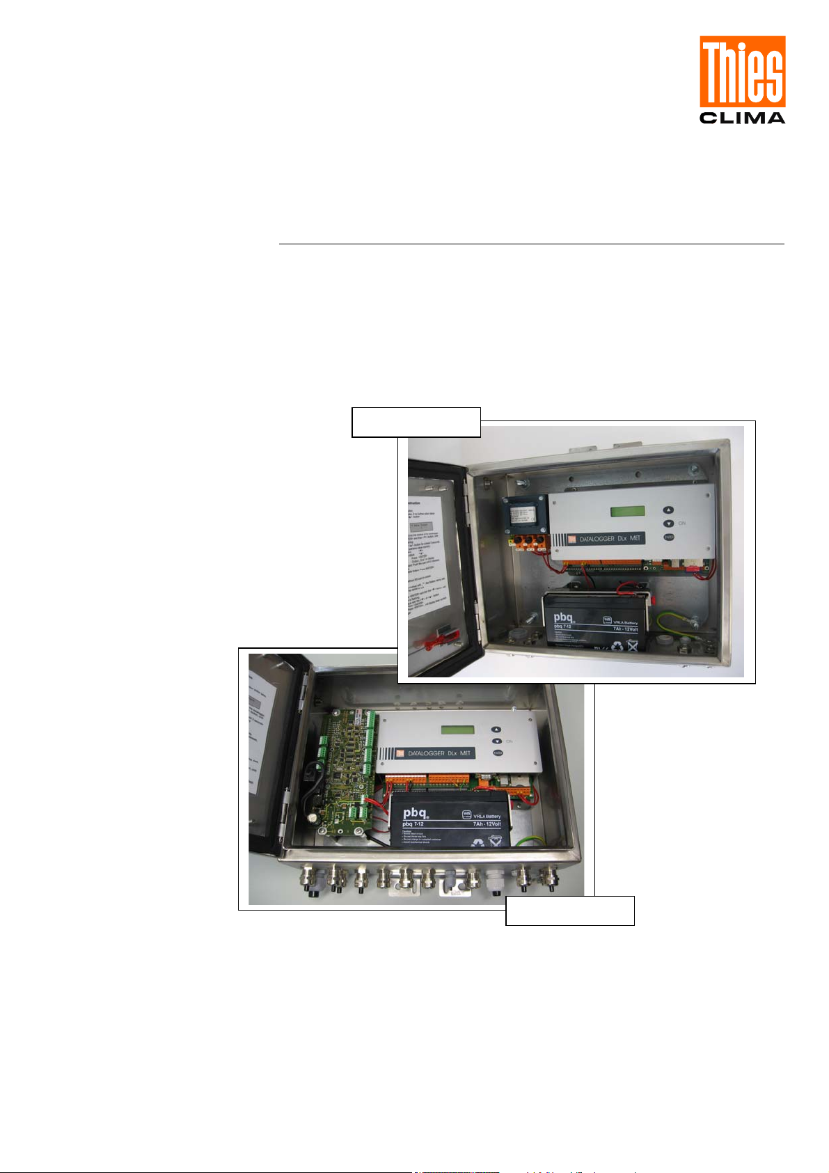
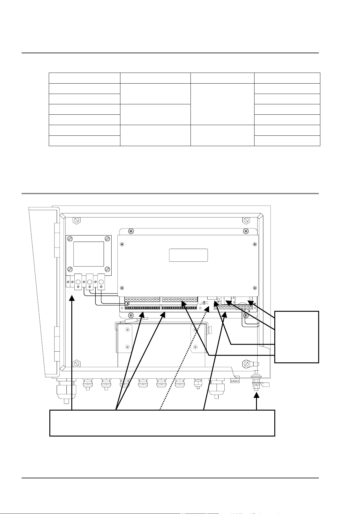
230VAC Clamps DCF77 Clamps Grounding
mains 1 … 56 (bottom side) 57 … 68 Earth
Figure 1: Connections
Page 5
DLx MET
Sensor-
Interface
Sensor - Int erface
Akku
Figure 2: Assembly with Sensor-Interface (9.1756.x0.100)
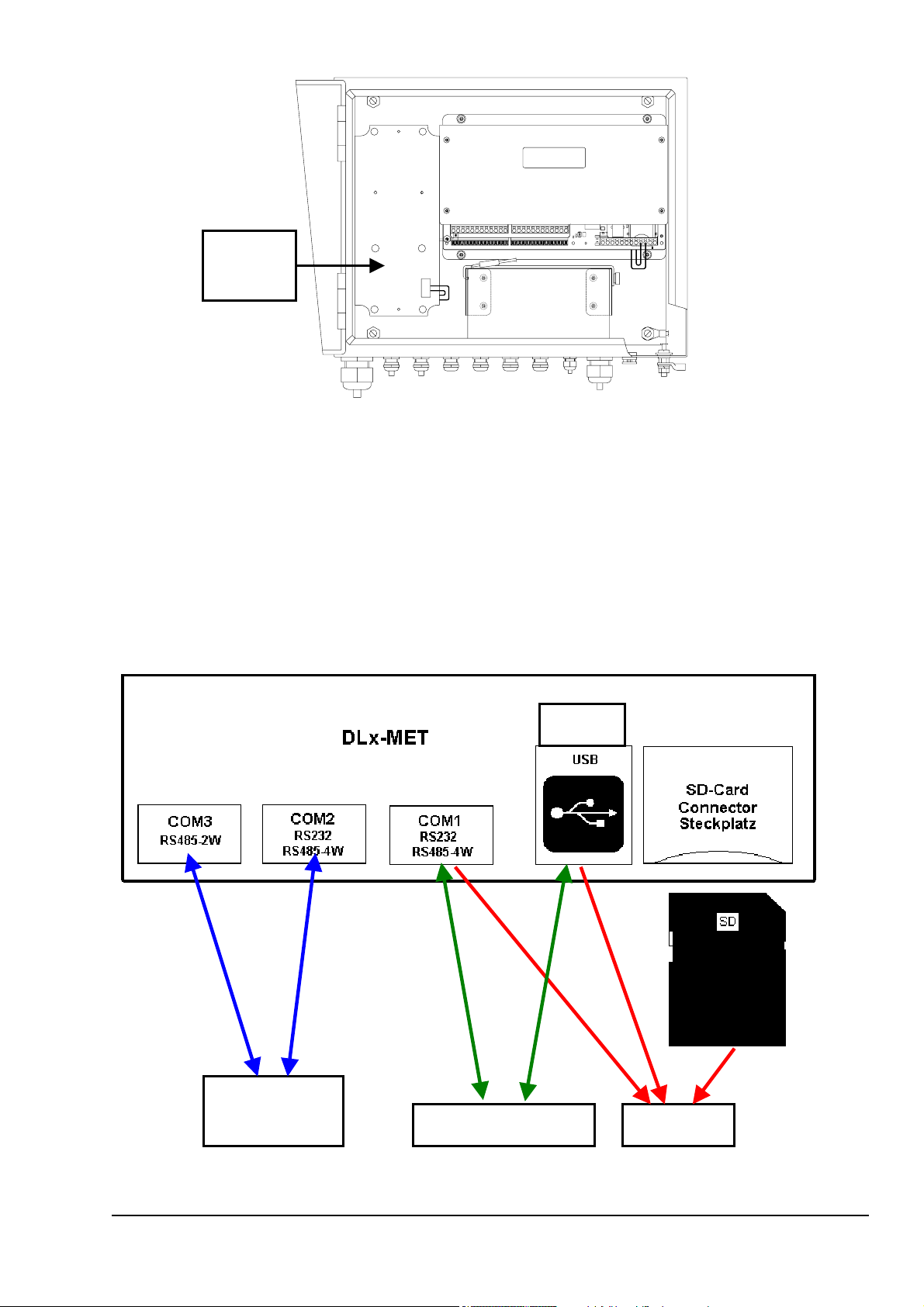
The datalogger DLx-MET is a complete measurement system serving for the acquisition and
storing of at minimum 10 meteorological parameters (e.g. temperature or radiation). Additionally in
the version 9.1756.x0.100 a so-called Sensor-Interface (SIF, see Figure 2) printed circuit board
with several measuring channels is connected to the serial interface COM2. Optional measuring of
other parameters or special sensors with serial output can be done by connecting the so-called
Sensor-Interface or a serial sensor to the serial interface COM2 or COM3 (RS485 2W, 2-Wire, halfduplex). The serial interfaces COM1 (used for commands and data output) and COM2 are
adjustable from operation mode RS232 to RS485-4W (4-Wire, full-duplex). See below Figure 3 for
a overview of all interfaces.
Device
IN: Sensor
Out: Telegram
IN/OUT: Commands
Out: Data
Figure 3: Interfaces of the datalogger
5 - 56 021579/06/09
Page 6
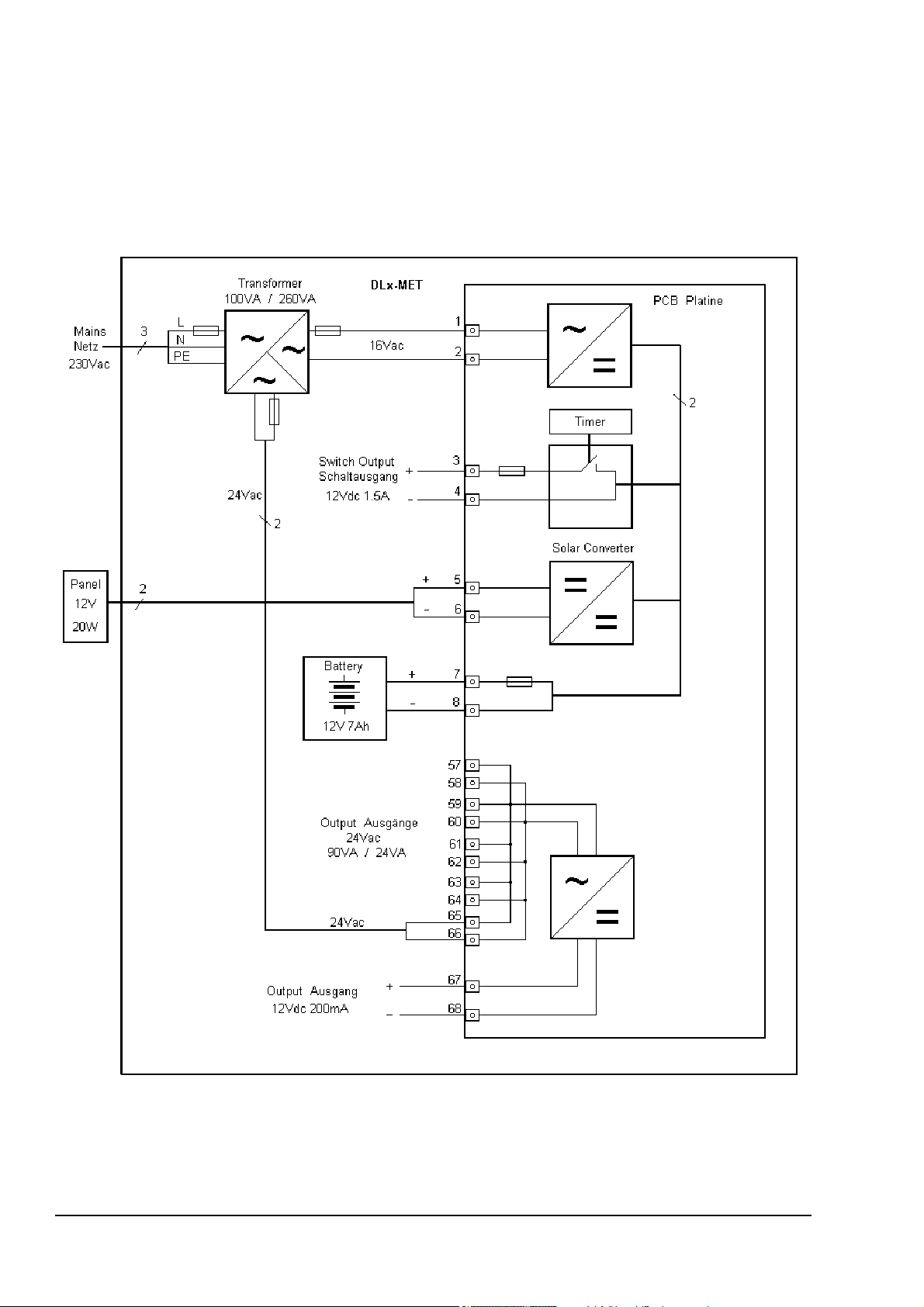
The instrument is battery-operated (12V), thus allowing it to be set up according to model and
sensor equipment at site without any mains supply for some hours or even days (applies not for
sensors measured by the Sensor-Interface). The exchangeable storage battery is situated in the
data logger case. With an optional 12V solar panel it is possible to load the battery.
Additionally a mains power supply (230VAC) can be used, which also supplies (24VAC) the heating
of sensors and the Sensor-Interface (apply only for 9.1756.x0.100). In this case the battery serves
for bridging in case of power failure. The following figure shows the supply possibilities.
Figure 4: Block diagram supply
In order to protect the accumulator against discharging the measurement of the sensors is
interrupted in case the voltage is below 10,5 V (thus the current consumption is minimized). Then,
6 - 56 021579/06/09
Page 7

the voltage is measured every 5 minutes; when it is higher than 11,0 V the normal measuring
routine is continued.
An integrated lithium battery buffers the contents of the data memory and the clock operation when
no other power supply is available. This means that the saved values and the time are not lost even
when there is no additional power supply.
The housing can be locked, is impermeable to jet-water (IP65), and is a very stable construction.
For shielding against electromagnetic fields the housing is made of stainless steel. In addition,
operation is guaranteed for temperatures ranging from – 30 °C to 60 °C.
The instrument can be easily operated either by means of three keys, via serial interface COM1 or
via USB. The three keys are referred to in the following as"<∆>", "<∇>"ON, and "<ENTER>" (see
Figure 5). A three-line, alphanumeric liquid crystal display (LCD) serves as indicating instrument.
ON
DATALOGGER DLx MET
EN TER
Figure 5: Front view
The scanning of the measuring values is selectable in the range from 1 second to 60 minutes. For
each of the 10 internal sensors the scanning, and further processing can be switched on or off
separately. The optional sensors connected to the Sensor-Interface are processed if the datalogger
receives a telegram over the serial interface COM2 (apply only for 9.1756.x0.100).
The measuring values are stored in a memory (CMOS-RAM) with a storing rate of 1 to 60 minutes
for mean values and 1 minute to 6 hours for extreme values. The memories are organized as socalled ring memory with a capacity of 1.4MB (mean) and 0.5MB (extreme) . If the capacity of the
ring memory is exhausted, the next step is to overwrite the oldest record. The reading-out of the
data can be carried out via the serial interface COM1, USB or via a Secure Digital Memory Card
(SD Card, see chap.5.2 for working types).
There is a so-called switch output available for the supply of an optional GSM-modem; by means of
this contact output the modem can be supplied at up to 6 selectable times a day.
It is possible to synchronize the internal time automatically by means of a separately connectable
DCF77-receiver module (reception range up to 2000km around Frankfurt(Main)/Germany).
For checking the sensors or the measuring inputs the datalogger can be turned into the
maintenance-mode. While this mode is active the measuring values of all the sensors cannot get
into the memory. I.e. values detected during the maintenance-mode are displayed, however, are
not taken into consideration for the calculation of mean- or extreme values.
7 - 56 021579/06/09
Page 8

2.1 MOUNTING
The datalogger is designed for wall-mounting or installation on a mast.
For proper protection against lightning strikes we strongly recommend to connect a preferably short
cable (≤1m) with a cross section greater than 6mm² between the case (see Figure 1, Grounding
Earth) and the mast (if used) with an earth terminal (e.g. grounding bound or main equipotential
bonding conductor). This connection is also necessary when mains (230VAC) is connected to the
datalogger.
It exists two case variants:
• 9.1756.10.x00x (case version A)
• 9.1756.00.x00x (case version B)
For the mast-installation of case version A seven different pipe clips with a diameter from 46 to
137mm are available. For mast-installation with case version B see chap. 2.1.2
8 - 56 021579/06/09
Page 9

2.1.1 Wall-mounting
For mounting on a wall or likewise use the 4 mounting holes:
• diameter 10mm, see
• (applies for 9.1756.00.x0x)
• diameter 8.4mm, see Figure 7 (applies for 9.1756.10.x0x)
Figure 6: Dimension illustration of the case version B (in mm)
9 - 56 021579/06/09
Page 10
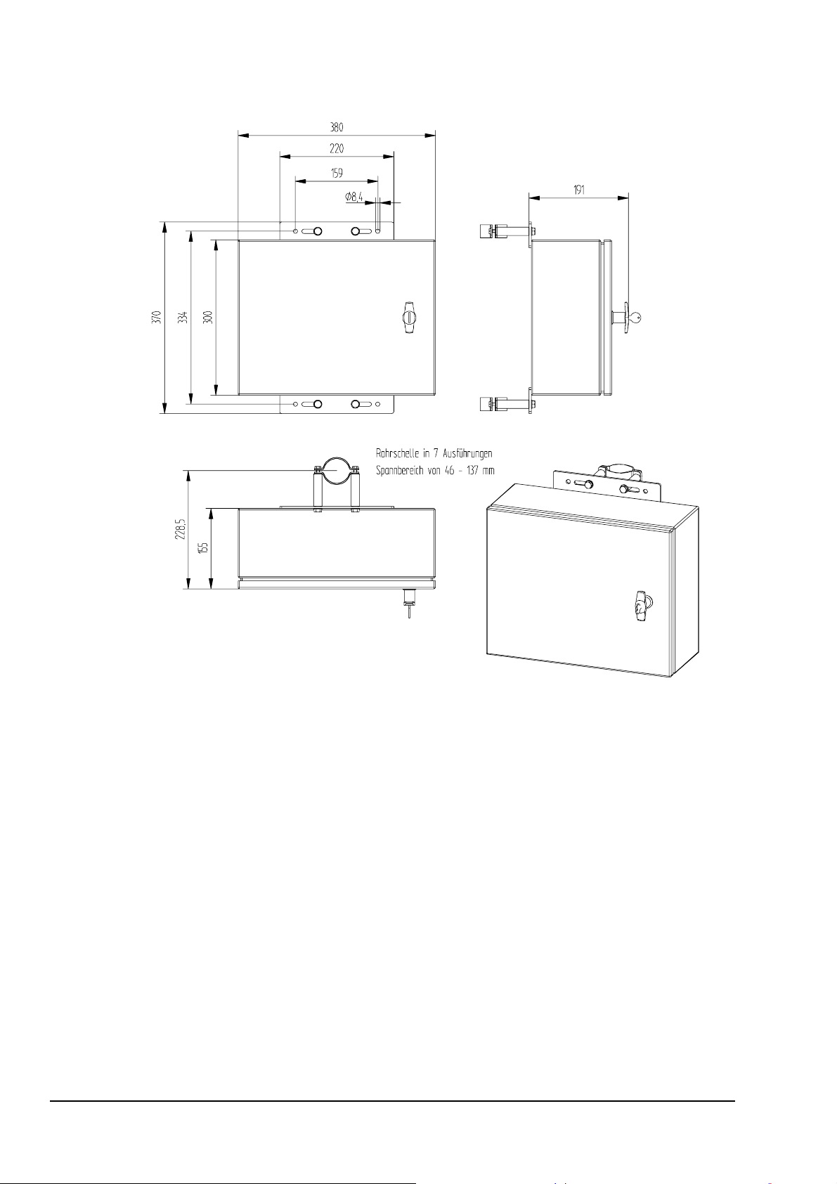
Figure 7: Dimension illustration of the case version A (in mm)
10 - 56 021579/06/09
Page 11
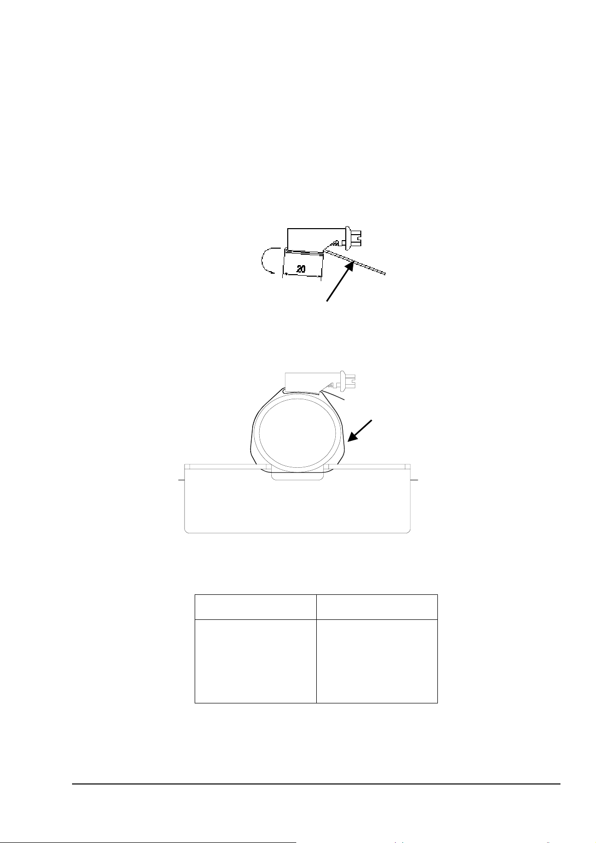
2.1.2 Mast-installation for case version B
The following instructions are only valid for case version B (9.1756.00.x0x).
1. Cut two piece in the requested length of the guy rope (1 meter) according to
table (see Table 1).
2. Insert the strap into the housing from the screw head side, and bend a projection of
20mm over the ridge (see Figure 8).
3. Put the free end of the prepared clamp around the mast and the mounting angle, and
screw it on (see Figure 9).
4. Two straps are provided for the datalogger.
Length of Guy Rope
Figure 8: Strap Housing
Mast Ø
Guy Rope
Mounting angle
Figure 9: Mast with guy rope
Mast Ø Length of Guy Rope
48 mm / 1.9 inch
60 mm / 2.4 inch
80 mm / 3.2 inch
90 mm / 3.5 inch
102 mm / 4 inch
250 mm / 10 inch
310 mm / 12.2 inch
370 mm / 14.6 inch
400 mm / 15.8 inch
440 mm / 17.3 inch
Table 1: Length of guy rope
11 - 56 021579/06/09
Page 12
2.1.3 Cable gland
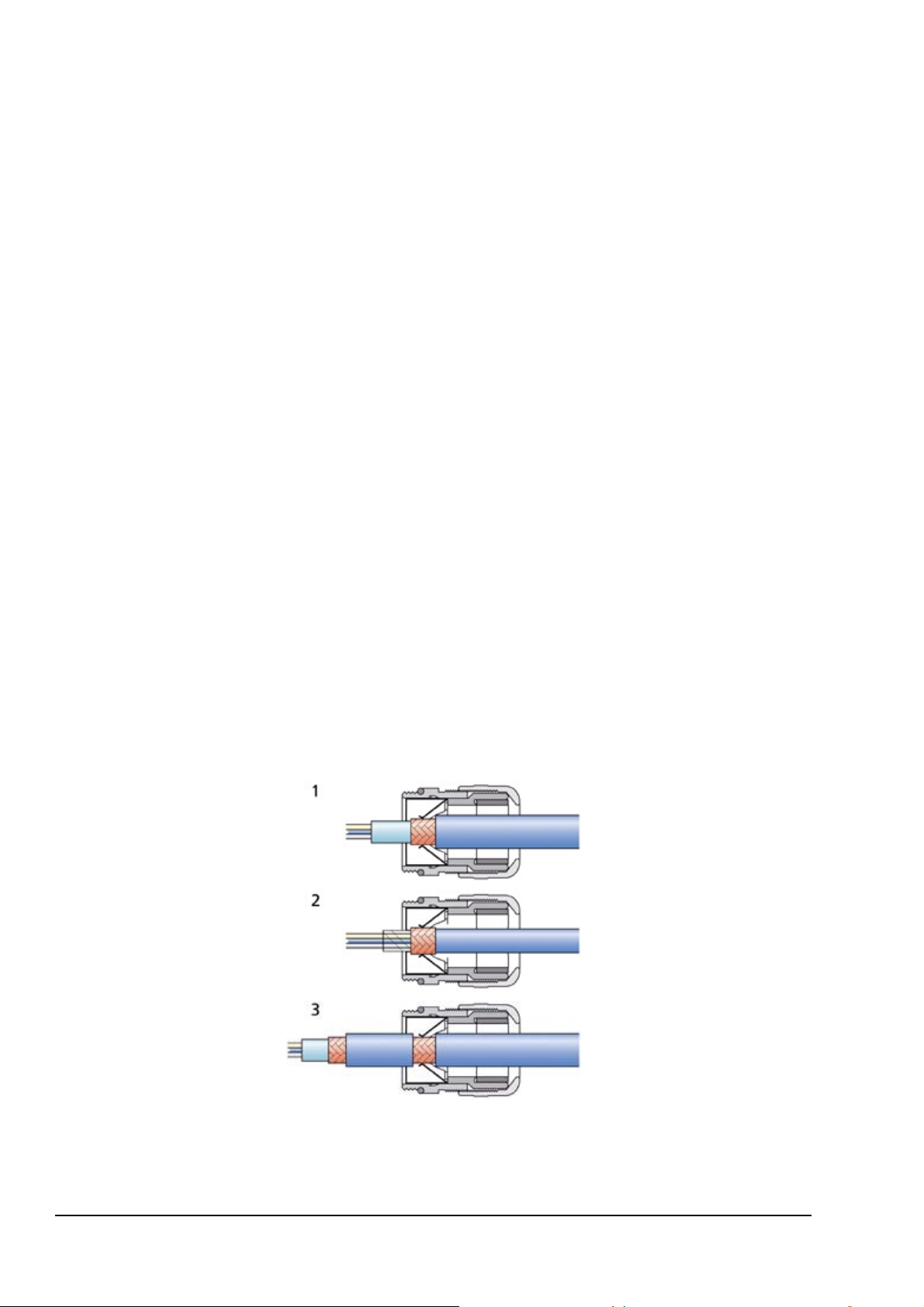
In order to carry out an EMC-compatible installation the cable screen (excepted the supply cable,
which is normally not shielded) is to be connected to the contact spring of the screwed cable gland
(see Figure 10) For wiring plan ref. to chap. 7.
1. With the Standard Contacting (see Figure 10-1)
- Strip back the outer sheath and screen (shielding)
- Make a round cut in the outer sheath approx. 15 mm along but do not remove the sheath
- Guide the cable through the cable gland
- Pull off the outer sheath
- Pull back the cable until the connection is made between the cable screen and contact spring
- Turn shut… and it is ready for use!
2. With thin Wires without an Inner Sheath (see
- Strip back the outer sheath
- Pull back the screen braid approx. 15-20mm over the outer sheath
- Insert the cables into the cable gland until the contact is made between the cable screen and
contact spring
- Turn shut ….and it is ready for use!
3. When Routing the Cable Screen to another Connection (see
- Expose the screen braid approx. 10 mm
-Guide the cable through the cable gland until the connection is made between the cable screen and
contact spring
- Turn shut…and it is ready for use!
Figure 10-2)
Figure 10-3)
Figure 10: Screen cable connection to the cable gland
12 - 56 021579/06/09
Page 13

2.1.4 Accumulator
The accumulator or battery is to be connected always. It is absolutely necessary to pay attention to
the specified polarity (red -> + ,black -> -)!
Remark:
When changing the accumulator, or with active power- or solar-supply please take care
that the red cable is not in contact with the housing parts (danger of short-cut)
During the installation please take care that all connections are voltage-free, and
that people and/or instruments are not endangered!
When replacing the accumulator with active power supply please take care that the red cable has
no contact with any part of the housing (danger of short-circuit).
A replacing or loading is necessary at the latest when the indicated accumulator voltage decreases
below 9.0V. However, a discharge of the accumulator below 11,0 V should be avoided, as no
considerable capacity is available any more. With operation below 10,5 V the life time of the
accumulator is reduced considerably! The new accumulator should be newly charged before
mounting, because, possibly, it might not have its maximum capacity due to self-discharge (approx.
3 % per month). The stored data are being secured during the replacement. Before disconnecting
the accumulator, the data should be saved. Without accumulator no measurements are being
carried out.
2.1.5 Mains supply
Safety Notes if using mains supply:
Attention! High Voltage. Mortal Danger!
The instrument must be mounted and wired only by qualified personnel, who
knows and observes the generalities of techniques, and applicable regulations
and norms.
Please keep in mind the local safety instructions.
Before carrying out any installation or service isolate unit from the mains supply!
in chapter 2.1.
When a Sensor-Interface(SIF, see Figure 2) board is installed (9.1756.x0.100), it is necessary to
swing open it to connect the 230V-power supply to the transformer or to check the fuses (see
Figure 1). When the both screws at the head of the SIF-board are removed you can turn the board.
When the 230V-power supply cable is installed, and connected, a red LED is active at the
datalogger between clamps 1 and 2 for the function control of the charging connection. In case this
LED does not light, the fuses of the 230VAC-input and the 16VAC-output of the transformer should
be checked.
13 - 56 021579/06/09
Page 14
Additionally a red LED lights up between clamp 67 and 68 for control the 24VAC supply (normally
used for heating of sensors). In case of malfunction check the fuses 230VAC and 24VAC.
Remark for 9.1756.x0.001:
The 26Vac output has no fuse, but a 135°C thermal trip switch which breaks the
primary supply.
2.1.6 Solar panel
Electric Connection:
The connection of the optional solar panel is to be carried out according the wiring plan
(see chap. 7). We recommend to earth the panel for protection against lightning strikes.
The integrated 12V solar regulator generates a temperature-controlled voltage for a
optimum load of the battery. The maximum power of the panel should not exceed 20W,
otherwise the regulator could be damaged. Due to the temperature-controlling the battery
should be always in the case of the datalogger.
Alignment:
• Direction: Always align the panel pointing to the sun at noon (south on the northern
hemisphere and vice versa) for an optimum performance. If necessary, refer to a compass.
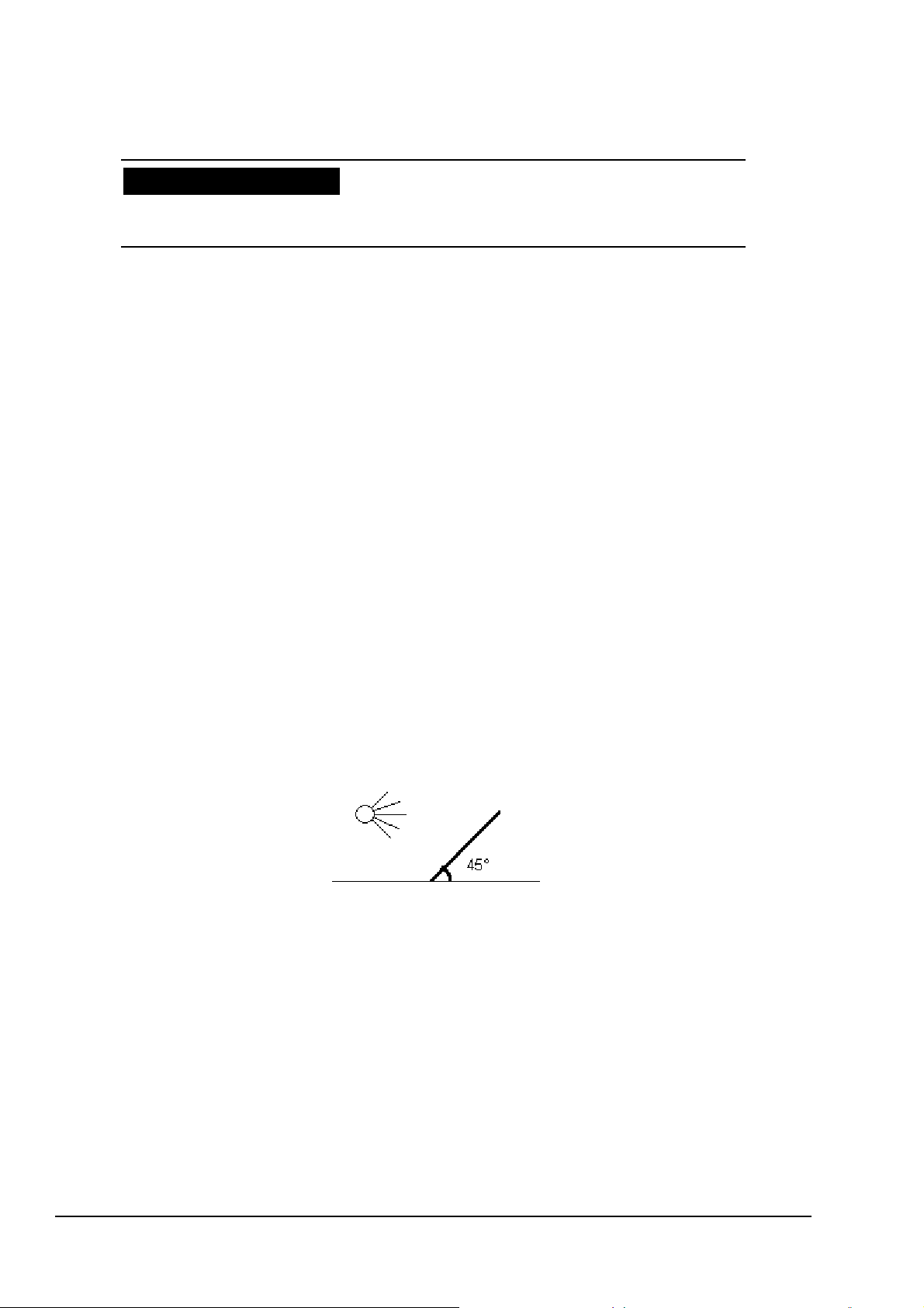
• Angle: The optimum tilt angle (angle between the horizontal plane and the solar panel, (see
Figure 11) depends on the latitude of the site. If the datalogger is to be used all the year
round, we recommend a tilt angle for optimum winter performance :
Tilt Angle = Latitude + 15° (apply not for Arctic / Antarctic region, maximum tilt angle 90°)
Example: Berlin(Germany) Latitude: 50.3° ---> Tilt Angle = 50.3° + 15° = 65.3°
Figure
11: Tilt angle for solar panel (here 45°)
• Nearby obstacles (trees, sensors etc.) should not block the sun at the panel.
Maintenance:
• Dirt, snow, leaves etc. on the panel reduces the amount of light and decreases the energy
yield. Therefore regularly clean the glass of the panel depending on the vicinity.
14 - 56 021579/06/09
Page 15

2.1.7 DCF-Active Antenna (9.1760.00.000)
For installation of the optional DCF-Active Antenna (9.1760.00.000) it is necessary to notice the
following:
Generally, please take care that the position of the antenna is optimal. It should be aligned
horizontally to, and across the direction of the transmitter (situated near Frankfurt/M., N 50° 01’, E
09° 00’). The antenna should have a minimum distance of 1m from sources of interference such as
power lines, and a 20cm-distance from metal obstacles. For other information on the alignment of
the antenna ref. to chap. 3.2.7 .
2.1.8 Remove Front Plate
For changing or checking of the jumpers for the digital input (ref. to chap. 2.1.9) or for the resistors
of the serial interfaces (ref. to chap. 2.1.10) the front plate (see Figure 5) has to be removed.
First remove the 4 recessed head screws of the front plate. Then move the plate carefully because
otherwise the ribbon cable for the three keys can be damaged.
Before you tighten the screws check the 3 keys of the front plate. When the keys are not working
anymore you had to insert the ribbon cable into the 4-pin connector of the printed circuit board.
15 - 56 021579/06/09
Page 16
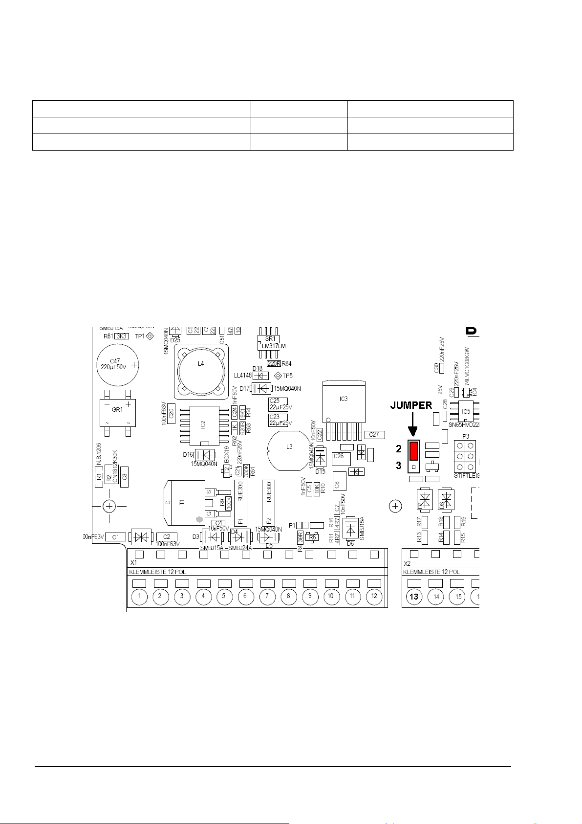
2.1.9 Setting Digital Input
The digital input „Event / Length of time” (Sensor 10) can be configured for two possibilities with the
Jumper P2:
Jumperposition P2 Logic * Inverse Level Miscellaneous
2 3.3V(5V TTL) No Pull-up Resistor 100kΩ to 3.3V
3 1V Yes ** Resistor > 1kΩ
Table 2: Jumper for digital input
* The corresponding switching levels are listed in the technical data (see chap. 6)
** Note that with jumper in position 3 the logic level is reversed by the electronic.
The jumper P2 is situated 2 cm above clamp 13 (see Figure 12). To change or check the position it
is necessary to remove the front plate (see Figure 5, ref. to chap. 2.1.8).
Figure 12: Jumper for Digital Input
16 - 56 021579/06/09
Page 17
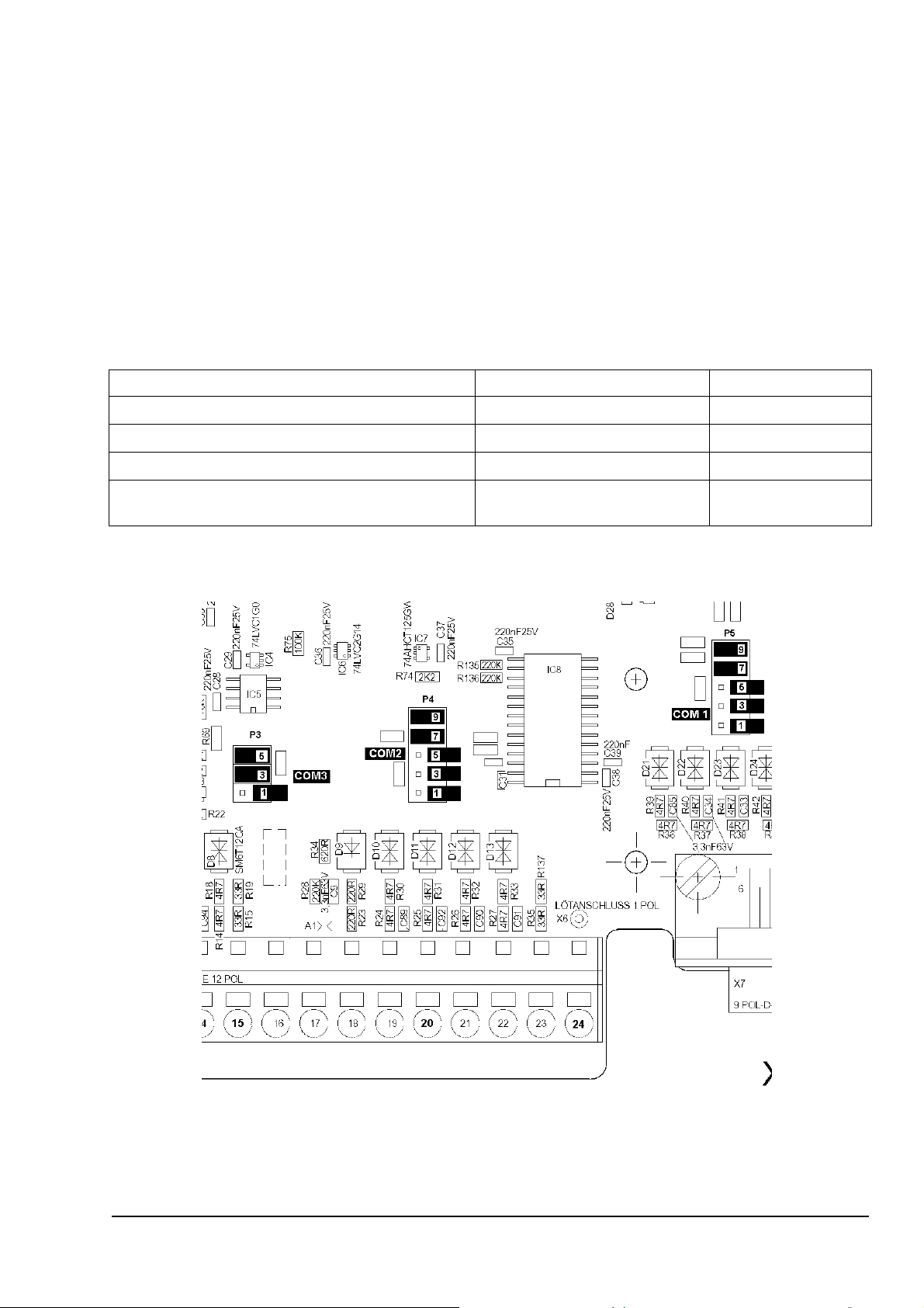
2.1.10 Setting Resistors Serial Interfaces
There are three multi-pin connectors for the serial interfaces when used in RS485 mode. To get the
lowest current consumption and no negative impacts when COM1(P5) or COM2(P4) are in the
RS232 mode all respective jumpers must be open. COM1 and COM2 are adjustable by firmware
between RS232 and RS485 (ref. to chap. 3.1 Baudrate setting). COM3 is always in the operation
mode RS485-2w (half-duplex).
To change or check the position of the jumpers it is necessary to remove the front plate (see
Figure 5, ref. to chap. 2.1.8). Figure 13 show the position of the multi-pin connectors:
COM1: 10-pin connecter P5 (above the 9 pin D-plug)
COM2: 10-pin connecter P4 (above clamp 20)
COM3: 6-pin connector P3 (above clamp 15)
Termination COM1(P5) COM2(P4) COM3(P3)
1000 Ω pull-down resistor
1000 Ω pull-up resistor
220 Ω termination resistor
T+/T- connected to R+/R- for 2 wire operation
(RS485-2w) (Remark: mode not available)
Table 3: Serial Port RS485 termination selection
J7-8 connected J3-4 connected
J9-10 connected J5-6 connected
J5-6 connected J1-2 connected
J1-2 and J3-4 connected --------------
Figure 13: Jumper for serial interfaces
17 - 56 021579/06/09
Page 18

3 OPERATION
When the accumulator is connected, the datalogger starts automatically with the so-called
Bootloader (uploads new Firmware), and re-initialises itself. The Bootloader waits 30 seconds and
start the actual Firmware automatically. After the first activation, time and date should be
controlled.
3.1 DISPLAY OPTIONS
The display is switched on through the button <∇> (press half a second at the most). The display
deactivates itself automatically, if – for 4 minutes – no button was pressed or no signal was sent or
received via the serial interfaces COM1 or USB. After the unit has been switched on the station
name appears on the display.
The character "*" as first character of the first line signifies for the user that it is possible to edit this
value or to get more information (ref. chapter 3.2). By pressing the <∇>-button you reach the next
indicated value, and get back respectively through button <∆>.
„M“ as first character of the second line with the sensor measuring values shows the maintenance
operation (see operation mode).
DLx Met
Bootloader V1.2
-
Remark:
The display can be read off up to a minimum temperature of –20°C . For
technology reasons, the time until the value appears on the display, is rather long
with low temperatures (approx. 10 seconds at –20 °C!).
18 - 56 021579/06/09
Page 19

SEQUENCE OF DISPLAY VALUES:
1. Station name
2. Date and time of datalogger
3. Data output
Internal sensor measured instantaneous values:
4. Sensor 1: Wind speed
5. Sensor 2: Wind direction
6. Sensor 3: Temperature 1
7. Sensor 4: rel. Humidity
8. Sensor 5: Precipitation
9. Sensor 6: Air pressure
10. Sensor 7: Radiation
11. Sensor 8: Temperature 2
12. Sensor 9: 20mA Input
13. Sensor 10: Event / Length of time
External sensor serial values, if configured:
14. Sensor 11 to ??
14. Sensor configuration
15. Sensor connection
16. Serial interfaces mode
17. Measuring cycle / storing cycle
18. Voltage of the accumulator / Status of power supply
19. DCF77 receiving control
20. DCF77 synchronisation
21. Switch output-timer
22. A/D-Converter State
23. State EEPROM
24. Baudrate COM1 / SD-Card
25. Baudrate COM2
26. Baudrate COM3
27. Operation Mode Normal / Maintenance
19 - 56 021579/06/09
Page 20

1. STATION NAME:
* Station: THIES
DLx(Met) V1.01a
USB:0 DE
The station name serves to distinguish the data from several stations. The name (here: "THIES")
can comprise up to 5 characters. On the readout, this name is output along with the data via the
serial interface. The instrument type(„DLx(Met)“) and the software version („V1.01a“) are mentioned
in the second line. The third line shows if a USB-connection is detected (USB:1) or not (USB:0) and
the “DE” indicate a German(Deutsch)/English version.
Serial command: “XXn” for input of the station name (ref. to chap.5.5)
Language:
When changing the station name (ref. to chap. 3.2.1) the second line turns to the language
selection for the display output („Language :English“ or „Sprache : Deutsch“); selecting between
both modes is possible, then.
2. DATE / TIME:
*Date: 01.01.08
Time: 13:00:00
Display of date and time of the logger.
Serial commands date: “DD”, “DT”, “DM”, “DJ” (ref. to chap.5.5)
Serial commands time: “ZZ”, “ZH”, “ZM”, “ZS” (ref. to chap.5.5)
3. DATA OUTPUT:
* Data Output
?
Starting the data output (ref. to chap. 5.1)
If there is no SD-Card in the slot of the datalogger, the output is carried out automatically via the
serial interface COM1.
Serial commands: “TS”,”ts”,”DS”,”ds”,”TE”,”te”,”DE”,”de”,”SS”,”GS”,”EE” (ref. to chap.5.5)
SENSOR MEASURED VALUES:
For display, all measuring values are detected, and updated every second.
General error message (exceeding of measuring range or sensor not connected) is the output of
„???.?“.
If a internal sensor is not configured (switched off) „---.-„ is output.
„M“ as first character of the second line with the sensor measuring values shows the maintenance
operation (see operation mode).
Serial commands: “mm” or “MM” (ref. to chap.5.5)
20 - 56 021579/06/09
Page 21

4. SENSOR 1 Wind speed:
* Windspeed:
NN.N m/s
Classic I:N
Line 2: Display of the instantaneously measured wind speed.
Line 3: Display and input type of sensor (Compact [4.3519.X], Classic [4.3303.X],
First Class [4.3350.X] and current flow test of sensor (I:0 -> off I:1 -> on)
Serial commands: “WV” and “WW” (ref. to chap.5.5)
Measuring range: 0.5 ... 65.0 m/s (Compact)
0.3 … 50.0 m/s (Classic)
0.3 … 75.0 m/s (First Class)
Resolution: 0.1 m/s
5. SENSOR 2 Wind direction:
* Winddirection:
NNN °
5-/8-Bit
Line 2: Display of the instantaneously measured wind direction.
Line 3: Display and input type of sensor (5-/8-Bit syn.ser. or 10-Bit syn.ser.)
Serial command: “WD” (ref. to chap.5.5)
5-Bit sensor: 8-Bit sensor: 10-Bit sensor:
Measuring range: 0 ... 349° 0 … 357° 0 … 359°
Resolution: <= 12° <= 3° 1°
6. SENSOR 3 Temperature 1:
Temperature 1:
NNN.N °C
Display of the instantaneously measured temperature1.
Measuring range: -40 ... 70 °C
Resolution: 0.1 °C
21 - 56 021579/06/09
Page 22

7. SENSOR 4 relative Humidity:
Rel.Humidity :
NNN.N %
Display of the instantaneously measured rel. Humidity.
Measuring range: 0.2 ... 100 % r.H. °C
Resolution: 0.1 % r.H.
8. SENSOR 5 Precipitation:
* Precipitation:
NNN.N mm
0.X I:N
Line 2: Display of the amount of precipitation which has fallen during the current day.
The sum of all precipitation since midnight, including the during the
maintenance mode.
Line 3: Display and input of the resolution of the sensor (0.1 -> 0.1mm, 0.2 ->
0.2mm) and current flow test of sensor (I:0 -> off I:1 -> on).
Serial commands: “NS” and “NT" (ref. to chap.5.5)
Measuring range: 0 ... 999.9 mm
Resolution: 0.1 / 0.2 mm
9. SENSOR 6 Air pressure:
* Air pressure :
NNNN.N hPa
Min:NNN Max:NNNNM
Line 2: Display of the instantaneously measured air pressure
Line 3: Display and input option for the measuring range of the air pressure sensor
Serial commands: “LM” and “LN" (ref. to chap.5.5)
Measuring range: (500-900)* ... (900-1100)* hPa
Resolution: 0.1 hPa
* Note: measuring range adjustable (see Line 3)
22 - 56 021579/06/09
Page 23

10. SENSOR 7 Radiation:
* Radiation :
NNNN.N W/sm
NN.NNNN uV/W
Line 2: Display of the instantaneously measured global radiation.
Line 3: Display and input of the radiation constant [µV/W]
Serial command: “SK1” (ref. to chap.5.5)
Measuring range: 0 ... >1428 W/m
Resolution : <1 W/m
2
2
11. SENSOR 8 Temperature 2:
Temperature 2:
NNN.N °C
Display of the instantaneously measured temperature 2.
Measuring range: -40 ... 70 °C
Resolution: 0.1 °C
12. SENSOR 9 20mA Input:
20mA Input:
NNN.N %
Display of the instantaneously measured 20mA Input.
Measuring range: 0 ... 100 %
Resolution: 0.1 %
23 - 56 021579/06/09
Page 24

13. SENSOR 10 Event / Length of time:
* Event/Length :
NNN.N
Event L:N
Line 2: Display of the instantaneously measured digital state input:
Mode Event: Level active (-> 1) / non-active (-> 0)
Mode Length: Length of time in minutes during the current day
Line 3: Display and input of the mode of the digital state input (Event or Length) and
the active logic (L:0 -> low active logic, L:1 -> high active logic)
Measuring range: 0,1 (Mode: Event) or 0 …. 9999 min (Mode : Length)
Resolution: 6 seconds (Mode : Length)
Serial command: “LS” and “LT” (ref. to chap.5.5)
Remark:
To setting up or check the logic level (3.3V or 1V) see chap. 2.1.8.
From here will displayed the instantaneous data of serial sensors if configured (e.g. Sensor-
interface or Sonic-windsensor). See following display 16 for adjustment and refer to chap. 3.2.5 for
additional information.
14. SENSOR CONFIGURATION:
x = “0” Sensor switched off
*Channel config:
xxxxx xxxxx
x = “1” Sensor switched on
Channels: 10+YY
YY= 00 to ??: Number of external channels
Sensor 1...10
Display of the configured internal measuring channel („1“→ switched on). Measuring channels
which are not configured („0“→ switched off) are marked by bars (for ex. „---.-“) in the display and in
the data output.
The first digit (from the left side) means the 1. measuring value of the sensor (wind speed) the last
one means sensor 10 (state/length).
For more information to change the sensor configuration ref. to chap. 3.2.3
Serial command: “KK” (ref. to chap.5.5)
24 - 56 021579/06/09
Page 25

15. SENSOR CONNECTION:
x = “+” Sensor connected
Sensor connec.:
xxxxx xxxxx
x = “-“ Sensor not connected
x = “0” Current flow test of sensor off
x = “X” Sensor not configured (see 14. sensor configuration)
Sensor 1…10 x = “?” Sensor not testable
This display shows whether a internal sensor is connected. A “-“ means that the datalogger not
detect the sensor, and the “+” stand for vice versa. A “+” means not mandatory that the sensor is
working respectively a good quality of the measurement.
16. SERIAL INTERFACES MODE:
* COM1: Command
COM2: Sonic R
COM3: SIF002
The display shows the settings of the three serial interfaces.
The COM1 interface is fix adjusted to operate the commands.
To get the lowest power consumption it is necessary to switch COM2 and COM3 off.
For more information to change the serial interface mode for COM2 and COM3 ref. to chap. 3.2.5
Serial command: “Cs” (ref. to chap.5.5)
17. MEASURING CYCLE / STORING CYCLE:
*Meas.Cyc. 1 sec
Memory C. 1 min
ExtremeC. 1 h
The display shows the adjustment of the measuring cycle (line 1), the mean (line 2) and the
extreme (line 3) value storing cycle. Refer to chap. 3.2.4 for additional explanation.
Setting options measuring cycle (applies only for the 10 internal sensors connected directly to the
datalogger):
1, 2, 3, 4, 5, 6, 10, 12, 15, 20, 30 seconds and
1, 2, 3, 4, 5, 6, 10, 12, 15, 20, 30, 60 minutes
Setting options mean storing cycle:
1, 2, 3, 4, 5, 6, 10, 12, 15, 20, 30 and 60 minutes
Setting options extreme storing cycle:
1, 2, 3, 4, 5, 6, 10, 12, 15, 20, 30 minutes and
1, 2, 3, 4, 6 hours
Serial commands: “MT”, “ST”, “ET” (ref. to chap.5.5)
25 - 56 021579/06/09
Page 26

18. VOLTAGE OF THE ACCUMULATOR / Status of Power Supply :
OK : voltage >11.5 V
Accumulator: OK
!!! voltage 10.6 ... 11.5 V
12.5 V
Low : voltage <10.5 V loading/replacing of the accumulator !
Mains AC: 1
Display of the measured voltage of the accumulator.
Line 3 displays the state of power supply (1: mains voltage present, 0: no mains voltage).
Remark:
Analogue measurements at a recorded voltage of below 9V are not accurate!
A discharge of the accumulator below 10,5 V should be avoided, as, firstly, no
considerable capacity is available any more, and secondly the life time of the
accumulator is reduced considerably ! Please replace or charge the accumulator,
if "!!!" is displayed. In order to protect the accumulator against further discharge
the query of the sensors is interrupted at a voltage of 10.5 V; thus the current
consumption is minimized . Then, the voltage is checked every 5 minutes; when it
is higher than 11,0 V the normal measuring routine is continued (ref. to chap.4).
19. DCF77 RECEIVING CONTROL:
DCF77 Test: ss nn
D:1.0s L:10 0
DCF77 Test: --
DCF-antenna on DCF-antenna off
For more information refer to chap.3.2.7.
20. DCF77 SYNCHRONISATION
*DCF: 1 !!.!!.!!
ffff n !!:!!:!!
!!.!!.!! !!:!! 0
*DCF77: 0
!!.!!.!! !!:!! 0
DCF-antenna on DCF-antenna off
For more information refer to chap. 3.2.8.
26 - 56 021579/06/09
Page 27

21. SWITCH OUTPUT TIMER:
*PROG-Timer: X
programmed
X= 1,2,3,4,5,6
*PROG-Timer:
deactivated
Display of the programmed timers for the connection of a consumer load (for ex. GSM-Modem,
refer to chap.3.2.6).
Serial command: “FS” (ref. to chap.5.5)
22. A/D-Converter State:
A/D: OK
State for service purposes only:
OK (A/D converter in order)
Err (A/D converter defect)
23. STATE EEPROM:
Estado EEPROM
Usuario:OK DL:OK
State of the EEPROM memory (parameter memory for user-settings and calibration values).
In case “OK” is not displayed here, the instrument might be defect.
24. BAUD RATE (COM1) / SD-Card:
No SD-Card in the slot
Display of the settings of COM1
Setting options:
300, 600, 1200, 2400, 4800,
9600, 19200, 38400, 57600
and 115200 Bd
8 data bits, no (none) parity,
1 stop bit, RS232 or RS485-4Wire
Serial commands: “CC1”, “CR1”
(ref. to chap.5.5)
* COM 1:Command
9600 Bd 8N1
RS232
SD-Card:
2 TM SD02G 3.2
xxxxxxxx 04.2008
SD-Card in the slot of the Datalogger
(Example, line 2 and 3 are specific for each SD-Card)
Display of the so-called “Card Identification
Register”(CID) of the SD-Card in the slot. The data of
the CID is necessary to differ the cards, since the label
on the card is normally of no relevance. Unfortunately
not all SD-Cards works with the datalogger (see chap.
5.2 for tested SD-Cards).
Line 2 : MID, OID, PNM, PRV of the CID
Line 3 : Product serial number (x) and manufacturing
date (month and year)
27 - 56 021579/06/09
Page 28

25. BAUD RATE (COM2)
* COM 2:SIF001
9600 Bd 8N1
RS232
Display of the settings of the serial interface COM2.
Setting options are the same like COM1 (see above).
In the first line the actual setting of the mode is displayed (here “SIF001”, see display 16: SERIAL
INTERFACES MODE for adjustment).
Serial commands: “CC2”,”CR2” (ref. to chap.5.5)
26. BAUD RATE (COM3)
* COM 3:Sonic
9600 Bd 8N1
485-2Wire
Display of the settings of the serial interface COM3.
Setting options are the same like COM1 (see above). except for fixed serial operation mode
(always RS485-2Wire).
Serial command: “CC3” (ref. to chap.5.5)
27. OPERATION MODE:
*Mode:
Normal
Display of the selected mode:
„Normal“: normal mode
„ Maintenance “: Maintenance mode (Measuring values are not stored in the memory)
Remark:
The maintenance mode is stopped automatically when the display is switched off!
28 - 56 021579/06/09
Page 29

3.2 CHANGING PARAMETERS
All display values which are output with a "*" to top left can be changed.
In order to be able to edit the displayed value, first simply press the <ENTER>-key and then the
<∇>-key. The value to be changed is then indicated by the flashing cursor. Now you can release
both keys. With the <∆> key the value can be raised, or decreased with the. <∇> key. If the set
value is o.k., simply press the <ENTER>-key again in order to leave the edit mode or to proceed to
the next changeable value.
3.2.1 STATION NAME
Station name identifies the measuring station. If several data loggers are in use, then each logger
should be given a different name. All letters and digits can be set as well as the underlining "_" and
the space key.
When the station name is changed in the second line the output language is displayed, and can be
selected through the arrow key.
3.2.2 DATE
If an invalid date is entered (for example.: 31.4.00), it is corrected automatically.
3.2.3 SENSOR CONFIGURATION
For changing the sensor configuration, it is necessary – after pressing the <ENTER>- and <∇> -key
at the same time – to proceed as follows:
The second line is cancelled, and an interrogation mark is output. Afterwards, press the <∇>- and
<∆> -key at the same time for 10 seconds. The „countdown“ is shown on the display. After the
„countdown“ has finished you can change the values as usual.
3.2.4 MEASUREMENT / STORE CYCLE
The measurement cycle indicates the time intervals at which the analogue sensor values are
measured by the data logger and the serial sensors (e.g. sensor-interface SIF) are requested. The
measurement cycle can be changed during operation without the preceding data being lost. All
digital inputs (wind speed, wind direction (every second) and precipitation) are continuously
measured independently from the measured value set.
There are 23 different measurement intervals available:
seconds: 1, 2, 3, 4, 5, 6, 10, 12, 15, 20, 30
minutes: 1, 2, 3, 4, 5, 6, 10, 12, 15, 20, 30, 60
The mean storing cycle indicates time interval for storing the measuring values. For this, the
measuring values are averaged, or accumulated.
The memory cycle is selectable in 12 steps.
Minutes : 1, 2, 3, 4, 5, 6, 10, 12, 15, 20, 30, 60
29 - 56 021579/06/09
Page 30

Example: meas. cycle 1 second
mean storing cycle 10 minutes
A mean value is calculated from 600 measuring values, and stored. The calculation of the mean
value is carried out as arithmetic mean with „normal“ sensors. Exceptions are the wind direction
(vectorial mean), and precipitation (formation of sums).
Remark:
When adjusting the measuring cycle the cycles of mean value memory and
extreme value possibly have to be corrected to an integral multiple!
The mean storing cycle influences the storing time period of the mean values (see following Table
4 for 9.1756.x0.000 without additional serial sensors (10 channels))
The extreme storing value cycle gives the time point when the extreme values are saved.
The extreme storing value cycle is selectable in 16 steps:
Minutes: 1, 2, 3, 4, 5, 6, 10, 12, 15, 20, 30
Hours: 1, 2, 3, 4, 6
The extreme value cycle influences the extreme value time period (see following Table 4 for 10
channels).
The storage period is the period of time until the old data are overwritten. The data logger has two
ring memories. Both time periods depend on the number of measured channels. Additionally the
time period of the mean value memory depends on the mean storing cycle set. The time period of
the extreme value memory depends similarly on the extreme storing value cycle set.
For other number of channels you can use the following formulas.
[ ]: means rounding down to integer
Calculation of quantity of mean ring memory dataset:
Quantity(Mean) = [32768 / (5 + 2 * Channels)] * 47
Calculation of quantity of extreme ring memory dataset:
Quantity(Extreme) = [32768 / (5 + 8 * Channels)] * 16
Example with 20 channels :
Quantity(Mean) = [32768 / (5 + 2 * 20)] * 47 = 34216 dataset
Quantity(Extreme) = [32768 / (5 + 8 * 20)] * 16 = 3168 dataset
That denote in this case the mean time period is 23.76 days (= 34216 / 1440) when the mean
storing cycle is 1 minute.
30 - 56 021579/06/09
Page 31

Mean storing cycle
Extreme storing cycle
1 min 28.8 2.7
2 min 57.6 5.4
3 min 86.4 8.1
4 min 115 10.8
5 min 144 13.5
6 min 172 16.2
10 min 288 27
12 min 345 32
15 min 432 (1.1 a) 40
20 min 576 (1.5 a) 54
30 min 864 (2.3 a) 81
1 h 1729 (4.7 a) 162
2 h --- 325
3 h --- 487 (1.2 a)
Mean value time period
[day]
Extreme value time period
[day]
4 h --- 650 (1.7 a)
6 h --- 975 (2.6 a)
Table 4: Summary over memory time periods with 10 channels
3.2.5 ADJUST SERIAL INTERFACES MODE
According to following Table 5 COM2 and COM3 can be switched off (lowest power consumption)
or adjusted for the input of serial sensors and output of telegrams. It is not possible to set both
serial interfaces to the same priority (e.g. COM2 to SIF001 and COM3 to SIF002). With this settings
the number of channels can be changed and in this case the ring memories (mean and extreme)
are new initialised.
To start the setting with the keys the procedure like sensor configuration (ref. to chap. 3.2.3) has to
be done.
Remarks:
Before change this settings save the measuring data of the logger!
In case of changing the number of channels the old mean and extreme data
is no more available!
The baudrate and mode (RS232 or RS485) parameters of a sensor must be same
as the corresponding serial port of the datalogger (COM2 or COM3).
31 - 56 021579/06/09
Page 32

If more than one sensor is selected, the order of the sensor values in the display and memories is
done according the priority in the following table. The sensor with the lowest priority value is output
first. E.g. when Sonic (priority 1) and SIF(priority 3) are set, the values from the Sonic are given out
before the data of the SIF.
The index of the table below shows the values needed for programming via the serial interface
(command “Cs”, ref. to chap.5.5).
To get the lowest power consumption it is necessary to switch COM2 and COM3 off.
Index Display text Priority Channel Function
0 Off/Aus - - COM not used (lowest power consumption)
1 Sonic R 1 3
THIES Windsensor SONIC (ref. to chap. 3.2.5.1)
2 LPM/LNM A 2 6 Soon available
3 T-WindLED - -
4 T-Online - -
6 T-Online 2 - -
7 SIF001 3 6
8 SIF002 3 9
Table 5: Serial Interface Modes
Soon available
Soon available
Soon available
THIES Sensor Interface 001 (ref. to chap. 3.2.5.2)
THIES Sensor Interface 002 (ref. to chap. 3.2.5.2)
3.2.5.1 SENSOR THIES SONIC
The THIES SONIC sensors (“Ultrasonic Anemometer 2D” with software version 3.09 and higher)
are connectable to the datalogger on COM2 (RS485-4Wire, full-duplex) or COM3 (RS485-2Wire,
half-duplex), if the following settings are done:
• ID = 0
• Baudrate 9600Bd 8N1 (BR = 5, command “00BR00005”)
• automatic output off (TT = 0)
• only for full-duplex : DM = 2 (or 1)
• only for half-duplex: DM = 0 and RD = 20
Preset THIES SONIC versions working with this datalogger:
• Full-duplex (COM2): 4.3820.00.300, 4.3820.30.300
• Half-duplex(COM3): 4.3820.01.301, 4.3820.31.301
The data of the SONIC are requested with the command “00TR00002” (VDT-telegram: Wind
speed, wind direction, acoustic-virtual temperature). With the command “SO2”(ref. to chap. 5.5) it
is possible to send a command to the sensor.
32 - 56 021579/06/09
Page 33

3.2.5.2 SENSOR-INTERFACE SIF
In the case of model 9.1756.X0.100 is a so-called sensor-interface SIF build in and is connected to
COM2 (9600Bd 8N1, RS232 mode) of the datalogger. Available are different SIF which separate
between number and type of channels. The data are requested with the command “mm”. The
command “SI2” (ref. to chap. 5.5) can be used to send a command to the SIF.
SIF001, 6 channels: Radiation 2 + 3, Direct-radiation 1 + 2, Temperature 3 + 4
SIF002, 9 channels: 10V-input, 1V-Input 1 + 2, 20mA-Input 2 + 3 + 4, Temperature 3 + 4 + 5
3.2.6 SWITCH OUTPUT TIMER
The timer activates up to 6 daily time slots for an externally connected GSM-modem.
By setting small time slots (for ex. 5 min) the average current consumption of the modem per day
(operating current approx. 200 mA) can be kept down.
During a data transmission via a timer-controlled modem, the remaining power-on-time is fixed on 5
min, thus a re-logging-in in case of a failure is guaranteed within this period.
In the edit mode all timers can be set in turn .
Selectable are the daily starting time, and the minimum power-on-period.
TIMERx: HH:MM
ONLINE: NN min
x = 1,2,3,4,5,6
„HH:MM“ indicates the starting time of the respective timer slot in the format hour:min.
The power-on-period is selectable in minute-increments from 5 to 31. When the power-on-time is
set to 0, the respective timer is deactivated.
Remark:
Only timer 1 is activated even if the discharge-protection for the accumulator is
active (voltage < 10.5V).
33 - 56 021579/06/09
Page 34

3.2.7 DCF77 RECEIVING CONTROL
DCF77 Test: ss nn
D:1.0s L:10 0
DCF77 Test: --
DCF-antenna on DCF-antenna off
This display serves for controlling and setting of the DCF77-antennna.
„ss“: indicates the seconds (0-60, with overflow „??“), after the minute mark has been
identified
„nn“: cycle counter (0-99) of the received second marks.
„D:D.Ds“: time difference of the second marks in seconds (ideal: 1.0s, except for the second
60 (minute mark): 2.0s)
„L:NN B“: length of the second marks in 10ms(NN).
B indicates the binary decoding (L= 6..13[10ms] -> „0“, L= 16...23[10ms] -> „1“,
other lengths are output with “?”)
After this output has been activated, the following values appear for example:
DCF77 Test: ??
2 D:1.0s L:19 1
The minute mark has not yet been identified („??“). The 2. second mark received has a length of
190 (19*10)ms.
The length of the second mark (optimal: L=10 resp. L=20, the length is shorter with weak reception)
is well suited for the optimal alignment of the antenna.
After the minute mark has been recognized (D:2.0s und L: 7...13[10ms]) „ss“ is output and is raised
every second up to a maximum of 60. When the reception is correct, “ss” and “nn” run almost
synchronously. A difference of more than 1 means, that error pulses or not enough pulses have
been received; thus a decoding of the DCF77 time information is impossible.
DCF77 Test: 32
32 D:1.0s L:08 0
Remark:
If the reception is very weak in the daytime, the antenna should be aligned at
night (broader reach). Never try to align the antenna during sunrise or sunset (site
of transmitter and receiver/datalogger) !
Possibly, there are several alignments (neither horizontal!) allowing a reception
(reflections).
The transmitter can be inactive for several hours (thunderstorm close to the
sender).
34 - 56 021579/06/09
Page 35

3.2.8 DCF77 SYNCHRONIZATION
*DCF: 1 !!.!!.!!
ffff n !!:!!:!!
!!.!!.!! !!:!! 0
*DCF77: 0
!!.!!.!! !!:!! 0
DCF-antenna on DCF-antenna off
This display serves for switching on and off the DCF-antenna, indicates the last time of
synchronization (third line) and the manual start of synchronization.
When the DCF-antenna is active, it tries to receive a time telegram at night from 01:30 h (max. 10
minutes) because of the better reception. This time telegram is sent during standard time as CET
(“Central European Time”, CET=UTC+1h), and during daylight saving time as CEST (“Central
European Summer Time”, CEST=UTC+2h). This time telegram is converted in UTC, and the
internal clock is synchronized.
In the edit mode the antenna can be activated and deactivated. Additionally in the third line the last
synchronised DCF77-Time is given out:
*DCF: 1
s = 0 CET/standard time
30.04.09 03:33 s
s = 1 CEST/daylight saving time
With active DCF-antenna, and sufficient reception, when you wait approx. 2 minutes or longer, the
DCF time telegram is displayed, and the internal clock is synchronized (provided that no error
occurs).
Example: Reception of a time telegram (year not yet received)
ffff = Error display in the hexadecimal (0 means “no error”)
*DCF: 1 30.04.!!
ffff n 09:06:52
n = 0...9 display of the received second pulses
When the minute mark has been received, the seconds are set to zero
Second 28: reception minute
Second 35: reception hour
Second 41: reception day
Second 49: reception month
Second 57: reception year
35 - 56 021579/06/09
Page 36

4 MEASURING VALUE ACQUISITION
For reasons of current consumption the display, and other control parts are switched off in case
that for 4 minutes no button has been pressed, or no data communication over COM1 or USB has
been proceeded.
When the display is on (display mode) all configured internal channels are scanned every second.
In the pure measuring mode (display off) the configured analogue measuring channels are
measured, depending on the set measuring cycle ( 1 second to 1 hour). The digital measuring
channels are measured every second.
The following figures will make clear the process of the measuring value acquisition:
Every 5 minutes:
measure supply
voltage
ON
Measuring mode
(display off)
Discharge protection ?
OFF
Depending on measuring cycle:
measure instantaneous value
Depending on storing cyle:
Calculate and store mean-, and extreme
values
36 - 56 021579/06/09
Voltage >
11.0V?
Yes
Discharge protection
OFF
Figure 14: Flow diagram in the measuring mode (display off)
Voltage <
10.5V?
Yes
Discharge protection
ON
Page 37

Display mode
(display on)
Measure instantaneous values
Every second:
Maintenance ?
No
Depending on storing cycle:
Calculate and store mean- and
extreme values
Figure 15: Flow diagram in the display mode (display on)
37 - 56 021579/06/09
Page 38

5 DATA OUTPUT
On principle, there are three interfaces existing at the datalogger for the data output:
serial interface COM1 (RS232/RS485)
serial interface USB
SD-Card (Secure Digital memory Card)
With the serial interfaces COM1 and USB it is possible to query the data of the datalogger via a
cable from another computer. Via the both serial interfaces it is possible to wake-up the datalogger
(Display on), with sending a byte, therefore it is not necessary to wake-up with the "<∇>"ON -key.
The serial data output can be carried out manually (only COM1) or by remote-control (ref. to chap.
5.5 for commands).
For the reading out of data you can use a usual terminal program (e.g. “Terminal” of WINDOWS,
general settings for COM1see following Table 6). For communication via USB also a terminal
program can be used, but here a configuration is not necessary (ref. to chap. 5.4)
The serially transmitted data are output as ASCII-files (clear text). Thus, you are in a position, to
see your data records with word processors, as well, to process them and to print them out.
Herewith, you are also in a position to follow up your data via the ASCII-interface with standardsoftware such as spread sheet, data bases etc.
Furthermore it is possible to upload a firmware over COM1.
The data written on the SD-Card are saved in the same ASCII form as over the serial interfaces.
Baud / Bits per second just like baudrate COM1 of the
datalogger
Databits 8
Parity none
Stopbit 1
Flow control / Handshaking none
Table 6: Terminal Program Configuration COM1
38 - 56 021579/06/09
Page 39

5.1 DATA OUTPUT MANUALLY
With the manually data output the complete ring memory (mean or extreme) will be given out on
serial port COM1 or on a SD-Card (ref. to chap. 5.2).
SD-Card:
1. Set the display to
* Data Output
?
2. Push and snap in the SD-Card into the slot of the datalogger.
3. First press <ENTER> and then <▼> -button, until
the cursor is flashing.
4. Press <▼> - or <▲> -button for at least 3 seconds.
5. Select mean or extreme value memory:
X: “M” Mean value: <▼>
X: “E” Extreme value: <▲>
* Data Output
X-data
6. Start output: Press <ENTER>
7. To cancel or end data output: Press <ENTER>
8. Finish of output: Output „ END “ on display (line 2)
Y: “M” (mean) or “E” (extreme)
ooo: “SD” or “COM1”
* Data Output
Y ooo: NNNNN END
sssssY00.TXT
NNNNN: number of scanned data
records
Line 3: Filename on SD-Card (ssss: station name)
9. Remove the card when the output is ready:
Push the Card until it releases, then pull it out (so called e
jector type
Push-In/Push- Out).
39 - 56 021579/06/09
Page 40

Serial (COM1):
As above but without SD-card in socket (number 2 and 9 do not apply).
Additional information’s for the using of SD-Cards:
The data files are stored on the SD-Card in the following tree structure:
D:\ Root-Directory (here drive D)
sssss\ Subdirectory (Station name)
sssssMnn.TXT Mean memory files (nn: 00..99)
sssssEnn.TXT Extreme memory files (nn: 00..99)
Example station “MET23”: “D:\MET23\MET23M00.TXT”
The data on a CD-Card is always written into the “00”-file. If a “00”-file is present in the subdirectory
the datalogger tries to append only the new data. Whenever the “00”-file is greater then ten million
bytes, the “00”-file is renamed to a not existing “01”- till “99”-file. Unless the renaming is possible,
the output of the data will be breaked.
Remarks:
The datalogger do not delete any data on the SD-Card.
The user is responsible to use a SD-Card with enough free memory and the
deleting of the old “01”- to “99”-files.
The write-protect tab of the SD-Card is not used by the datalogger.
We strongly recommend to backup the data on alternative media.
Do not eject the card while writing the data. Press the “ENTER”-Key for breaking
the output.
Liability is excluded for loss of data.
Refer to chapter 5.2 for recommended SD-Cards.
40 - 56 021579/06/09
Page 41

5.2 RECOMMENDATIONS ON SD-CARD
To display the so-called “Card Identification Register”(CID: MID, OID, PNM, PRV) of the SD-Card
refer to chap. 3.1 (Baudrate COM1 / SD-Card). The data of the CID is necessary to differ the
cards, since the label on the card is normally of no relevance.
List of tested SD-Cards (maximum size 2GB, sorted by manufacturer ID) see following table.
MID: Manufacturer ID OID: OEM/Application ID
PNM: Product name PRV: Product version
Work with
Datalogger
Platinum
Label Size Manufacturer MID OID PNM PRV
2GB Panasonic 1 __ _____ 0.0 YES
Kingston 512MB SD512 1.5 YES
Kingston
AgfaPhoto
2GB
Toshiba 2 TM
SD02G
2.8
3.2
YES
3.8
512MB SD512
SanDisk
1GB SD01G
2GB
SanDisk 3 SD
SD02G
8.0 no
Platinum 1GB ??? 27 SM UD___ 1.0 YES
PNY Technologies
extreme memory
1GB ??? 39 PH SD01G 2.0
YES
AgfaPhoto
extreme memory 1GB ??? 62 H- FLASH 0.0 YES
extreme memory 2GB ??? 136 __ NCARD 1.0 YES
Table 7: Tested SD-Cards
Remarks on SD-Card:
Use only positive tested SD-Cards. Refer to the above list. Not all cards are
compatible with the datalogger.
The SD-Cards must be preformatted with the standard “FAT16”-format (deliverer
condition of the SD-Card).
41 - 56 021579/06/09
Page 42

5.3 CONNECTING RS232 CABLE OF COM1
The serial interface COM1 in RS232 mode is designed as “three-wire”-connection. The
transmission line (TxD) and the receiving line (RxD) are to be crossed in the cable.
PC/TERMINAL
cable
Sub-D25 (25 pins)
TxD 2 2 RxD
RxD 3 3 TxD
Ground 7 5 Ground
Both sides Sub-D9 (9 pins)
RxD 2 2 RxD
TxD 3 3 TxD
Ground 5 5 Ground
Table 8: Connections COM1 for RS232
Datalogger DLx
Sub- D9
5.4 USB
For the communication via USB it is required to have a VCP (Virtual COM Port) driver on the used
PC. Virtual COM port drivers cause the USB device to appear as an additional COM port available
to the PC. Application software can access the USB device in the same way as it would access a
standard COM port.
The driver is available from FTDI (FT245R): http://www.ftdichip.com/Drivers
In addition installation guides for several operating systems can be downloaded from there.
The USB cable between PC and datalogger is a common so-called AB-plug-cable.
42 - 56 021579/06/09
Page 43

5.5 FORMAT OF THE COMMANDS
The following commands operate with the serial interfaces COM1 and USB of the datalogger.
The commands are 4 to 12 bytes long:
STX ? ? ? ? ? ? ? ? ? ? ETX
Begin of command:
0x02(Hex) / Ctrl-B
Command:
2 ... 10 Bytes
LIST OF THE COMMANDS:
"HH" Help: indicates the list of entering commands
“PD“ Turn Datalogger into “power down” (display off, Measuring-Mode)
“RS” Reset of the Datalogger. Start of Bootloader
„CC1“<0..9>
“CC2”<0..9>
“CC3”<0..9>
„CR“<n><0,1> Set operation mode COM n(n = 1,2) 0:RS232 1:RS485-4w
“Cs000 ”aaa’ ‘bbb Configure sensor or telegram for COM2 and COM3
„MT“<01s,02s,03s,04s,05s,06s,10
s,12s,15s,20s,30s,01m,02m,03m,
04m,05m,06m,10m,12m,15m,20
m,30m,60m>
„ST“<01m,02m,03m,04m,05m,06
m,10m,12m,15m,20m,30m,60m>
„ET“<01m,02m,03m,04m,05m,06
m,10m,12m,15m,20m,30m,01h,0
2h,03h,04h,06h>
„SS“ Output of all stored mean values
„GS“ Complete mean memory:
“EE” Output of all stored extreme values
"TS"<DdMoYy>
“ts”<d><m><y>
„DS“<DdMoYyHhMi>
“ds”<d><m><y><h><m>
"TE"<DdMoYy>
“te”<d><m><y>
Set baud rate COM1
Set baud rate COM2 0:300Bd … 5:9600Bd … 9:115200Bd
Set baud rate COM3
aaa:COM2 bbb:COM3 values according to index in Table 5
Example: STX “Cs000 008 001”ETX
COM2: 8 (-> SIF002) COM3: 1 (-> SONIC)
Ref. to chap.3.2.5 for additional remarks. Old data can be deleted!
Set measuring cycle in seconds or minutes
Set mean storing cycle in minutes
Set extreme storing cycle in minutes and hours
Reasonable only, when the logger has re-initialised itself, in order to
save data which have not been overwritten
Stored mean data of one day
Description of parameters: ref. to chap. 5.5.1
Output of stored mean data from a specific time
Description of parameters: ref. to chap. 5.5.1
Stored extreme data of one day
Description of parameters: ref. to chap. 5.5.1
End of command:
0x03(Hex) / Ctrl-C
43 - 56 021579/06/09
Page 44

„DE“<DdMoYyHhMi>
“de” ”<d><m><y><h><m>
Output of stored extreme data from a specific time
Description of parameters: refer to chap. 5.5.1
"EP" Output of EEPROM-data (parameter memory) for service purposes
Logger status:
Output station name, date and time , state of the AD-transducer,
"LL"
sensor configuration, measuring and storing rates, voltage of the
accumulator, state of power supply, radiation constant, EEPROMstatus, operation mode, contact output-Timer, last DCFsynchronisation time and appropriate logger time
"MM" Instant. measuring values: output with sensor identification (multiline)
"mm" Instantaneous measuring values: output as single-line data record
(sequence as in the display output)
"DD" Output Logger-date
"DT"<1..31>
Entering day: Setting of day for the logger-clock (*)
Response: entered day, logger date
"DM"<1..12>
Entering month: setting of month for the logger-clock (*)
Response: entered month, logger date
"DJ"<0..99>
Entering year: setting of year for logger-clock (*)
Response: entered year, logger date
"ZZ" output logger-time
"ZH"<0..23>
Entering hour: entering of hour for the logger-clock (*)
Response: entered hour, logger-time
"ZM" <0..59>
Entering minute: entering of minute for the logger-clock (*).
The second is set to zero.
Response: entered minute, logger-time
„ZS“ <0..59>
Entering second: setting of second for the logger-clock. (*)
Response: entered second, logger time
"XX" Output of the station name, instrument type, and software-version.
„XXn“<AAAAA> Entering station name
„LM“<500..900> Enter of the lower measuring range in hPa of the air pressure sensor
„LN“<500..900> Enter of the higher measuring range in hPa of the air pressure sensor
“WV”<0..3>
Wind speed sensor type
(0:COMx, 1:Compact, 2:Classic, 3:FirstClass)
“WW”<0,1> Wind speed sensor current flow test (0:Off)
“WD”<0..2> Wind direction sensor type (0:COMx, 1:5-/8-Bit, 2:10-Bit)
„NS“<1,2> Precipitation sensor type resolution (0.1mm / 0.2mm)
“NT“<0,1> Precipitation sensor current flow test (0:Off)
„LS“<0,1> Digital input mode: Event(0) or Length(1)
„LT“<0,1> Digital input logic: active logic low (0) or active logic high (1)
„SK“<n>’ ’<NN.NNNN>
Enter radiation constant n (n=1…5)
Example: STX „SK1 12.42“ ETX (set constant 1 to 12.42)
Entering sensor configuration of a internal sensor
“KK“<01..10>’ ’<0,1>
<01..10> sensor number
<0,1> 0 -> switch off 1 -> switch on
Example: STX “KK02 1“ ETX (switch on sensor 2)
“FF“ Output of all switch-output timers
“FS“<1..6><HH><MM><LL> Setting of a switch output-timer: <1..6> timer number,
<HH> starting hour, <MM> starting minute, <LL> power-on time in
minutes
Ex.: STX “FS2083005“ ETX (timer 2, start at 08:30 h, time: 5
minutes)
44 - 56 021579/06/09
Page 45

“SI2”<AAAAAAA> Transparent Gateway / Bridge command to Sensor-Interface SIF
(9.1756.x0.100)
The command <AAAAAAA> (up to 7 signs) is send to COM2 or COM3
and the answer is given back. STX and ETX is added automatically.
Operation only if SIF configured.
Example: STX “SI2HH” ETX -> Help (HH) from SensorInterface
“SO2”<AAAAAAAAA> Transparent Gateway / Bridge command to SONIC. Works only for
commands with a single-line answer and if SONIC is configured.
The command <AAAAAAAAA> (up to 9 signs) is send to COM2 or
COM3 and the answer is given back. CR is added automatically.
Example: STX”SO200TT00000”ETX -> TT parameter is set 0
CR LF"?"CR LF Response in case of unknown command or erroneous parameter
Table 9: List of commands
(*): The internal divider of the clock will be reset by each write into the register. That means the
internal 1/100 second-register is reset and therefore the change of the second is manipulated.
ADDITIONAL CHARACTERS AND THEIR MEANING:
STX (0x02 Hex) Start of command
ETX (0x03 Hex) End of command
EOT (0x04 Hex) End of memory data output by the commands:
"SS", "GS", “EE”, "ts", "ds", “TS”, “DS”, ”, "te", "de", “TE”, “DE”
XON (0x11 Hex) Software-Handshake (continue output)
XOFF (0x13 Hex) Software-Handshake (stop output; max. 4 minutes,
otherwise the logger turns itself off!)
45 - 56 021579/06/09
Page 46

5.5.1 Parameter for memory commands
Remark:
Time duration for searching mean data can be up to several seconds.
ASCII parameters (2 bytes per parameter, commands “TS”, “DS”, “TE”, DE”) :
Dd: day (01..31) Mo: month (01..12) Yy: year (00..99) w/o century
Hh: hour (00..23) Mi: minute (00..59)
Example: STX“DS0103041200“ETX
Mean data from 1.03.2004 12:00 are required.
Binary parameters (1 byte per parameter, commands “ts”, ”ds”, “te”, “de”):
d : day in binary + 28 (29..59)
m : month in binary + 28 (29..40)
y : year in binary + 28 (28..127) w/o century
h : hour in binary + 28 (28..52)
m : minute in binary + 28 (28..77)
Example: STX“ds“ 29 31 32 40 28 ETX
Mean data from 1.03.2004 12 :00 are required. Binary parameters have to enter without spaces!
46 - 56 021579/06/09
Page 47

5.6 DATAFORMAT
The data are output in tabular form with fixed telegram length. Separator is at least one space
(ASCII 32). Lines are concluded with "CR LF". Decimal separator is the point. Erroneous values are
marked by one or several "?" respectively “!”. Non-configured internal channels are marked by one
or more “-“. The end of the serial (COM1 and USB) data output is identified with the End Line (not
on SD.Card, ref. to chap. 5.6.3)
Remark:
The date and time in the data line refers to the end of the measurement.
5.6.1 MEAN DATA
Data Line Mean Data:
Sensor values:
Sequence as in display (ref. to chap. 3.1)
8.7333 30.0 11.1 …….. 8.09.08 8:44 CR LF
2.Sensor line feed
1.Sensor carriage return
Time in Time
decimals Date
Examples (9.1756.x0.100, Sensor-Interface with 6 additionally sensors):
15.0667 57.5 329 -1.5 ???.? 0.0 ????.? 1033.2 24.4 0.0 1.0
0.0 1.1 1.2 1.0 -5.0 51.6 27.10.08 15:04
15.0833 57.5 329 -1.5 ???.? 0.0 ????.? 1033.2 24.4 0.0 1.0
0.0 1.0 1.2 0.8 -5.0 51.6 27.10.08 15:05
15.1000 57.5 329 -1.5 ???.? 0.0 ????.? 1033.2 24.6 0.0 1.0
0.0 0.9 1.1 0.7 -5.0 51.6 27.10.08 15:06
15.1167 57.5 329 -1.5 ???.? 0.0 ????.? 1033.2 24.6 0.0 1.0
0.0 1.1 1.2 1.0 -5.0 51.6 27.10.08 15:07
47 - 56 021579/06/09
Page 48

5.6.2 Extreme DATA
Data Line Extreme Data:
Sensor values: Sequence as in display (ref. to chap. 3.1)
1. Sensor
11.0633 0.3 11:01 3.1 11:03 ..... 8.03.08 11:05 CR LF
line feed
carriage return
time
date
time of the maximum value
maximum value
time of the minimum value
minimum value
time in decimals
Remarks:
The time of minimum and maximum values are round up to the next minute.
Special case wind direction: The minimum value is always marked with “?”, and
the maximum value is the direction at the highest gust (maximum) of wind speed.
Examples (9.1756.x0.100, Sensor-Interface SIF001 with 6 additionally sensors):
13.0000 57.5 12:51 57.6 12:51 ??? 00:01 329 12:51 -1.5 12:51 -1.4 12:51
???.? 13:19 ???.? 13:19 0.0 12:51 0.0 12:51 ????.? 15:01 ????.? 15:01
1033.0 12:51 1033.5 12:51 24.5 13:00 24.7 12:51 0.0 12:51 0.0 12:51
1.0 12:51 1.0 12:51 0.0 12:51 0.8 12:55 0.0 12:56 2.0
12:51 0.2 12:56 2.1 12:52 0.0 12:52 2.3 12:52 -5.0 12:51 -5.0
12:51 51.6 12:51 51.6 12:51 27.10.08 13:00
13.1667 57.5 13:01 57.6 13:01 ??? 00:01 329 13:01 -1.5 13:01 -1.4 13:01
???.? 13:19 ???.? 13:19 0.0 13:01 0.0 13:01 ????.? 15:01 ????.? 15:01
1033.0 13:01 1033.5 13:01 24.3 13:09 24.5 13:01 0.0 13:01 0.0 13:01
1.0 13:01 1.0 13:01 0.0 13:01 0.3 13:04 0.0 13:02 2.1
13:08 0.0 13:07 2.2 13:09 0.0 13:02 2.0 13:10 -5.0 13:01 -5.0
13:01 51.6 13:01 51.6 13:01 27.10.08 13:10
5.6.3 END LINE
End line is only output by the serial interfaces COM1 and USB.
END OF DATA Station: THIES DLx(Met) V1.01a USB: 0
USB state (on/off)
Software-Version “V1.01a”
Instrument Type “DLx(Met)”
Station name „THIES
48 - 56 021579/06/09
“ e.g.
Page 49

6 TECHNICAL DATA
Housing : stainless steel
Protection class : IP 65
Power supply:
-Battery : 12V 7Ah (lead acid valve regulated VRLA), voltage is monitored
-Solar panel : 12V 20W max
-Switched Output : 12V 1.5A max. (e.g. for supplying a GSM-Modem)
-Buffer-battery : 3V 0.56Ah, buffering data memory and real time clock
-Mains operation : monitoring status of mains(On/Off)
Out all versions: 12Vdc 0.2A, powered by 24Vac output (e.g.
permanent supply for fan)
91756.x0.x00: In: 230Vac 100VA 0.5A
Out: 24Vac 90VA (e.g. heating of sensors)
16Vac 10VA (datalogger and sensors)
9.1756.x0.001: In: 230Vac 260VA 1.25A 135°C thermal trip switch
Out: 26Vac 220VA (e.g. heating of sensors)
24Vac 24VA
16Vac 10VA (datalogger and sensors)
Power consumption battery (COM2 and COM3 switch off):
approx. 12mA (Display active without Sensors)
max. 1mA (Display off)
Temperature range : -30...+60°C
Temperature Display : -20...+60°C (for reading)
Storage Temperature : -40...+85°C
Humidity : up to 100% RH, non-condensing
Analogue Measurement:
-A/D-Converter : 24 Bit theoretical resolution with fully differential inputs
-Accuracy analogue : ±0,1% of measuring span of the sensors, without long term drift
-Internal Channels : 6
1 Voltage for radiation sensor (0...40mV)
1 Voltage for humidity (0...1V)
1 Voltage for air pressure (0…5V)
1 Current (0…20mA)
2 Temperature Pt100 (-40...70°C)
-Input resistance internal channels :
0…40mV 100kΩ
0…1V 100kΩ
0…5V 200kΩ
0...20mA 120Ω
-Factory calibration 40mV-Input series resistance : 100Ω
Additional analogue channels (applies for 9.1756.x0.100):
49 - 56 021579/06/09
Page 50

Sensor-Interface SIF001 : 6 (4x Voltages for Radiation, 2x Temperatures Pt100)
Sensor-Interface SIF002 : 9 (10V, 2x 1V, 3x 20mA, 3x Temperatures Pt100)
Digital Measurement:
Channels : 4
synchronous-serial (wind direction: THIES 5, 8 or 10bit)
16 bit counter (wind speed: THIES compact, classic, first class)
8 bit counter (precipitation: resolution 0.1 or 0.2mm)
Event / Length of time 3.3V(5V-TTL)-logic (max. level 5V, pull-up
100kΩ to 3.3V, low level: <0.9V, high level:
>1.9V) or
1V-Logic (switch level: 0.58V ±0.1V)
Measurement cycle : 1, 2, 3, 4, 5, 6, 10, 12, 15, 20, 30 s,
1, 2, 3, 4, 5, 6, 10, 12, 15, 20, 30, 60 min
Memory cycle
-Mean values : 1, 2, 3, 4, 5, 6, 10, 12, 15, 20, 30, 60 min
-Extreme values : as mean values, 2h, 3h, 4h and 6h are additionally adjustable
Time base : Real time clock with leap year
automatically time synchronisation with optional DCF77-Radioclock (Thies
number: 9.1760.00.000)
Memory capacity : Flash: 128 KB (Firmware, Upload able COM1 XModem-CRC)
RAM: 2 MB (Data)
EEPROM: 256 Bytes (Parameter)
Number of data records:
-Mean values : 41500 (with 10 sensors)
-Extreme values : 3900 (with 10 sensors)
Memory period : refer to chap. 3.2.4 for more information
50 - 56 021579/06/09
Page 51

Data output :
-Serial 1 (COM1) : RS232 or RS485 full-duplex adjustable
Parameter: XON/XOFF-Handshake,
300...115200 Baud, 8 databits, no parity, 1 stopbit
-USB : USB 2.0 full speed device, Type B connector, Type FTDI (FT245R),
VIRTUAL COM PORT driver:
www.ftdichip.com
-Memory Card : SD-Card, Types (up to 2GB) ref. to chap. 5.2
Formatted on PC with FAT16, compatible to Microsoft® Windows® and
MS-DOS®
-Serial 2 (COM2) : RS232 or RS485 full-duplex adjustable
For connecting optional Sensor-Interface or serial sensors
Parameter: 300...115200 Baud, 8 databits, no parity, 1 stopbit
-Serial 3 (COM3) : RS485 half-duplex (for serial sensors)
Parameter: 300...115200 Baud, 8 databits, no parity, 1 stopbit
Response delay / latency: 20ms
- Resistors RS485 (COM1, COM2, COM3):
Adjustable to 220Ω termination and 1000Ω pull-up and -down
Operating : 3 keys on the instrument and remote control operation via COM1 or USB.
LCD-Display : 3 row with 16 character (alphanumeric)
51 - 56 021579/06/09
Page 52

7 WIRING PLAN
Wind
RS 422 / 485
Vollduplex
T+R-R+T-
192021
C O M 2
66
65
Trafo
Vers. / Power
Heizung / Heating
Netz - Mains
230 V / 50 Hz
M
PE
Trafo 507 983
16V AC 600m A
Wind -
Geschwindigkeit
Velocity
Vers.
Power
24V AC
Vers.
Hz
GND
EMV
22
23
1
2
Trafo
16 ... 24V AC
Vers. / Power
58
57
6
5
Solarpanel 12V
5 ... 20 W
49
50
Datalogger D L x - MET
NL 1
Maximale Leistung Trafo 90VA Beachten
Note maximu m Power Transformer 9 0VA
HZ = Heizung / Heating
60
59
616263
Leiterplatte / PC Board
1
66
2
65
24V230V0 0 16V0
Si
Si
Si
0,5 AT
4,0 AT
0,8 AT
Supplem ent Sch1369
24V AC 90VA
Datalo gg er DLx - MET
Maximale Leistung Trafo Beachten
Note maximum Power Transformer
HZ = Heizung / Heating
Vers.
Power
24V AC
HzVers.
60
59
3
Schaltausgang
Switch Output
12V / 1,5A
Modem
Niederschlag
Precipitation
1 Impul s = 0,1/0,2mm
Reed
555661
4
Vers.
Power
24V AC
Hz
EMV
62
68
67
Ausgang - Output
12V / 200mA
Vers. / Power
Netz - M ains
230 V / 50 Hz
NL 1
M
Wind -
Richtung
Direction
Vers.
Power
24V AC
Hz
Da Cl
EMV
545352
58
48 25 27
57
Camp connector
rot - red
Steckverbindung
Plug connector
Akku 12 V / 7 Ah
9. 1706. 00. 000
Klemmleiste
7 8 9
schwarz - blac k
+
51
-
9. 1756. x0. x00
EMV
64
Klemmleiste
Camp conne c tor
PE
Datalogger D L x - MET
9. 1756. x0. x0x
Eingang
Input
Digital
Vers.
Status
Power
max. 5 V
24V AC
-
Hz
+
EMV
11
64
10
63
Leiterplatte / PC Board
131415
G N D
Halb - / Half - duplex
R S 4 8 5
C O M 3
Eingang - Geber
Output - telegram
Input - Transmitter
Wind
RS 422 / 485
Vollduplex
Vers.
Power
24V AC
T+R-R+
T-
GND
22
23
192021
C O M 2
Klemmleiste
Camp connec tor
66
1
65
2
24V230V0 0 16V0
Eingang
Input
0...1V
0...100%
+ +
P t 100
Vers.
Power
Temperatur 1
12VDC
Temperature 1
-
-
35
192021
22
R +
T X D / T -
T +
R X D / R -
Voll - / Full - duplex
R S 2 3 2 / R S 4 8 5
C O M 2
Hz
Datalogger D L x - MET
EMV
Maximale Leistung Trafo 24 VA Beachten
Note maximum Power Transformer 24VA
Maximale Leistung Trafo 220 VA Beachten
Note maximum Power Transformer 220VA
26V0 26V0
Sensorinterface
Si
Si
Si
Zusatz Sch1370
9. 1756. x0. 100
2,5 AT
26V AC 220VA
16V AC 600m A
1,25 AT
26V / 8,6A ( 220W )
0,8 AT
135 °Si
Trafo 508 68124V AC 24VA
P t 100
Temperatur 2
Temperature 2
e E a A
EMV
26 28343336
29 31
Steckv erb. / Plug
23
G N D
R X D / R -
Voll - / Full - duplexAusgang - Telegramm
R S 2 3 2 / R S 4 8 5
9. 1756. 10. 001
EMV
HZ = Heizung / Heating
60
59
616263
Si = 1, 25 AT
Leiterplatte / PC Board
e E a A
30 32
9 pol. D -
456123 789
G N D
T X D / T -
C O M 1
M
EMV
Eingang
Input
20mA
+
44 46
Vers.
Power
12VDC
-
+
43 45
-
EMV
Barogeber
Baro Transm.
Druck / Pressure
Eingang
Input
0 ... 5 V 12VDC
-
+
394041
USB / Typ B
Vers.
Power
-
42
+
EMV
Strahlung
Radiation
0 ... 40 mV
Eingang / Input
-
37
3 pol.
Steckv erb. / Plug
2
31
+
EMVEMV
38
SD - Card
DCF - ON
DCF - IN
Aktivantenne
Aktivantenna
GND
T +
R +
U S B
EMV
ERDE
earth
64
Kabel
Cable
Montage
Klemmleiste
Mounting
Clamp c onnec tor
Schraubendreher
Screwdriver
ÄnderungZust. Datum Name Datei
Datum Name Benennung
2 0 0 9
Bearbeitet
01.04. Müller
Geprüft
Geprüft
Adolf T hie s G mbH&Co KG
G ö t t i n g e n
S C H 1 3 6 9
Anschlußschaltbild / Connection
Bestell - Nr. / Order - No. : 9. 1756. x0. x0x
mit / w ith Compakt - Geber / Transmitter
Zeichn. - Nr.
S c h 1 3 6 9
Ersatz fü r: Ersatz du rch:
Blatt
von
52 - 56 021579/06/09
Page 53

Additional wiring plan for Sensor-Interface SIF (1756.x0.100):
Blatt
von
Eingang / Input 4
Eingang / Input 3
Eingang / Input 2
Eingang / Input 2
Eingang / Input 1
Eingang / Input
Anschlußschaltbild / Connection
+
= 0 ... 100 %
0 ... 20 mA
+
= 0 ... 100 %
0 ... 20 mA
+
= 0 ... 100 %
0 ... 20 mA
Dir. Strahlung 1
Strahlung 3
Strahlung 2
+
Ausgang / Output
0 ... 20000 µV
Dir. Radiation 2
+
Ausgang / Output
0 ... 20000 µV
Dir. Radiation 1
-
+
Radiation 3
0 ... 20000 µV
Ausgang / Output
+
Radiation 2
Ausgang / Output
0 ... 20000 µV
+
Ausgang / Output
= 0 ... 100 %
0 ... 1 V
-
+
Ausgang / Output
= 0 ... 100 %
0 ... 1 V
+
0 ... 10 V
= 0 ... 100 %
Ausgang / Output
Dir. Strahlung 2
EMV
EMV
EMV
EMV
EMVEMV
EMV EMV
3635
14. 04. Müller
Datum Name Benennung
3433
3231
2827
2625
12
2423
22214241
154326
TX
RX
GND
9 pin. D- Plug
9 8 7
R S 2 3 2
2009
Bearbeitet
S c h 1 3 7 0
mit / with Compakt - Geber / Transmitter
Bestell - Nr. / Order - No. : 9. 1756. x0. 100
Zeichn. - Nr.
Ersatz für: Ersatz durch:
S C H1 3 7 0
G ö t t i n g e n
Adolf Thies GmbH&CoKG
Geprüft
Geprüft
ÄnderungZust. Datum Name Datei
Sensorinterf ac e SIF 002
e E a A
P t 100
Temperatur 5
Temperature 5
EMV
e E a A
P t 100
Temperatur 4
Temperature 4
e E a A
P t 100
Temperatur 3
Temperature 3
Sensorinterf ac e SIF 001
e E a A
P t 100
Temperatur 4
Temperature 4
e E a A
P t 100
Temperatur 3
Temperature 3
Netz - Mains
230 V / 50 Hz
EMV
NL 1
M
5453
5251
4847
4645
4443
Klemmleiste / Clamp connector
Sensorinterfa c e L e iterplatte / PC Board
Datalogger Leiterplatte / PC Board
G N D
T X D / T -
R X D / R -
Klemmleiste
T +
R +
Camp connector
C O M 2
R S 2 3 2
23
22
21
20
19
2
1
66
65
Zusatz zu Sch 1369
Si
Si
24V230V0 0 16V0
Si
PE
9. 1756. x0. 100
Supplement to Sch 1369
Datalogger D L x - MET
0,8 AT
4,0 AT
24V AC 90VA
Trafo 507 983
16V AC 600mA
0,5 AT
53 - 56 021579/06/09
Page 54

8 EC-Declaration of Conformity
Document-No.: 001251 Month: 05 Year: 09
Manufacturer:
A D O L F T H I E S G m b H & C o. K G
Hauptstr. 76
D-37083 Göttingen
Tel.: (0551) 79001-0
Fax: (0551) 79001-65
email: Info@ThiesClima.com
Description of Product: DATALOGGER DLx, DATALOGGER DLx Radiation, DATALOGGER DLx-MET
Article No.
9.1755.00.005 9.1755.01.013 9.1755.10.005
9.1756.00.000 9.1756.00.001 9.1756.00.100
9.1756.10.000 9.1756.10.001 9.1756.10.100
specified technical data in the document:
The indicated products correspond to the essential requirement of the following European Directives and Regulations:
2004/108/EC DIRECTIVE 2004/108/EC OF THE EUROPEAN PARLIAMENT AND OF THE COUNCIL
of 15 December 2004 on the approximation of the laws of the Member States relating to
electromagnetic compatibility and repealing Directive 89/336/EEC
2006/95/EC DIRECTIVE 2006/95/EC OF THE EUROPEAN PARLIAMENT AND OF THE COUNCIL
552/2004/EC Regulation (EC) No 552/2004 of the European Parliament and the Council of 10 March 2004
The indicated products comply with the regulations of the directives. This is proved by the compliance with the following
standards:
Reference number Specification
IEC 61000-6-2: 2005 Electromagnetic compatibility
IEC 61000-6-3: 2006 Electromagnetic compatibility
IEC 61010-1: 2001 Safety requirements for electrical equipment for measurement, control and
of 12 December 2006 on the harmonisation of the laws of Member States relating to electrical
equipment designed for use within certain voltage limits
on the interoperability of the European Air Traffic Management network
(the interoperability Regulation)
Immunity for industrial environment
Emission standard for residential, commercial and light industrial environments
laboratory use. Part 1: General requirements
021282/08/06; 021495/05/06; 021502/07/06; 021573/07/08;
021579/05/09
Place: Göttingen Date: 19.05.2009
This declaration certificates the compliance with the mentioned directives, howe er does not include any warranty of characteristics. v
Please pay attention to the security advises of the provided instructions for use.
54 - 56 021579/06/09
Page 55

55 - 56 021579/06/09
Page 56

ADOLF THIES GmbH & Co. KG
Hauptstraße 76 37083 Göttingen Germany
P.O. Box 3536 + 3541 37025 Göttingen
56 - 56 021579/06/09
Phone ++551 79001-0 Fax ++551 79001-65
www.thiesclima.com info@thiesclima.com
- Alterations reserved-
 Loading...