

r
Instruction for use
021197/11/09
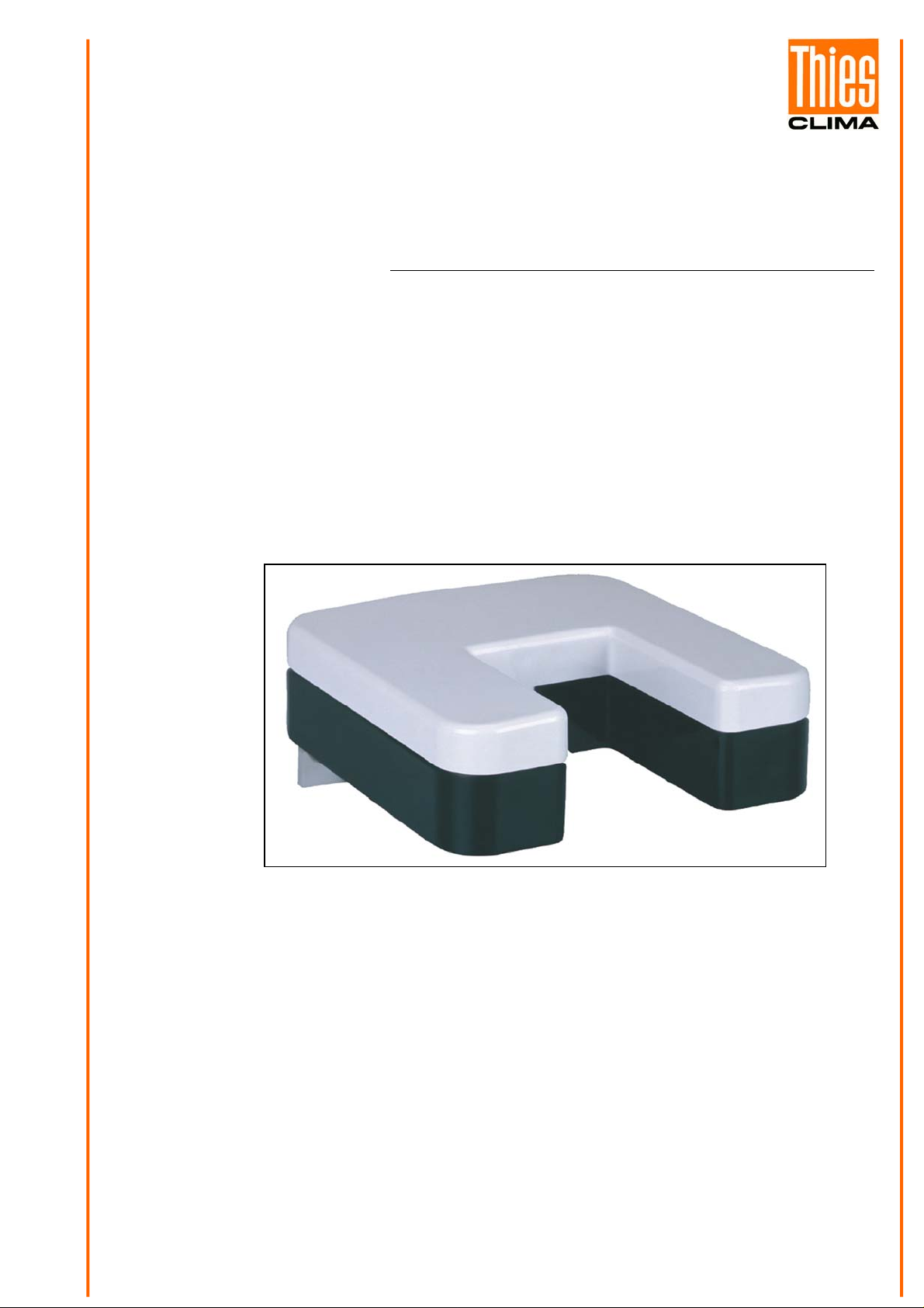
Precipitation Monito
5.4103.10.000, 5.4103.10.700
ADOLF THIES GmbH & Co. KG
Hauptstraße 76 37083 Göttingen Germany
Box 3536 + 3541 37025 Göttingen
Phone ++551 79001-0 Fax ++551 79001-65
THE WORLD OF WEATHER DATA - THE WORLD OF WEATHER DATA - THE WORLD OF WEATHER DATA
www.thiesclima.com info@thiesclima.com
Safety Instructions
• Before operating with or at the device/product, read through the operating instructions.
This manual contains instructions which should be followed on mounting, start-up, and operation.
A non-observance might cause:
- failure of important functions
- Endangering of persons by electrical or mechanic effect
- Damages at objects
• Mounting, electrical connection and wiring of the device/product must be carried out only by a qualified technician
who is familiar with and observes the engineering regulations, provisions and standards applicable in each case.
• Repairs and maintenance may only be carried out by trained staff or Adolf Thies GmbH & Co. KG. Only
components and spare parts supplied and/or recommended by Adolf Thies GmbH & Co. KG should be used for
repairs.
• Electrical devices/products must be mounted and wired only in voltage-free state.
• Adolf Thies GmbH & Co KG guarantees proper functioning of the device/products provided that no
modifications have been made to the mechanics, electronics or software, and that the following points are
observed:
• All information, warnings and instructions for use included in these operating instructions must be taken into
account and observed as this is essential to ensure trouble-free operation and a safe condition of the measuring
system / device / product.
• The device / product is designed for a specific application as described in these operating instructions.
• The device / product should be operated with the accessories and consumables supplied and/or recommended
by Adolf Thies GmbH & Co KG .
• Recommendation: As it is possible that each measuring system / device / product under certain conditions, and
in rare cases, may also output erroneous measuring values, it is recommended to use redundant systems with
plausibility checks with security-relevant applications.
Environment
• As a longstanding manufacturer of sensors Adolf Thies GmbH & Co KG is committed to the
objectives of environmental protection and is therefore willing to take back all supplied products
governed by the provisions of "ElektroG"
and to perform environmentally compatible disposal and recycling. We are prepared to take
back all Thies products concerned free of charge if returned to Thies by our customers
carriage-paid.
• Make sure you retain packaging for storage or transport of products. Should packaging
however no longer be required, arrange for recycling as the packaging materials are designed
to be recycled.
(German Electrical and Electronic Equipment Act)
Documentation
• © Copyright Adolf Thies GmbH & Co KG, Göttingen / Germany
• Although this operating instruction has been drawn up with due care, Adolf Thies GmbH & Co KG can accept
no liability whatsoever for any technical and typographical errors or omissions in this document that might
remain.
• We can accept no liability whatsoever for any losses arising from the information contained in this document.
• Subject to modification in terms of content.
• The device / product should not be passed on without the/these operating instructions.
2 - 12 021197/11/09

Contents
1 Model.........................................................................................................................................4
2 Application ................................................................................................................................. 4
3 Mode of Operation.....................................................................................................................4
4 Installation.................................................................................................................................. 4
4.1 Mechanical Mounting ..........................................................................................................5
4.2 Electrical Mounting for Precipitation with Cable Gland........................................................ 5
4.3 Electrical Mounting for Precipitation with Plug Connection................................................. 6
4.3.1 Plug Mounting...............................................................................................................6
5 Taking into Operation.................................................................................................................6
6 Maintenance .............................................................................................................................. 6
7 Setting of Incidences and Switch-off Delay................................................................................7
8 Connecting Diagram..................................................................................................................8
9 Technical Data........................................................................................................................... 9
10 Dimension diagram............................................................................................................... 10
11 Accessories.......................................................................................................................... 10
12 EC-Declaration of Conformity............................................................................................... 11
Tables
Table 1: DIP – switch adjustment.....................................................................................................7
3 - 12 021197/11/09
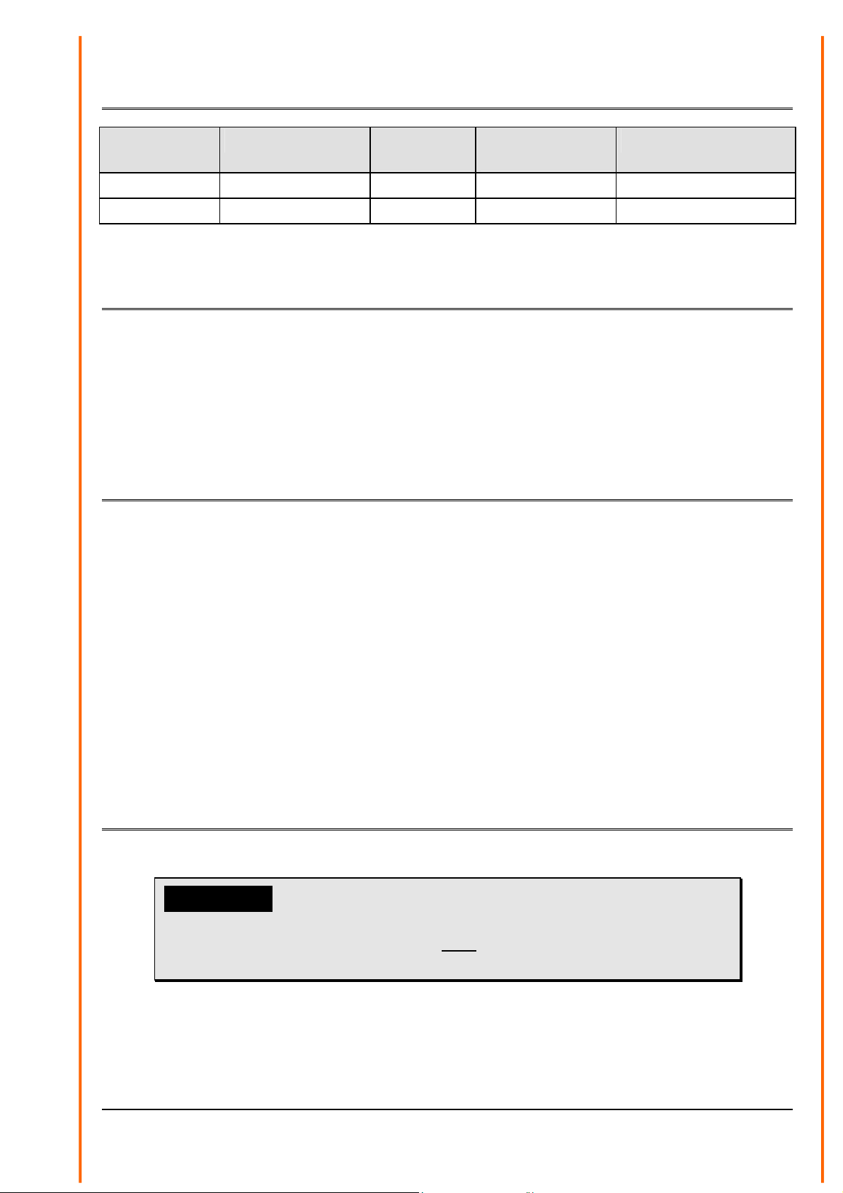
1 Model
Order - No. Measuring value Electrical
Output
5.4103.10.000 Precipitation status Relay 24 V AC/DC Cable gland
5.4103.10.700 Precipitation status Relay 24 V AC/DC 7- pole plug connection
Operating
Voltage
Connection
2 Application
The precipitation monitor transmits signals to determine the beginning and the end of precipitation
and the duration of the period of precipitation as required by meteorological services.
In addition, the precipitation monitor can be used to report status or to transmit control signals to
connected rain protection devices such as windows, air vents, awnings, or Venetian blinds.
3 Mode of Operation
Precipitation in the form of drizzle, rain, snow or hail is detected by means of a light barrier system
and triggers a signal. A built-in incidence-filter shall smooth the triggering of switching signals in
case of individual incidences, as for example leafs, bird droppings, insects etc. For this, a certain
number of at least n incidences should have occurred within a time-window of 50 sec. The number
of drop incidences (1…15) can be selected through the DIP-switch on the pc-board.
With the precipitation end the switching signal is reset after a selectable switch-off delay. Thanks to
the immediate evaluation of the incidences it is possible to determine precisely the beginning and
end of the precipitation period.
The instrument is equipped with a heating system for extreme weather condition. This avoids ice
and snow forming on the housing surface. In addition, the surface retains a temperature of >0° by
means of a regulated heating.
4 Installation
Please Note:
The electrical connection is to be carried out by experts only.
Please open the instrument only with dry ambient conditions.
Do not damage the exposed electronics!
4 - 12 021197/11/09

Remark:
In order to achieve an optimal electro-magnetic immunity (> 20 V/m) please use
shielded cable.
4.1 Mechanical Mounting
The mounting system of the instrument is designed for attachment to a mast. When mounting make
sure, that the precipitation can easily reach of the sensor field, and that the instrument, while
operating, is not exposed to strong vibrations or shocks.
Sensor field
4.2 Electrical Mounting for Precipitation with Cable Gland
To connect the instrument electrically, remove the cover with its 5 screws. The connecting
terminals and the DIP-switches for selecting the number of incidences and switch-off delays are
then accessible. The electrical connection is carried out according to the Circuit diagram. Insert the
cable from below through the screwed cable gland on the bottom of the case and connect it to the
connecting terminals and the shield connection. After the wiring – and mounting work is done, the
nuts of the screwed cable gland, and die screws of the cover are to be screwed evenly tight with
the case so that water cannot penetrate it. The fixing screws for the cover must be srewed down
with a torsional of 1 Nm to 2 Nm.
5 - 12 021197/11/09

4.3 Electrical Mounting for Precipitation with Plug Connection
The electrical connection is carried out by plug in accordance with the connecting diagram.
4.3.1 Plug Mounting
Applies only to instruments with connection „plug“.
Coupling socket, Typ:Binder, Serial 423, EMC with cable clamp
Cable connection: without cable shield
1. Stringing parts on cable acc. to plan given above.
2. Stripping cable sheath 20 mm
3. Cutting uncovered shield 20 mm
4. Stripping wire 5mm.
5. Soldering wire to the insert
6. Positioning shield in cable clamp.
7. Screwing-on cable clamp.
8. Assembling remaining parts acc. to upper plan.
9. Tightening pull-relief of cable by screw-wrench (SW16 und 17).
Cable- pull- relief
Wire
Cable clamp
Cable sheath
5 Taking into Operation
After the electrical connection has been established, and the case has been screwed, the operating
voltage can be switched on. The setting of the relay output is undefined after switching on the
operating voltage and shows „no precipitation“.
6 Maintenance
The device is maintenance free.
Cleaning:
The pollution and the pollution level is dependent on the location. Therefore, we recommend the
unit be checked at appropriate intervals and cleaned if necessary.
For the cleaning should use a damp cloth without chemical cleaning agents are used.
6 - 12 021197/11/09

7 Setting of Incidences and Switch-off Delay
In the factory a setting is carried out for 12 drop incidences within 50 seconds with a switchoff delay of 25 seconds.
If this setting is to be changed, the switch-off delay, and the number of drop incidences are set
through the DIP-switches acc. to the table.
DIP2
DIP1
DIP1- switch-off delay
S 1 S 2
ON OFF OFF OFF 25 ON OFF OFF OFF 1
OFF ON OFF OFF 50 OFF ON OFF OFF 2
ON ON OFF OFF 75 ON ON OFF OFF 3
OFF OFF ON OFF 100 OFF OFF ON OFF 4
ON OFF ON OFF 125 ON OFF ON OFF 5
OFF ON ON OFF 150 OFF ON ON OFF 6
ON ON ON OFF 175 ON ON ON OFF 7
OFF OFF OFF ON 200 OFF OFF OFF ON 8
ON OFF OFF ON 225 ON OFF OFF ON 9
OFF ON OFF ON 250 OFF ON OFF ON 10
ON ON OFF ON 275 ON ON OFF ON 11
OFF OFF ON ON 300 OFF OFF ON ON 12
ON OFF ON ON 325 ON OFF ON ON 13
OFF ON ON ON 350 OFF ON ON ON 14
ON ON ON ON 375 ON ON ON ON 15
S 3 S 4
DIP2- drop incidences-filter
Time(sec)
S 1 S 2 S 3 S 4
drops
Table 1: DIP – switch adjustment
• Grey marked squares = factory settings • DIP – switch adjustment „OFF, OFF, OFF, OFF“: not defined
7 - 12 021197/11/09

y
8 Connecting Diagram
Order-No.
5.4103.10.000
precipitation
yes
R
Pg
123 45
no
W
A
+-
Order-No.
5.4103.10.700
Plug connection
Precipitation
es
R
1 2 3 4 5
no
W A
7 pin Binder Plug
switch loading
max. 230V AC/DC
max . 4 A AC/DC
max. 1000VA (Ohm)
+ -
power supply
24V AC/DC
6 7
earth
View on the
soldering side of
the counter plug.
3
4
2
7
1
6
5
Switching load
max. 60 V AC / DC
max. 4A AC / DC
max. 1000VA (Ohm )
Power Supply
24V AC/DC
Earth
8 - 12 021197/11/09

9 Technical Data
Measuring value : Status of precipitation (rain, snow, hail, etc.)
Output : Precipitation = relay OFF ( also at U
= 0); no precipitation = relay ON
B
Sensor area : 25 cm2
Drop size
: ≥ 0,2 mm
Switch-on condition : 1... 15 incidences within 50 sec.
Switch-on delay : none
Switch-off delay : 25 ... 375 s ; see „Adjusting incidences and switch-off delay“
Contact loading (relay)
with model
5.4103.10.000
with model
5.4103.10.700
Operating voltage
Operation current
maximal
: max. 230 V AC; 4 A
: max. 60 V AC; 4 A
: 24 V AC/DC ± 15 %
: approx. 300 mA @20°C ambient temperature
: approx. 1 A
Ambient temperature : -30 ... +60°C
Protection : IP 65 acc. to DIN 40050
EMV : EN 61000-6-2 ; EN 61000-6-3
Weight : 0,4 kg
Connection See model
9 - 12 021197/11/09

10 Dimension diagram
11 Accessories
Power Supply Unit 9.3388.00.002 The power supply unit serves for the current
supply of the precipitation monitor, order-no.
5.4103.10.000. It supplies the necessary
operation voltage for the electronics and the
heating.
Primary : 230 V / 50 Hz
Secondary : 24 V AC / 20 VA
Housing : synthetic
Protection : IP 65 acc. with DIN 40050
Dimensions : 107 x 125 x 100 mm
Weight : 1,2 kg
10 - 12 021197/11/09

12 EC-Declaration of Conformity
Document-No.: 000902 Month: 06 Year: 08
Manufacturer: A D O L F T H I E S G m b H & C o. K G
Hauptstr. 76
D-37083 Göttingen
Tel.: (0551) 79001-0
Fax: (0551) 79001-65
Description of Product: Precipitation Transmitter
Article No.
specified technical data in the document:
The indicated products correspond to the essential requirement of the following European Directives and Regulations:
2004/108/EC DIRECTIVE 2004/108/EC OF THE EUROPEAN PARLIAMENT AND OF THE COUNCIL
2006/95/EC DIRECTIVE 2006/95/EC OF THE EUROPEAN PARLIAMENT AND OF THE COUNCIL
552/2004/EC Regulation (EC) No 552/2004 of the European Parliament and the Council of 10 March 2004
The indicated products comply with the regulations of the directives. This is proved by the compliance with the following
standards:
Reference number Specification
IEC 61000-6-2: 2005 Electromagnetic compatibility
IEC 61000-6-3: 2006 Electromagnetic compatibility
IEC 61010-1: 2001 Safety requirements for electrical equipment for measurement, control and
Place: Göttingen Date: 27.06.2008
email: Info@ThiesClima.com
5.4103.10.000 5.4103.10.012 5.4103.10.700 5.4103.20.041
5.4103.20.741 5.4103.30.000 5.4103.30.700
021324/10/04; 021196/12/04; 021334/04/05; 021469/08/05
of 15 December 2004 on the approximation of the laws of the Member States relating to
electromagnetic compatibility and repealing Directive 89/336/EEC
of 12 December 2006 on the harmonisation of the laws of Member States relating to electrical
equipment designed for use within certain voltage limits
on the interoperability of the European Air Traffic Management network
(the interoperability Regulation)
Immunity for industrial environment
Emission standard for residential, commercial and light industrial environments
laboratory use. Part 1: General requirements
This declaration certificates the compliance with the mentioned directives, howe er does not include any warranty of characteristics. v
Please pay attention to the security advises of the provided instructions for use.
11 - 12 021197/11/09

ADOLF THIES GmbH & Co. KG
Hauptstraße 76 37083 Göttingen Germany
P.O. Box 3536 + 3541 37025 Göttingen
12 - 12 021197/11/09
Phone ++551 79001-0 Fax ++551 79001-65
www.thiesclima.com info@thiesclima.com
- Alterations reserved-
 Loading...