

Thies CLIMA 4.3519.00.140, 4.3519.00.167, 4.3519.00.161, 4.3519.00.141, 4.3519.00.173 Instructions For Use Manual
...
Instruction for Use
021075/08/11
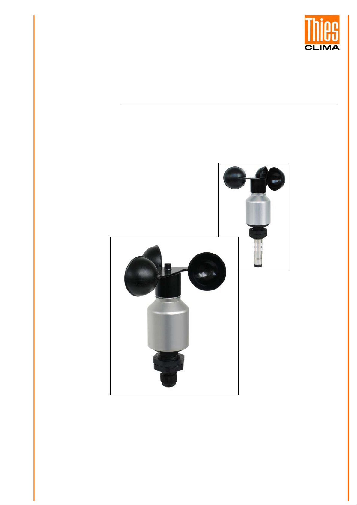
Wind Transmitter compact
4.3519.xx.140 ... 961
ADOLF THIES GmbH & Co. KG
Hauptstraße 76 37083 Göttingen Germany
Box 3536 + 3541 37025 Göttingen
Phone ++551 79001-0 Fax ++551 79001-65
www.thiesclima.com info@thiesclima.com
THE WORLD OF WEATHER DATA - THE WORLD OF WEATHER DATA - THE WORLD OF WEATHER DATA
Safety Instructions
• Before operating with or at the device/product, read through the operating instructions.
- failure of important functions
- Endangering of persons by electrical or mechanic effect
- Damages at objects
This manual contains instructions which should be followed on mounting, start-up, and operation.
A non-observance might cause:
• Mounting, electrical connection and wiring of the device/product must be carried out only by a qualified technician
who is familiar with and observes the engineering regulations, provisions and standards applicable in each case.
• Repairs and maintenance may only be carried out by trained staff or Adolf Thies GmbH & Co. KG. Only
components and spare parts supplied and/or recommended by Adolf Thies GmbH & Co. KG should be used for
repairs.
• Electrical devices/products must be mounted and wired only in voltage-free state.
• Adolf Thies GmbH & Co KG guarantees proper functioning of the device/products provided that no
modifications have been made to the mechanics, electronics or software, and that the following points are
observed:
• All information, warnings and instructions for use included in these operating instructions must be taken into
account and observed as this is essential to ensure trouble-free operation and a safe condition of the measuring
system / device / product.
• The device / product is designed for a specific application as described in these operating instructions.
• The device / product should be operated with the accessories and consumables supplied and/or recommended
by Adolf Thies GmbH & Co KG .
• Recommendation: As it is possible that each measuring system / device / product under certain conditions, and
in rare cases, may also output erroneous measuring values, it is recommended to use redundant systems with
plausibility checks with security-relevant applications.
Environment
• As a longstanding manufacturer of sensors Adolf Thies GmbH & Co KG is committed to the
objectives of environmental protection and is therefore willing to take back all supplied products
governed by the provisions of "ElektroG"
and to perform environmentally compatible disposal and recycling. We are prepared to take
back all Thies products concerned free of charge if returned to Thies by our customers
carriage-paid.
• Make sure you retain packaging for storage or transport of products. Should packaging
however no longer be required, arrange for recycling as the packaging materials are designed
to be recycled.
(German Electrical and Electronic Equipment Act)
Documentation
• © Copyright Adolf Thies GmbH & Co KG, Göttingen / Germany
• Although this operating instruction has been drawn up with due care, Adolf Thies GmbH & Co KG can accept
no liability whatsoever for any technical and typographical errors or omissions in this document that might
remain.
• We can accept no liability whatsoever for any losses arising from the information contained in this document.
• Subject to modification in terms of content.
• The device / product should not be passed on without the/these operating instructions.
2 - 14 021075/08/11

Contents
1 Models .......................................................................................................................................4
2 Application .................................................................................................................................5
3 Mode of Operation.....................................................................................................................5
4 Recommendation Site Selection / Standard Installation............................................................5
5 Installation.................................................................................................................................. 5
5.1 Mechanical Mounting .......................................................................................................... 6
5.2 Electrical Mounting..............................................................................................................6
5.3 Plug mounting ..................................................................................................................... 6
6 Connecting Diagram.................................................................................................................. 7
7 Maintenance ..............................................................................................................................8
8 Technical Data...........................................................................................................................9
9 Dimension diagram..................................................................................................................10
10 Accessories.......................................................................................................................... 11
11 EC-Declaration of Conformity...............................................................................................12
Figure
Figure 1: plug mounting.................................................................................................................... 6
Figure 2: Connecting Diagram for Models with fixed Connecting Cable.......................................... 7
Figure 3: Connecting Diagram for Models with Connector............................................................... 8
Figure 4: Dimensional Drawing Model cable gland........................................................................ 10
Figure 5: Dimensional Drawing Model plug.................................................................................... 10
3 - 14 021075/08/11

1 Models
Order - No. Electrical
Output
4.3519.00.140 0...20 mA 0...50 m/s 20 W 12 m Cable LiYCY 6 x 0,25 mm²
4.3519.00.141 4...20 mA 0...50 m/s 20 W 12 m Cable LiYCY 6 x 0,25 mm²
4.3519.00.161 0...10 V 0…50 m/s 20 W 12 m Cable LiYCY 6 x 0,25 mm²
4.3519.00.167 0...2 V 0…50 m/s 20 W 12 m Cable LiYCY 6 x 0,25 mm²
4.3519.00.173 0...5 V 0…50 m/s 20 W 12 m Cable LiYCY 6 x 0,25 mm²
Measuring
range
Heating
power
Connection
4.3519.00.361 0...10 V 0…3 m/s
max. 13,8 V
@ >3m/s
4.3519.00.441 4...20 mA 0…40 m/s 20 W 3 m PUR -Cable 6 x 0,25 mm²
4.3519.00.641 4...20 mA 0…60 m/s 20 W 12 m Cable LiYCY 6 x 0,25 mm²
4.3519.00.740 0…20 mA 0…50 m/s 20 W 7 pol. Plug
4.3519.00.741 4...20 mA 0…50 m/s 20 W 7 pol. Plug
4.3519.00.761 0...10 V 0...50 m/s 20 W 7 pol. Plug
4.3519.00.773 0...5 V 0...50 m/s 20 W 7 pol. Plug
4.3519.00.961 0...10 V 0…15 m/s 20 W 12 m Cable LiYCY 6 x 0,25 mm²
4.3519.01.140 0...20 mA 0…50 m/s 20 W 1,5 -3 m Spiral Cable LiYY 6x0,14 mm²
4.3519.02.141 4...20 mA 0…50 m/s 10 W 2 m Cable 6 x 0,56 mm²
4.3519.04.441 4...20 mA 0…40 m/s 20 W 0,95 m PUR- Cable 6 x 0,25 mm²
4.3519.05.141 4...20 mA 0…50 m/s 20 W 15 m Cable LiYCY 6 x 0,25 mm²
4.3519.05.161 0…10 V 0…50 m/s 20 W 15 m Cable LiYCY 6 x 0,25 mm²
4.3519.05.641 4...20 mA 0…60 m/s 20 W 15 m Cable LiYCY 6 x 0,25 mm²
4.3519.10.441 4...20 mA 0…40 m/s
20 W 12 m Cable LiYCY 6 x 0,25 mm²
Without heating
12 m Cable LiYCY 6 x 0,25 mm²
4.3519.20.141 4...20 mA 0...50 m/s 10 W 12 m Cable LiYCY 6 x 0,25 mm²
4.3519.39.141 4...20 mA 0…50 m/s 20 W 12 m Cable LiYCY 6 x 0,25 mm²
with cable lug at the shield
4.3519.40.140 0...20 mA 0...50 m/s 60 W 12 m Cable LiYCY 6 x 0,5 mm²
4.3519.40.141 4...20 mA 0...50 m/s 60 W 12 m Cable LiYCY 6 x 0,5 mm²
4.3519.40.161 0...10 V 0…50 m/s 60 W 12 m Cable LiYCY 6 x 0,5 mm²
4.3519.40.167 0...2 V 0…50 m/s 60 W 12 m Cable LiYCY 6 x 0,5 mm²
4.3519.40.173 0...5 V 0…50 m/s 60 W 12 m Cable LiYCY 6 x 0,5 mm²
4.3519.40.740 0…20 mA 0…50 m/s 60 W 7 pol. Plug
4.3519.40.741 4...20 mA 0…50 m/s 60 W 7 pol. Plug
4.3519.40.761 0...10 V 0...50 m/s 60 W 7 pol. Plug
4 - 14 021075/08/11

2 Application
The wind transmitter detects the horizontal wind speed. The measured values are available at the
output as analogue voltage or current signal to control for instance wind power plant..
An electronically-regulated heating system has been installed in some models (see chapter 1) for
winter time use, in order to prevent the ball-bearing and the external rotation parts from freezing.
Thanks to the 60-Watt-heating as well as to the optimized regulating characteristic, model no.
4.3519.40.xxx is especially suited for the extremely difficult application in high mountains or at other
critical sites, where icing is to be expected.
3 Mode of Operation
The cup star (in ball bearing) is set into rotation by the wind. An opto-electronic speed scanning
produces a frequency which is transformed into an analogue signal by an integrated measuring
transformer.
The outer parts of the instrument are made of corrosion-resistant materials. Labyrinth gaskets
protect the parts inside the instrument against precipitations.
4 Recommendation Site Selection / Standard Installation
In general wind measurement instruments should be able to detect the wind conditions of a large
area. In order to obtain comparable values when determining the surface wind, measurements
should be taken at a height of 10 meters over an even area with no obstacles. An area with no
obstacles means that the distance between the wind direction transmitter and an obstacle should
be at least 10 times the height of the obstacle (s. VDI 3786 ). If it is not possible to fulfil this
condition then the wind direction transmitter should be set up a height where local obstacles do not
influence the measured values to any significant extent (approx. 6-10 m above the obstacle). The
wind direction transmitter should be set up in the centre of flat roofs and not on the edge in order to
avoid any preferential directions.
5 Installation
Attention:
Storing, mounting and operation under weather conditions is
permissible only in vertical position, as otherwise water can get into
the instrument.
5 - 14 021075/08/11

Remark:
When using fastening adapters (angle, traverses, etc.) please take a possible
effect by turbulences into consideration.
Caution:
The device may only be supplied with a power supply of the
"Class , 2, limited power”.
5.1 Mechanical Mounting
The mounting of the wind transmitter could be done for example on a central mast tube with a Pg
21-boring thread, or on hangers or the like with a boring of ∅ 29 mm. In doing so please pay
attention to possible obstacles which might effect the air flow and the measuring value.
The connecting cable or the connector is guided through the boring, and the wind transmitter is
fixed with a hexagon nut (WO 36).
5.2 Electrical Mounting
For electrical connection please refer to the connecting diagram.
5.3 Plug mounting
Applies only to instruments with connection „plug“.
Coupling socket, Typ:Binder, Serial 423, EMC with cable clamp
Cable connection: without cable shield
1. Stringing parts on cable acc. to plan given above.
2. Stripping cable sheath 20 mm
3. Cutting uncovered shield 20 mm
4. Stripping wire 5mm.
5. Soldering wire to the insert
6. Positioning shield in cable clamp.
7. Screwing-on cable clamp.
8. Assembling remaining parts acc. to upper plan.
9. Tightening pull-relief of cable by screw-wrench (SW16 und 17).
Cable- pull- relief
Wire
Cable clamp
Cable sheath
Figure 1: plug mounting
6 - 14 021075/08/11

6 Connecting Diagram
Order – No.
4.3519.00.140
4.3519.00.141
4.3519.00.161*
4.3519.00.167
4.3519.00.173
4.3519.00.361*
4.3519.00.441
4.3519.00.641
4.3519.00.961*
4.3519.01.140
4.3519.02.141
4.3519.04.441
4.3519.05.141
4.3519.05.161
4.3519.05.641
4.3519.10.441
4.3519.20.141
4.3519.39.141
4.3519.40.140
4.3519.40.141
4.3519.40.161*
4.3519.40.167
4.3519.40.173
Separate Voltage Supply Shared Voltage Supply
Pg 9 Cable gland / Cable
yellow
6
grey
pink
~~
+
12345
brown
green
white
~~
+
+
Power
9 (13)...30 V D C
or 24 V AC
Heating
Analo g Output
Shield
Ground
Pg 9 Cable gland / Cable
1234
brown
white
56
green
yellow
grey
pink
~~
+
+
Power
24 V AC / DC
Shield
Ground
Order-No 4.3519.10.441 (Instrument without heating) Pin 5 and 6 not connected
Figure 2: Connecting Diagram for Models with fixed Connecting Cable
7 - 14 021075/08/11

Order – No.
4.3519.00.740
4.3519.00.741
4.3519.00.761*
4.3519.00.773
4.3519.40.740
4.3519.40.741
4.3519.40.761*
Separate Voltage Supply Shared Voltage Supply
~ ~
+
Power 9 (13).. 30 V DC
7 pol. Plug
+
or 24 V AC Analog Output
4 5
Heating
6
~ ~
+
Heating 24 V AC / DC
7 pol. Plug
7 1 2 3
1 2 3
~ ~
+
Power
24 V AC / DC
+
4 5
Analog Output
Heating
6
7
View on the
soldered joint
of the counter
plug
3
4
2
5
7
1
6
Figure 3: Connecting Diagram for Models with Connector
7 Maintenance
After proper mounting the instrument works maintenance free.
Heavy pollution can clog up the slit between the rotating and the stationary parts of the wind
transmitter. This slit must be kept clean.
Cleaning
For the cleaning of the device should use a damp cloth without chemical cleaning agents are used
8 - 14 021075/08/11

8 Technical Data
Measuring range See model
Resolution 0,1 m/s
Starting velocity
Accuracy
Measuring principle Opto-electronic (slotted disc)
Electrical output See model
Load
for current output (mA)
for current output (V)
Electrical supply for electronics
U: 9…30 V DC oder 24 V AC/DC I: 0,05A P: 1,5 W
*für 0 -10 V output U: 13…30 V DC oder 24 V AC/DC I: 0,05A P: 1,5 W
Electrical supply for heating
4.3519.00/01/02/04/05/20/39.xxx U: 24V AC/DC, 45…65Hz I: 0,83A P: 20 W
4.3519.20.xxx U: 24V AC/DC, 45…65Hz I: 0,42A P: 10 W
4.3519.40.xx U: 24V AC/DC, 45…65Hz I: 2,5A P: 60 W
Operating voltage heating
Survival speed maximally 80 m /s, 30 minutes
Connection See model
0,5 m/s
± 0,5 m/s or ± 3% of measuring value
max. 500 Ohm (for operating voltage > 15 V DC)
min. 1 KΩ
-40°C...70°C
Dimensions See dimensional drawing
Montage For ex. onto mast tube with receptacle thread Pg 21 or boring Ø 29 mm
Protection IP 55
Weight 0,40 – 0,75 kg depending on model
Material
Housing
Cup star
Bottom
Aluminium (AlMgSi1)
Synthetic, with fibre glass (PC-GF10)
Synthetic (POM H2320)
9 - 14 021075/08/11

9 Dimension diagram
Figure 4: Dimensional Drawing Model cable gland
Figure 5: Dimensional Drawing Model plug
10 - 14 021075/08/11

10 Accessories
For the wind transmitter the following accessories are available:
Traverse
For mounting the wind
transmitter and wind
direction transmitter
compact jointly onto a mast.
Traverse, short
For mounting the wind
transmitter compact onto a
mast.
Lightning Rod
For mounting onto the a/m
traverse
Other accessories such as cables, power supply units, masts as well as additional mast- or systemconstructions on request.
4.3171.30.000
4.3171.31.000
4.3171.40.000
4.3171.41.000
506351
Clamping range: Ø 48 ... 102 mm
Clamping range: Ø 116 ... 200 mm
Sensor distance: 0,8 m
Material: Aluminium
Clamping range: Ø 48 ... 102 mm
Clamping range: Ø 116 ... 200 mm
Length: 0,4 m
Material: Aluminium
Length: 0,56 m
Material: stainless steel
11 - 14 021075/08/11

11 EC-Declaration of Conformity
Document-No.: 001221 Month: 10 Year: 10
Manufacturer: A D O L F T H I E S G m b H & C o. K G
Hauptstr. 76
D-37083 Göttingen
Tel.: (0551) 79001-0
Fax: (0551) 79001-65
email: Info@ThiesClima.com
Description of Product: Wind Transmitter – compact analog
Article No.
4.3519.00.173 4.3519.00.361 4.3519.00.441 4.3519.00.641 4.3519.00.740
4.3519.00.741 4.3519.00.761 4.3519.00.773 4.3519.00.961 4.3519.01.140
4.3519.02.141 4.3519.02.441 4.3519.03.141 4.3519.04.441 4.3519.05.141
4.3519.05.161 4.3519.05.641 4.3519.06.441 4.3519.09.141 4.3519.10.441
4.3519.20.141 4.3519.39.141 4.3519.40.140 4.3519.40.141 4.3519.40.161
4.3519.40.167 4.3519.40.173 4.3519.40.740 4.3519.40.741 4.3519.40.761
4.3519.53.141 4.3519.83.141
4.3519.00.140 4.3519.00.141 4.3519.00.161 4.3519.00.167
specified technical data in the document:
021072/10/10; 021190/06/07; 021455/06/07; 021533/02/08
The indicated products correspond to the essential requirement of the following European Directives and Regulations:
2004/108/EC DIRECTIVE 2004/108/EC OF THE EUROPEAN PARLIAMENT AND OF THE COUNCIL
of 15 December 2004 on the approximation of the laws of the Member States relating to
electromagnetic compatibility and repealing Directive 89/336/EEC
2006/95/EC DIRECTIVE 2006/95/EC OF THE EUROPEAN PARLIAMENT AND OF THE COUNCIL
of 12 December 2006 on the harmonisation of the laws of Member States relating to electrical
equipment designed for use within certain voltage limits
552/2004/EC Regulation (EC) No 552/2004 of the European Parliament and the Council of 10 March 2004
on the interoperability of the European Air Traffic Management network
(the interoperability Regulation)
The indicated products comply with the regulations of the directives. This is proved by the compliance with the following
standards:
Reference number Specification
IEC 61000-6-2: 2005 Electromagnetic compatibility
Immunity for industrial environment
IEC 61000-6-3: 2006 Electromagnetic compatibility
Emission standard for residential, commercial and light industrial environments
IEC 61010-1: 2001 Safety requirements for electrical equipment for measurement, control and
laboratory use. Part 1: General requirements
Place: Göttingen Date: 04.10.2010
This declaration certificates the compliance with the mentioned directives, howe er does not include any warranty of characteristics. v
Please pay attention to the security advises of the provided instructions for use.
12 - 14 021075/08/11

13 - 14 021075/08/11

ADOLF THIES GmbH & Co. KG
Hauptstraße 76 37083 Göttingen Germany
P.O. Box 3536 + 3541 37025 Göttingen
14 - 14 021075/08/11
Phone ++551 79001-0 Fax ++551 79001-65
www.thiesclima.com info@thiesclima.com
- Alterations reserved-
 Loading...