

Thies CLIMA 4.3351.00.000, 4.3351.10.000 Instructions For Use Manual
Instruction for Use
021519/01/09
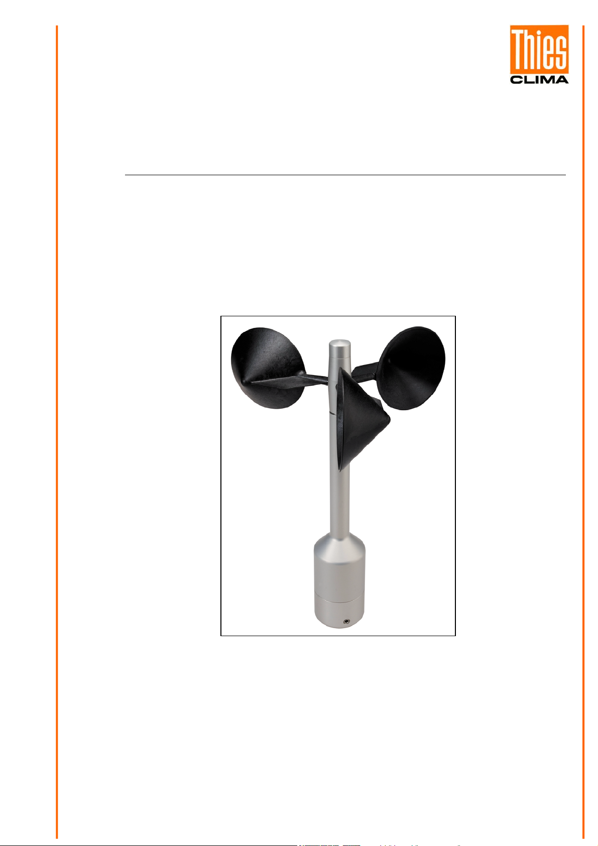
Wind Transmitter „First Class“ Advanced
Classified according to IEC 61400-12-1 (2005-12)
4.3351.00.000
4.3351.10.000
ADOLF THIES GmbH & Co. KG
Hauptstraße 76 37083 Göttingen Germany
Box 3536 + 3541 37025 Göttingen
Phone +49 551 79001-0 Fax +49 551 79001-65
THE WORLD OF WEATHER DATA - THE WORLD OF WEATHER DATA - THE WORLD OF WEATHER DATA
www.thiesclima.com info@thiesclima.com
Safety Instructions
• Before operating with or at the device/product, read through the operating instructions.
- failure of important functions
- Endangering of persons by electrical or mechanic effect
- Damages at objects
This manual contains instructions which should be followed on mounting, start-up, and operation.
A non-observance might cause:
• Mounting, electrical connection and wiring of the device/product must be carried out only by a qualified technician
who is familiar with and observes the engineering regulations, provisions and standards applicable in each case.
• Repairs and maintenance may only be carried out by trained staff or Adolf Thies GmbH & Co. KG. Only com-
ponents and spare parts supplied and/or recommended by Adolf Thies GmbH & Co. KG should be used for repairs.
• Electrical devices/products must be mounted and wired only in voltage-free state.
• Adolf Thies GmbH & Co KG guarantees proper functioning of the device/products provided that no modifica-
tions have been made to the mechanics, electronics or software, and that the following points are observed:
• All information, warnings and instructions for use included in these operating instructions must be taken into account and observed as this is essential to ensure trouble-free operation and a safe condition of the measuring
system / device / product.
• The device / product is designed for a specific application as described in these operating instructions.
• The device / product should be operated with the accessories and consumables supplied and/or recommended
by Adolf Thies GmbH & Co KG .
• Recommendation: As it is possible that each measuring system / device / product under certain conditions, and
in rare cases, may also output erroneous measuring values, it is recommended to use redundant systems with
plausibility checks with security-relevant applications.
Environment
• As a longstanding manufacturer of sensors Adolf Thies GmbH & Co KG is committed to the objectives of environmental protection and is therefore willing to take back all supplied products
governed by the provisions of "ElektroG"
and to perform environmentally compatible disposal and recycling. We are prepared to take
back all Thies products concerned free of charge if returned to Thies by our customers carriage-paid.
• Make sure you retain packaging for storage or transport of products. Should packaging however no longer be required, arrange for recycling as the packaging materials are designed to be
recycled.
(German Electrical and Electronic Equipment Act)
Documentation
• © Copyright Adolf Thies GmbH & Co KG, Göttingen / Germany
• Although this operating instruction has been drawn up with due care, Adolf Thies GmbH & Co KG can accept
no liability whatsoever for any technical and typographical errors or omissions in this document that might remain.
• We can accept no liability whatsoever for any losses arising from the information contained in this document.
• Subject to modification in terms of content.
• The device / product should not be passed on without the/these operating instructions.
2 - 16 021519/01/09

Contents
1 Models available ........................................................................................................................ 4
2 Application ................................................................................................................................. 4
3 Construction and Mode of Operation ......................................................................................... 4
4 Recommendation Side Selection / Standard Installation ........................................................... 5
5 Installation.................................................................................................................................. 5
5.1 Mechanical Mounting .......................................................................................................... 6
5.2 Electrical Mounting .............................................................................................................. 6
5.2.1 Cable ............................................................................................................................ 6
5.2.1.1 Cable Recommendation......................................................................................... 6
5.2.2 Cable Shield ................................................................................................................. 6
5.2.2.1 Connecting Recommendation for the Cable Shield ............................................... 7
5.2.3 Plug and Cable Mounting ............................................................................................. 8
5.3 Connecting Diagram............................................................................................................ 9
6 Maintenance ............................................................................................................................ 10
7 Technical Data......................................................................................................................... 11
8 Dimensional Drawing ............................................................................................................... 12
9 Accessories (optional) ............................................................................................................. 13
10 EC-Declaration of Conformity............................................................................................... 14
Patent
Patent Nr.: EP 1 398 637
Patent Nr.: DE 103 27 632
Patent Nr.: EP 1 489 427
3 - 16 021519/01/09

1 Models available
Order - No. Meas. range
4.3351.00.000 0.3...75 m/s 1082 Hz @ 50 m/s 3.3…48 V DC 24V AC/DC, 25 W
4.3351.10.000 0.3...75 m/s 1082 Hz @ 50 m/s 3.3…48 V DC w/o heating
The following parts are included in delivery:
1 Instrument
1 Terminal plug
1 Instruction for Use
Output
Frequency
Supply Heating
2 Application
The wind transmitter is designed for the acquisition of the horizontal component of the wind speed
in the field of meteorology and environmental measuring technology, evaluation of location, and
measurement of capacity characteristics of wind power systems.
Special characters are defined and optimised, dynamic behaviour also at high turbulence intensity,
minimal over-speeding, and a low starting values.
The measuring value is available as digital signal at the output. It can be transmitted to display instruments, recording instruments, data loggers as well as to process control systems. For winter
operation the instrument is optional equipped with an electronically regulated heating, which guarantees a smooth running of the ball bearings, and prevents the shaft and slot from icing-up.
3 Construction and Mode of Operation
A low-inertia cup star with 3 cups, made of carbon-fibre-reinforced plastic, is set into rotation by the
wind. The rotation is scanned opto-electronically, and is converted into a square wave signal. The
frequency of this signal is proportional to the number or rotations. Depending on the supply voltage,
the output signal ranges between maximal output voltage and ground or a potential (life-zero
lifted by approx. 1.2 V. The supply of the electronics can be done by DC-voltage of 3.3 V up to 48 V
at a very low current consumption. An AC- or DC-voltage of 24 V is intended for the separate supply of the optional heating. In all probability, the heating guarantees a trouble-free function of the
Wind Transmitter First Class even under extreme meteorological icing-conditions.
The outer parts of the instrument are made of corrosion-resistant anodised aluminium. Highly effective labyrinth gaskets and O-rings protect the sensitive parts inside the instrument against humidity
and dust. The instrument is mounted onto a mast tube; the electrical plug-connection is located in
the transmitter shaft.
*
),
*
Useable at a supply voltage > 5 V DC
4 - 16 021519/01/09
4 Recommendation Side Selection / Standard Installation
In general, wind measuring instruments are supposed to record wind conditions over a large area.
According to international regulations, the surface wind should be measured at a height of 10 m
above even open terrain, in order to achieve comparable values. An open terrain is defined as terrain where the distance between the wind-measuring instrument and the next obstacle is at least
ten times the height of this obstacle (acc. to VDI 3786 sheet 2 as well as Guide to Meteorological
Instruments and Methods of Observation, Sixth Edition, WMO-No. 8). If this regulation cannot be
fulfilled, the measuring instrument should be installed at a height at where the measurement values
are not influenced by any local obstacles. In any case, the measuring instruments should be installed at a height of 6 to 10 m above the mean height of the buildings or trees in the vicinity. If it is
necessary to install the instrument on a roof, it should be installed in the centre of the roof in order
to avoid any preferential directions.
5 Installation
Attention:
Storing, mounting, and operation under weather conditions is permissible only in vertical position, as otherwise water can get into the
instrument.
Remark:
When using fastening adapters (angle, traverses, etc) please take a possible effect to the measuring values by shading into consideration.
Caution:
The device may only be supplied with a power supply of the
"Class 2, limited power”.
5 - 16 021519/01/09
 Loading...