

Thies CLIMA 4.3151.x0.400 Series, 4.3151.10.400, 4.3151.00.400, First Class Instructions For Use Manual
THE WORLD OF WEATHER DATA - THE WORLD OF WEATHER DATA - THE WORLD OF WEATHER DATA
Instruction for Use
ADOLF THIES GmbH & Co. KG
021754/05/14
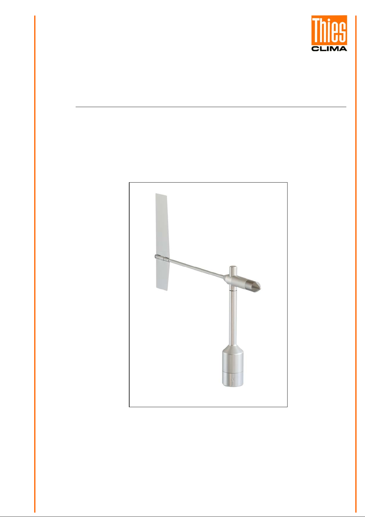
Wind Direction Transmitter „First Class“
- Device with digital output, RS 485
- Wind velocity signal acquisition
4.3151.x0.400
Hauptstraße 76 37083 Göttingen Germany
Box 3536 + 3541 37025 Göttingen
Phone +49 551 79001-0 Fax +49 551 79001-65
www.thiesclima.com info@thiesclima.com

Contents
1 Models available ....................................................................................................................... 4
2 Application ................................................................................................................................ 4
3 Mode of Operation .................................................................................................................... 5
4 Recommendation Site Selection / Standard Installation ............................................................ 5
5 Installation ................................................................................................................................. 6
5.1 Wind Vane Mounting .......................................................................................................... 6
5.2 Mechanical Mounting .......................................................................................................... 7
5.2.1 North Alignment ........................................................................................................... 8
5.3 Electrical Mounting ............................................................................................................. 9
5.3.1 Cable ........................................................................................................................... 9
5.3.1.1 Cable Recommendation ........................................................................................ 9
5.3.2 Cable Shield ................................................................................................................. 9
5.3.2.1 Connecting Recommendation for the Cable Shield ................................................ 9
5.3.3 Plug and Cable Mounting ........................................................................................... 10
6 Connecting Diagram ............................................................................................................... 11
6.1 Example Connection Diagram .......................................................................................... 12
7 Serial Interface (RS485) ......................................................................................................... 12
8 Placing into operation ............................................................................................................. 13
9 Serial Communication ............................................................................................................. 13
10 List of Commands ................................................................................................................ 14
11 Commands and Description ................................................................................................. 14
Command KY ......................................................................................................................... 14
Command TR ......................................................................................................................... 15
Command BR ......................................................................................................................... 15
Command TT .......................................................................................................................... 15
Command OR ......................................................................................................................... 16
Command ID ........................................................................................................................... 16
12 Data Telegram ..................................................................................................................... 17
13 Maintenance ........................................................................................................................ 17
14 Technical Data ..................................................................................................................... 18
15 Dimensional drawing ............................................................................................................ 19
16 Accessories ......................................................................................................................... 20
17 EC-Declaration of Conformity .............................................................................................. 21
2 - 22 021754/05/14
Safety Instructi o ns
• Before operating with or at the device / product, read through the operating instructions.
- failure of important functions
- Endangering of persons by electrical or mechanic effect
- Damages at objects
This manual contains instructions which should be followed on mounting, start-up, and operation.
A non-observance might cause:
• Mounting, electrical connection and wiring of the device / product must be carried out only by a qualified techni-
cian who is familiar with and observes the engineering regulations, provisions and standards applicable in each
case.
• Repairs and maintenance may only be carried out by trained staff or Adolf Thies GmbH & Co. KG. Only com-
ponents and spare parts supplied and / or recommended by Adolf Thies GmbH & Co. KG should be used for
repairs.
• Electrical devices / products must be mounted and wired only in voltage-free state.
• Adolf Thies GmbH & Co KG guarantees proper functioning of the device / products provided that no modifica-
tions have been made to the mechanics, electronics or software, and that the following points are observed:
• All information, warnings and instructions for use included in these operating instructions must be taken into ac-
count and observed as this is essential to ensure trouble-free operation and a safe condition of the measuring
system / device / product.
• The device / product is designed for a specific application as described in these operating instructions.
• The device / product should be operated with the accessories and consumables supplied and/or recommended
by Adolf Thies GmbH & Co KG.
• Recommendation: As it is possible that each measuring system / device / product under certain conditions, and
in rare cases, may also output erroneous measuring values, it is recommended to use redundant systems with
plausibility checks with security-relevant applications.
Environment
• As a longstanding manufacturer of sensors Adolf Thies GmbH & Co KG is committed to the
objectives of environmental protection and is therefore willing to take back all supplied prod-
ucts governed by the provisions of "ElektroG"
Act) and to perform environmentally compatible disposal and recycling. We are prepared to
take back all Thies products concerned free of charge if returned to Thies by our customers
carriage-paid.
• Make sure you retain packaging for storage or transport of products. Should packaging how-
ever no longer be required, arrange for recycling as the packaging materials are designed to
be recycled.
(German Electrical and Electronic Equipment
Documentation
• © Copyright Adolf Thies GmbH & Co KG, Göttingen / Germany
• Although this operating instruction has been drawn up with due care, Adolf Thies GmbH & Co KG can accept
no liability whatsoever for any technical and typographical errors or omissions in this document that might remain.
• We can accept no liability whatsoever for any losses arising from the information contained in this document.
• Subject to modification in terms of content.
• The device / product should not be passed on without the / these operating instructions.
3 - 22 021754/05/14

Meas. range
Input [Hz]
Output
1 Models available
Order - No. Wind direction
4.3151.00.400 0...360° 1082 Hz @ 50m/s RS 485 3,3V…42V DC with
4.3151.10.400 0...360° 1082 Hz @ 50m/s RS 485 3,3V…42V DC without
Wind velocity
Electrical
Supply Heating
(24 V AC / DC)
2 Application
The wind direction transmitter serves for the detection of the horizontal wind direction in the field
of meteorology and the technology of environmental protection.
The measuring value is available as serial data telegram via an RS485 interface. The data telegram is able to operate, f or ex., wind displays, weather displays, datalogg ers, process control systems or to communicate with PC and software “Meteo-Online”.
The wind direction transmitter can acquire wind velocity signals and can complete its s er ial data
telegram by the parameter wind velocity.
Special characteristics:
• High level of measuring accuracy and resolution
• High damping ratio at a small delay distance
• Low starting threshold
• Low current consumption (3,3V – 15V @6,0mA)
• Option for connecting an anemom eter „First Class 4.3351.x0.000“.
• Data telegram additionally with wind velocity
For wintertime use the wind direction transmitter (see chapter 1 models available) is optionally
equipped with an electronically regulated heating, which guarantees the smooth running of the ball
bearing, and prevents ice forming in the space between the external rotation parts.
4 - 22 021754/05/14

3 Mode of Operation
Wind direction
The dynamic characteristics of t he wind vane is achieved by the aluminum lightweight construction.
The co-action of wind vane and balance weight results in a high damping rat i o with s mall delay
distance as excellent characteristic of the com plet e vane.
The axis of the wind vane is running in ball bearings and carries a diametrically magnet ized magnet
at the inner end. The angle position of t he axis is scanned cont act-free by a magnetic angle sensor
(TMR-Sensor, Tunnel Magneto Resistance) through the position of the magnet field. As the sensor
is operated in magnetic saturation, effects by external magnetic fields can almost be eliminated.
The connected electronics calculates the angle position of the axis and provides the respective
serial output signal.
Acquisition of Wind Velocity
Additionally to the wind direction acquisition the wind direction transmitter offers the option of supplying the wind velocity signal from the Wind transmit t er Fir st Class 4.3351.x0.000. The wind velocity signal is acquired and analyzed and is available in the output telegram along with the acquired
wind direction.
General
An AC- or DC-voltage of 24 V is intended for the separate supply of the optional heating . I n all
probability, the heating guarantees a tr ouble-free function of t he Wind Direction Tr ansmitter First
Class even under extreme meteorological icing-conditions.
The outer parts of t he inst r um ent are made of corrosion-resistant anodized aluminum, and stainless steel. Highly effective labyrinth gask ets and O-rings protect the s ensit ive parts inside the instrument against humidity and dust.
4 Recommendation Site Selection / Standard Installation
In general wind measurement instruments should be able t o detect the wind conditions of a large
area. In order to obtain comparable values when determining the surface wind, measurements
should be taken at a height of 10 m eters over an even area with no obstacles. An area with no obstacles means that the distance bet ween the wind direction transmitter and an obstacle should be
at least 10 times the height of t he obstacle (s. VDI 3786 Part 2). If it is not possible to fulfill this
condition then the wind direction transmitter should be set up a height where local obstacles do not
influence the measured values to any significant extent (approx. 6 - 10 m above the obstacle). The
wind direction transmitter should be set up in the center of f lat roof s and not on the edge in order to
avoid any preferential directions.
5 - 22 021754/05/14
5 Installation
Attention:
Storing, mounting and operation under weather conditions is permissible only in vertical position, as otherwise water can get into the instrument.
Remark:
When using fastening adapters (angle, tr av er ses , et c.) please take a possible effect on the measurements by tur bulences into c onsideration.
Caution:
The device may only be supplied with a power supply of the
"Class 2, limited power”.
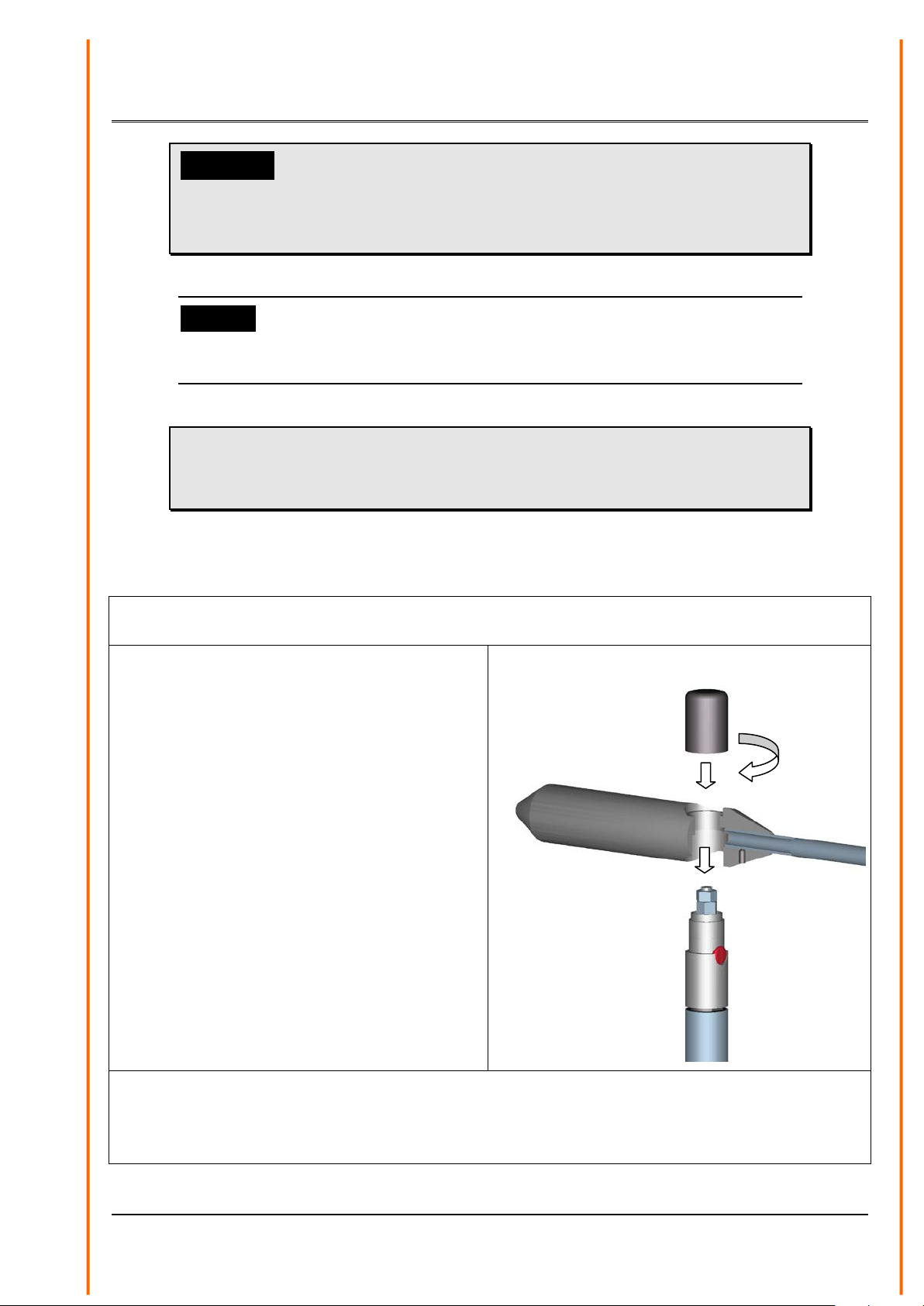
5.1 Wind Vane Mounti ng
Before the wind direction transmitter c an be inst alled at it s s elect ed sit e, the wind vane must be
mounted on the housing.
Tools:
Not required
Procedure
1. Remove wind transmitter housing from
the packing.
2. Remove cap by counter-clockwise rotation.
3. Remove wind vane from the packing
4. Mount the wind vane on the housing acc.
to figure.
5. Wind vane rotate until it falls into the
guide.
6. Put the cap on the thr ead, and tighten it
manually by strong clockwise rotation.
Please do not use tools.
Remark
The wiring must be prepared so far , t hat plug and cable have been pushed through instrument carrier, mast, traverse etc. , and c an be connec t ed t o the wind direction transmitter at the moment of
the ”Mechanical Mounting”, described in the following (please refer also t o chapt er 5.4).
6 - 22 021754/05/14
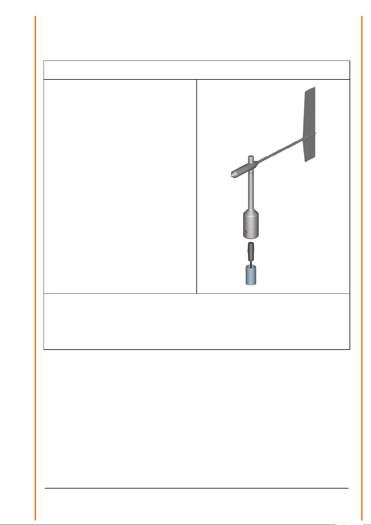
5.2 Mechanical Mounting
The wind direction transmitter must be m ounted on an instrument carrier, which is suited for t he
measurement. For dimensions of wind direction tr ansm it ter please refer to chapter 10.
Tools:
Hexagon socket wrench SW3
(Allen key)
Procedure:
1. Push cable/ plug connector of the wind
direction transmitter through the borehole
of the mast, tube, ar m etc.
2. Put wind direction transmitter on mast,
tube, arm etc.
3. Align the wind direction transmitter
“northwards” (procedure see chapter
5.2.1).
4. Safeguar d the wind direction transmitter
by two M6-Allen head screws
Remark:
Suitable instrument carriers are mast s , t ubes , t r averses , ar m s , adapt ers, adapters of POM for isolated mounting, which correspond to the mounting dimensions of the wind transmitter, and t o the
static requirements.
The inner diameter of the instrument carrier should be ≥ 20 mm based on plug- and cable feedthrough.
7 - 22 021754/05/14
 Loading...