

Page 1
THE WORLD OF WEATHER DATA - THE WORLD OF WEATHER DATA - THE WORLD OF WEATHER DATA
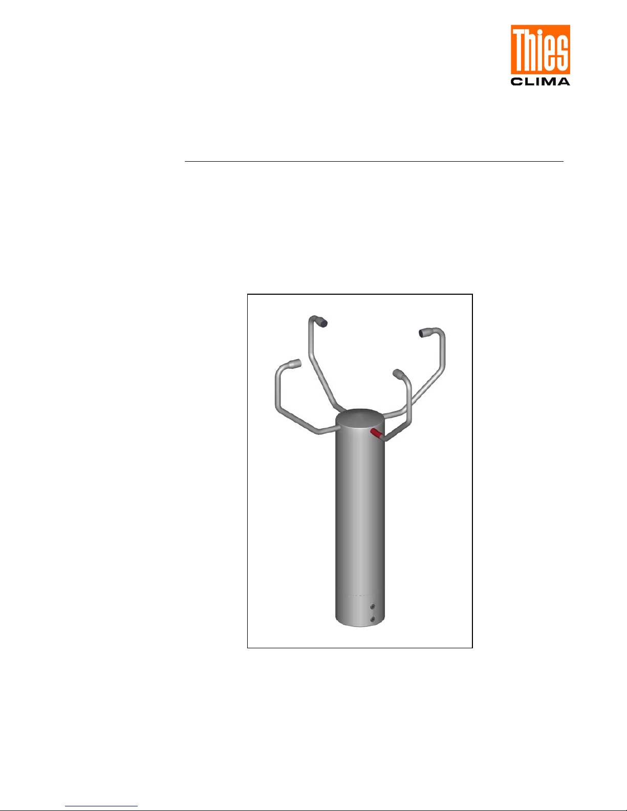
Ultrasonic Anemometer 2
D
4.3811.00.000
Software version V2.00 or higher Status: 10/2006
Operating Instructions
021511/10/06
ADOLF THIES GmbH & Co. KG
Hauptstraße 76 37083 Göttingen Germany
Box 3536 + 3541 37025 Göttingen
Phone ++551 79001-0 Fax ++551 79001-65
www.thiesclima.com info@thiesclima.com
Page 2

4.3811.00.000_US-Anemometer-DSP_eng.doc 2 - 26 021511/10/06
Contents
1 Application ................................................................................................................................. 4
2 Mode of Operation ..................................................................................................................... 4
2.1 Measuring principle: Wind velocity and direction ................................................................ 5
2.2 Measuring principle: Acoustic virtual temperature............................................................... 6
3 Preparation for Operation / Installation ...................................................................................... 6
3.1 Selection of installation site ................................................................................................. 7
3.2 Installation of anemometer .................................................................................................. 7
3.3 Alignment to north ............................................................................................................... 7
3.4 Cables, cable preparation, connector installation................................................................ 7
3.5 Connector pin assignment................................................................................................... 9
4 Maintenance .............................................................................................................................. 9
5 Calibration................................................................................................................................10
6 Warranty .................................................................................................................................. 10
7 Functional Description ............................................................................................................. 11
7.1 Serial communication ........................................................................................................ 11
7.1.1 General telegram structure ......................................................................................... 12
7.1.2 Return values of ULTRASONIC.................................................................................. 13
7.1.3 Access mode .............................................................................................................. 13
7.1.4 Device ID .................................................................................................................... 14
7.1.5 Bus mode.................................................................................................................... 14
7.2 Data acquisition................................................................................................................. 14
7.2.1 Averaging.................................................................................................................... 14
7.3 Serial data output .............................................................................................................. 15
7.3.1 Data enquiry ............................................................................................................... 15
7.3.2 Fixed telegram formats ............................................................................................... 15
00005 ............................................................................................................................................. 15
7.4 Generation of check sum .................................................................................................. 16
7.5 Status information ............................................................................................................. 16
7.5.1 Definition of status byte version 1............................................................................... 16
7.5.2 Structure of status byte version 1 ............................................................................... 16
7.5.3 Definition of temperature difference in status byte ..................................................... 17
7.5.4 Definition of averaging memory used ......................................................................... 17
7.6 Behaviour in fault conditions ............................................................................................. 17
7.7 Heating control .................................................................................................................. 17
7.8 Output of all system parameters ....................................................................................... 18
7.9 Enquiry about software version ......................................................................................... 18
7.10 Forcing a restart ................................................................................................................ 18
7.11 Bootloader ......................................................................................................................... 18
7.12 Online Help........................................................................................................................ 18
8 Configuration of Ultrasonic Anemometer by Customer............................................................ 19
9 Command List, Short ............................................................................................................... 20
10 Predefined Data Telegram.................................................................................................... 22
Page 3

4.3811.00.000_US-Anemometer-DSP_eng.doc 3 - 26 021511/10/06
11 Technical Data...................................................................................................................... 23
12 Dimension Drawing .............................................................................................................. 25
13 Accessories (available as optional features) ........................................................................ 25
Fig.
Fig. 1: Connector assembly.............................................................................................................. 8
Table
Table 1: Return values with incorrect interpretation of command .................................................. 13
Table 2: Access key for different command levels ......................................................................... 13
Table 3: List of predefined data telegrams ..................................................................................... 15
Page 4

4.3811.00.000_US-Anemometer-DSP_eng.doc 4 - 26 021511/10/06
1 Application
The Ultrasonic Anemometer 2D is used to detect the horizontal components of wind velocity and
wind direction as well as the virtual temperature in 2 dimensions.
Due to the measuring principle the instrument is ideal for inertia-free measurement of gusts and
peak values.
The level of accuracy achieved when measuring the air temperature (virtual temperature)
surpasses that of classical methods, in which the temperature sensors are used with weather and
radiation protection, following correction of the influence of damp occurring with certain weather
situations.
Output of the measured values is digital. An RS485 in half duplex mode is available for serial
communication.
Serial output of the data is as a sliding mean.
The sensor arms are automatically heated if necessary with critical ambient temperatures. This also
ensures functionality with snowfall and sleet and minimises the risk of malfunctions due to icing-up.
The model No. 4.3811.00.000 has additional protection from mechanical stresses such as ice
fracture and attack by birds by means of metal encapsulated ultrasonic transformers.
These Operating Instructions relate to the device version 4.3811.00.000. They describe possible
applications and settings.
The Ultrasonic Anemometer 2D is factory-set. Identification for the factory setting is via the order
No. and "Factory Setting".
Order number and setting
see supplementary sheet "Factory Setting"
In addition, the default settings for device version 4.3811.00.000 are marked in "grey" in these
Operating Instructions.
2 Mode of Operation
The Ultrasonic Anemometer 2D consists of 4 ultrasonic transformers, in pairs of two facing each
other at a distance of 200 mm. The two resulting measurement paths are vertical to each other.
The transformers function both as acoustic transmitters and receivers.
The electronic control system is used to select the respective measurement path and its measuring
direction. When a measurement starts, a sequence of 4 individual measurements is performed in
all 4 directions of the measurement paths at maximum speed.
The measuring directions (sound propagation directions) rotate clockwise, first from south to north,
then from west to east, from north to south and finally from east to west.
The mean values are worked out from the 4 individual measurements of the path directions and
used to make further calculations..
Page 5
The time required for a measuring sequence is approx. 2.5 msec at +20°C at the maximum
measuring speed.
2.1 Measuring principle: Wind velocity and direction
The speed of propagation of the sound in calm air is superposed by the velocity components of an
air flow in the direction of the wind.
A wind velocity component in the propagation direction of the sound supports the speed of
propagation; i.e. it increases it while a wind velocity component against the propagation direction
reduces the speed of propagation.
The propagation speed resulting from superposition leads to different propagation times of the
sound at different wind velocities and directions over a fixed measurement path.
As the speed of sound greatly depends on the temperature of the air, the propagation time of the
sound is measured on each of the two measurement paths in both directions. This rules out the
influence of temperature on the measurement result.
By combining the two measurement paths which are at right angles to each other, the
measurement results of the sum and the angle of the wind velocity vector are obtained in the form
of perpendicular components.
After the perpendicular velocity components have been measured, they are then converted to polar
coordinates by the µ processor of the anemometer and output as a sum and angle of wind velocity.
Wind from NNE
Y-component
X-component
E
N
W
S
4.3811.00.000_US-Anemometer-DSP_eng.doc 5 - 26 021511/10/06
Page 6

4.3811.00.000_US-Anemometer-DSP_eng.doc 6 - 26 021511/10/06
2.2 Measuring principle: Acoustic virtual temperature
The speed of propagation of the sound depends on the absolute temperature of the air via a root
function although it is more or less independent of the air pressure and only depends on the air
humidity to a minor extent. We can thus make use of these physical properties for temperature
measurement of air with a known and constant chemical composition.
Here we measure gas temperature without the indirect step of thermal coupling involving this gas to
a sensor.
The advantages of this measuring method are firstly an inertia-free reaction to the actual gas
temperature, and secondly, the avoidance of measuring errors such as those that occur for
example when a solid-state temperature sensor is heated by radiation.
Due to the low dependence of the speed of propagation of the sound on the air humidity level the
"acoustic virtual temperature" relates to dry air (0% humidity) under the same pressure conditions
as those actually measured.
The deviation of the measured "acoustic virtual temperature" from the real air temperature shows
linear dependence on the absolute humidity level of the air.
The amount of water vapour in the air proportionately increases the speed of the sound as H
2
O
molecules only have around half the mass of the other air molecules (O
2
and N2).
The increase in the speed of the sound results in an apparent (virtual) increase in the measured
temperature of humid air in comparison to dry air of the same temperature.
The deviation of the measured virtual temperature of humid air from the real air temperature can be
corrected for instance according to the following relationship if the absolute humidity is known:
T
r
= Tv – 0.135 K * m3 / g * a
where T
r
is the real air temperature, Tv the measured acoustic virtual temperature and a the
absolute humidity in grammes H
2
O per m3 air.
With an air temperature of 20°C the virtual temperature is around 2 K too high with 100% rel.
humidity.
3 Preparation for Operation / Installation
Attention:
The working position of the anemometer is vertical (sensor
arms "above", connector "below").
During installation, de-installation, transport or maintenance of
the anemometer it must be ensured that no water gets into the
shaft or connector of the anemometer.
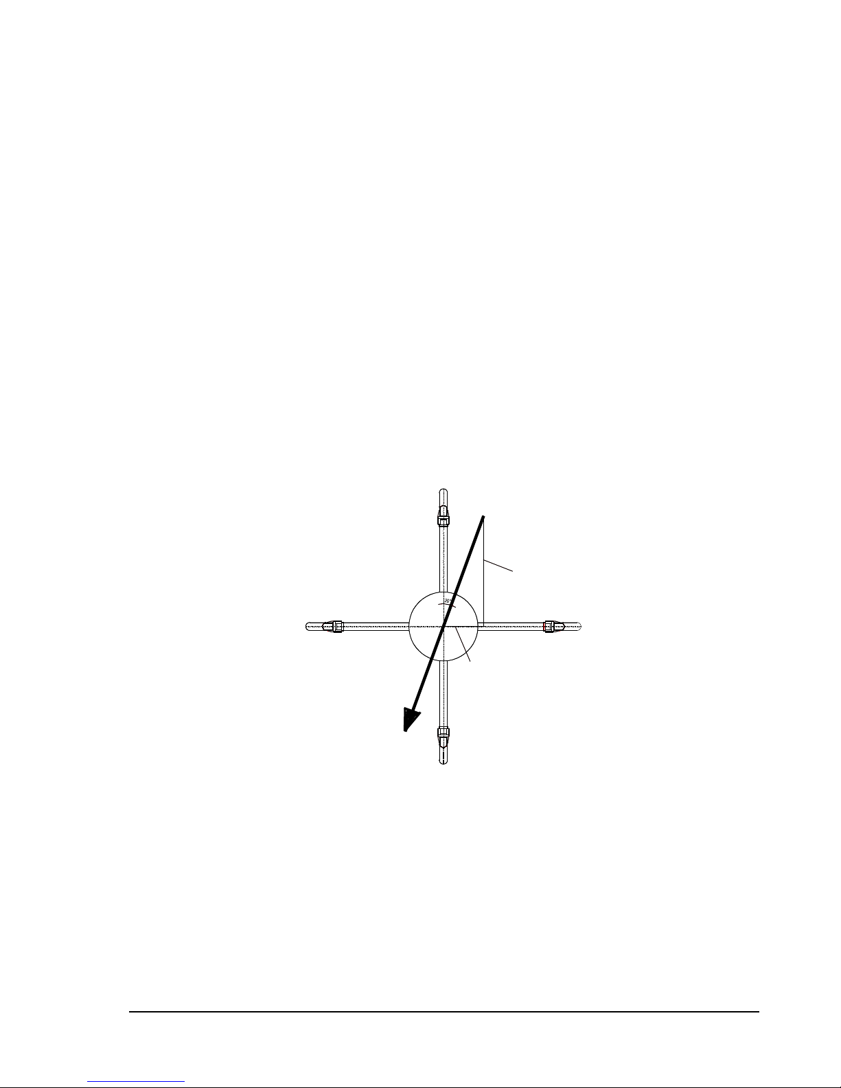
When using a lightning rod it must be borne in mind that it
should always be installed less than 45° to a measurement
path; otherwise there will be deviations in the measured values.
Page 7

4.3811.00.000_US-Anemometer-DSP_eng.doc 7 - 26 021511/10/06
3.1 Selection of installation site
As already described, the ultrasonic anemometer transmits sound packages required to measure
the propagation speed. If these sound packages meet surfaces that reflect sound, they are thrown
back as an echo and can may result in incorrect measurements under unfavourable conditions.
It is therefore advisable to install the ultrasonic anemometer at a minimum distance of 1 metre to
objects in the measuring level.
In general, wind meters should register wind conditions over a wide area. To obtain comparable
values when measuring the ground wind, measurement should be performed at a height of 10
metres above even and undisrupted terrain. Undisrupted terrain means that the distance between
the wind transmitter and the obstruction should be at least ten times the height of the obstruction (s.
VDI 3786). If it is not possible to comply with this provision, the wind meter should be installed at a
height at which measured values are influenced by obstructions located in the vicinity to the least
possible extent (approx. 6-10 m above the interference level). On flat roofs the anemometer should
be installed in the middle of the roof and not at the edge to thus avoid any preferential directions.
3.2 Installation of anemometer
Proper installation of the ultrasonic anemometer is carried out using a tube socket R1½" (Ø 48.3
mm) and 50 mm in length The inside diameter of the tube socket must be at least 40 mm as the
ultrasonic anemometer is electrically connected to the connector (s. Accessories: connecting cable,
compl.) from below. After connection the ultrasonic anemometer is fitted on the tube or mast
socket. The arm of the sonic transformer marked red must be aligned to north. This allows a
bearing to be taken from an object located to the north, e.g. a building or special geographical
feature, using the sonic transformers of the north / south measurement path.
The instrument is fixed to the shaft with the four Allen screws (AF 4 mm).
3.3 Alignment to north
To align the anemometer, the arm of the sonic transformer marked red must point to north
(true north). To do so, select a conspicuous feature of the landscape to the north or south with a
compass and turn the mast or anemometer until the opposing arms are aligned in this direction.
The user can also position himself to the north or south at an appropriate distance while another
person turns the anemometer or mast as commanded until the relevant pair of sensor arms are
aligned.
It is recommended using a telescope for this process.
When aligning the instrument to north using a compass, the magnetic variation (= deviation in
direction of compass needle from true north) and local magnetic fields (e.g. iron parts, electric
cables) should be taken into account.
3.4 Cables, cable preparation, connector installation
A prepared connecting cable can be supplied for the ultrasonic anemometer (see Accessories).
If the user wants to procure the cable himself, the cable must have the following properties:
8 cores; 0.5 to 0.75 mm² core cross-section for supply; min. 0.14 mm² core cross-section for data
communications ; max. 8 mm cable diameter, resistant to ultraviolet rays, overall shielding.
The coupling socket (mating connector) is included in the scope of supply. This is placed in the
bottom of the box for shipment.
The pin assignment can be found in these Operating Instructions: see under 3.5 pin assignment.
The cable shield should be connected with the cable clamp.
Page 8
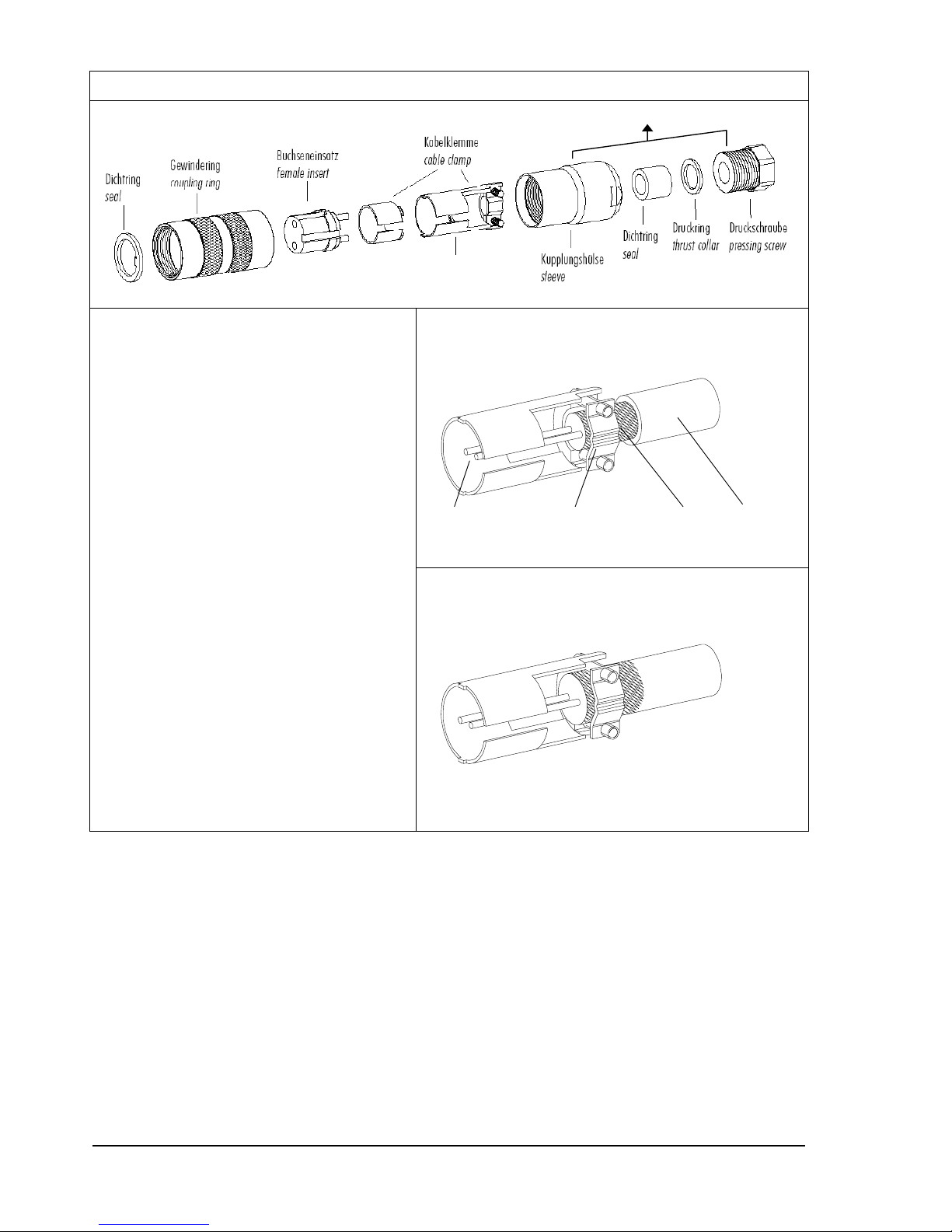
Coupling socket 507550 (Binder, series 432), EMC with cable clamp
View X
Cable strain relief
Cable assembly 1
1. String parts onto cable according to
diagram above.
2. Strip off cable sheath 20 mm
Shorten exposed shield by 15 mm
Strip off litz wire 5mm.
Cable assembly 1
Fit shrink tube or insulating tape
between litz wire and shield.
Cable assembly 2
Position shield to rear on
cable sheath if cable diameter
permits.
3. Solder litz wire to female insert,
position shield in cable clamp.
4. Screw on cable clamp.
5. Assemble other parts according to
diagram above.
6. Securely tighten cable strain relief
with spanner (AF16 and 17).
Cable assembly 2
View X
View X
Fig. 1: Connector assembly
4.3811.00.000_US-Anemometer-DSP_eng.doc 8 - 26 021511/10/06
Page 9

3.5 Connector pin assignment
Note:
- The exact functional assignment can be found in the supplementary sheet
"Factory Setting".
- Pins 1 to 6 (inclusive) are electrically isolated from the supply voltage
and the housing.
Pin No. Function Comment View of solder terminal
of coupling socket
1 Selection device ID (Low active), Bit 0 Pull up 1mA internal
2 Selection device ID (Low active), Bit 2 Pull up 10 KΩ internal
3 TX− / RX− (Z) RS 485 / RS 422 Serial interface
4 Selection device ID (Low active), Bit 1 Pull up 1mA internal
5 TX+ / RX+ (Y) RS 485 / RS 422 Serial interface
6 GND Serial interface
7 Supply 20−28 VAC, nom. 24 VAC No-load voltage 32 VAC
8 Supply 20−28 VAC, nom. 24 VAC No-load voltage 32 VAC
Shield
1
2
3
4
5
6
7
8
4 Maintenance
As the device does not have moving parts, i.e. is not subject to wear during operation, no servicing
is required.
Attention:
During storage, installation, de-installation, transport or
maintenance of the anemometer it must be ensured that no
water gets into the shaft or connector of the anemometer.
4.3811.00.000_US-Anemometer-DSP_eng.doc 9 - 26 021511/10/06
Page 10

4.3811.00.000_US-Anemometer-DSP_eng.doc 10 - 26 021511/10/06
5 Calibration
The ultrasonic anemometer does not contain any adjustable components such as electrical or
mechanical trimming elements. All components and materials used show invariant behaviour in
terms of time. This means that no regular calibration is required due to ageing. Errors in measured
values are only caused by mechanical deformation of the transformer arms and associated
changes in measurement path lengths.
The acoustic virtual temperature can be used to check the measurement path length. A change of
0.17% in the measurement path length and thus a measuring error of 0.17% for the wind velocity
corresponds to a deviation in the virtual temperature of 1 K at 20°C. With a 6 K temperature
deviation there is thus a measuring error of approx. 1% for the wind velocity.
Important:
Mechanical deformation of the measuring arms results in
errors in the measured values, which involve the output of
error telegrams / error signals to the analog interfaces.
In the event of any change in the measurement paths of the anemometer the manufacturer should
be consulted regarding recalibration.
6 Warranty
Damage caused by improper handling or external influences, e.g. lightning, do not fall under the
warranty provisions. The warranty entitlement expires if the device is opened.
Important:
The ultrasonic anemometer must be returned in the original
packaging as the warranty entitlement otherwise expires with
mechanical damage, e.g. deformation of measuring arms.
Page 11

4.3811.00.000_US-Anemometer-DSP_eng.doc 11 - 26 021511/10/06
7 Functional Description
The functioning of the ULTRASONIC anemometer is described below. Due to the internal structure
certain functions depend on other functions. Such dependency is described in each case. For
example, in half duplex mode independent telegram output is not permissible. There are also
restrictions regarding the functional definition of the cable connector. This is due to the double
assignment of individual PINs.
7.1 Serial communication
The ULTRASONIC provides an RS485 interface for serial communication. It can be operated either
in full or half duplex mode and at different baud rates.
A standard terminal program is used for communication with the ULTRASONIC. With a Windowsbased operating system Hyper Terminal is included in the scope of supply.
It has to be subsequently installed if required.
The ULTRASONIC does not contain any pull-up or pull-down resistors or a wave terminating
resistor.
When starting the ULTRASONIC, the communications parameters are output to the serial interface.
Output takes place at 9600.8N1. The baud rate, the duplex modus and the ID are output:
Example:
THIES ULTRASONIC
!00BR00006
!00DM00000
The ULTRASONIC starts with ID 0, a baud rate of 19200.8N1 and half duplex mode.
Page 12

4.3811.00.000_US-Anemometer-DSP_eng.doc 12 - 26 021511/10/06
7.1.1 General telegram structure
For serial communication the ULTRASONIC has a fixed telegram format which also permits
communication in bus mode. It has the following form:
NNBB<cr> <cr> stands for Carriage Return (Enter key)
for a data enquiry or
NNBBPPPPP<cr> <cr> stands for Carriage Return (Enter key)
for a parameter change.
The individual letters have the following meaning:
NN: Two-position ID of the ULTRASONIC. It can be selected in the range 00 to 99. The
presetting of the ID is '00'.
PPPPP: If a new parameter is to be set, the parameter is changed with a 5-position value. The
parameter is always right-justified; i.e. it thus has to be padded from the left with zeros.
Example:
Telegram No. 4 is to be interrogated. The relevant command is:
00TR00004<cr> <cr> stands for Carriage Return (Enter key)
The prerequisite is that the ULTRSONIC ID has the value '0'.
Example:
With the command
00BR<cr> <cr> stands for Carriage Return (Enter key)
the data record selected for the baud rate is returned.
!00BR00006
Note:
The input buffer of the ULTRASONIC can be emptied by transmitting Carriage
Return <CR>. If the ULTRASONIC possibly has invalid characters in the input
buffer, the input buffer can be processed by transmitting Carriage Return. In this
case it is recommended transmitting a Carriage Return at the beginning of a
telegram, e.g.:
<cr>00BR<cr> <cr> stands for Carriage Return (Enter key)
Page 13

4.3811.00.000_US-Anemometer-DSP_eng.doc 13 - 26 021511/10/06
7.1.2 Return values of ULTRASONIC
After a valid command has been input, the ULTRASONIC sends acknowledgement, e.g.
acceptance of the parameter or output of a data telegram.
For a standard command the response starts with a '!', followed by the ID and the parameter value.
If the input command is TR or TT, the ULTRASONIC transmits a data telegram as the response.
If the command cannot be processed for a certain reason, the device transmits a telegram with the
error code 'CE' (Command Error). The meanings of the values for CE are summarised in Table 1:
Return values with incorrect interpretation of command:
Value output in CE telegram Meaning
8
Incorrect access key
16
Parameter not in valid range
4 or 32
Violation regarding parameters of other commands
Table 1: Return values with incorrect interpretation of command
7.1.3 Access mode
For configuration the ULTRASONIC has a set of commands which determine behaviour in terms of
the propagation time. The commands are broken down into three levels:
• interrogation mode
• user mode
• configuration mode
Interrogation mode:
This mode includes commands which do not influence the parameters of the ULTRASONIC. They
include for example output of the system status and interrogation of the data telegram TR.
User mode:
This mode includes commands which alter the behaviour of the ULTRASONIC. These parameters
can be changed by the user. The system behaviour of the device is altered with these commands.
This group of commands includes e.g. settings for data transmission and averaging.
Configuration mode:
This mode includes commands which were set when adjustment of the device was performed at
the factory. They can be equated with calibration. These parameters must not be changed.
To distinguish between commands of the three groups when parameterising the ULTRASONIC the
device is equipped with an access key KY. Inputting of this key accesses the individual levels.
Access to commands at a higher level includes access to commands at a lower level.
Access key Response from ULTRASONIC Command level
00KY00000 WRITE PROTECTED
!00KY00000
Interrogation mode (preset)
00KY00001 USER ACCESS
!00KY00001
User mode
00KY00234 CONFIG ACCESS
!00KY00234
Configuration mode
Table 2: Access key for different command levels
Page 14

4.3811.00.000_US-Anemometer-DSP_eng.doc 14 - 26 021511/10/06
After the access key has been changed, the ULTRASONIC transmits a response which contains
not only the parameter input but also the access mode.
After parameters have been changed with the key '00001' or '00234', the ULTRASONIC must be
reset to the locked state with the command 00KY00000.
Example:
00KY00001
USER ACCESS Response from ULTRASONIC
!00KY00001 Response from ULTRASONIC
00AV00005 Change in averaging time
00KY00000
WRITE PROTECTED Response from ULTRASONIC
!00KY00000 Response from ULTRASONIC
7.1.4 Device ID
The device ID specifies the address to which the ULTRASONIC is to respond during serial
communication. The ID is determined on startup via the external signals at PIN 1, PIN 4 and PIN 2
(ADIO). The device ID lies in the range from 0..7. Every telegram from the ULTRASONIC starts
with the device ID. Under certain conditions this provides for bus mode, see 7.1.5 Bus mode.
On interrogation the device ID 99 is a generic ID. If this ID is used on interrogation, devices transmit
a response, regardless of the ID selected.
7.1.5 Bus mode
The concept of ID-based communication allows ULTRASONICs to be operated in a bus system.
In bus mode there are no restrictions on parameterisability and program upload. A station can also
be provided with a new program in bus mode for a specific purpose. With an update the program
update must be performed for every ULTRASONIC.
7.2 Data acquisition
The main function of the ULTRASONIC firmware is data acquisition and preparation. For data
acquisition sound impulses are transmitted by the sensors in a clockwise direction and received by
the sensor opposite. The propagation time measured is a measure of the velocity. A measuring
cycle is complete when every sensor has performed transmit and receive once. The complete data
record is then time-stamped and passed on to the next level. After the plausibility check the
individual components are calculated and written to the averaging buffer (see 7.2.1 Averaging).
For a resulting wind velocity < 0.1m/s the wind direction and wind velocity are set to zero. The wind
direction 0° is reserved for no wind. If the wind direction is equal to zero with WV > 0.1m/s, the
interface outputs 360°.
The last valid instantaneous value of the wind velocity is always used as the output value for this
criterion.
7.2.1 Averaging
Given the high data acquisition rate averaging is recommended in most cases. The averaging
period is set to 1 second with this device version.
It is a basic rule that only valid values are written to the averaging puffer. The size of the buffer is
not determined by the number of data records but by the difference in the time stamp between the
first and last data record. As a result any missing measured values do not influence the averaging
result. The content level of the averaging buffer is shown in the status value of the ULTRASONIC.
Page 15

4.3811.00.000_US-Anemometer-DSP_eng.doc 15 - 26 021511/10/06
The Ultrasonic incorporates two different practical procedures for averaging:
• one procedure for generating vectorial mean values
and
• one procedure for generating scalar mean values
"Vectorial averaging" is set in this device version.
7.3 Serial data output
The transmission of data via the RS485 interface is known as serial data output. Two modes are
available for data transmission:
• independent transmission of data
• transmission of data via interrogation telegram
This device version only transmits data on request.
7.3.1 Data enquiry
The command TR is used for data enquiry via the ULTRASONIC. The command has no access
protection. After processing the command the device sends back the appropriate response
telegram. The time between the last character in the request telegram and the first character in the
data telegram is < 0.5ms.
The response to a data enquiry is delayed by 5ms in this device version.
7.3.2 Fixed telegram formats
For telegram output several predefined telegrams are available for independent output and data
request.
The detailed structure is described in 10 Predefined Data Telegram. A reference list of telegram
formats can be found in Table 3: List of predefined data telegrams.
Telegram name Telegram number Telegram structure
VD
00001
(STX)gg.g ddd*cc(CR)(ETX)
VDT
00002
(STX)gg.g ddd ttt.t ss*cc(CR)(ETX)
V4DT 00003 (STX)ggg.g ddd ttt.t v ss*cc(CR)(ETX)
NMEA V 2.0 00004 $WIMWV,ddd.d,R,ggg.g,v,A*xx(CR)(LF)
Standard
deviation
00005
(STX)iigg.g hhh.h ddd eee ttt.t uuu.u ss*cc(CR)(ETX)
User-specific 00006 The user-specific telegram is output
Vx, Vy 00007 (STX)aaa.a;bbb.b;ttt.t;ss;cc(CR)(ETX)
VDT Version 1
(GAMESA)
00009 !iigggdddttttwf(CR)
Table 3: List of predefined data telegrams
Page 16

4.3811.00.000_US-Anemometer-DSP_eng.doc 16 - 26 021511/10/06
Where
g: wind velocity
h: standard deviation of wind velocity
d: wind direction
e: standard deviation of wind direction
t: temperature
u: standard deviation of temperature
s: status byte
c: check sum (EXOR link)
v: identifier for scaling of wind velocity (K, N, M, S = km/h, Knots, m/s, mph)
a: wind velocity in X-direction (east -> west)
b: wind velocity in Y-direction (north -> south)
w: status byte version 1
f: check sum version 1
i: device ID
7.4 Generation of check sum
The check sum is the result of the bytewise EXOR link of the bytes output in the telegram.
With the resulting check byte high and low nibble (4 bit) are EXOR linked and output as an ASCII
value.
7.5 Status information
7.5.1 Definition of status byte version 1
The status byte contains information about the current system status.
The information includes the occurrence of an error with the acquisition of measured values,
possible decalibration, e.g. caused by a change in the measurement path length due to deformation
of the measuring arms and the operating status of the device heating.
7.5.2 Structure of status byte version 1
Bit 0 0 = data valid 1 = data invalid
Bit 1 Temperature difference between X and Y measurement path (LSB)
Bit 2 Temperature difference between X and Y measurement path (MSB)
Bit 3 Averaging memory used (LSB)
Bit 4 Averaging memory used (MSB)
Bit 5 Measuring range exceeded (counter overflow)
Bit 6 Reserved (always one)
Bit 7 0 = heating off 1 = heating on
Page 17

4.3811.00.000_US-Anemometer-DSP_eng.doc 17 - 26 021511/10/06
7.5.3 Definition of temperature difference in status byte
Bit 2 Bit 1 Temperature difference x to y path in Kelvin
0 0
0.0 K to 3.1 K
0 1
3.2 K to 6.3 K
1 0
6.4 K to 7.9 K
1 1 ≥ 8.0 K → invalid measurement
7.5.4 Definition of averaging memory used
Bit 4 Bit 3 Averaging memory used
0 0 Averaging memory content level > 80%
0 1 Averaging memory content level > 66%
1 0 Averaging memory content level > 33%
1 1 Averaging memory empty
7.6 Behaviour in fault conditions
The ULTRASONIC is equipped with a highly effective internal fault detection and correction system.
This allows it to detect incorrect measured values using the history and to discard them.
It cannot however be ruled out that the ULTRASONIC will get into a situation in which the
acquisition of new data is impossible. In this case the error bits are set in the status values and a
defined value possibly output at the analog outputs.
It is a basic rule that the measured values output are always valid and can be interpreted by the
target system (unless a specific error telegram is output in the case of error). However, what may
happen in the case of error is that the data become 'too old', i.e. are not updated over a certain time
and freeze. In this case the error bits are set in the status byte. If a special error telegram is defined
with a serial telegram, this is output.
This device version outputs an error in the status byte if no new data can be determined for
approx.10 seconds.
7.7 Heating control
To prevent the device from freezing the ULTRASONIC is equipped with built-in heating for the
sensor arms. In standard mode the heating is controlled by the system status. If control of the
heating is software-set, the heating system will switch on under the following conditions:
Acoustic virtual temperature < 2°C
Continuous measuring error > 3sec
Page 18

4.3811.00.000_US-Anemometer-DSP_eng.doc 18 - 26 021511/10/06
The heating system switches off after another 10sec when:
Acoustic virtual temperature> 7°C
No error in acquisition of measured values
7.8 Output of all system parameters
Most parameters of the ULTRASONIC are stored internally in an EEPROM. The command SS can
be used to output all stored parameters.
Before amending parameters it is recommended making a backup copy of existing settings and
storing them in a text file.
7.9 Enquiry about software version
The command SV is used to enquire about the software version.
7.10 Forcing a restart
The command RS can be used to force a restart of the ULTRASONIC. The commands
00KY00001<cr>
00RS00001 <cr>
will restart the ULTRASONIC after approx. 3sec.
7.11 Bootloader
Whenever the ULTRASONIC is restarted, the device first starts a bootloader. The function of the
program is to start program upload. For this a specific program containing the new firmware must
be started at a connected PC. After identification the program upload then starts automatically. If
the bootloader does not know its remote station, the ULTRASONIC firmware starts.
7.12 Online Help
For a short description of commands the ULTRASONIC contains an Online Help which provides
information about individual commands. The Help text for the command is returned by inputting the
command and a '?'.
If the command
00?? <cr> <cr> stands for Carriage Return (Enter key)
is input, the ULTRASONIC will list all commands with the relevant Help.
Example:
Help with setting the baud rate is to be called up. With the command
00BR?<cr> <cr> stands for Carriage Return (Enter key)
the ULTRASONIC provides the following response:
BR: Set / get Baudrate
Page 19

4.3811.00.000_US-Anemometer-DSP_eng.doc 19 - 26 021511/10/06
0 -> reserved 10 -> 1200 7E1
1 -> reserved 11 -> 1200 7E1
2 -> 1200 8N1 12 -> 4800 7E1
3 -> 2400 8N1 13 -> 9600 7E1
4 -> 4800 8N1 14 -> 19200 7E1
5 -> 9600 8N1 15 -> 38400 7E1
6 -> 19200 8N1 16 -> 57600 7E1
7 -> 38400 8N1 17 ->115200 7E1
8 -> 57600 8N1
9 ->115200 8N1
8 Configuration of Ultrasonic Anemometer by Customer
The Ultrasonic Anemometer 2D is factory-set prior to delivery to the customer.
Setting is described in the supplementary sheet "Factory Setting".
It is possible for the customer to alter the factory setting of the Ultrasonic Anemometer 2D or to
adapt it to new requirements. Here it should be borne in mind that with a change in settings, the
order number allocated at the factory can then no longer help with identification.
These Operating Instructions relate to the device version 4.3811.00.000.
For the adjustment of settings we recommend you consult the General Operating Instructions for
THIES ULTRASONIC. This describes all available settings.
Recommendation:
After performing configuration please amend the supplementary sheet "Factory Setting" and send
in to the manufacturer in the event of maintenance or repair.
Page 20

4.3811.00.000_US-Anemometer-DSP_eng.doc 20 - 26 021511/10/06
9 Command List, Short
Command Description
<id>AA<para5>
Functions for PIN WV/RXD-(Analog channel A)
<id>AB<para5>
Functions for PIN WD/RXD+ (Analog channel B)
<id>AC<para5>
Functions for PIN ADIO (Analog channel C)
<id>AM<para5>
Selection of averaging method (Average mode)
<id>AN<para5>
Analog output mode (Analog output)
<id>AO<para5>
Scaling of analog wind direction output (Angle output)
<id>AR<para5>
Scaling of analog wind velocity output (Analog range)
<id>AT<para5>
Testing of analog inputs/outputs (Analog test)
<id>AV<para5>
Averaging time (Average)
<id>AU<para5>
Update of analog inputs
<id>AY<para5>
Scaling of minimum value for analog input PIN WV/RXD-
<id>AZ<para5>
Scaling of maximum value for analog input PIN WV/RXD-
<id>BH<para5>
Selects the Bavaria Hesse measuring instrument addresses
<id>BR<para5>
Select baud rate (Baud rate)
<id>BX<para5>
Select baud rate (Baud rate extension)
<id>BY<para5>
Scaling of minimum value for analog input PIN WV/RXD+
<id>BZ<para5>
Scaling of maximum value for analog input PIN WV/RXD+
<id>CI<para5>
Selects command interpreter (Command interpreter)
<id>CY<para5>
Scaling of minimum value for analog input PIN ADIO
<id>CZ<para5>
Scaling of maximum value for analog input PIN ADIO
<id>DA<para5>
Data request in Bavaria Hesse command interpreter
<id>DE<para5>
Standard deviation (Deviation)
<id>DF<para5>
Set initial values (Default values)
<id>DM<para5>
Duplex mode
<id>EI<para5>
Analog value in case of error (Error inversion)
<id>FB<para5>
Fast boot
<id>HT<para5>
Heating control (Heating)
<id>ID<para5>
ULTRASONIC ID
<id>KY<para5>
Access mode (Key)
<id>MA>>para5>
Automatic adjustment of measured value acquisition (Measurement automation)
<id>MD>>para5>
Measuring interval (Measurement delay)
Page 21

4.3811.00.000_US-Anemometer-DSP_eng.doc 21 - 26 021511/10/06
<id>NC<para5>
Correction to north (North correction)
<id>OD<para5> Emulation of an ULTRASONIC 1D (One dimension)
<id>OR<para5>
Telegram output interval (Output ratio)
<id>OS<para5>
Scaling of wind velocity output (Output scale)
<id>PC<para5>
Plausibility test (Plausibility check)
<id>PR<para5>
Periodic receive time (Receive time)
<id>PT<para5>
Periodic send time (Period transmit time)
<id>RD<para5>
Delayed response (Response delay)
<id>RS<para5>
Restart ULTRASONIC (Reset)
<id>SH<para5>
Serial number (High Word) (Serial number high word)
<id>SH<para5>
Serial number (Low Word) (Serial number low word)
<id>SC<para5>
Minimum value of analog outputs (Start current)
<id>SS<para5>
System status (System status)
<id>SV<para5>
Software version (Software version)
<id>TC<para5> TC Temperature correction (Temperature correction)
<id>TE<para5> Propagation time delay East sensor (Sensor delay EAST sensor)
<id>TN<para5> Propagation time delay North sensor (Sensor delay NORTH sensor)
<id>TR<para5> Telegram request (Transmit request)
<id>TT<para5> Independent telegram output (Transmit telegram)
<id>TS<para5> Propagation time delay South sensor (Sensor delay SOUTH sensor )
<id>TW<para5> Propagation time delay West sensor (Sensor delay WEST sensor)
<id>UA<para5>
Addition of definitions to user-defined telegram (Add user telegram item)
<id>UR<para5>
Deletion of one or more definitions at the end of the user-defined telegram (Remove
user telegram item)
<id>US<para5>
Save user-specific telegram definition (User telegram save)
<id>UT<para5>
User-specific telegram (User telegram)
<id>VC<para5>
Constant velocity correction (Velocity correction)
<id>VT<para5>
Angle-dependent velocity correction (Velocity table)
<id>XI<para5>
External ID (External ID)
Page 22

4.3811.00.000_US-Anemometer-DSP_eng.doc 22 - 26 021511/10/06
10 Predefined Data Telegram
Wind velocity, direction, acoustic virtual temperature, status and check sum
Command: TR00009
Telegram structure "Gamesa" : !iivvvdddttttwfR
Ch. No. Character set Function
1 (!) ! Response character
2 (i) 0 ••• 9 Identifier
3 (i) 0 ••• 9 Identifier
4 (v) 0 ••• 9 Wind velocity * 10 1m/s
5 (v) 0 ••• 9 Wind velocity * 10 0m/s
6 (v) 0 ••• 9 Wind velocity * 10
-1
m/s
7 (d) 0 ••• 9 Wind direction * 10 2 degree
8 (d) 0 ••• 9 Wind direction * 10 1 degree
9 (d) 0 ••• 9 Wind direction * 10 0 degree
10 (t) + ••• − Leading sign
11 (t) 0 ••• 9 Temperature * 10 1 °C
12 (t) 0 ••• 9 Temperature * 10 0 °C
13 (t) 0 ••• 9 Temperature * 10
-1
°C
14 (w) ASCII Status byte, see item 6.2.2
15 (f) ASCII Check sum, see item 6.2.1
16 (R) 0D HEX Carriage Return
Page 23

4.3811.00.000_US-Anemometer-DSP_eng.doc 23 - 26 021511/10/06
11 Technical Data
Wind velocity Measuring range 0...65 m/s
Scaling of analog output freely selectable
<= 5 m/s: ± 0.1 m/s (rms, mean over 360°) Accuracy
> 5 m/s: ± 2% of measured value (rms, mean
over 360°)
0.1 m/s: in telegrams 14.1 to 14.6 Resolution
<0.1 m/s: in telegrams 14.7 and user-defined
telegrams
Wind direction Measuring range 0...360°
0...360° , 0... 540°, 0..720° for analog output,
adjustable
Accuracy ± 1.0°
1°: in telegrams 14.1 to 14.6 Resolution
< 1°: in telegrams 14.7 and user-defined
telegrams
Virtual temperature Measuring range - 40 .... + 70 °C
Accuracy ± 0.5 K
Resolution 0.1 K (in telegrams 14.1 to 14.6)
Data output
digital
Interface RS 485 / RS 422
Baud rate 1200, 2400, 4800, 9600, 19200, 38400, 57600,
115200, 230400, 460800, 921600 adjustable
Output
Instantaneous values, wind velocity, wind direction
and virtual temperature
Sliding mean values 0.5sec.. 100min freely
selectable
Standard deviation for wind velocity, wind direction
and virtual temperature.
Predefined data telegrams or user-defined data
telegram.
Output rate 1 per 1msec to 1 per 60 seconds adjustable
Status identification Heating, failure of measurement path, ∆T path
temperatures
Data output
analog
Electr. outputs 0 ... 20 mA / 0... 10 V or 4... 20 mA / 2... 10 V
only wind velocity, wind direction and acoustic
virtual temperature
Burden on current output maximum 400Ω
Burden on current output minimum 4000Ω
Page 24

4.3811.00.000_US-Anemometer-DSP_eng.doc 24 - 26 021511/10/06
Output
Instantaneous values
Sliding mean values 0.5sec..100min freely
selectable
Output rate Updating rate 1 per 100 msec
Resolution 16 bit
General Internal measuring
rate
Up to 1500 measurements per second at 25 °C
Bus mode Bus mode with up to 98 devices possible
Program update Program update possible in bus mode
Temperature range Operating temp. - 40... + 70 °C
Storage -50... +80°C
Operating voltage Supply electronics, 12... 28 V AC/DC +-10%;
approx. 2 VA
Supply heating, 24 V AC/DC +-15%; max. 28V; typ.
80 VA @ 24V
Protection type IP 65 (with proper installation, see section
"Preparation for operation")
Icing-up as per THIES STD 012001
EMC EN 55022 5/95 class B; EN 50082-2 2/96
Model V4A stainless steel for housing and transformer
arms
Installation type Mast tube 1½ ", e.g. DIN 2441
Connection type 8-pole plug connection in shaft
Weight 2.5 kg
Page 25

12 Dimension Drawing
Take-up for mast tube 1
1/2“
40mm deep
275
200
422
Ø70
8-pole con-
nector in shaft
13 Accessories (available as optional features)
Connecting cable, complete 507751 15 m cable with coupling socket on
transmitter side. The other end of the cable
is equipped with core identification rings.
PC-Program Meteo-Online 9.1700.98.000 For graphical display of measured values on
a PC
Power supply unit 9.3388.00.000 For power supply to the ultrasonic
anemometer
Lightning rod 4.3100.99.150 As lightning protection
4.3811.00.000_US-Anemometer-DSP_eng.doc 25 - 26 021511/10/06
Page 26

ADOLF THIES GmbH & Co. KG
Hauptstraße 76 37083 Göttingen Germany
P.O. Box 3536 + 3541 37025 Göttingen
Phone ++551 79001-0 Fax ++551 79001-65
www.thiesclima.com info
@
thiesclima.com
- Alterations reserved -
4.3811.00.000_US-Anemometer-DSP_eng.doc 26 - 26 021511/10/06
 Loading...