

THIEMAN TVLR 125, TVLR 16, TVLR 20, TVLR 30 Installation Instructions Manual
TVLR
HIEMAN
N
T
E
A
THE ASSOCIATION FOR THE WORK TRUCK INDUSTRY
TM
MEMBER
Railgates By THIEMAN
SERIES
TVLR 125, 16, 20, 30
INSTALLATION INSTRUCTIONS
!
IMPORTANT! KEEP IN VEHICLE!
PLEASE READ AND UNDERSTAND THE CONTENTS OF THIS
MANUAL BEFORE OPERATING THE EQUIPMENT.
Phone: 419-586-7727 Fax: 419-586-9724
TAILGATES, INC.
600 East Wayne Street
Celina, Ohio 45822

ATTENTION INSTALLERS:
Changes are made periodically to the installation procedure to comply with engineering
changes. To ensure proper liftgate operation, it is VERY IMPORTANT to read and understand
the installation instructions before attempting an installation. Installers also MUST read and
understand the liftgate’s Owner’s Manual before installing the liftgate, so they can operate the
liftgate safely as required during different stages of the installation process. NEVER perform a
modification on the liftgate, which is not specifically covered in this manual or which is
unauthorized by Thieman. Modifications may result in failure of the liftgate and may create
hazards for liftgate installers, operators, or maintainers. Serious damage, equipment failure, or
operator injury could result from improper installation. This equipment MUST have all decals
applied properly. FAILURE to apply all decals properly will VOID all warranties! Any installer
with questions or doubts should contact Thieman before proceeding.
NOTES:
1. All maximum mounting dimensions are shown with the vehicle empty; all minimum mounting
dimensions are shown with the vehicle loaded.
2. Check the bed height when vehicle is parked on a level surface.
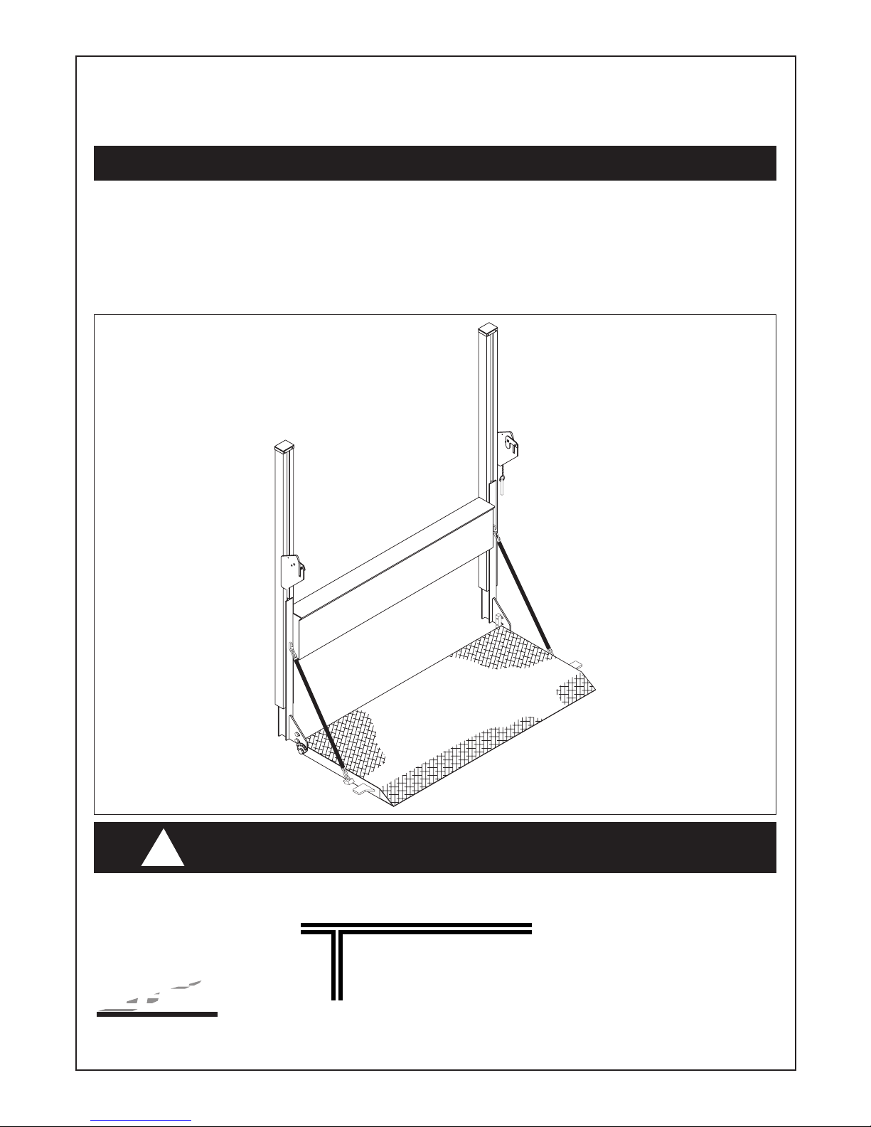
3. Refer to figure 1 and table 1 for overall dimensions of liftgates and bed height ranges for
different models.
4. The TVLR series railgates are all level ride, which means when the vehicle is located on a
level surface, the rails should be perpendicular to the ground. When mounting, consideration
should be given to the platform position with the truck both empty and loaded. See figure 2
and 3.
TVLR 125/16/20/30
MODEL TYPE RAIL HEIGHT "A" FRAME WIDTH "B" BED HEIGHT ABOVE BED RANGE
RANGE
STANDARD 85 80 33-54 NA
STANDARD 85 90, 95, 100 33-56 NA
ABOVE BED 89 80
41-44 15-10
ABOVE BED 89 90, 95, 100
41-46 15-10
LOW BED 83 80 33-40 16-14
LOW BED 83 90, 95, 100 33-40 16
33-40 16-14
33-40 16
Table 1.
NOTES:
1. All bed height ranges shown in table 1 allow installer to provide a minimum of 18" of ground
clearance by cutting off the lower end of the rail as needed unless otherwise stated. Rails
must NOT be cut more than 25" above the ground (Note: 25” measurement must be made
with truck unloaded. See Step 12 of Installation Instructions. On special orders, consult
factory as the allowable trim dimensions may vary from what is shown here).
2. Optional light covers in which the lights are below the cylinder housing will not allow the total
18" inches of ground clearance on standard bed models in the bed height range of 33-36".
2.
INSTALLATION INSTRUCTIONS
Step 1 Inspect entire package of your new liftgate for obvious damage. Report any damage to
the freight line who delivered your liftgate. DO NOT REMOVE ANY BANDING!
Step 2 Locate the vehicle on which the liftgate is to be mounted on a dry and level floor and
open the rear door on the vehicle.
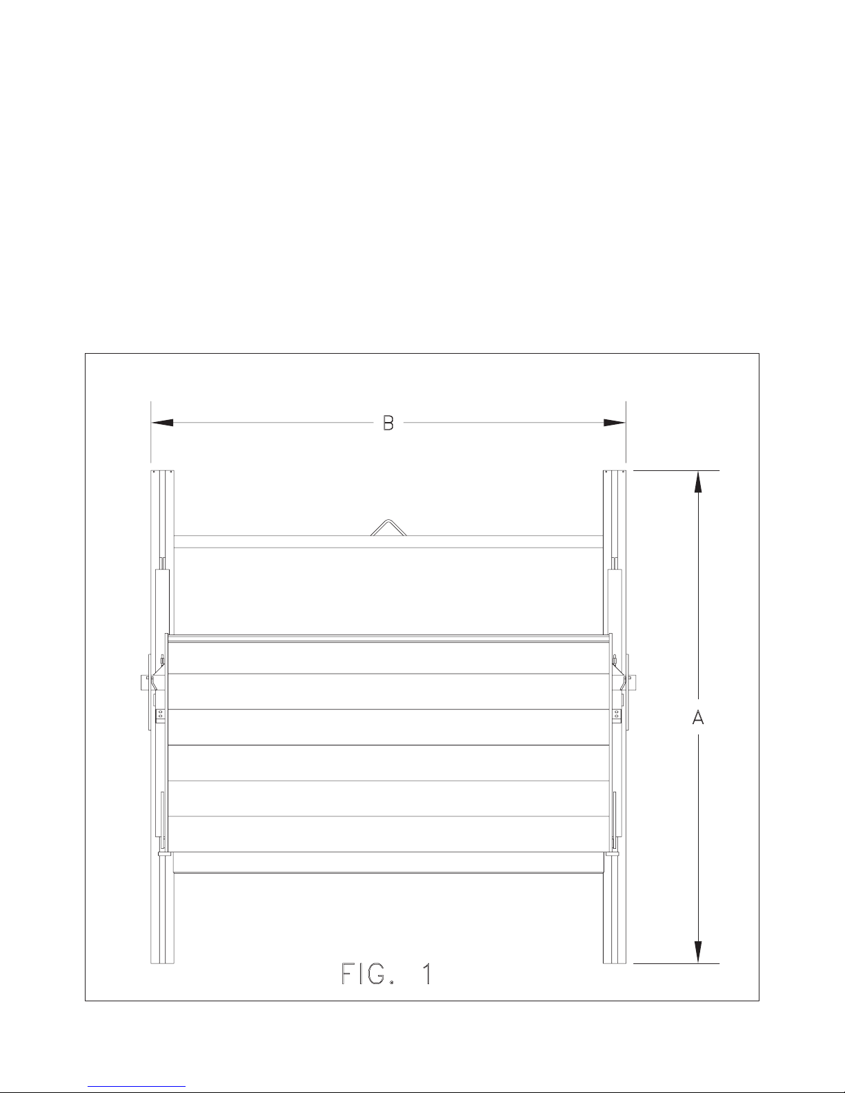
Step 3 Raise gate and place it against the rear of the vehicle and remove any obstructions
where possible. If obstruction can not be removed, use 4 spacers 12" long x 3" wide by
depth of interference and weld to top and bottom of rails. See figure 2. (If structural
angle or tubing is used for spacer, it must have a .25" minimum wall thickness). The
depth of the spacers may vary from top to bottom to enable a perpendicular mounting
to the ground. See figure 3.
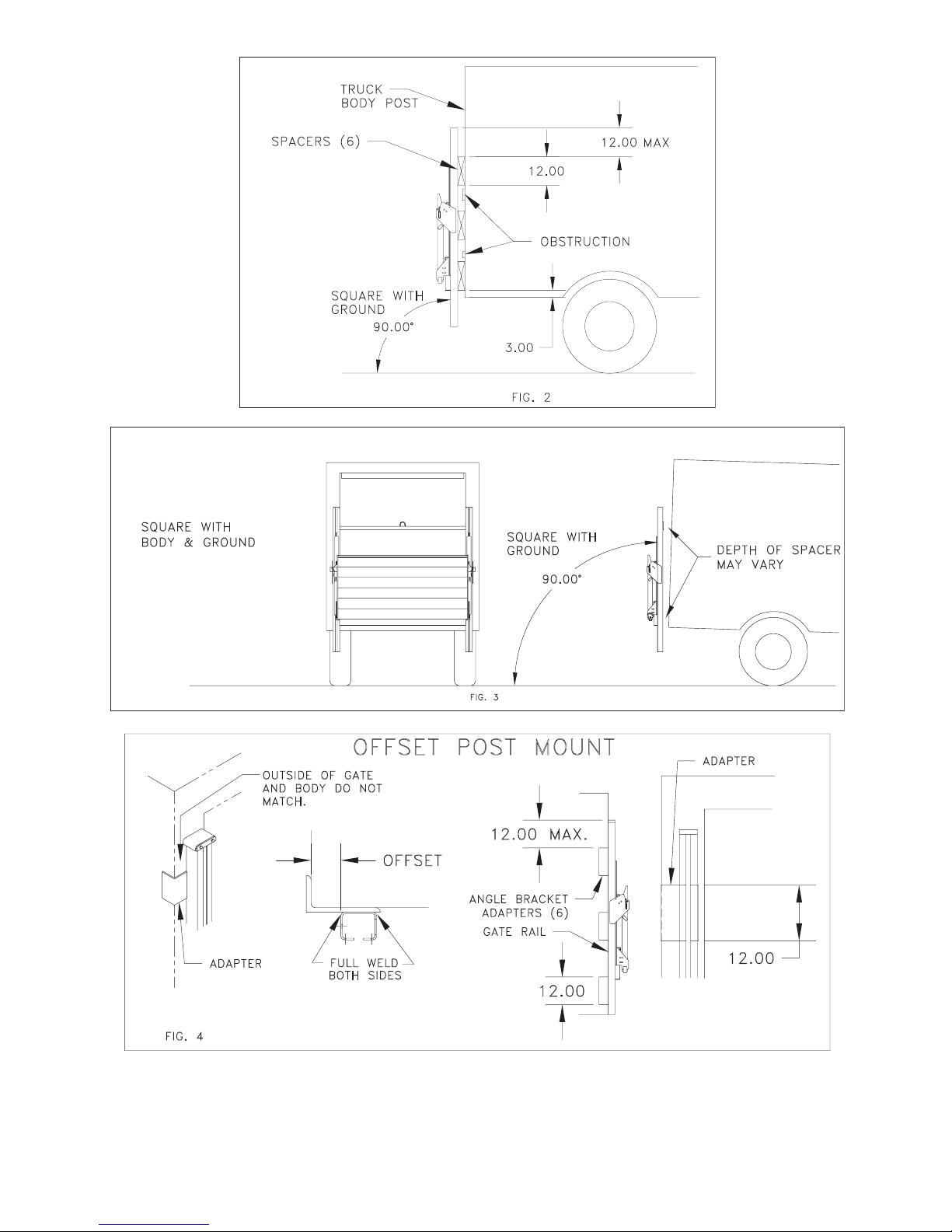
Step 4 If the gate width does not match the width of the vehicle body, fabricate 4 adapters .25"
minimum wall thickness x 12" long. Weld adapters to the back side of liftgate's rails to
match location of body's rear corner posts as shown in figure 4.
3.
Step 5 If the truck's rear corner posts are aluminum, four steel angle brackets .25" minimum
wall thickness x 12" must be fabricated and attached as shown in figure 5. Bolt
brackets to rear of vehicle as required to support the load.
4.
 Loading...