

STOW
HIEMAN
N
TE
A
THE ASSOCIATION FOR THE WORK TRUCK INDUSTRY
TM
MEMBER
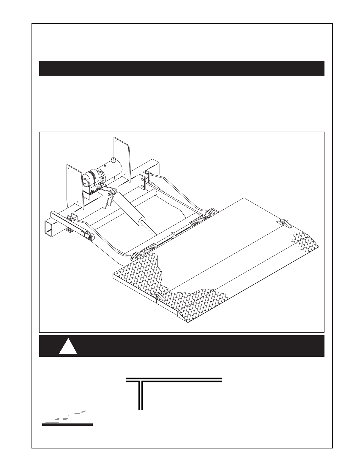
Tailgates By THIEMAN
AWAY
M, MLB, MDC, MDC LB
INSTALLATION INSTRUCTIONS
!
IMPORTANT! KEEP IN VEHICLE!
PLEASE READ AND UNDERSTAND THE CONTENTS OF THIS
MANUAL BEFORE OPERATING THE EQUIPMENT.
Phone: 419-586-7727 Fax: 419-586-9724
M-25 shown
TAILGATES, INC.
600 East Wayne Street
Celina, Ohio 45822
www.thiemantailgates.com

16, 20, 25, 30
M
ATTENTION INSTALLERS:
hanges are made periodically to the installation procedure to comply with engineering changes. To
C
ensure proper liftgate operation, it is VERY IMPORTANT
to read and understand the installation
instructions before attempting an installation. Installers also MUST read and understand the liftgate’s
Owner’s Manual before installing the liftgate, so they can operate the liftgate safely as required during
different stages of the installation process. NEVER perform a modification on the liftgate, which is not
specifically covered in the manual or which is unauthorized by Thieman. Modifications may result in
failure of the liftgate and may create hazards for liftgate installers, operators, or maintainers. Serious
damage, equipment failure, or operator injury could result from improper installation. This equipment
MUST have all decals applied properly. FAILURE to apply all decals properly will VOID all warranties!
Any installer with questions or doubts should contact Thieman before proceeding.
The M, MLB, MDC, and MDCLB are stow-away style liftgates for use on trucks and trailers. Before
mounting your liftgate, make sure that the model you have will work on the truck or trailer you intend to
mount it on. The loaded and unloaded bed height of your truck (with weight of liftgate figured in) MUST
fall within the bed height range of your liftgate. To determine the bed height range of your liftgate, you
must know the full model name, the platform material of both the main section and extension (i.e. both
steel, both aluminum, or steel main with aluminum extension), and the platform size (see charts and figures on pages 2 thru 4).
NOTES:
1. The tip of the platform will touch the ground on standard STOW-AWAY liftgates, but not on gates
designed for “level ride”. “Ramp ride” is standard, “level ride” is built for special order only.
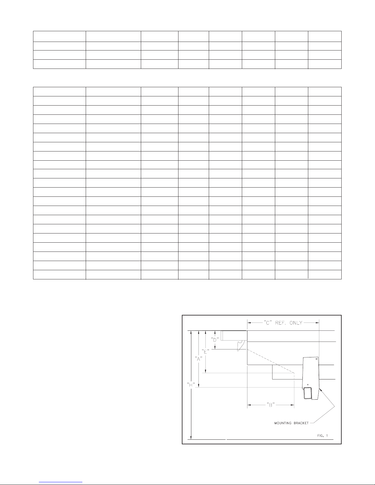
2. Reference figures 1 and 2 for charted dimensions on pages 2 thru 4.
3. All maximum mounting dimensions are shown with the vehicle empty; all minimum mounting dimensions are shown with the vehicle loaded.
4. Check bed height “H” when parked on a level surface.
5. Check “C” dimension for possible interference with spring hanger bracket before installation.
6. If the liftgate was ordered with the optional 216 receiver kit, use the loaded bed height (Hmin) to
determine what set of mounting dimensions to use. Bed height range for 216 Kit is 42" min. (vehicle
fully loaded) and 54" max. (vehicle empty).
ALL STEEL PLATFORMS (STEEL MAIN AND EXTENSION)
Platform Size Models H A B C D E
32+5 All Models 34"-40" 16.50 14.00 32.00 4.00 5.50
38W MLB 16/20 34"-40" 16.50 14.00 32.00 4.00 5.50
36+6 M 16/20 37"-44.99" 19.50 17.00 30.50 5.00 8.00
45"-50" 22.00 16.00 28.50 5.50 10.00
50"-54" 25.00 15.00 25.50 6.50 13.00
36+6 M 25/30 38"-44.99" 19.50 17.00 30.50 5.00 8.00
45"-50" 22.00 16.00 28.50 5.50 10.00
50"-54" 25.00 15.00 25.50 6.50 13.00
42+6 All Models 42"-45" 19.50 18.50 30.50 5.00 8.00
45"-50" 22.00 17.50 28.50 5.50 10.00
50"-54" 25.00 16.50 25.50 6.50 13.00
42+10 RET M 16/20 37"-45" 19.50 17.00 30.50 4.19 6.00
45"-50" 22.00 16.50 28.50 4.75 8.00
50"-54" 25.00 16.00 25.50 5.50 11.00
42+10 RET M/MDC 25/30 38"-45" 19.50 17.00 30.50 4.19 6.00
45"-50" 22.00 16.50 28.50 4.75 8.00
50"-54" 25.00 16.00 25.50 5.50 11.00
42W All Models 45"-50" 22.00 16.00 28.50 5.50 10.00
50"-54" 25.00 15.00 25.50 6.50 13.00
2.
STEEL MAIN SECTION/ALUMINUM EXTENSION PLATFORMS
Platform Size Models H A B C D E
48W M/MDC25 45"-49.99" 22.00 17.00 28.50 5.50 10.00
50"-54" 25.00 15.00 25.50 6.50 13.00
48W MDCLB 25 38"-45" 19.50 17.00 30.50 5.00 8.00
ALL ALUMINUM PLATFORMS (ALUMINUM MAIN AND EXTENSION)
Platform Size Models H A B C D E
27+6 MLB 16/20/25 34"-40" 16.50 13.00 32.00 4.50 5.50
37W MLB 16/20 34"-40" 16.50 13.00 32.00 4.50 5.50
36+6 M16/20 37"-44.99" 19.50 18.00 30.50 5.00 8.00
45"-50" 22.00 17.00 28.50 5.50 10.00
50"-54" 25.00 16.00 25.75 6.50 13.00
36+6 MDC/M25/30 38"-44.99" 19.50 19.00 30.50 5.00 8.00
45"-50" 22.00 18.00 28.50 5.50 10.00
50"-54" 25.00 16.50 25.75 6.50 13.00
40+6 All Models 42"-45" 19.50 19.00 30.50 5.00 8.00
45"-50" 22.00 18.00 28.75 5.50 10.00
50"-54" 25.00 16.50 26.00 6.50 13.00
42+10 RET M 16/20 37"-44.99" 19.50 19.00 30.50 4.50 6.50
45"-50" 22.00 18.00 28.50 5.00 8.50
50"-54" 25.00 16.50 25.75 6.00 11.50
42+10 RET M/MDC 25/30 38"-44.99" 19.50 19.00 30.50 4.50 6.50
45"-50" 22.00 18.00 28.50 5.00 8.50
50"-54" 25.00 16.50 25.75 6.00 11.50
48W M/MDC25 45"-49.99" 22.00 18.00 28.50 5.50 10.00
50"-54" 25.00 16.25 25.75 6.50 13.00
48W MDCLB25 39"-45" 19.50 19.00 30.50 5.00 8.00
A—Distance from top of bed to trunnion
tube.
B, D, E—Clearance needed for platform in
closed position.
C—Minimum distance needed for
mounting plates.
F, G, J, K—Rubrail notch dimension. See
figure 2.
H—Distance from ground to bed height.
3.

INSTALLATION INSTRUCTIONS
Step 1 Remove banding from gate undercarriage. Inspect for obvious shipping damage or
missing parts.
Step 2 If necessary notch rear of body as shown in figure 2.
Step 3 Center and level spacer at rear of body and tack weld into position. See figure 3.
4.
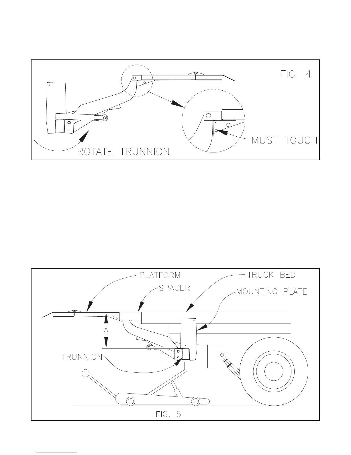
Step 4 Raise the liftgate by lifting under the main section of the folded platform with a forklift.
Make sure the platform is clamped securely to the forks. With the trunnion and liftarms
hanging from the platform, the platform rib and pivot assembly should make firm contact.
The installer may need to rotate the trunnion, as shown, to make this contact. Tack weld
the platform hinge to the pivot assembly to maintain contact. See figure 4.
Step 5 Using a forklift or crane, center and position liftgate behind vehicle and jack trunnion into
position. See figure 5 and 1 for “A” dimension. Note: Do Not connect hydraulic lines at
this time, the M series liftgates are pre-assembled with cylinder and pump mounted. On
certain installations, for instance a truck with a rear fuel tank, the pump may get in the
way of obtaining the proper “A” dimension. In most of these cases, Except for the 50" to
54" bed height range, where the “A” dimension is 25.00, the pump may be removed and
then mounted to the second, more rearward, set of holes in the pump mounting bracket
to provide more clearance. Note: Do Not move pump when the “A” dimension is 25.00
because the platform will not stow properly.
Step 6 Cut a small post or similar item to the correct length and place it under the platform so
the platform and payload area are at the same height. Place barrels or other protective
equipment under the platform so that the gate will not accidentally fall and injure someone.
5.

Step 7 Attach mounting plates to truck by means of .62" Grade 8 screws or by a .38 fillet
weld all around. Weld the mounting plates to the trunnion tube all around in the same
manner.
Note: On installation where narrow underframe members are used, the liftgate mounting
plates will reach these frame members for mounting purposes; however, the space
between the frame members and trunnion now becomes quite large. This lengthy
unsupported area may contribute to undesirable ‘springiness’ under heavy loading.
Many installers when faced with this problem extend the underframe support on the
mounting plate closer to the trunnion by adding a channel section under the existing
frame member as shown in figure 6. On certain equipment such as a lengthened van
body, rebuilt trailer or other altered vehicle, where the underframe stops short of the
end of the vehicle body frame, extra support must be added to avoid any independent deflection. See figure 7 for bracing suggestions. Refer to figure 1 for clearances.
Step 8 Fasten the 150 amp circuit breaker provided within 2 ft. of the truck battery. Route the
battery cable from the liftgate toward the circuit breaker. AVOID SHARP CORNERS
AND HIGH HEAT AREAS. Use cable clips provided to secure the cable to the truck
frame every 2 ft. Cut the cable to the desired Length and strip .88" of the insulation
from the end. Slide the pre-cut heat shrink over the end of the cable. Secure the
cable lug in a vise and apply heat to the connector and insert the cable as the solder
melts. Allow connector to cool and install the heat shrink. Attach this end to one terminal on the 150 amp circuit breaker.
6.

Step 9 Many late model trucks have battery connections as shown in figure 8. The ground
cable from the battery may be connected directly to the engine block with only a light
braided ground strap connecting the block to the chassis. Where this is the case, the
factory installed cable does not provide an adequate ground circuit for operating battery powered liftgates. We recommend that the cables labeled with an “X” be not less
than #2 gauge cable as supplied in the installation kit. Also because of the high current draw (approximately 200A)we recommend that the alternator be a heavy duty
type and the battery must have a 150 AMP minimum reserve capacity.
7.

Step 10 Install breather cap on power unit and connect hydraulic hose from power unit to flow
control. Remove tack weld from Step 4. See figures 9 thru 12 for hose and battery
cable connections. On Gravity Down
liftgates, install return line in place of plugs
on butt end of cylinder and return port on pump reservoir. On Power Down
liftgates, the rod end port on cylinder must be plumbed to C1 port on pump.
(Note: Incorrectly plumbing rod end port on cylinder to C2 port will make gate drift
down and motor to spin backwards from raised position.) Attach ground cable to the
tapped hole in the pump base labeled “GND” and to the trunnion mounting plate with
the .38 hardware and internal lockwashers provided.
Step 11 Locate and mount the toggle switch assembly or pushbutton box in a convenient
place and wire the switch according to figure 13 or 14.
8.

9.

Step 12 Check all operations and trim excess where required for stow clearances. The M
series liftgate comes with a standard snubber kit to prevent excessive wear during
transport. See figure 15 for mounting instructions.
Step 13 To re-adjust the platforms spring assist, follow these steps:(See figure 16.)
1. Fold the platform for stowing and raise until the tension is relieved from spring
item C.
2. Remove snap ring item A from the groove and slide it to the left.
3. Remove the locknut item G from item E.
4. Slide spring support tube item B to the left and tilt right side up and remove from
assembly.
5. Remove long straight end of closing spring from hole in center rib of platform item
D. Moving the spring to the left decreases the tension and to the right increases
the tension.
6. Return spring support tube to position and replace snap ring.
10.

Step 14 After installation is complete lower platform to the ground and if a sag is present
between the platform and main section a shim must be added as shown in figure 17.
11.

Step 15 Now review the entire installation with the power source disconnected. With the
power connected again, check for possible interference of all moving parts. If interference occurs review the instructions and contact THIEMAN if the problem can not
be eliminated.
Step 16 Thieman recommends that the installer perform a weight test of the liftgate to check
the welds or mounting bolts and the structural integrity of the body or frame of the
truck or trailer. The load used should be the maximum weight rating of the particular
liftgate with the weight centrally located on the platform. A minimum of 20 cycles
should be made to insure the integrity of the mounting.
Step 17 Finish paint as required and remove the pre-mask on decals already applied by
Thieman. Apply the remaining decals in the appropriate locations as shown. When
painting, carefully grease or mask fittings and exposed portion of the piston rod. The
decals MUST be applied properly or all warranties are VOID!
Step 18 Any lights that were removed or obstructed must be replaced or relocated in such a
manner that the completed vehicle must be compliance with FMVSS 108 (49 CFR
571.108).
Step 19 It may be necessary to add Rear End Protection on this installation. Check your local
and state laws for requirements for FMCSR 49 CFR 393.86.
12.

Item Part Name Part Number
1 Warning Decal-off center 4671050
2 Fast Idle Decal 4650150
2 PTODecal 4650140
3 Danger Decal-no riding 4609
4 Operating Decal 4650890
5 Capacity Decal-1600# 4650750
5 Capacity Decal-2000# 4650100
5 Capacity Decal-2500# 4650110
5 Capacity Decal-3000# 4650120
6 Warning Decal-pinch point 4604
7 Handle Decal 4605
8 Thieman Nameplate (not shown) 4650800
9 Urgent Warning Decal 4681
10 Reflector (3) 5705
11 Wiring Diagram-Gravity Down 4612
11 Wiring Diagram-Power Down 4614
12 Warning Decal 4620
13 Caution Decal 4650770
14 Receiver Latch Decal (w/optional 216 Kit) 4683
13.

14.

15.

Rev. 12/17 • 5C • MP94438
 Loading...