

THIEMAN trailgates M, MDC LB, MLB Installation Instructions Manual
STOW
HIEMAN
N
TE
A
THE ASSOCIATION FOR THE WORK TRUCK INDUSTRY
TM
MEMBER
Tailgates By THIEMAN
AWAY
M, MLB, MDC, MDC LB
INSTALLATION INSTRUCTIONS
!
IMPORTANT! KEEP IN VEHICLE!
PLEASE READ AND UNDERSTAND THE CONTENTS OF THIS
MANUAL BEFORE OPERATING THE EQUIPMENT.
Phone: 419-586-7727 Fax: 419-586-9724
M-25 shown
TAILGATES, INC.
600 East Wayne Street
Celina, Ohio 45822
www.thiemantailgates.com

16, 20, 25, 30
M
ATTENTION INSTALLERS:
hanges are made periodically to the installation procedure to comply with engineering changes. To
C
ensure proper liftgate operation, it is VERY IMPORTANT
to read and understand the installation
instructions before attempting an installation. Installers also MUST read and understand the liftgate’s
Owner’s Manual before installing the liftgate, so they can operate the liftgate safely as required during
different stages of the installation process. NEVER perform a modification on the liftgate, which is not
specifically covered in the manual or which is unauthorized by Thieman. Modifications may result in
failure of the liftgate and may create hazards for liftgate installers, operators, or maintainers. Serious
damage, equipment failure, or operator injury could result from improper installation. This equipment
MUST have all decals applied properly. FAILURE to apply all decals properly will VOID all warranties!
Any installer with questions or doubts should contact Thieman before proceeding.
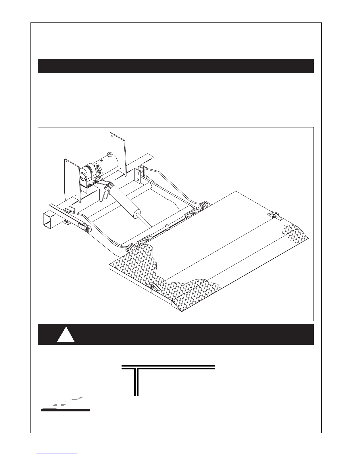
The M, MLB, MDC, and MDCLB are stow-away style liftgates for use on trucks and trailers. Before
mounting your liftgate, make sure that the model you have will work on the truck or trailer you intend to
mount it on. The loaded and unloaded bed height of your truck (with weight of liftgate figured in) MUST
fall within the bed height range of your liftgate. To determine the bed height range of your liftgate, you
must know the full model name, the platform material of both the main section and extension (i.e. both
steel, both aluminum, or steel main with aluminum extension), and the platform size (see charts and figures on pages 2 thru 4).
NOTES:
1. The tip of the platform will touch the ground on standard STOW-AWAY liftgates, but not on gates
designed for “level ride”. “Ramp ride” is standard, “level ride” is built for special order only.
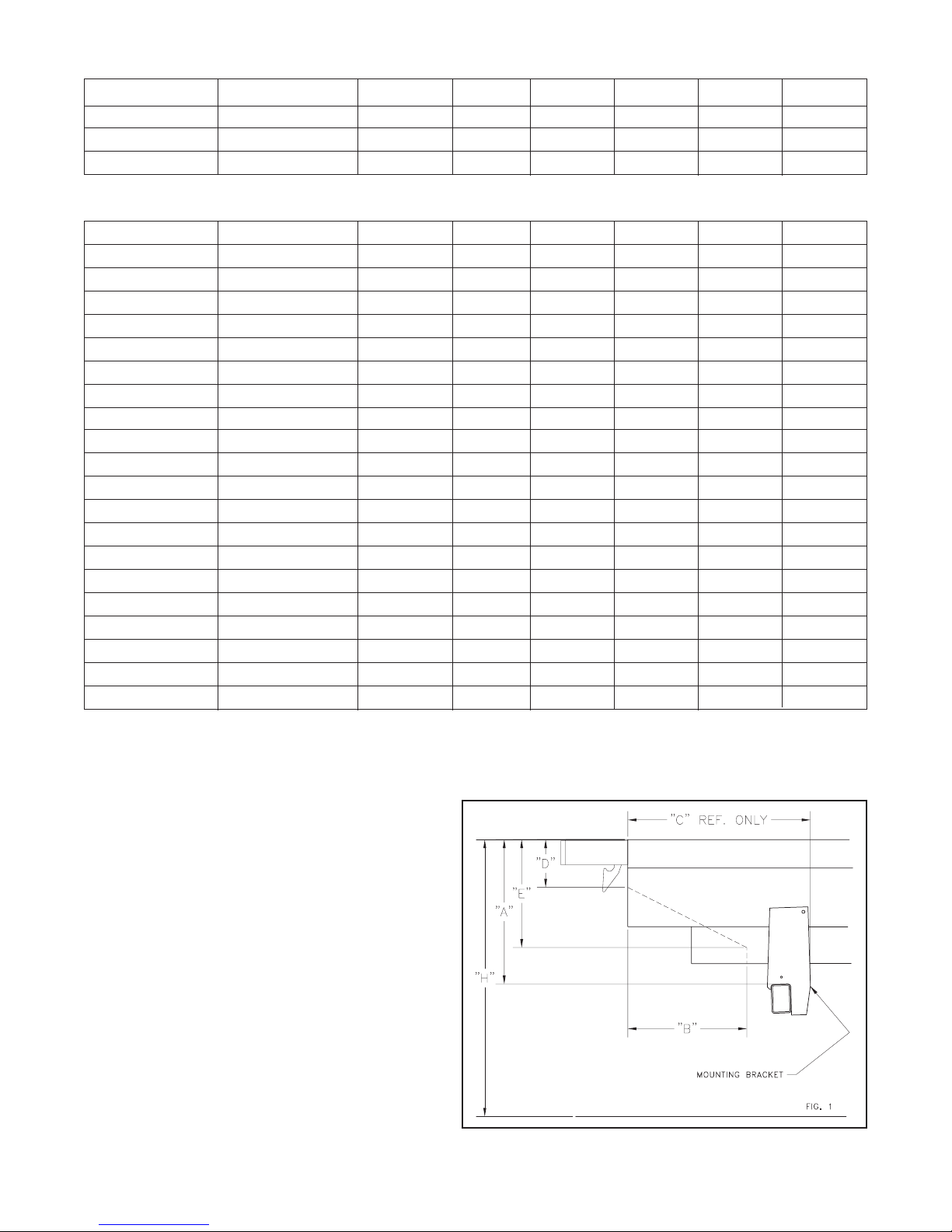
2. Reference figures 1 and 2 for charted dimensions on pages 2 thru 4.
3. All maximum mounting dimensions are shown with the vehicle empty; all minimum mounting dimensions are shown with the vehicle loaded.
4. Check bed height “H” when parked on a level surface.
5. Check “C” dimension for possible interference with spring hanger bracket before installation.
6. If the liftgate was ordered with the optional 216 receiver kit, use the loaded bed height (Hmin) to
determine what set of mounting dimensions to use. Bed height range for 216 Kit is 42" min. (vehicle
fully loaded) and 54" max. (vehicle empty).
ALL STEEL PLATFORMS (STEEL MAIN AND EXTENSION)
Platform Size Models H A B C D E
32+5 All Models 34"-40" 16.50 14.00 32.00 4.00 5.50
38W MLB 16/20 34"-40" 16.50 14.00 32.00 4.00 5.50
36+6 M 16/20 37"-44.99" 19.50 17.00 30.50 5.00 8.00
45"-50" 22.00 16.00 28.50 5.50 10.00
50"-54" 25.00 15.00 25.50 6.50 13.00
36+6 M 25/30 38"-44.99" 19.50 17.00 30.50 5.00 8.00
45"-50" 22.00 16.00 28.50 5.50 10.00
50"-54" 25.00 15.00 25.50 6.50 13.00
42+6 All Models 42"-45" 19.50 18.50 30.50 5.00 8.00
45"-50" 22.00 17.50 28.50 5.50 10.00
50"-54" 25.00 16.50 25.50 6.50 13.00
42+10 RET M 16/20 37"-45" 19.50 17.00 30.50 4.19 6.00
45"-50" 22.00 16.50 28.50 4.75 8.00
50"-54" 25.00 16.00 25.50 5.50 11.00
42+10 RET M/MDC 25/30 38"-45" 19.50 17.00 30.50 4.19 6.00
45"-50" 22.00 16.50 28.50 4.75 8.00
50"-54" 25.00 16.00 25.50 5.50 11.00
42W All Models 45"-50" 22.00 16.00 28.50 5.50 10.00
50"-54" 25.00 15.00 25.50 6.50 13.00
2.
STEEL MAIN SECTION/ALUMINUM EXTENSION PLATFORMS
Platform Size Models H A B C D E
48W M/MDC25 45"-49.99" 22.00 17.00 28.50 5.50 10.00
50"-54" 25.00 15.00 25.50 6.50 13.00
48W MDCLB 25 38"-45" 19.50 17.00 30.50 5.00 8.00
ALL ALUMINUM PLATFORMS (ALUMINUM MAIN AND EXTENSION)
Platform Size Models H A B C D E
27+6 MLB 16/20/25 34"-40" 16.50 13.00 32.00 4.50 5.50
37W MLB 16/20 34"-40" 16.50 13.00 32.00 4.50 5.50
36+6 M16/20 37"-44.99" 19.50 18.00 30.50 5.00 8.00
45"-50" 22.00 17.00 28.50 5.50 10.00
50"-54" 25.00 16.00 25.75 6.50 13.00
36+6 MDC/M25/30 38"-44.99" 19.50 19.00 30.50 5.00 8.00
45"-50" 22.00 18.00 28.50 5.50 10.00
50"-54" 25.00 16.50 25.75 6.50 13.00
40+6 All Models 42"-45" 19.50 19.00 30.50 5.00 8.00
45"-50" 22.00 18.00 28.75 5.50 10.00
50"-54" 25.00 16.50 26.00 6.50 13.00
42+10 RET M 16/20 37"-44.99" 19.50 19.00 30.50 4.50 6.50
45"-50" 22.00 18.00 28.50 5.00 8.50
50"-54" 25.00 16.50 25.75 6.00 11.50
42+10 RET M/MDC 25/30 38"-44.99" 19.50 19.00 30.50 4.50 6.50
45"-50" 22.00 18.00 28.50 5.00 8.50
50"-54" 25.00 16.50 25.75 6.00 11.50
48W M/MDC25 45"-49.99" 22.00 18.00 28.50 5.50 10.00
50"-54" 25.00 16.25 25.75 6.50 13.00
48W MDCLB25 39"-45" 19.50 19.00 30.50 5.00 8.00
A—Distance from top of bed to trunnion
tube.
B, D, E—Clearance needed for platform in
closed position.
C—Minimum distance needed for
mounting plates.
F, G, J, K—Rubrail notch dimension. See
figure 2.
H—Distance from ground to bed height.
3.

INSTALLATION INSTRUCTIONS
Step 1 Remove banding from gate undercarriage. Inspect for obvious shipping damage or
missing parts.
Step 2 If necessary notch rear of body as shown in figure 2.
Step 3 Center and level spacer at rear of body and tack weld into position. See figure 3.
4.
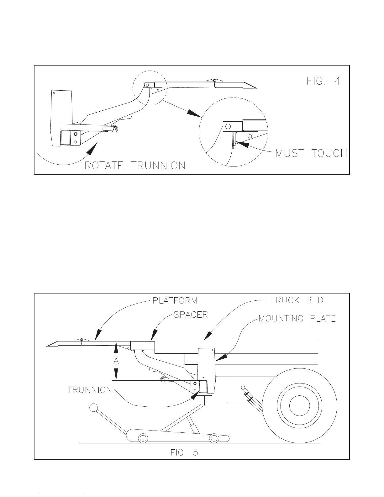
Step 4 Raise the liftgate by lifting under the main section of the folded platform with a forklift.
Make sure the platform is clamped securely to the forks. With the trunnion and liftarms
hanging from the platform, the platform rib and pivot assembly should make firm contact.
The installer may need to rotate the trunnion, as shown, to make this contact. Tack weld
the platform hinge to the pivot assembly to maintain contact. See figure 4.
Step 5 Using a forklift or crane, center and position liftgate behind vehicle and jack trunnion into
position. See figure 5 and 1 for “A” dimension. Note: Do Not connect hydraulic lines at
this time, the M series liftgates are pre-assembled with cylinder and pump mounted. On
certain installations, for instance a truck with a rear fuel tank, the pump may get in the
way of obtaining the proper “A” dimension. In most of these cases, Except for the 50" to
54" bed height range, where the “A” dimension is 25.00, the pump may be removed and
then mounted to the second, more rearward, set of holes in the pump mounting bracket
to provide more clearance. Note: Do Not move pump when the “A” dimension is 25.00
because the platform will not stow properly.
Step 6 Cut a small post or similar item to the correct length and place it under the platform so
the platform and payload area are at the same height. Place barrels or other protective
equipment under the platform so that the gate will not accidentally fall and injure someone.
5.
 Loading...