

Thiele SPS.2000.ADV RT, SPS.750.ADV RT, SPS.3000.ADV RT, SPS.1500.ADV RT(B0), SPS.2000.ADV RT(B0) User Manual
...
Vorderer Weinberg 26 • D-71522 Backnang • Tel.:+49 (0)7191 3560-0 (Fax.:-19)
UNINTERRUPTIB LE P OWER S UPPLY (UPS) + LIGH TIN G FLOW D IM MER STABIL IZERS (I LUES T) + S WITC H MO DE P OWER S UPPLY + STATIC INVERTERS + PHOTOVOLTAIC INVERTERS + VO LTAGE STABILIZERS AND POWER L INE C O ND ITI ON ERS
UNINTERRUPTIBLE POWER SUPPLY
Thiele KG • Vorderer Weinberg 26 • D-71522 Backnang • Tel.:(07191)3560-0 • Fax.:(07191)3560-19 • info@thiele-electronic.de • www.thiele-electronic.de
USER'S MANUAL
SPS.AD VANCE RT series
Thiele KG • Vorderer Weinberg 26 • D-71522 Backnang • Tel.:(07191)3560-0 • Fax.:(07191)3560-19 • info@thiele-electronic.de • www.thiele-electronic.de
Vorderer Weinberg 26 • D-71522 Backnang • Tel.:+49 (0)7191 3560-0 (Fax.:-19)
Thiele KG • Vorderer Weinberg 26 • D-71522 Backnang • Tel.:(07191)3560-0 • Fax.:(07191)3560-19 • info@thiele-electronic.de • www.thiele-electronic.de
Thiele KG • Vorderer Weinberg 26 • D-71522 Backnang • Tel.:(07191)3560-0 • Fax.:(07191)3560-19 • info@thiele-electronic.de • www.thiele-electronic.de
Vorderer Weinberg 26 • D-71522 Backnang • Tel.:+49 (0)7191 3560-0 (Fax.:-19)
General index
1. Introduction.
1.1. Acknowledgement letter.
1.2. Using this manual.
1.2.1. Conventions and used symbols.
1.2.2. For more information and/or help.
1.2.3. Safety instructions.
Thiele KG • Vorderer Weinberg 26 • D-71522 Backnang • Tel.:(07191)3560-0 • Fax.:(07191)3560-19 • info@thiele-electronic.de • www.thiele-electronic.de
1.2.3. 1 . General safety warnings.
1.2.3.2. To keep in mind.
1.2.3.3. Safe ty warning regarding batteries.
2. Quality and standard guarantee.
2.1. Declaration of the management.
2.2. Standard.
2.3. Environment.
3. Presentation.
3.1. Views.
3.1.1. Equipment views.
3.1.2. Legend corresponding to the equipment vie ws.
3.2. Definition of the product.
3.2.1. Nomenclature.
3.3. De scr ipt ion an d o perat in g pr in cip le.
3.3.1. Main features.
3.4. Options.
3.4.1. Isolation transformer.
3.4.2. External maintenance manual bypass.
3.4.3. Integration in IT networks by means of the SNMP adaptor.
3.4.4. AS400 card.
3.4.5. MODBUS protocol.
3.4.6. Extensible rail kit for rack cabinet assembling.
4. Installation.
4.1 . To be considered in the installation.
4.2. Receptio n of the equi pment.
4.2.1 . Unpacking, content checking and inspection.
4.2.2. Storage.
4.2.3. Unpacking.
4.2.4. Vertical assembling -tower type- or rack.
4.2.4.1. Removing or fitting the beauty cover.
4.2.4.2. Rotation of control panel with LCD panel.
4.2.4.3. Vertical assembling -tower type-.
4.2.4.4. Vertical assembling -tower type- , with extended back up time
4.2.4.5. 19" rack cabinet assembling.
4.2.4.6. 19" rack c abinet as sembl ing, with ex tende d back up ti me (batter y
4.3. Connection.
4.3. 1 . Connection of input.
4.3.2. Connection of the IEC outlets.
4.3.3. Connection of the external batteries ( extended back up time) .
4.3.4. Connection of main input earth terminal
4.3.5. EPO terminals in UPSs > 1kVA (Emergency Power Off).
4.3.6. Communication port.
4.3.6.1. RS232 and USB interface.
4.3.6.2. Smart slot.
4.3.6.3. AS400 Interface with DB9 output ( option ) .
4.3.6.4. Protec tion aga inst tran sient volt ages for mo dem / ADSL / Fax / ...
4.3.7. Software.
4.3.8. Considerations before commissioning with load connected.
(battery module).
module).
terminal
( ).
lines.
5. Operating.
5.1. Start up.
5. 1 .1. Controls before commissioning.
5.2. UPS start up and shutdown.
5.2.1 . Initial UPS start up.
5.2.2. UPS start up, with mains present.
5.2.3. Start up of the UPS, with no mains present.
5.2.4. UPS shutdown, with mains present.
5.2.5. UPS shutdown, with no mains present.
6. Control panel.
6.1. Functionalities.
6.1.1. Button functions.
6.1.2. Acoustic alarms.
6.1 .3. UPS status and colour of the LCD panel, depending on the condition.
6.1 .4. Graphics displayed in the LCD panel.
6.1.5. User settings.
6.1.6. Explanations about the user settings and other ones.
6.1.6.1. Operating modes.
6.1.6.2. IEC outlet groups.
6.1.6.3. Setting the UPS to connect it with "n" battery modules.
6.1.6.4. Setting the "Green" function.
7 . Maintenance, warranty and service.
7. 1 . Maintenance of the battery.
7.1.1. Notes for installing and replacing the batteries.
7.2. UPS T rouble Shooting guide.
7 .2. 1 . FAQ. Acoustic alarms.
7 .2.2. FAQ. General indications.
7.3. Warranty conditions.
7.3.1. Covered product.
7.3.2. Warranty terms.
7 .3.3. Out of scope of supply.
7.4. Description of the available maintenance and service
contracts.
7.5. Technical service network.
8. Annexes.
8.1. Main general specifications.
8.2. Glossary.
( ) and the earth bonding
Thiele KG • Vorderer Weinberg 26 • D-71522 Backnang • Tel.:(07191)3560-0 • Fax.:(07191)3560-19 • info@thiele-electronic.de • www.thiele-electronic.de
SALICRU
3
Vorderer Weinberg 26 • D-71522 Backnang • Tel.:+49 (0)7191 3560-0 (Fax.:-19)
1. Introduction.
1.1. Acknowledgement letter.
We would like to thank you in advance for the tr ust you have
placed in us by purchasing this product. Read this instruction
Thiele KG • Vorderer Weinberg 26 • D-71522 Backnang • Tel.:(07191)3560-0 • Fax.:(07191)3560-19 • info@thiele-electronic.de • www.thiele-electronic.de
manual carefully before starting up the equipment and keep it for
any possible future consult that can arise.
We remain at you entire disposal for any furt her informati on or
any query you should wish to make.
Yours sincerely.
SALICRU
1.2. Using this man ual.
T he equipment here descri bed can cause important
physical damages due to wrong handling. This is
why, the maintenance and/or fixing of the here described
equipment must be done by our staff or specifically au-
thorised.
According to our policy of constant evolution, we reserve
the right to modify the specifications in part or in
whole without forewarning.
All reproduction or third party concession of this
manual is prohibited without the previous written authorization of our firm.
instructions can cause serious incidents. Those indications with
“CAUTION ” symbol content features and basic instructions for
safety of the things. T o not respect such instructions can damage
the goods.
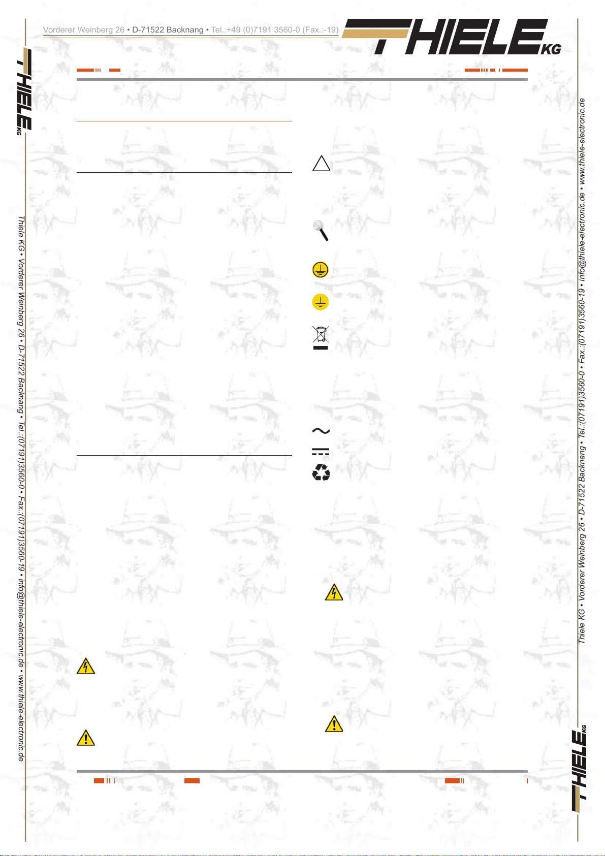
«Precaution» symbol. Read the paragraph text and take
the stated preventive mediums, it contents the basic instructions an d features for t he eq uip me nt safet y. To not respect
these indications can create material damages on the own equipment, installation or loads.
«Notes of information» symbol. Additional topics that
complement the basic procedures. These instructions are
important for the equipment use and its optimum efficiency.
«Main protective earthing terminal» symbol. Connect
the earth cable coming from the installation to this terminal.
«Earth bonding terminal». Connect the earth cable coming
from the load and the external battery cabinet to this te rminal.
Preservation of the environment: The presence of this
symbol in the product or in their associated documentation
states that, when its useful life is e xpired, it will no t be disposed together with the domestic residuals. In order to avoid
possible damages to the environment, separate this product
from other residuals and recycle it suitably. The users can contact with their provider or with the pertinent local authorities to be
informed on how and where they can take the product to be recycled and/or disposed correctly .
Alternating Current A.C..
Direct Current D.C..
The target of this manual or p u b l i catio n is to provid e i n f o rmati o n
reg ardi ng th e safe ty an d to give explanations abou t the procedures for the installation and ope rating of the e quipme nt. This
manual and re s t o f s up p o r t d o c um e nt at i o n has to be read carefully before installing, location change, setting or any handling of
any kind, including the start up and shutdown operation.
Keep this document for future consults.
In the next pages, the “equipmen t” and “S.T.S.” terms, are re -
ferred to the Uninterruptib le Power Supply or UPS and Ser v ice
and Technical Support respectively.
1.2.1. Conventions and used symbols.
Some or all the symbol s of t h i s s ection can be used and show n
in the equipment and/or in the description of this document. It is
advisable to be familiar with them and understand their meaning.
«Danger of electrical discharge» sym bol. Pay special
attention to it, both in the indication on the equipment and
in the paragraph referred to this user’s manual, because it contents features and basic infor mations for person safet y. To not
respect these indications can result in serious incidents or even
the death due to electrical discharges
«Warning» symbol. Carefully read the indicated paragraph and take the stated prevention measures, so it con-
tents basic safet y instruc tions for p ersons. To not respect suc h
Recycle.
1 .2.2. For m o r e i n forma t i o n a n d/or h e l p .
For more information and/or help of your specific unit, contact
with our Service and Technical Support (S.T.S.).
1.2.3. Safety instructions.
Ŗ Check the data of t he na mep late are t he re quir ed by t he in -
stallation.
Ŗ
Ŗ
Never forget that the UPS is a gen erator of elec trical energy , therefore the user has to take precau-
tions about against direct and indirect contacts.
Its energy source, a part from the AC mains, lies on the batteries, usually included in the same case or cabinet that the
equipment electronics. However, some models and/or extended back up times, batteries can be supplied in a separate
case or cabinet.
If the batteries are connected to the equipment and their protections are switched “On”, whenev er the y ar e, it is irrele van t
if the UPS is or not connected to mains, as well as the status
of the mains protect ion. The out lets or outp ut power bloc ks
will supply voltage meanwhile the battery set has energy.
Compliance as regards to “Safety instructions“ is
mandatory, being the user the legal responsible
regarding to its observance and application. Read them care-
fully and follow the stated steps in the established order , keep
them for future consults that ma y arise .
Thiele KG • Vorderer Weinberg 26 • D-71522 Backnang • Tel.:(07191)3560-0 • Fax.:(07191)3560-19 • info@thiele-electronic.de • www.thiele-electronic.de
4
USER MANUAL

Vorderer Weinberg 26 • D-71522 Backnang • Tel.:+49 (0)7191 3560-0 (Fax.:-19)
Ŗ If the instructions are not in total or partial and in
Ŗ
Thiele KG • Vorderer Weinberg 26 • D-71522 Backnang • Tel.:(07191)3560-0 • Fax.:(07191)3560-19 • info@thiele-electronic.de • www.thiele-electronic.de
Ŗ
Ŗ A person is defined as qualified, if it has experience of as-
Ŗ Place the equipment the closest to the power supply and
Ŗ Warning labels should be placed on all primary power
1.2.3.1. General safety warnings.
Ŗ All connections and disconnections of the cables from the
Ŗ Shutdown the equipment completely by switching «Off» the
Ŗ
Ŗ Cross cable sections used to supply the equipment and loa ds,
Ŗ
special referred to the safety, do not carry on with
the installation or commissioning tasks, because there
could be a risk on your safety or on the other/s persons,
being able to make serious injuries even the death, also it
can cause damages to the equipment and/or to the loads
and installation.
The local ele ctrical regulations and t he different re-
strictions of the client's site, they can invalidate some
recommendations included in the manuals. When discrepancies exist, the user has to comply the local regulations.
The equipments provided with power cord with plug
and outle ts, can be conne cted and u sed b y pe rsonne l
without any kind of experience.
sembling, commissioning and perfect control operating of
the equipment, if he has the requirements to do the job and
if has read and underst and all the things desc ribed in this
manual, in particular the safety indications. Such preparation
is considered only valid if it is certified by our S.T.S..
loads to be supplied, leaving an easy access if it were needed
an urgent disconnection.
switches installed in places away from the equipment to alert
the electri cal maintenance pers onnel of the presence of a
UPS in the circuit
The label will bear the following text or an equivalent one:
Before working in this circuit.
Ŗ Isolate the Uninterruptible Power System (UPS).
Ŗ Check the voltage between all terminals including the
protective earth.
Risk of voltage feedback from UPS.
equipment, including the control ones, will be done with no
power supply and the swit ches on rest, position «O» or «Off» .
button of the control panel first. Next disconnect the cable or
by switching «Off» the input circuit breaker of the installation.
The indiscriminate manoeuvring of the switches may
involve production losses and/or equipment damages. Consult the documentation before doing any action
Pay special attention to the labelling of the equipment
that warns about the «Electrical shock h azard» . Inside
the equipment there are dangerous voltages, never open the
enclosure, the access has to be done by qualified staff. In
case of maintenance or fault, consult to the closest (S.T.S.).
will be according to the nominal current stated in the namepla te
label of the equipment, and respecting the Low Voltage Electrotechnical Regulations or standards of the country.
Use approved cables only
Protection Ear th ca ble of the UPS dr ives the leak age
current of the load devices. An isolated earth cable has
to be installed as part of the circuit that supplies the equipment. Cross cab le sectio n and its features will b e same as
the power supply cables, but with green colour with or without
the yellow strip .
All outlets of the UPS has an earth bonding, duly connected
and those equipments with powe r blocks there is a n exclusiv e
terminal for the load earth connection. When an outgoing distribution is done, i.e pow er strips, it is essential tha t the y ha v e
an earth terminal connected to each one of them.
It is essential that the cables th at supplies the loa ds have the
earth connection cab le .
The protection earth must be connec ted to t he fr am e
or metallic chassis of any el ectrical equipment (in our
case to the UPS, battery cabinet or case and loads) , assuring
that it is done before connecting the input voltage.
Check the quality and availability of the earth, it has to be
between the defined parameters by the local or national
regulations.
Ŗ For the smallest devices (the ones connected with the fore-
seen power cord wit h plug), the user has to check th e wall
outlet corresponds with the type of supplied plug, with earth
duly installed and connected to the local protection earth.
Ŗ
During the normal UPS operation, the power cord
cable can't be discon nect ed f rom w al l ou tlet , beca use
the protection earth of the own UPS would be dis c o n n e cted
and also the earth from the loads connected to the output.
For this reason, the g eneral protection eart h cable of the
building or switchgear panel that supplies the UPS will not
be disconnected.
Ŗ Check that the sum of the leakage currents of the UPS and
connected load/s do not exceed over 3,5mA.
Ŗ The installation will have input protections sized to the cur-
rents of the equip ment and stated in the nameplate label
(RCD devices type B and c ircui t breakers wit h C charac teristic or any other equivalent one) .
Overload conditions are considered as a nonpermanent an
exceptional operat ing mode, so these currents will n ot be
kept in mind when sizing the prot ections.
Ŗ Do not overload the UPS by co nnecting loads wit h inrush
consumptions at its output, like laser printers.
Ŗ Output protection will be done with a circuit breaker of C char-
acteristic or an equivalent one.
It is recommended to distribute the output power, into four
lines as minimum. Each one of them will have a protection
circuit breaker sized to the quarter of the nominal power.
This kind of outgoing distributions will allow that any fault in
any device con n ect ed to the equipment, tha t makes a shortcircuit, will affect to the line with the faulty device only. An
uninterruptible power supply will be guaranteed t o the rest of
connected loads, due to the protection tripping of the affected
line by the short-circuit only.
Ŗ When replac i ng a fuse, do i t for a nother of the same typ e, char-
acteristics format and size.
Ŗ Under any concept the input power cord will be connected to the
output of the equipment, either directly or through other ways.
Ŗ All the equipm ents have an auxiliar y terminal stri p to install
an external emergency power off button (EPO ), and it will belong to the user property.
Type of circuit is selectable through the LCD panel of the equipment. The contact is preset from factory as normally open, so
the button must be switched to close the circuit and the voltage
to the loads is broken. To establish the power supply to the
loads again, the EPO button must be deactivated.
EPO doesn't affect to the power supply of the equipment, it
only breaks the power supply t o the loads as a safety measure.
Ŗ
When supplying input voltage to a UPS with fitted in or
separate static bypass, although the inverter is still
turned «Off» (deactivated) it doesn't mean that at the output
there will not be voltage.
Thiele KG • Vorderer Weinberg 26 • D-71522 Backnang • Tel.:(07191)3560-0 • Fax.:(07191)3560-19 • info@thiele-electronic.de • www.thiele-electronic.de
SALICRU
5

Vorderer Weinberg 26 • D-71522 Backnang • Tel.:+49 (0)7191 3560-0 (Fax.:-19)
Ŗ
Thiele KG • Vorderer Weinberg 26 • D-71522 Backnang • Tel.:(07191)3560-0 • Fax.:(07191)3560-19 • info@thiele-electronic.de • www.thiele-electronic.de
Ŗ All power supply electrical cables have to be fixed to the
Ŗ CHASSI S or RA CK m ou nt ed eq ui pme nt s a re de st in ed to be i n-
Ŗ Never manipulate the equipment with we t hands.
1.2.3.2. To keep in mind.
Ŗ Do not try to dismantle or change any part of the
Ŗ If it is observed that the UPS exhausts smoke or toxic gas,
Ŗ In case of an accidental equipment dropping or if the enclo-
Ŗ Do not cut, manipulate the electrical cables, do not put heavy
Ŗ When moving an equipment from a cold place to a warm en-
So, to do it, the input and static bypass switches will have to
be turned «Off».
Put warnings of danger and/or eme rgency switches if the safe ty
Standards require it in your particular installation.
It is possible that the UPS supplies output voltage
through the manual bypass to those equipments that
incorporate it either standard or optional, so it will have to be
considered as regards to safety. If it w ere necessary to break
the output supply of the equipment in this situation, deactivate
the outgoing distribution protection or in case of lack of it the
general protection of the distribution panel that feeds the UPS.
equipments and loads, interfaces, etc..., to unmovable parts
and in the way to avoid treads, trips on t hem or fortuitous
pulls.
stalled in a predetermined set to be done by professionals.
The installation has to be designed and executed by qual-
ified personnel, who will be the responsible to apply the
safety and EMC regulati on s and st and ards t hat c ontr ols
the particular installations where the product is destined.
The equipments assembled in CHASSIS do not have
enclosure protec tion, even the p ower blocks are u nprotected.
Some RACK mounted equipments do not have the pow er
blocks protected.
equipment, if this action is not contemplated in this
document. Manipulation inside the UPS due to an y modification, reparation or any other cause, can make an electrical
discharge of high voltage and it is restricted to qualified staff
only. Do not open the equipment.
A part from the implicit stated risks, any action that make the
modification, internal or external of the equipment or just only
the simple intervention inside of itself, which is not stated in
this document, it can expire the warranty.
shutdown it immediately and disconnect it from the power
supply. This kind of fault can cause fire or electrical discharge. Contact with ou r (S.T.S.).
sure is damaged, do not start it up under any concept. This
kind of fault can cause fire or electrical discharge. Contact
with our (S.T.S.).
objects over them to o. Any of these actions c ould cause a
short-circuit and make a fire or electrical discharge.
Check that the elect rical cabl es of connection , plugs and ou tlets are in good conditions.
vironment and vice versa, it can cause condensation (small
water drops) in the external and internal surfaces. Before installing a moved equipment from another place or even packaged, the equipment will be left for a minimum time of two
hours in the new location before making any action, with the
purpose of adapti ng it to the new environ mental con ditions
and avoid the possible condensations.
The UPS has to be completely dry before starting any installation task.
Ŗ Do not store, install or expose the equipment in corrosive,
wets, dusty inflammable or explosive environments and
never outdoors.
Ŗ Avoid to locate, install or store the equipment in a place with
direct sunlight or high temperatures. Batteries could be damaged.
In the exceptional ca se and lo ng expo sit ion to inte nse he at,
batteries can cause filtrations, overheating or explosions,
which can cause fires, burn or other injuries. High temperatures can also make deformation in the plastic enclosure.
Ŗ The location will be spacious, airy, away from heat sources
and easy access.
Ŗ Do not obstruct the cooling grids by entering objects through
themselves or other orifices.
Ŗ Leave as minimum s p ace of 25 cm in the equipment pe-
ripheral.
Ŗ Do not put materials over the equipment or parts that obstruct
the correct visualization of the synoptic.
Ŗ Be careful to not wet it, because it is not waterproof. Do not
allow entering any kind of liquids in. If accidentally the outside
of the machine comes into contact with liquids or salt air, dry
it with a soft and absorbent cloth.
Ŗ To clean the equipment, wipe over a damp cloth and then
dry it. Avoid sprinkling or spillage that could enter through the
slots or cooling grids, which may cause fire or electric shock.
Do not clean the equipments with products that could have
alcohol, benzene, solvent or other inflammable substances,
or they are abrasive, corrosive, liquids or detergent.
Ŗ Be careful to not lift heavy loads without help, according to
the following recommendations:
d, < 18 kg.
dd, 18 - 32 kg.
ddd, 32 - 55 kg.
, > 55 kg.
Ŗ UPSs are electronic equipments, so they will be treated as
they are:
Avoid shocks.
Avoid jolting or bouncing of the UPS, l ike those produced
by moving the equip ment o n a hand t ruc k and m ove on
an uneven or wavy surface.
Ŗ UPS transport will be done packaged inside its original pack -
aging in order to prevent it from shock and impact and by
means of the suitable type of packaging (carton box, pallet
packaging, ... ) and appropriate t o its we ight.
Ŗ Although the physical location of the elements can differ from
the illustrations in this manual in some cases, the correct labelling correct the possible doubts and makes easy its com-
prehension.
1.2.3.3. Safety warning regarding batteries.
Ŗ The manipulation and connection of the batteries
shall be done and supervised by personnel with
battery knowledge only.
Before doing any action, disconnect the batteries. Check that
no current is present and there is not dangerous voltage in
the DC BUS (capacitors ) or in the endpoint of the ba ttery set
terminals.
Battery circuit is not isolated from input voltage. Dangerous
voltages can be found between the terminals of the batter y
set and the eart h. Che ck t hat t here i s not any vol tag e at t he
input before take any action over them.
Thiele KG • Vorderer Weinberg 26 • D-71522 Backnang • Tel.:(07191)3560-0 • Fax.:(07191)3560-19 • info@thiele-electronic.de • www.thiele-electronic.de
6
USER MANUAL
Vorderer Weinberg 26 • D-71522 Backnang • Tel.:+49 (0)7191 3560-0 (Fax.:-19)
Ŗ When faulty batteries are replaced, the complete battery set
Ŗ Generally, the used batteries are sealed lead acid of 12V and
Ŗ Do not reuse the faulty batteries. There could be an explo-
Thiele KG • Vorderer Weinberg 26 • D-71522 Backnang • Tel.:(07191)3560-0 • Fax.:(07191)3560-19 • info@thiele-electronic.de • www.thiele-electronic.de
Ŗ Generally supplied batteries are installed in the same cab-
Ŗ In those equipments requested without batteries, their ac-
Ŗ
Ŗ In order to avoid a complete di scharge of the bat teries and
Ŗ When the equipment and/or battery module has a protec-
Ŗ For long periods of disconnection, consider that the equip-
Ŗ Never short the bat tery termin als as it involves a high ris k. It
Ŗ Avoid mechanical efforts and impacts.
Ŗ Do not open or mutilate the battery. Spilled electrolyte is
has to be replaced, less exceptional cases in new equipments, were due to manufacturing faults it will only be replaced the defective ones.
The replacement will be done by another one of the same
type, v ol ta ge , cap ac ity, quanti ty a nd br an d. Al l of th em ha s t o
be of the same brand.
maintenance free (VRLA).
sion or burst any battery with the involved problems and issues that could happen.
inet, case or rack of the equipment. Depending on the power ,
autonomy or both, they can be supplied separately from the
equipment in another cabinet, case or rack, with the interlink
cables among them. Do not modify its length.
quisition, installation and connection of themselves will be
done by the end-user and under his responsi bility. Data
concerning the batteries as regards to quantity, capacity and
voltage, are stated in this battery label sticked beside the
nameplate of the equipment. Respect these data, bat tery
connection polarity and the supplied circuit diagram strictly.
For an optimum and efficient operating, the battery set has to
be located as close as possible to the equipment.
The battery voltage can involve the risk of electric
shock and can prod uce high short circuit currents.
Observe the following preventive measures before manipulating any terminal block identified in the labelling as «Batteries» :
Disconnect the corresponding protection elements.
When connecting a battery cabinet to the equipment,
respect the cable’s polarity and colour (red-positive;
black-negative) indicated in the manual and in the corresponding labelling.
Wear rubber gloves and shoes.
Use tools with insulated handles.
Take off watches, rings or other metal objects.
Do not place metal tools or objects over the batteries.
Never manipulate with your hands or through conducting
objects, do not short either the batter y terminal block of
the equipment or the own from the batteries.
as a safety measure after a long blackout of the commercial
mains and when ending the working day, proceed to the load
shutdown and then to the equipment too, by following the operating described in this «User's manual».
tion through a fuse and it were needed to be replaced, it will
always be done by another one wi th the same dimensi on,
type a n d s i ze.
ment has to be connected once a month for 10 hours as
minimum, in order to charge the batteries, so the irre v e rsible
degradation of itself is avoided. On the other hand, in case of
storing an equipment, it will be done in a fresh and dry place,
never outdoors.
involves the detriment of the equipment and batteries.
harmful and toxic to the skin and eyes.
Ŗ Do not dispose the batteries in a fire and high temperatures.
The batteries may explode .
Ŗ In case of contac t of the acid with part s of the body, wash
immediately with plenty water and call urgently the nearest
medical service.
Ŗ Batteries involve a ser i o us risk for the health and for the en -
vironment. Their disposal should be done according to the
existing laws.
Thiele KG • Vorderer Weinberg 26 • D-71522 Backnang • Tel.:(07191)3560-0 • Fax.:(07191)3560-19 • info@thiele-electronic.de • www.thiele-electronic.de
SALICRU
7
Vorderer Weinberg 26 • D-71522 Backnang • Tel.:+49 (0)7191 3560-0 (Fax.:-19)
2. Quality and standard
2.1. Declaration of the management.
Thiele KG • Vorderer Weinberg 26 • D-71522 Backnang • Tel.:(07191)3560-0 • Fax.:(07191)3560-19 • info@thiele-electronic.de • www.thiele-electronic.de
Our target is the clien t’s satisfaction, therefore this Man a gemen t
has decided to e st a b li sh a Q u ali ty and Environmental policy, by
means of installation a Quality and Environmental Management
System that becomes us capable to comply the requirements
demanded by the standard IS O 9001 and ISO 14001 and by our
Clients and concerned parts too.
Likewise, the enterprise Management is committed with the development and improvement of the Qualit y and Environmental
Management System, th rough :
Ŗ The communication to all the company about the impor-
Ŗ The Quality and Environmental Policy diffusion and the fixa-
Ŗ To carry out revisions by the Management.
Ŗ To provide the needed resources.
2.2. Standard.
guarantee.
tance of satisfaction both in the client’s requirements and in
the legal and regulations.
tion of the Quality and Environment targets.
2.3. Environment.
This product has been designed to respect the environment
and has been manufactured in accordance with the standard
ISO 1 4001.
Equipment recycling at the end of its useful lif e :
Our company commi ts to use t he ser vi ces of aut horis ed so cie -
ties and according to the regulations, in order to treat the recovered product at the end of its useful life (contact your distributor).
Packaging:
To recycle the packing, follow the legal regula tions in force .
Batteries:
The batteries mean a seri ous danger for health and environ -
ment. The disposal of them must be done in accordance with
the standards in force .
The SPS.ADV ANCE RT product is designed, manuf actured and
commercialized in acc ordan ce with th e standard EN ISO 9001
of Quality Management Systems. The
conformity to t he EEC Directive by means of th e applicat ion of
the following standards:
Ŗ 2006/95/EC Low voltage directive.
Ŗ 2004/108/EC Electromagnetic Compatibility directive
(EMC).
In accordance with the specifications of the harmonized standards. Standards as r ef ere nce :
Ŗ EN-IEC 62040 -1. Uninterrupti ble power supply (UPS). Part
1-1: General and safety requirements for UPS’s used in accessible areas by end users..
Ŗ EN-IEC 60950-1. IT equipments. Safety. Part 1: General re-
quirements.
Ŗ EN-IEC 62040 -2. Uninterruptible p ower supply (UPS). Part
2: EMC requirements.
The manufacturers responsibility is ex cluded in the event
of any modification or intervention in the product by the
customer’s side.
This is a product for i ts use in co mmerci al and indu strial
applications, so restrictions and additional measures can
be needed in the installation to prev ent perturbations.
marking shows the
Thiele KG • Vorderer Weinberg 26 • D-71522 Backnang • Tel.:(07191)3560-0 • Fax.:(07191)3560-19 • info@thiele-electronic.de • www.thiele-electronic.de
Declaration of conformity CE of the product is at the client
i
disposal under previous request to our headquarters offices.
8
USER MANUAL
Vorderer Weinberg 26 • D-71522 Backnang • Tel.:+49 (0)7191 3560-0 (Fax.:-19)
3. Presentation.
3.1. Views.
3.1.1. Equipment views.
Thiele KG • Vorderer Weinberg 26 • D-71522 Backnang • Tel.:(07191)3560-0 • Fax.:(07191)3560-19 • info@thiele-electronic.de • www.thiele-electronic.de
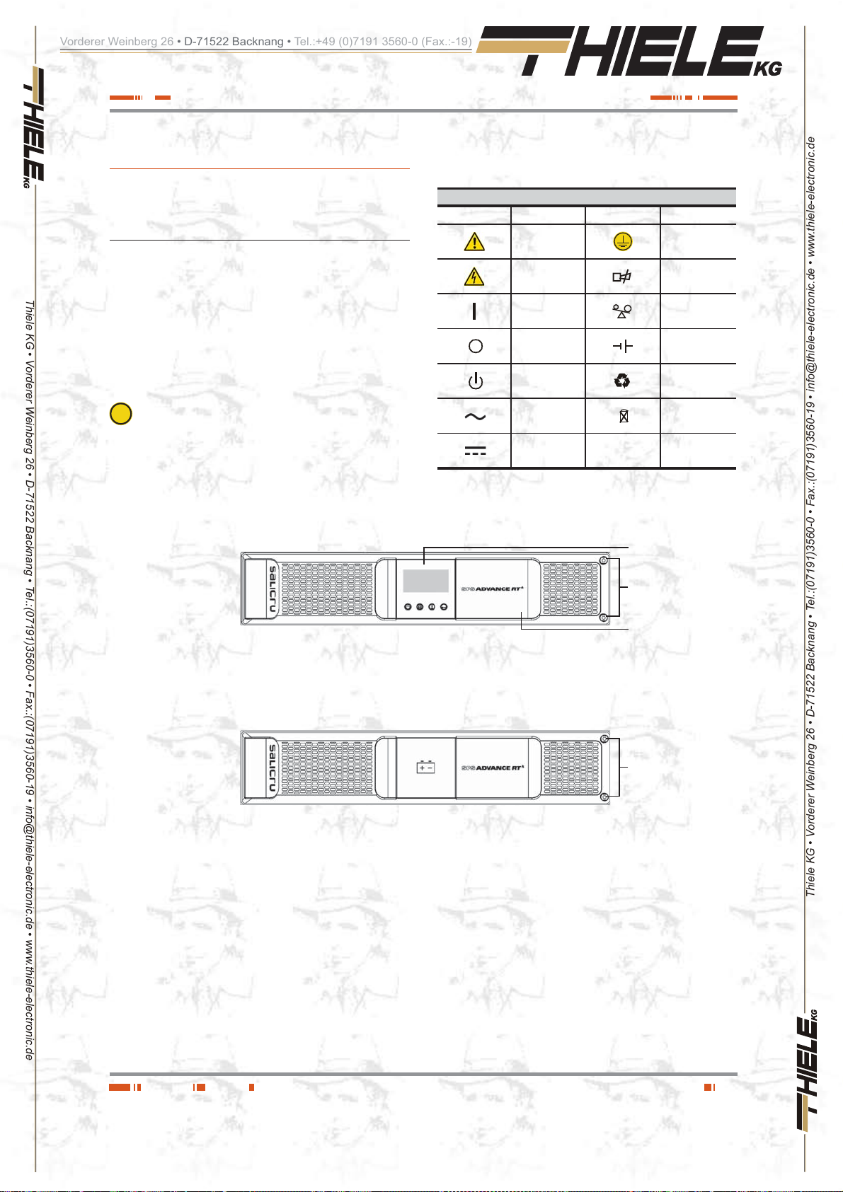
Figures 1 to 3 shows the illustrations of the equipment according
to the format of the enc losure and related to the power of t he
model. Neverth eless and due to the const ant evolution of the
product, sev e ral discr epa ncies or sma ll co ntr adict ions can aris e.
If you have any doubt, the labelling on the equipment will alwa ys
prevail.
checked. Act in accordance with the installation.
In the nameplate sticked in the equipment, all the data re-
i
ferred to the main features of the equipment can be
3. 1 .2. Legend corresponding to the
equipment view s.
Symbol and their meaning
Symbol Meaning Symbol Meaning
Warning Earth
Electrical shock Alarm silenced
UPS ON /
Battery test
UPS OFF Battery
UPS on Standby
or shutdown
Alternating (AC)
Direct (DC)
Tab la 1. Used symbology in the equipment and/ or this manua l. .
Control panel
with LCD
Fixing screws,
Plastic beauty
front
Overload
Recycling
Keep the UPS i
a well ventilated
place
Front virew ADVANCE RT
Front view battery module for ADV ANCE RT
Fig. 1. Front view models from 0,7 to 10 kVA and battery
modules for extended back up times.
Plastic beauty
front
Fixing screws,
Plastic beauty
front
Thiele KG • Vorderer Weinberg 26 • D-71522 Backnang • Tel.:(07191)3560-0 • Fax.:(07191)3560-19 • info@thiele-electronic.de • www.thiele-electronic.de
SALICRU
9
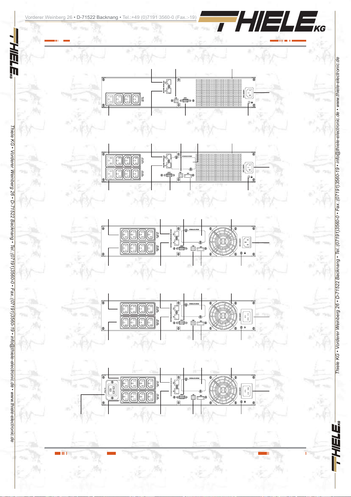
Vorderer Weinberg 26 • D-71522 Backnang • Tel.:+49 (0)7191 3560-0 (Fax.:-19)
Thiele KG • Vorderer Weinberg 26 • D-71522 Backnang • Tel.:(07191)3560-0 • Fax.:(07191)3560-19 • info@thiele-electronic.de • www.thiele-electronic.de
Standard 750 a nd
1000 VA models
Standard 1500 VA and
(B1)models
IEC outlets
IEC outlets
"LS1"
IEC outlets
"LS2"
IEC outlets
"LS1"
Output connector, with Módem
/ ADSL / Fax / ... protection Fan
Input connector, for modem
/ ADSL / Fax / ... line
Output connector, with Módem
/ ADSL / Fax / ... protection
Input connector, for modem
/ ADSL / Fax / ... line
Output connector, with Módem
/ ADSL / Fax / ... protection
USB COM
port
RS232 COM
USB COM
port
RS232 COM
port
RS232 COM
port
port
protection cover
Connector for
external EPO
protection cover
Smart slot
Smart slot
Earth connection
for battery module
Fan
Earth connection
for battery module
Fan
IEC inlet for AC
power supply
IEC inlet for AC
power supply
Standard 2000 VA
model
IEC outlets
IEC outlets
2000 V A ( B 1) model
IEC outlets
IEC outlets
Standard 3000 VA and
(B1)model
"LS2"
"LS1"
"LS2"
"LS1"
Input connector, for modem /
ADSL / Fax / ... line
Output connector, with Módem
/ ADSL / Fax / ... protection
Input connector, for modem /
ADSL / Fax / ... line
Output connector, with Módem
/ ADSL / Fax / ... protection
USB COM
port
RS232 COM
port
USB COM
port
RS232 COM
port
Connector for
external EPO
Smart slot
protection cover
Connector for
external EPO
Smart slot
protection cover
Earth connection
for battery module
Fan
Earth connection
for battery module
Fan
IEC inlet for AC
power supply
IEC inlet for AC
power supply
IEC inlet for AC
power supply
Thiele KG • Vorderer Weinberg 26 • D-71522 Backnang • Tel.:(07191)3560-0 • Fax.:(07191)3560-19 • info@thiele-electronic.de • www.thiele-electronic.de
16A IEC outlets
Fig. 2. Rear view according to the model and power rate of
the equipments.
IEC outlets
"LS2"
Input connector, for modem /
ADSL / Fax / ... line
10
USB COM
port
Connector for
external EPO
Earth connection
for battery module
USER MANUAL
 Loading...