

Thiele SPS.2000.ADV RT, SPS.750.ADV RT, SPS.3000.ADV RT, SPS.1500.ADV RT(B0), SPS.2000.ADV RT(B0) User Manual
...Page 1

Vorderer Weinberg 26 • D-71522 Backnang • Tel.:+49 (0)7191 3560-0 (Fax.:-19)
UNINTERRUPTIB LE P OWER S UPPLY (UPS) + LIGH TIN G FLOW D IM MER STABIL IZERS (I LUES T) + S WITC H MO DE P OWER S UPPLY + STATIC INVERTERS + PHOTOVOLTAIC INVERTERS + VO LTAGE STABILIZERS AND POWER L INE C O ND ITI ON ERS
UNINTERRUPTIBLE POWER SUPPLY
Thiele KG • Vorderer Weinberg 26 • D-71522 Backnang • Tel.:(07191)3560-0 • Fax.:(07191)3560-19 • [email protected] • www.thiele-electronic.de
USER'S MANUAL
SPS.AD VANCE RT series
Thiele KG • Vorderer Weinberg 26 • D-71522 Backnang • Tel.:(07191)3560-0 • Fax.:(07191)3560-19 • [email protected] • www.thiele-electronic.de
Page 2
Vorderer Weinberg 26 • D-71522 Backnang • Tel.:+49 (0)7191 3560-0 (Fax.:-19)
Thiele KG • Vorderer Weinberg 26 • D-71522 Backnang • Tel.:(07191)3560-0 • Fax.:(07191)3560-19 • [email protected] • www.thiele-electronic.de
Thiele KG • Vorderer Weinberg 26 • D-71522 Backnang • Tel.:(07191)3560-0 • Fax.:(07191)3560-19 • [email protected] • www.thiele-electronic.de
Page 3
Vorderer Weinberg 26 • D-71522 Backnang • Tel.:+49 (0)7191 3560-0 (Fax.:-19)
General index
1. Introduction.
1.1. Acknowledgement letter.
1.2. Using this manual.
1.2.1. Conventions and used symbols.
1.2.2. For more information and/or help.
1.2.3. Safety instructions.
Thiele KG • Vorderer Weinberg 26 • D-71522 Backnang • Tel.:(07191)3560-0 • Fax.:(07191)3560-19 • [email protected] • www.thiele-electronic.de
1.2.3. 1 . General safety warnings.
1.2.3.2. To keep in mind.
1.2.3.3. Safe ty warning regarding batteries.
2. Quality and standard guarantee.
2.1. Declaration of the management.
2.2. Standard.
2.3. Environment.
3. Presentation.
3.1. Views.
3.1.1. Equipment views.
3.1.2. Legend corresponding to the equipment vie ws.
3.2. Definition of the product.
3.2.1. Nomenclature.
3.3. De scr ipt ion an d o perat in g pr in cip le.
3.3.1. Main features.
3.4. Options.
3.4.1. Isolation transformer.
3.4.2. External maintenance manual bypass.
3.4.3. Integration in IT networks by means of the SNMP adaptor.
3.4.4. AS400 card.
3.4.5. MODBUS protocol.
3.4.6. Extensible rail kit for rack cabinet assembling.
4. Installation.
4.1 . To be considered in the installation.
4.2. Receptio n of the equi pment.
4.2.1 . Unpacking, content checking and inspection.
4.2.2. Storage.
4.2.3. Unpacking.
4.2.4. Vertical assembling -tower type- or rack.
4.2.4.1. Removing or fitting the beauty cover.
4.2.4.2. Rotation of control panel with LCD panel.
4.2.4.3. Vertical assembling -tower type-.
4.2.4.4. Vertical assembling -tower type- , with extended back up time
4.2.4.5. 19" rack cabinet assembling.
4.2.4.6. 19" rack c abinet as sembl ing, with ex tende d back up ti me (batter y
4.3. Connection.
4.3. 1 . Connection of input.
4.3.2. Connection of the IEC outlets.
4.3.3. Connection of the external batteries ( extended back up time) .
4.3.4. Connection of main input earth terminal
4.3.5. EPO terminals in UPSs > 1kVA (Emergency Power Off).
4.3.6. Communication port.
4.3.6.1. RS232 and USB interface.
4.3.6.2. Smart slot.
4.3.6.3. AS400 Interface with DB9 output ( option ) .
4.3.6.4. Protec tion aga inst tran sient volt ages for mo dem / ADSL / Fax / ...
4.3.7. Software.
4.3.8. Considerations before commissioning with load connected.
(battery module).
module).
terminal
( ).
lines.
5. Operating.
5.1. Start up.
5. 1 .1. Controls before commissioning.
5.2. UPS start up and shutdown.
5.2.1 . Initial UPS start up.
5.2.2. UPS start up, with mains present.
5.2.3. Start up of the UPS, with no mains present.
5.2.4. UPS shutdown, with mains present.
5.2.5. UPS shutdown, with no mains present.
6. Control panel.
6.1. Functionalities.
6.1.1. Button functions.
6.1.2. Acoustic alarms.
6.1 .3. UPS status and colour of the LCD panel, depending on the condition.
6.1 .4. Graphics displayed in the LCD panel.
6.1.5. User settings.
6.1.6. Explanations about the user settings and other ones.
6.1.6.1. Operating modes.
6.1.6.2. IEC outlet groups.
6.1.6.3. Setting the UPS to connect it with "n" battery modules.
6.1.6.4. Setting the "Green" function.
7 . Maintenance, warranty and service.
7. 1 . Maintenance of the battery.
7.1.1. Notes for installing and replacing the batteries.
7.2. UPS T rouble Shooting guide.
7 .2. 1 . FAQ. Acoustic alarms.
7 .2.2. FAQ. General indications.
7.3. Warranty conditions.
7.3.1. Covered product.
7.3.2. Warranty terms.
7 .3.3. Out of scope of supply.
7.4. Description of the available maintenance and service
contracts.
7.5. Technical service network.
8. Annexes.
8.1. Main general specifications.
8.2. Glossary.
( ) and the earth bonding
Thiele KG • Vorderer Weinberg 26 • D-71522 Backnang • Tel.:(07191)3560-0 • Fax.:(07191)3560-19 • [email protected] • www.thiele-electronic.de
SALICRU
3
Page 4
Vorderer Weinberg 26 • D-71522 Backnang • Tel.:+49 (0)7191 3560-0 (Fax.:-19)
1. Introduction.
1.1. Acknowledgement letter.
We would like to thank you in advance for the tr ust you have
placed in us by purchasing this product. Read this instruction
Thiele KG • Vorderer Weinberg 26 • D-71522 Backnang • Tel.:(07191)3560-0 • Fax.:(07191)3560-19 • [email protected] • www.thiele-electronic.de
manual carefully before starting up the equipment and keep it for
any possible future consult that can arise.
We remain at you entire disposal for any furt her informati on or
any query you should wish to make.
Yours sincerely.
SALICRU
1.2. Using this man ual.
T he equipment here descri bed can cause important
physical damages due to wrong handling. This is
why, the maintenance and/or fixing of the here described
equipment must be done by our staff or specifically au-
thorised.
According to our policy of constant evolution, we reserve
the right to modify the specifications in part or in
whole without forewarning.
All reproduction or third party concession of this
manual is prohibited without the previous written authorization of our firm.
instructions can cause serious incidents. Those indications with
“CAUTION ” symbol content features and basic instructions for
safety of the things. T o not respect such instructions can damage
the goods.
«Precaution» symbol. Read the paragraph text and take
the stated preventive mediums, it contents the basic instructions an d features for t he eq uip me nt safet y. To not respect
these indications can create material damages on the own equipment, installation or loads.
«Notes of information» symbol. Additional topics that
complement the basic procedures. These instructions are
important for the equipment use and its optimum efficiency.
«Main protective earthing terminal» symbol. Connect
the earth cable coming from the installation to this terminal.
«Earth bonding terminal». Connect the earth cable coming
from the load and the external battery cabinet to this te rminal.
Preservation of the environment: The presence of this
symbol in the product or in their associated documentation
states that, when its useful life is e xpired, it will no t be disposed together with the domestic residuals. In order to avoid
possible damages to the environment, separate this product
from other residuals and recycle it suitably. The users can contact with their provider or with the pertinent local authorities to be
informed on how and where they can take the product to be recycled and/or disposed correctly .
Alternating Current A.C..
Direct Current D.C..
The target of this manual or p u b l i catio n is to provid e i n f o rmati o n
reg ardi ng th e safe ty an d to give explanations abou t the procedures for the installation and ope rating of the e quipme nt. This
manual and re s t o f s up p o r t d o c um e nt at i o n has to be read carefully before installing, location change, setting or any handling of
any kind, including the start up and shutdown operation.
Keep this document for future consults.
In the next pages, the “equipmen t” and “S.T.S.” terms, are re -
ferred to the Uninterruptib le Power Supply or UPS and Ser v ice
and Technical Support respectively.
1.2.1. Conventions and used symbols.
Some or all the symbol s of t h i s s ection can be used and show n
in the equipment and/or in the description of this document. It is
advisable to be familiar with them and understand their meaning.
«Danger of electrical discharge» sym bol. Pay special
attention to it, both in the indication on the equipment and
in the paragraph referred to this user’s manual, because it contents features and basic infor mations for person safet y. To not
respect these indications can result in serious incidents or even
the death due to electrical discharges
«Warning» symbol. Carefully read the indicated paragraph and take the stated prevention measures, so it con-
tents basic safet y instruc tions for p ersons. To not respect suc h
Recycle.
1 .2.2. For m o r e i n forma t i o n a n d/or h e l p .
For more information and/or help of your specific unit, contact
with our Service and Technical Support (S.T.S.).
1.2.3. Safety instructions.
Ŗ Check the data of t he na mep late are t he re quir ed by t he in -
stallation.
Ŗ
Ŗ
Never forget that the UPS is a gen erator of elec trical energy , therefore the user has to take precau-
tions about against direct and indirect contacts.
Its energy source, a part from the AC mains, lies on the batteries, usually included in the same case or cabinet that the
equipment electronics. However, some models and/or extended back up times, batteries can be supplied in a separate
case or cabinet.
If the batteries are connected to the equipment and their protections are switched “On”, whenev er the y ar e, it is irrele van t
if the UPS is or not connected to mains, as well as the status
of the mains protect ion. The out lets or outp ut power bloc ks
will supply voltage meanwhile the battery set has energy.
Compliance as regards to “Safety instructions“ is
mandatory, being the user the legal responsible
regarding to its observance and application. Read them care-
fully and follow the stated steps in the established order , keep
them for future consults that ma y arise .
Thiele KG • Vorderer Weinberg 26 • D-71522 Backnang • Tel.:(07191)3560-0 • Fax.:(07191)3560-19 • [email protected] • www.thiele-electronic.de
4
USER MANUAL
Page 5

Vorderer Weinberg 26 • D-71522 Backnang • Tel.:+49 (0)7191 3560-0 (Fax.:-19)
Ŗ If the instructions are not in total or partial and in
Ŗ
Thiele KG • Vorderer Weinberg 26 • D-71522 Backnang • Tel.:(07191)3560-0 • Fax.:(07191)3560-19 • [email protected] • www.thiele-electronic.de
Ŗ
Ŗ A person is defined as qualified, if it has experience of as-
Ŗ Place the equipment the closest to the power supply and
Ŗ Warning labels should be placed on all primary power
1.2.3.1. General safety warnings.
Ŗ All connections and disconnections of the cables from the
Ŗ Shutdown the equipment completely by switching «Off» the
Ŗ
Ŗ Cross cable sections used to supply the equipment and loa ds,
Ŗ
special referred to the safety, do not carry on with
the installation or commissioning tasks, because there
could be a risk on your safety or on the other/s persons,
being able to make serious injuries even the death, also it
can cause damages to the equipment and/or to the loads
and installation.
The local ele ctrical regulations and t he different re-
strictions of the client's site, they can invalidate some
recommendations included in the manuals. When discrepancies exist, the user has to comply the local regulations.
The equipments provided with power cord with plug
and outle ts, can be conne cted and u sed b y pe rsonne l
without any kind of experience.
sembling, commissioning and perfect control operating of
the equipment, if he has the requirements to do the job and
if has read and underst and all the things desc ribed in this
manual, in particular the safety indications. Such preparation
is considered only valid if it is certified by our S.T.S..
loads to be supplied, leaving an easy access if it were needed
an urgent disconnection.
switches installed in places away from the equipment to alert
the electri cal maintenance pers onnel of the presence of a
UPS in the circuit
The label will bear the following text or an equivalent one:
Before working in this circuit.
Ŗ Isolate the Uninterruptible Power System (UPS).
Ŗ Check the voltage between all terminals including the
protective earth.
Risk of voltage feedback from UPS.
equipment, including the control ones, will be done with no
power supply and the swit ches on rest, position «O» or «Off» .
button of the control panel first. Next disconnect the cable or
by switching «Off» the input circuit breaker of the installation.
The indiscriminate manoeuvring of the switches may
involve production losses and/or equipment damages. Consult the documentation before doing any action
Pay special attention to the labelling of the equipment
that warns about the «Electrical shock h azard» . Inside
the equipment there are dangerous voltages, never open the
enclosure, the access has to be done by qualified staff. In
case of maintenance or fault, consult to the closest (S.T.S.).
will be according to the nominal current stated in the namepla te
label of the equipment, and respecting the Low Voltage Electrotechnical Regulations or standards of the country.
Use approved cables only
Protection Ear th ca ble of the UPS dr ives the leak age
current of the load devices. An isolated earth cable has
to be installed as part of the circuit that supplies the equipment. Cross cab le sectio n and its features will b e same as
the power supply cables, but with green colour with or without
the yellow strip .
All outlets of the UPS has an earth bonding, duly connected
and those equipments with powe r blocks there is a n exclusiv e
terminal for the load earth connection. When an outgoing distribution is done, i.e pow er strips, it is essential tha t the y ha v e
an earth terminal connected to each one of them.
It is essential that the cables th at supplies the loa ds have the
earth connection cab le .
The protection earth must be connec ted to t he fr am e
or metallic chassis of any el ectrical equipment (in our
case to the UPS, battery cabinet or case and loads) , assuring
that it is done before connecting the input voltage.
Check the quality and availability of the earth, it has to be
between the defined parameters by the local or national
regulations.
Ŗ For the smallest devices (the ones connected with the fore-
seen power cord wit h plug), the user has to check th e wall
outlet corresponds with the type of supplied plug, with earth
duly installed and connected to the local protection earth.
Ŗ
During the normal UPS operation, the power cord
cable can't be discon nect ed f rom w al l ou tlet , beca use
the protection earth of the own UPS would be dis c o n n e cted
and also the earth from the loads connected to the output.
For this reason, the g eneral protection eart h cable of the
building or switchgear panel that supplies the UPS will not
be disconnected.
Ŗ Check that the sum of the leakage currents of the UPS and
connected load/s do not exceed over 3,5mA.
Ŗ The installation will have input protections sized to the cur-
rents of the equip ment and stated in the nameplate label
(RCD devices type B and c ircui t breakers wit h C charac teristic or any other equivalent one) .
Overload conditions are considered as a nonpermanent an
exceptional operat ing mode, so these currents will n ot be
kept in mind when sizing the prot ections.
Ŗ Do not overload the UPS by co nnecting loads wit h inrush
consumptions at its output, like laser printers.
Ŗ Output protection will be done with a circuit breaker of C char-
acteristic or an equivalent one.
It is recommended to distribute the output power, into four
lines as minimum. Each one of them will have a protection
circuit breaker sized to the quarter of the nominal power.
This kind of outgoing distributions will allow that any fault in
any device con n ect ed to the equipment, tha t makes a shortcircuit, will affect to the line with the faulty device only. An
uninterruptible power supply will be guaranteed t o the rest of
connected loads, due to the protection tripping of the affected
line by the short-circuit only.
Ŗ When replac i ng a fuse, do i t for a nother of the same typ e, char-
acteristics format and size.
Ŗ Under any concept the input power cord will be connected to the
output of the equipment, either directly or through other ways.
Ŗ All the equipm ents have an auxiliar y terminal stri p to install
an external emergency power off button (EPO ), and it will belong to the user property.
Type of circuit is selectable through the LCD panel of the equipment. The contact is preset from factory as normally open, so
the button must be switched to close the circuit and the voltage
to the loads is broken. To establish the power supply to the
loads again, the EPO button must be deactivated.
EPO doesn't affect to the power supply of the equipment, it
only breaks the power supply t o the loads as a safety measure.
Ŗ
When supplying input voltage to a UPS with fitted in or
separate static bypass, although the inverter is still
turned «Off» (deactivated) it doesn't mean that at the output
there will not be voltage.
Thiele KG • Vorderer Weinberg 26 • D-71522 Backnang • Tel.:(07191)3560-0 • Fax.:(07191)3560-19 • [email protected] • www.thiele-electronic.de
SALICRU
5
Page 6
Vorderer Weinberg 26 • D-71522 Backnang • Tel.:+49 (0)7191 3560-0 (Fax.:-19)
Ŗ
Thiele KG • Vorderer Weinberg 26 • D-71522 Backnang • Tel.:(07191)3560-0 • Fax.:(07191)3560-19 • [email protected] • www.thiele-electronic.de
Ŗ All power supply electrical cables have to be fixed to the
Ŗ CHASSI S or RA CK m ou nt ed eq ui pme nt s a re de st in ed to be i n-
Ŗ Never manipulate the equipment with we t hands.
1.2.3.2. To keep in mind.
Ŗ Do not try to dismantle or change any part of the
Ŗ If it is observed that the UPS exhausts smoke or toxic gas,
Ŗ In case of an accidental equipment dropping or if the enclo-
Ŗ Do not cut, manipulate the electrical cables, do not put heavy
Ŗ When moving an equipment from a cold place to a warm en-
So, to do it, the input and static bypass switches will have to
be turned «Off».
Put warnings of danger and/or eme rgency switches if the safe ty
Standards require it in your particular installation.
It is possible that the UPS supplies output voltage
through the manual bypass to those equipments that
incorporate it either standard or optional, so it will have to be
considered as regards to safety. If it w ere necessary to break
the output supply of the equipment in this situation, deactivate
the outgoing distribution protection or in case of lack of it the
general protection of the distribution panel that feeds the UPS.
equipments and loads, interfaces, etc..., to unmovable parts
and in the way to avoid treads, trips on t hem or fortuitous
pulls.
stalled in a predetermined set to be done by professionals.
The installation has to be designed and executed by qual-
ified personnel, who will be the responsible to apply the
safety and EMC regulati on s and st and ards t hat c ontr ols
the particular installations where the product is destined.
The equipments assembled in CHASSIS do not have
enclosure protec tion, even the p ower blocks are u nprotected.
Some RACK mounted equipments do not have the pow er
blocks protected.
equipment, if this action is not contemplated in this
document. Manipulation inside the UPS due to an y modification, reparation or any other cause, can make an electrical
discharge of high voltage and it is restricted to qualified staff
only. Do not open the equipment.
A part from the implicit stated risks, any action that make the
modification, internal or external of the equipment or just only
the simple intervention inside of itself, which is not stated in
this document, it can expire the warranty.
shutdown it immediately and disconnect it from the power
supply. This kind of fault can cause fire or electrical discharge. Contact with ou r (S.T.S.).
sure is damaged, do not start it up under any concept. This
kind of fault can cause fire or electrical discharge. Contact
with our (S.T.S.).
objects over them to o. Any of these actions c ould cause a
short-circuit and make a fire or electrical discharge.
Check that the elect rical cabl es of connection , plugs and ou tlets are in good conditions.
vironment and vice versa, it can cause condensation (small
water drops) in the external and internal surfaces. Before installing a moved equipment from another place or even packaged, the equipment will be left for a minimum time of two
hours in the new location before making any action, with the
purpose of adapti ng it to the new environ mental con ditions
and avoid the possible condensations.
The UPS has to be completely dry before starting any installation task.
Ŗ Do not store, install or expose the equipment in corrosive,
wets, dusty inflammable or explosive environments and
never outdoors.
Ŗ Avoid to locate, install or store the equipment in a place with
direct sunlight or high temperatures. Batteries could be damaged.
In the exceptional ca se and lo ng expo sit ion to inte nse he at,
batteries can cause filtrations, overheating or explosions,
which can cause fires, burn or other injuries. High temperatures can also make deformation in the plastic enclosure.
Ŗ The location will be spacious, airy, away from heat sources
and easy access.
Ŗ Do not obstruct the cooling grids by entering objects through
themselves or other orifices.
Ŗ Leave as minimum s p ace of 25 cm in the equipment pe-
ripheral.
Ŗ Do not put materials over the equipment or parts that obstruct
the correct visualization of the synoptic.
Ŗ Be careful to not wet it, because it is not waterproof. Do not
allow entering any kind of liquids in. If accidentally the outside
of the machine comes into contact with liquids or salt air, dry
it with a soft and absorbent cloth.
Ŗ To clean the equipment, wipe over a damp cloth and then
dry it. Avoid sprinkling or spillage that could enter through the
slots or cooling grids, which may cause fire or electric shock.
Do not clean the equipments with products that could have
alcohol, benzene, solvent or other inflammable substances,
or they are abrasive, corrosive, liquids or detergent.
Ŗ Be careful to not lift heavy loads without help, according to
the following recommendations:
d, < 18 kg.
dd, 18 - 32 kg.
ddd, 32 - 55 kg.
, > 55 kg.
Ŗ UPSs are electronic equipments, so they will be treated as
they are:
Avoid shocks.
Avoid jolting or bouncing of the UPS, l ike those produced
by moving the equip ment o n a hand t ruc k and m ove on
an uneven or wavy surface.
Ŗ UPS transport will be done packaged inside its original pack -
aging in order to prevent it from shock and impact and by
means of the suitable type of packaging (carton box, pallet
packaging, ... ) and appropriate t o its we ight.
Ŗ Although the physical location of the elements can differ from
the illustrations in this manual in some cases, the correct labelling correct the possible doubts and makes easy its com-
prehension.
1.2.3.3. Safety warning regarding batteries.
Ŗ The manipulation and connection of the batteries
shall be done and supervised by personnel with
battery knowledge only.
Before doing any action, disconnect the batteries. Check that
no current is present and there is not dangerous voltage in
the DC BUS (capacitors ) or in the endpoint of the ba ttery set
terminals.
Battery circuit is not isolated from input voltage. Dangerous
voltages can be found between the terminals of the batter y
set and the eart h. Che ck t hat t here i s not any vol tag e at t he
input before take any action over them.
Thiele KG • Vorderer Weinberg 26 • D-71522 Backnang • Tel.:(07191)3560-0 • Fax.:(07191)3560-19 • [email protected] • www.thiele-electronic.de
6
USER MANUAL
Page 7
Vorderer Weinberg 26 • D-71522 Backnang • Tel.:+49 (0)7191 3560-0 (Fax.:-19)
Ŗ When faulty batteries are replaced, the complete battery set
Ŗ Generally, the used batteries are sealed lead acid of 12V and
Ŗ Do not reuse the faulty batteries. There could be an explo-
Thiele KG • Vorderer Weinberg 26 • D-71522 Backnang • Tel.:(07191)3560-0 • Fax.:(07191)3560-19 • [email protected] • www.thiele-electronic.de
Ŗ Generally supplied batteries are installed in the same cab-
Ŗ In those equipments requested without batteries, their ac-
Ŗ
Ŗ In order to avoid a complete di scharge of the bat teries and
Ŗ When the equipment and/or battery module has a protec-
Ŗ For long periods of disconnection, consider that the equip-
Ŗ Never short the bat tery termin als as it involves a high ris k. It
Ŗ Avoid mechanical efforts and impacts.
Ŗ Do not open or mutilate the battery. Spilled electrolyte is
has to be replaced, less exceptional cases in new equipments, were due to manufacturing faults it will only be replaced the defective ones.
The replacement will be done by another one of the same
type, v ol ta ge , cap ac ity, quanti ty a nd br an d. Al l of th em ha s t o
be of the same brand.
maintenance free (VRLA).
sion or burst any battery with the involved problems and issues that could happen.
inet, case or rack of the equipment. Depending on the power ,
autonomy or both, they can be supplied separately from the
equipment in another cabinet, case or rack, with the interlink
cables among them. Do not modify its length.
quisition, installation and connection of themselves will be
done by the end-user and under his responsi bility. Data
concerning the batteries as regards to quantity, capacity and
voltage, are stated in this battery label sticked beside the
nameplate of the equipment. Respect these data, bat tery
connection polarity and the supplied circuit diagram strictly.
For an optimum and efficient operating, the battery set has to
be located as close as possible to the equipment.
The battery voltage can involve the risk of electric
shock and can prod uce high short circuit currents.
Observe the following preventive measures before manipulating any terminal block identified in the labelling as «Batteries» :
Disconnect the corresponding protection elements.
When connecting a battery cabinet to the equipment,
respect the cable’s polarity and colour (red-positive;
black-negative) indicated in the manual and in the corresponding labelling.
Wear rubber gloves and shoes.
Use tools with insulated handles.
Take off watches, rings or other metal objects.
Do not place metal tools or objects over the batteries.
Never manipulate with your hands or through conducting
objects, do not short either the batter y terminal block of
the equipment or the own from the batteries.
as a safety measure after a long blackout of the commercial
mains and when ending the working day, proceed to the load
shutdown and then to the equipment too, by following the operating described in this «User's manual».
tion through a fuse and it were needed to be replaced, it will
always be done by another one wi th the same dimensi on,
type a n d s i ze.
ment has to be connected once a month for 10 hours as
minimum, in order to charge the batteries, so the irre v e rsible
degradation of itself is avoided. On the other hand, in case of
storing an equipment, it will be done in a fresh and dry place,
never outdoors.
involves the detriment of the equipment and batteries.
harmful and toxic to the skin and eyes.
Ŗ Do not dispose the batteries in a fire and high temperatures.
The batteries may explode .
Ŗ In case of contac t of the acid with part s of the body, wash
immediately with plenty water and call urgently the nearest
medical service.
Ŗ Batteries involve a ser i o us risk for the health and for the en -
vironment. Their disposal should be done according to the
existing laws.
Thiele KG • Vorderer Weinberg 26 • D-71522 Backnang • Tel.:(07191)3560-0 • Fax.:(07191)3560-19 • [email protected] • www.thiele-electronic.de
SALICRU
7
Page 8
Vorderer Weinberg 26 • D-71522 Backnang • Tel.:+49 (0)7191 3560-0 (Fax.:-19)
2. Quality and standard
2.1. Declaration of the management.
Thiele KG • Vorderer Weinberg 26 • D-71522 Backnang • Tel.:(07191)3560-0 • Fax.:(07191)3560-19 • [email protected] • www.thiele-electronic.de
Our target is the clien t’s satisfaction, therefore this Man a gemen t
has decided to e st a b li sh a Q u ali ty and Environmental policy, by
means of installation a Quality and Environmental Management
System that becomes us capable to comply the requirements
demanded by the standard IS O 9001 and ISO 14001 and by our
Clients and concerned parts too.
Likewise, the enterprise Management is committed with the development and improvement of the Qualit y and Environmental
Management System, th rough :
Ŗ The communication to all the company about the impor-
Ŗ The Quality and Environmental Policy diffusion and the fixa-
Ŗ To carry out revisions by the Management.
Ŗ To provide the needed resources.
2.2. Standard.
guarantee.
tance of satisfaction both in the client’s requirements and in
the legal and regulations.
tion of the Quality and Environment targets.
2.3. Environment.
This product has been designed to respect the environment
and has been manufactured in accordance with the standard
ISO 1 4001.
Equipment recycling at the end of its useful lif e :
Our company commi ts to use t he ser vi ces of aut horis ed so cie -
ties and according to the regulations, in order to treat the recovered product at the end of its useful life (contact your distributor).
Packaging:
To recycle the packing, follow the legal regula tions in force .
Batteries:
The batteries mean a seri ous danger for health and environ -
ment. The disposal of them must be done in accordance with
the standards in force .
The SPS.ADV ANCE RT product is designed, manuf actured and
commercialized in acc ordan ce with th e standard EN ISO 9001
of Quality Management Systems. The
conformity to t he EEC Directive by means of th e applicat ion of
the following standards:
Ŗ 2006/95/EC Low voltage directive.
Ŗ 2004/108/EC Electromagnetic Compatibility directive
(EMC).
In accordance with the specifications of the harmonized standards. Standards as r ef ere nce :
Ŗ EN-IEC 62040 -1. Uninterrupti ble power supply (UPS). Part
1-1: General and safety requirements for UPS’s used in accessible areas by end users..
Ŗ EN-IEC 60950-1. IT equipments. Safety. Part 1: General re-
quirements.
Ŗ EN-IEC 62040 -2. Uninterruptible p ower supply (UPS). Part
2: EMC requirements.
The manufacturers responsibility is ex cluded in the event
of any modification or intervention in the product by the
customer’s side.
This is a product for i ts use in co mmerci al and indu strial
applications, so restrictions and additional measures can
be needed in the installation to prev ent perturbations.
marking shows the
Thiele KG • Vorderer Weinberg 26 • D-71522 Backnang • Tel.:(07191)3560-0 • Fax.:(07191)3560-19 • [email protected] • www.thiele-electronic.de
Declaration of conformity CE of the product is at the client
i
disposal under previous request to our headquarters offices.
8
USER MANUAL
Page 9
Vorderer Weinberg 26 • D-71522 Backnang • Tel.:+49 (0)7191 3560-0 (Fax.:-19)
3. Presentation.
3.1. Views.
3.1.1. Equipment views.
Thiele KG • Vorderer Weinberg 26 • D-71522 Backnang • Tel.:(07191)3560-0 • Fax.:(07191)3560-19 • [email protected] • www.thiele-electronic.de
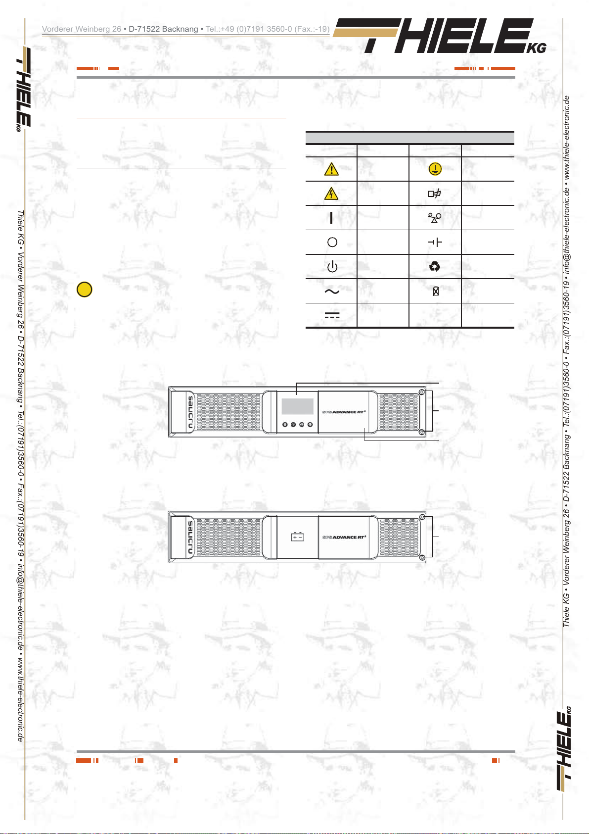
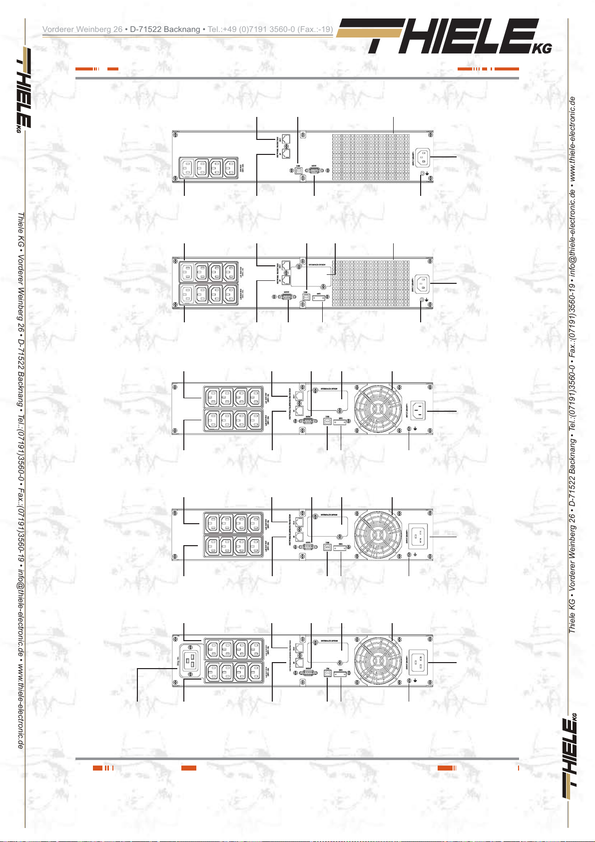
Figures 1 to 3 shows the illustrations of the equipment according
to the format of the enc losure and related to the power of t he
model. Neverth eless and due to the const ant evolution of the
product, sev e ral discr epa ncies or sma ll co ntr adict ions can aris e.
If you have any doubt, the labelling on the equipment will alwa ys
prevail.
checked. Act in accordance with the installation.
In the nameplate sticked in the equipment, all the data re-
i
ferred to the main features of the equipment can be
3. 1 .2. Legend corresponding to the
equipment view s.
Symbol and their meaning
Symbol Meaning Symbol Meaning
Warning Earth
Electrical shock Alarm silenced
UPS ON /
Battery test
UPS OFF Battery
UPS on Standby
or shutdown
Alternating (AC)
Direct (DC)
Tab la 1. Used symbology in the equipment and/ or this manua l. .
Control panel
with LCD
Fixing screws,
Plastic beauty
front
Overload
Recycling
Keep the UPS i
a well ventilated
place
Front virew ADVANCE RT
Front view battery module for ADV ANCE RT
Fig. 1. Front view models from 0,7 to 10 kVA and battery
modules for extended back up times.
Plastic beauty
front
Fixing screws,
Plastic beauty
front
Thiele KG • Vorderer Weinberg 26 • D-71522 Backnang • Tel.:(07191)3560-0 • Fax.:(07191)3560-19 • [email protected] • www.thiele-electronic.de
SALICRU
9
Page 10
Vorderer Weinberg 26 • D-71522 Backnang • Tel.:+49 (0)7191 3560-0 (Fax.:-19)
Thiele KG • Vorderer Weinberg 26 • D-71522 Backnang • Tel.:(07191)3560-0 • Fax.:(07191)3560-19 • [email protected] • www.thiele-electronic.de
Standard 750 a nd
1000 VA models
Standard 1500 VA and
(B1)models
IEC outlets
IEC outlets
"LS1"
IEC outlets
"LS2"
IEC outlets
"LS1"
Output connector, with Módem
/ ADSL / Fax / ... protection Fan
Input connector, for modem
/ ADSL / Fax / ... line
Output connector, with Módem
/ ADSL / Fax / ... protection
Input connector, for modem
/ ADSL / Fax / ... line
Output connector, with Módem
/ ADSL / Fax / ... protection
USB COM
port
RS232 COM
USB COM
port
RS232 COM
port
RS232 COM
port
port
protection cover
Connector for
external EPO
protection cover
Smart slot
Smart slot
Earth connection
for battery module
Fan
Earth connection
for battery module
Fan
IEC inlet for AC
power supply
IEC inlet for AC
power supply
Standard 2000 VA
model
IEC outlets
IEC outlets
2000 V A ( B 1) model
IEC outlets
IEC outlets
Standard 3000 VA and
(B1)model
"LS2"
"LS1"
"LS2"
"LS1"
Input connector, for modem /
ADSL / Fax / ... line
Output connector, with Módem
/ ADSL / Fax / ... protection
Input connector, for modem /
ADSL / Fax / ... line
Output connector, with Módem
/ ADSL / Fax / ... protection
USB COM
port
RS232 COM
port
USB COM
port
RS232 COM
port
Connector for
external EPO
Smart slot
protection cover
Connector for
external EPO
Smart slot
protection cover
Earth connection
for battery module
Fan
Earth connection
for battery module
Fan
IEC inlet for AC
power supply
IEC inlet for AC
power supply
IEC inlet for AC
power supply
Thiele KG • Vorderer Weinberg 26 • D-71522 Backnang • Tel.:(07191)3560-0 • Fax.:(07191)3560-19 • [email protected] • www.thiele-electronic.de
16A IEC outlets
Fig. 2. Rear view according to the model and power rate of
the equipments.
IEC outlets
"LS2"
Input connector, for modem /
ADSL / Fax / ... line
10
USB COM
port
Connector for
external EPO
Earth connection
for battery module
USER MANUAL
Page 11

Vorderer Weinberg 26 • D-71522 Backnang • Tel.:+49 (0)7191 3560-0 (Fax.:-19)
Battery module
The connec tio n of the bat tery module with the e quip men t
and/or with other module is done through the front. To do it,
it will be needed to remove the front plastic trim of all the racks, to
Thiele KG • Vorderer Weinberg 26 • D-71522 Backnang • Tel.:(07191)3560-0 • Fax.:(07191)3560-19 • [email protected] • www.thiele-electronic.de
have access to the connection connectors ready for this purpose.
Fig. 3. Rear view of the battery modules for extended back
up times.
3.2. Definition of the product.
3.2.1. Nomenclature.
SPS. 1 000.ADV RT (B 1) WCO “EE29503”
Toma tierra para
conexión con equ ipo
y con otro módulo de
baterías
MOD BAT ADV RT 2x6AB003 40A WCO “EE29503”
Note relative to the batter ies:
i
B0 and B1 acronyms stated the nomenclature rela t ed t o
batteries:
(B0) The equipment is supplied without batteries and
without accessories for them (screws and electrical
cables ).
Batteries are property of the client, and they will be
fitted out of the UPS case or cabinet.
Under request, it is possible to supply the acces-
sories (screws and electrical cables), needed to
install and connect the external batteries.
(B1) Equipment wit h extra battery char ger. The e quip-
ment is supplied without batteries and without ac-
EE* Special specifications of the cus tomer.
CO “Made in Spain” marking in the UPS and packaging (custom issues ).
W Neutral brand.
(B0) No batteries and no space to fit them in.
(B1 ) Equipment with extra charger and batteries out from UPS.
ADV RT Series of the equipment.
1000 Power in VA.
SPS Acronym for interactive UPS (Standby Power Systems) .
EE* Special specifications of the cus tomer.
CO “Made in Spain” marking in the UPS and packaging (custom issues ).
W Neutral brand.
40A Protection size.
003 Last three characters of the battery code.
AB Initials of the battery family.
6 Battery quantity in one string.
2x Quantity of strings in parallel. Omitted for one.
0/ Battery module without them, but the needed accessories
to install them.
ADV RT Series of the battery module.
MOD BA T Battery module.
cessories for them (screws and electrical cables),
corresponding to the stated batteries in the model .
Under request, it is possible to supply the acces-
sories (screws and electrical cables), needed to
install and connect the batteries.
For those equipments requested without batteries, the
acquisition, installation and connection of themselves
will always be done by client and under his responsibility.
Regarding the battery data of quantity, capacity and
voltage are stat ed in the battery label sticked beside the
nameplate of the equipment, respect this data and the
polar i ty of the batt e ry c o n n ec t i o n strictly.
Thiele KG • Vorderer Weinberg 26 • D-71522 Backnang • Tel.:(07191)3560-0 • Fax.:(07191)3560-19 • [email protected] • www.thiele-electronic.de
SALICRU
11
Page 12

Vorderer Weinberg 26 • D-71522 Backnang • Tel.:+49 (0)7191 3560-0 (Fax.:-19)
3.3. Descri pt io n a nd ope rat in g
This user's manual describes the installation and operating of
the Uninterruptible Power Supp ly (UPS) from SPS.ADV ANCE
RT series, for power ranges between 750 and 3000VA.
These Line-interactive equipments with pure sinewave output,
are designed to protect the most critical electronic devices
Thiele KG • Vorderer Weinberg 26 • D-71522 Backnang • Tel.:(07191)3560-0 • Fax.:(07191)3560-19 • [email protected] • www.thiele-electronic.de
against problems of the power supply lik e undervoltages, peaks,
brownouts, noise in the line and electrical mains fault.
Among other applications, we can quote, PCs, servers, workstations, and other IT networks devices.
The design allows both the rack-mounting assembling with 2U
height to be fitted in 19" cabinet, previous installation of the side
metallic suppor t with L shape and tower format by using the
plastic supports as a plinth.
The UPS has a front panel wit h LCD and four buttons (Star t up
switch , Silent/UPS test, Setting and Enter) allow an easy monitoring: Configuration and control, AC input line, inform about the
wiring fault and the load status. It also includes two LCD bar graphs,
one indicates the battery charge level and the other one the level of
the load connected at its output. Each bar is divided into five parts,
which each one is equivalent to 20% of the total value.
The equipment has four acoustic alarms (Back up time mode
-dischar ge of the battery-, low bat tery - end of back up time -,
overload and UPS fault). By means of the Silent/UPS test button
located at the front panel, the acoustic alarm can be deactivated
or to initiated the autot est procedure.
The SPS.ADVANCE RT equipments are fed from AC comm ercial mains and s upp ly AC energy at their o utp ut through the IEC
outlets installed at the rear side of the equipment. In case the
power supply is cor r ect, the load/s are fed throu gh the stabilizer
with «Boost» and «Buck» technology.
In case of mains fault or voltage and/or frequency out of the acceptable range, load/s will be fed from the batteries through the
inverter for a determined time, depending on the model, battery
charge level and the own load connected at the output.
For models higher than 1000 VA, it is possible to increase the
standard back up time of the equipments, by connecting additional
modules and/or to optimise the recharging time of the accumulators, by fitting chargers with better quality performances (B1).
All the power range has serial and USB communication ports for
communication and equipment control. The serial port supports
the direct co mmuni cati ons wi th a ser ver and t he proto col i s ac cording to a RS-232 interface.
Also, all models hav e RJ-45 connectors for modem / ADSL / Fax
line protection.
Likewise, the models over 1000 VA have:
Ŗ EPO connector, to install the option and external by the own
Ŗ Smart slot to install one of the following communication cards:
This manual is applicable to the standardized and stated models
in table 2.
principle.
user, of an emergency power off button.
AS-400 relay interface, with DB9 connection.
SNMP for controlling the equipment via Web.
Card for Internet or Intranet management.
3.3.1. Main features.
Ŗ Control by microprocessor with high reliability.
Ŗ Design of high frequency.
Ŗ Stabilizer with «Boost» and «Buck» technology.
Ŗ Selectable output range and line sensitivity.
Ŗ Cold start.
Ŗ Standard communication ports: RS-232 and U SB.
Ŗ Possible communication extend through the slot.
Ŗ Extended back up time by means of the battery modules for
models higher than 1000 VA.
Ŗ As an option, more powerful battery chargers, for models
highe r th a n 1000 V A.
Ŗ Protection again st overload, short- circuit and overtem pera-
ture.
Ŗ Design 2 in 1, as 19" rack with 2 U height or Tower.
Model Type
SPS.750.ADV RT
SPS.1000.ADV RT
SPS.1500.ADV RT
SPS.2000.A DV RT
SPS.3000.A DV RT
SPS.1500.ADV RT (B0 )
SPS.3000.A DV RT (B 0)
SPS.1500.ADV RT (B1)
SPS.2000.A DV RT (B1)
SPS.3000.A DV RT (B1)
Tab la 2 . Standardised models.
Large back up time with additional
Standard
No batteriesSPS.2000.A DV RT (B0)
charger
3.4. Options.
Depending on the selected configuration, the equipment can include any of the following options:
Thiele KG • Vorderer Weinberg 26 • D-71522 Backnang • Tel.:(07191)3560-0 • Fax.:(07191)3560-19 • [email protected] • www.thiele-electronic.de
12
USER MANUAL
Page 13
Vorderer Weinberg 26 • D-71522 Backnang • Tel.:+49 (0)7191 3560-0 (Fax.:-19)
3.4.1. Isolation transformer.
The isolation transformer, provides a galvanic isolation that allows isolating the output from the input complet ely.
The installation of an electrostatic shield between the primary
and secondary windings of the transformer provides a high level
of attenuation of the electrical noises.
The isolation tr ansform er can be i nstalle d at the in put or out put
of the UPS from SPS.ADVANCE RT s eries and it will always be
Thiele KG • Vorderer Weinberg 26 • D-71522 Backnang • Tel.:(07191)3560-0 • Fax.:(07191)3560-19 • [email protected] • www.thiele-electronic.de
located out from the equipment enclosure.
3.4.2. External maintenance manual
bypass.
The purpose of this option is to isola te electrically the equipment
from mains and critical loads, without breaking the power supply
to the loads. Therefore, in this way the maintenance or fixing
tasks can be done in the equipment with no interruption on the
power supply energ y to the pr otec ted sys tem, at the s ame t ime
that unnecessary risks are avoided to the technical staff.
3.4.3. Integrati on i n IT ne twor k s b y
means of the SNMP adaptor.
The big IT systems base d on LANs and WANs that integrate
servers with different platforms, they have to include an easy
way of controlling and management at the manager system disposal. This facilit y is got through the SNMP ad aptor, which is
well-known by the main software and hardware manufacturers
The available SNMP optio n for SPS.ADVANCE RT series is a
card to be inserted into the slot that the UPS has in its rear side.
The connection of the UPS with the SNMP is internal meanwhile
the connect ion bet ween the SN MP and the IT net work is d one
through a RJ45 connector 10 base.
3.4.4. AS400 card.
See section 4.3.6.3.
3.4.5. MODBUS protocol.
The big IT systems based on LANs and WANs, many times they
require that the c ommunic ation wit h any device ha s to be integrated in the IT network and it has to be done by means of an
industrial standard protocol.
One of the most used industrial standard protocols in the market
is the MODBUS protocol. SPS.ADVANCE RT series is also
ready to be integrated in this type of environments through the
external “SNMP TH card” device with MODBUS protocol.
Thiele KG • Vorderer Weinberg 26 • D-71522 Backnang • Tel.:(07191)3560-0 • Fax.:(07191)3560-19 • [email protected] • www.thiele-electronic.de
3.4.6. Extensible rai l k it f o r ra ck c abi ne t
assembling.
There is available only one m odel of teles copic g uide kit for all
models, suitable for any type of rack cabinet.
These guides allow installing any unit of the SPS.ADVANCE RT
equipment and their possible battery modules, in case of extended back up times, as it was a rack with its respective cabinet.
SALICRU
13
Page 14

Vorderer Weinberg 26 • D-71522 Backnang • Tel.:+49 (0)7191 3560-0 (Fax.:-19)
4. Installation.
Ŗ Check the Safety instructions, from section 1.2.3.
Ŗ Check that the data in the namepla t e a re the requi red b y the
Ŗ A wrong connection or manoeuvring, can make faults in the
Thiele KG • Vorderer Weinberg 26 • D-71522 Backnang • Tel.:(07191)3560-0 • Fax.:(07191)3560-19 • [email protected] • www.thiele-electronic.de
Ŗ
Ŗ
Ŗ
Ŗ Under request, we are able to supply a manual bypass panel.
Ŗ
4.1. T o be considered in the
Ŗ All the range ha s a power cord with p lug for input and IEC
Ŗ Cross cable se ction of the bypa ss, input and output li nes,
Ŗ Protections of th e switchgear panel, will h ave the following
Ŗ In the nameplate of the equipment there are only printed the
Ŗ If it is added peripherals to the input and/or output like trans-
Ŗ
installation.
UPS and/or loads connec ted to itself. Read caref ully the instructions of this manual and follow the stated steps in the
established order.
The equipments c an be installed and used by p ersonnel with no specific training just with the help of this
«Manual».
All connections of the equipment including the control
(interface, remote panel, ...), will be done with the
switches at rest and no voltage present (UPS power supply
switch to «Off») .
Never forget that the UPS is an electrical energy generator, so the user has to take the needed cautions
against direct and indi rect conta cts.
Battery circuit is not isolated from input voltage. Hazardous voltages can be found out between the ba ttery
terminals and earth. Check that there is not input v oltage before doing any intervention on them.
installation.
outlets for output , a s connection parts for power. The rest of
connections are done through the connectors, including the
connection of the equipment with the battery module (it is not
available on equipments belo w 1000VA) .
will be calculated from the currents stated in the nameplate
of each equipment, and respecting the Local and/or National
Low Voltage Electrotechnical Regulations.
features:
For input line, t ype B for RCD devi ces and C c haracter-
istic for circuit breakers.
For the outpu t (load fee ding), C characteri stic for c ircui t
breaker.
Regarding the size, they will be as minimum to the currents
stated in the nameplate of each UP S.
nominal currents as it is stated in the safety standard EN-IEC
62040-1. To calculate the input current, the power factor and
the efficiency of the equipment have been considered.
Overload conditions are considered as nonpermanent and
exceptional operating mode.
formers or autotransformers to the UPS, the currents stated in
the own nameplates of those elements has to be considered
in order to use the suitable cross sections, by respecting the
Local and/or National Low Voltage Regulation.
When an equipment incorporates a galvanic isola tion
transformer, as standard, as an option or either in-
stalled by yourself, either at the UPS input or output or at all
of them, protections against indirect contact has to be fitted in
(residual current device) at the output of each transformer,
because due to its specification of isolation it will prevent the
triggering of the protections fitted in the primary of the transformer in case of el ectrica l s hock in the secon da ry ( o utpu t o f
the isolation transformer) .
Ŗ Remind you that all external isolation transfor mers already
installed or supplied from factory, has the neutral of the secondary connected to earth by means of a cable bridge between both terminals. If it were required an isolated output
neutral, remove this cable bridge, keeping the precautions
stated in the respective local and/or national low voltage regulations.
Ŗ All the UPSs have batteries in sid e the s ame r ack e nc losur e
of the equipment. Battery protection is by means of fuse and
internal, so it is no accessible by the end-user.
Battery mo dule s have internal prote cti ons by fu se, and they
are not accessible by the end-user too.
4.2. Reception of the equipment.
4.2.1. Unpacking, content checking and
inspection.
Ŗ To unpack, see section 4.2.3.
Ŗ On receiving the device, make sure that it has not suffered
any damage in transport (impact, drop, ...) and its features
correspond with the ones in the order, so it is recommended
to unpack the UPS and make a first visual inspection.
Ŗ In case of observing damages, make all pertinent claims to
the transport agency or in their lack to our company.
Never start up an equipment when e xternal damages
can be observed .
Ŗ Also check that the data in the nameplate sticked in the pack-
aging and in the equipment, correspond to the ones stated
in the order, so it is required to unpack it (see section 4.2.3).
Otherwise, make a nonconformity as soon as possible, by
quoting the serial num ber of the e quip ment and r eferenc es
in the delivery note.
Ŗ Check the contents of the packa ging. Depending , if we are
checking an equipment or battery module, the contents will
vary.
Equipment:
– The own equipment.
– Quick guide in paper.
– 1 power cord for input connection -schuko plug and
IEC connector-.
– 2 cables fo r outp ut con nectio n with IE C connect ors.
– 1 communication cable USB.
– 4 plastic pieces to be joint two by two to fit the UPS
in vertical position.
– Two metallic pieces with L shape to adapt the equip-
ment to rack f o rmat.
Battery module:
– The own equipment.
– 1 connection cable for protection earth, to link the
equipment and module.
– 2 plastic pi eces to adapt the su pport s of vertical in -
stallation of the UPS and batteries (battery modules
for equipments up to 3 kVA only).
– 1 metallic piece and bolt to joint the battery module
with the equipment on tower f o rmat.
Thiele KG • Vorderer Weinberg 26 • D-71522 Backnang • Tel.:(07191)3560-0 • Fax.:(07191)3560-19 • [email protected] • www.thiele-electronic.de
14
USER MANUAL
Page 15

Vorderer Weinberg 26 • D-71522 Backnang • Tel.:+49 (0)7191 3560-0 (Fax.:-19)
Ŗ Once the reception is finished, it is advisable to pack the UPS
4.2.2. Storage.
Ŗ Storage of the equip ment will be do ne in a dry p lace, safe-
Thiele KG • Vorderer Weinberg 26 • D-71522 Backnang • Tel.:(07191)3560-0 • Fax.:(07191)3560-19 • [email protected] • www.thiele-electronic.de
Ŗ
Ŗ After this period of time, connect the equipment to mains and
Ŗ Finally, shutdown the equipment, disconnect it and fit the U P S
Ŗ Do not store the devices where the ambient temperature ex-
4.2.3. Unpacking.
Ŗ The packaging of t he equipment co nsists of a cardb oard
Ŗ Proceed as follows:
and the battery module/s again till its commissioning in order
to protect it against mechanical shocks, dust, dirt, etc...
guard from rain, prote cted fr om dust , water jets or ch emic al
agents. It is advisable to keep the equipment and the battery
pack/s, into their original packages, which have been designed to assure the ma xi mum protec tion d uring t he trans port and storage.
In general and less in sp ecial cases, the UPS has
sealed lead-calcium batteries and should not be
stored for more than 12 months (see the date of the last
charge of the bat teries, noted on the lab el adhered to the
device packaging or on the battery unit) .
together with battery module/s, if any, start it up according to
the instructions described in this manual and charge them for
2 hours from floating level .
and batteries in their original packaging, noting th e n ew b attery charge date on each respective label.
ceeds above 50ºC or below -1 5ºC, otherwise it may degrade
the electrical characteristics of the batteries.
enclosure, expanded polystyrene corner pieces (EPS) or
polyethylene foam (EPE), polyethylene sleeve and band,
all of them are recyclable m aterials; therefore th ey should
be disposed according to current regulations. We recommend to keep the packaging in case its use is necessary
in the future.
Cut the strips of cardboard enclosure.
Remove the accessories (cables, supports, ... )
Remove the equipment or battery module from the pack -
aging, keeping in mind that the it is needed the help of a
second person depending on the weight of the model.
Remove the protect ion cor ners from th e packagin g and
the plastic bag.
Do not leave the plastic b ag at th e ch ild ren h and ,
due to the risk that it means.
Check the equipment before proceeding and in case
damages where confir med, contact w ith the supplier or
in lack of it with our firm.
tation in the steps to fo llow and they are not particul ar for
any model, although in practice, the actions to make are the
same for all models.
Nevertheless when the generic illustrations differ, there will
be new illustrations to show it.
Ŗ All the instructions relating to connections will detailed later
on, less those ones regarding the battery connection. Therefore, this section will only describe the works linked with the
assembling.
4.2.4. 1 . Removing or fitting the beauty cover.
"D"
"C"
"D"
4.2.4. Vertical assembling -tower type- or
rack.
Ŗ All the UPSs from SPS. ADVANCE RT series are designed
to assemble the equipment as tower format -vertical position
of the equipment- or rack -horizontal position- for its installation in 19" cabinets.
Follow the instructions stated in the sections related to any
of both possibilities, attending the particular configuration of
your equipment.
Ŗ Figures from 4 to 9 show as an example t he grap hic s of an
equipment. These illustrations are only for help and orien-
SALICRU
Thiele KG • Vorderer Weinberg 26 • D-71522 Backnang • Tel.:(07191)3560-0 • Fax.:(07191)3560-19 • [email protected] • www.thiele-electronic.de
Fig. 4. Taking out the beautiful front cover.
15
Page 16

Vorderer Weinberg 26 • D-71522 Backnang • Tel.:+49 (0)7191 3560-0 (Fax.:-19)
Ŗ To take out the beautiful front cover, proceed as follows (see
figure 4) :
Remove the two fi xing screws "C" fr om beautifu l plastic
front cover.
Move the front cover to "D" direction, by applying a hard
and moderated knock on its side ( side without scre ws) , t o
free the trim entered into the metallic frame.
The front is free, but stil l joint to the equi pment throug h
the connection bus of the control panel.
Thiele KG • Vorderer Weinberg 26 • D-71522 Backnang • Tel.:(07191)3560-0 • Fax.:(07191)3560-19 • [email protected] • www.thiele-electronic.de
Ŗ To put the beautiful front cover back, pro c e e d in t h e revers e
way to its removing.
4.2.4.2. Rotation of control panel with LCD
panel.
Take out the beautiful front
cover a ccordin g t o sect ion
4.2.4.1
"B"
90º
"A"
"C"
Fig. 5. Rotation of the control panel with LCD over the beau-
tiful plastic front cover.
Ŗ To make easier the message reading when the equipment is
vertically installed, it is advisable to rotate 90º clockwise the
control panel with LCD (see figure 5).
Ŗ Also, it is advise d to rot ate t he c o ntro l pa nel, i f any tower t y pe
equipment requires to be assembled as ra ck. Consider that the
rotation of the control panel will be counter clockwise.
Ŗ Proceed as follows:
Remove the beautiful front cov er as it is stat ed in section
4.2.4.1
Slightly open the nails of the fo u r trims th a t hold the con-
trol panel with LCD to the b eautiful fron t cover to free it
and push inward "A" to separate both parts.
Rotate it 90 º on clockwise "B" an d insert it again into
the beautiful front c over till c li ck i t "C". Check the c or re c t
closing of the fixing nails.
Put the beaut iful fr ont c over back , in t he revers e way as
its removing (see section 4 .2.4.1).
4.2.4.3. Vertical assembling -tower type-.
Ŗ Rotate the control panel according to section 4.2.4.2.
Ŗ Take the 4 plastic pieces "A" with an gl e sh ap e sup p lie d wit h
the equipment and j oint t he m t wo by t wo t ill o bta in t wo su p ports or stabilizers "B".
Ŗ Put the UPS vertical between the two stabilizers supports "B"
(see figure 6).
"B"
Fig. 6. Vertical -tower type- assembling.
"A"
"A"
4.2.4.4. Vertical assembling -tower type- , with
extended back up time (battery module).
Ŗ The description of this section is based on an equipment
with only one battery module (see figure 7). For a higher
quantity of modules proceed to the connection among them.
Ŗ Rotate the control p anel of t he e qui pm ent ac c or di ng to se c -
tion 4.2.4.2.
Ŗ Take the 4 plastic pieces "A" with a ngle s hap e and sup plie d
with the UPS and the two su pplied wi th the bat tery mo dule
"B", and joint them till obtain two supports or stabilizers "C" to
hold the equipment and battery module.
Ŗ Put the UPS and ba ttery module on vertical position between
the stabilizers supports "C" .
Ŗ Fix the "D" metallic pie c e that jo int UPS and battery module
by means of the supplied screws "E".
Ŗ Regarding the connections of the UPS with the ba ttery module,
make the following steps, but reading section 4.3.3 previously:
Connec t the supplie d earth jo int cable "F ", between the
UPS and battery module.
Thiele KG • Vorderer Weinberg 26 • D-71522 Backnang • Tel.:(07191)3560-0 • Fax.:(07191)3560-19 • [email protected] • www.thiele-electronic.de
16
USER MANUAL
Page 17

Vorderer Weinberg 26 • D-71522 Backnang • Tel.:+49 (0)7191 3560-0 (Fax.:-19)
Remove the beautif ul front cover of the equipme nt and
battery module, as it is described in section 4.2.4.1.
Take the extensible cable w ith co nnec tor "H " of the bat-
tery module and connect it with the "G" connector of the
equipment.
To connect it with other battery modules, there is the "J"
connector. Take the extensible cable with "H" connector
of the beside battery module and connect it to the "J" connector of the previous one. Repeat the same steps for a
high quantity of modules.
Thiele KG • Vorderer Weinberg 26 • D-71522 Backnang • Tel.:(07191)3560-0 • Fax.:(07191)3560-19 • [email protected] • www.thiele-electronic.de
"F"
"C"
"A"
"D"
"E"
"B"
"A"
"J"
"G"
"K"
Fig. 7. Model in vertical -tower type- assembling with ex-
tended back up time (battery module).
"H"
"K"
In the side of each front cover, there are the "K" trims as a
notch to go the cables through it with the ba ttery modules.
Break the needed trims to pass the connection bus.
Put the beaut iful front c over back of the equ ipment and
battery module, as it is stated in section 4.2.4. 1.
4.2.4.5. 19" rac k cab ine t a ssem bli ng.
Ŗ All models can be installed in a 19" rack cabinet, attending
the height of each one of them is 2 units.
Ŗ Proceed as follows (see figure 8 ):
Fix both adaptor ang les "A" of the equipment as rack, to
its side by means of the supplied screws.
Put a UPS in a rack cabinet, it is needed to ha v e the side
internal rail as support mode "C". In lack of them and
under request, a rail s can be su pplied a s a guide, to be
Thiele KG • Vorderer Weinberg 26 • D-71522 Backnang • Tel.:(07191)3560-0 • Fax.:(07191)3560-19 • [email protected] • www.thiele-electronic.de
SALICRU
17
Page 18

Vorderer Weinberg 26 • D-71522 Backnang • Tel.:+49 (0)7191 3560-0 (Fax.:-19)
installed by the end u ser. Make the a ssembling at the
required height, assuring the correct torque of the fixing
screws.
Face the equipment over the ra ils and enter it t o the bottom.
Depending on the model of the equipment and as a result
of the weight, it is recommended to make the installation
works by two persons, and even more when they are
done on the top and bottom of the cabinet.
Fix the equipment to the frame of the cabinet by means
of the screws "B".
Thiele KG • Vorderer Weinberg 26 • D-71522 Backnang • Tel.:(07191)3560-0 • Fax.:(07191)3560-19 • [email protected] • www.thiele-electronic.de
"C" "B"
"A""C"
"B"
Fig. 8. 19" rack cabinet assembling.
4.2.4.6. 19" rack cabinet assembling, with
extended back up time (battery module).
Ŗ This section describes a single equipment with only one bat-
tery module (see figure 9). For higher quantity of modules
reproduce the connection procedure among them.
Ŗ All models can be installed in a 19" rack cabinet, attending
the height of each one of them is 2 units.
Ŗ Proceed as follows:
Fix both adaptor ang les "A" to the equipment and to the
battery mod ule as rack, on their sid e, by means of the
supplied screws.
"F"
"K"
"H"
"G"
"J"
"K"
Fig. 9. Model in rack-mounting f orma t in 19" cabinet, with
extended back up time (battery module).
Put a UPS in a rack cabinet, it is needed to ha v e the side
internal rails as support mode "C". In lack of them and
under request, a universal rails can be supplied as a
guide, to be installe d by the en d user. Make the asse mbling at the required height, assuring the correct torque of
the fixing screws.
Face the equipment over the rails and enter it to the bottom.
Proceed in the same way for the battery module.
Thiele KG • Vorderer Weinberg 26 • D-71522 Backnang • Tel.:(07191)3560-0 • Fax.:(07191)3560-19 • [email protected] • www.thiele-electronic.de
18
USER MANUAL
Page 19
Vorderer Weinberg 26 • D-71522 Backnang • Tel.:+49 (0)7191 3560-0 (Fax.:-19)
Ŗ Regarding the connections of the UPS with the battery
Thiele KG • Vorderer Weinberg 26 • D-71522 Backnang • Tel.:(07191)3560-0 • Fax.:(07191)3560-19 • [email protected] • www.thiele-electronic.de
4.3. Connection.
Ŗ Cross cable sec tion use d in the power sup ply of the
Ŗ Installation will have the suitable input protections sized to
Ŗ Output protection will be done with a circuit breaker of C char-
Ŗ To insert the option cards, it is needed to remove the fixing
4.3.1 . Connection of input.
Ŗ As this is a device with class I protection against elec-
Ŗ Take the power cord with schuko plug and IEC connector and
Depending on the weight of model o f the equipmen t and
battery module, it is recommended to make the installation works by two pe rsons.
Fix the equi pment to t he frame of t he cab inet by means
of the screws "B".
module, make the following steps, but reading section 4.3.3
previously:
Connec t the supplie d earth jo int cable "F ", between the
UPS and battery module.
Remove the beautif ul front cover of the equipme nt and
battery module, as it is described in section 4.2.4.1.
Take the extensible cable w ith co nnec tor "H " of the bat-
tery module and connect it with the "G" connector of the
equipment.
To connect it with other battery modules, there is the "J"
connector. Take the extensible cable wit h "H " co nne ctor
of the beside battery module and connect it to the "J" connector of the previous one. Repeat the same steps for a
high quantity of modules.
In the side of each front cover, there are the "K" trims as a
notch to go the cables through it with the ba ttery modules.
Break the needed trims to pass the connection bus.
Put the beaut iful front c over back of the equ ipment and
battery module, as it is stated in section 4.2.4. 1.
equipment and loads to feed, will be sized according
to the nominal current stated in the nameplate sticked on the
equipment, by res pecting th e Low Voltage Electrotech nical
Regulations or norms of the corresponding country.
the current of the e quip me nt and st ated i n the n ame plate of
the equipment (residual current devices type B and circuit
breaker with C characteristic or any other equivalent one).
Overload conditions are considered as a nonpermanent an
exceptional operating mode, so these currents will not be
kept in mind when sizing the prot ections.
acteristic or any other equivalent one.
The equipments c an be installed and used by p ersonnel with not specific training, just with only help of
this «Manual».
screws of the smart slot and the own cover.
When finalising the corresponding tasks, the cover will be in-
stalled and its fixing screws again.
tric shocks, it is e ssent ial to ins tall a prote cti ve ear th
conductor (connect earth(
fore connecting the power supply to the input pow er block.
connect the IEC connector to the UPS inlet. Next insert the
schuko plug to the AC mains outlet.
)). Connect the conductor be-
4.3.2. Connection of the IEC outlets.
Ŗ As this is a device with class I prot ection against elec-
Ŗ All the equipments have female IEC outlets, in greater or lesser
Ŗ If besides of the critical loads, it is required to connect lag-
tric shocks, it is essential to install a protective earth
conductor (connect earth(
the terminal, befor e connecting the power supply to the input
power block.
numbers depending on the power rate of the equipment:
Models up to 1 kV A: 1 group of 4 IEC outlets of 10A.
Models of 1,5 and 2 kVA: 2 groups of 4 IEC outlets of 10A la-
belled as LS1 and LS2, which can be set through the control
panel and/or Win Power.
Models of 3 kVA: 2 groups of 4 IEC outlets of 10A labelled
as LS1 and LS2, which can be set through the control panel
and/or Win Power, plus a IEC connector of 1 6A.
Loads can be connect ed to the IEC outlets , mean-
while the features of the e quipmen t and IEC outlets limitations are n ot exceed ed, ot herwise there will be
sudden blackouts in the power supply of the connec ted
loads at the output.
ging loads of high consumption, like laser printers or CRT
monitors, the inrush currents o f these peripherals will be kept
in mind in order to avoid blocking the equipment under the
worst conditions.
It is better to not connect the loa ds of this kind, due to the high
quantity of energy resources that take from the UPS.
)). Connect the conductor to
4.3.3. Connectio n o f the e xtern al
batteries (extended back up time).
Ŗ As this is a device with class I protection a gainst elec-
Ŗ
Ŗ To connect the batteries with the equipment, follow the de-
Ŗ All the standard UPSs h ave batteries in the same e nclosure,
Ŗ
Ŗ
Ŗ Connection terminals of external batteries with the equip-
Ŗ For battery c onnection with the equip ment, follow the stated
tric shocks, it is essential to install a protective earth
conductor (connect earth(
the terminal, befor e connecting the power supply to the input
power block.
To not respe c t th e state d indications in this section and the safety instructions 1.2.3 means a
high risk of electrical discharge and even the death.
scribed steps in sections 4.2.4.4 and 4.2.4.6.
less the B0 and B1 (not available for models equal or be low
1kVA). Battery protection is done by internal fuses and not accessible for the end-user.
Battery mo dules have internal protections for th e batteries
too and they are not accessible for the end-user.
IMPORTANT FOR SAFETY: In case of installing the
batteries by yourself, the accumulators has to be pro-
vided with a t wo pole cir cuit breaker protec tion sized to t he
features stated in table 3.
Before starting the connection between the battery module/s and the equipment, check that the
equipment and loads are in "Off" position.
Likewise when batteries are installed by the own user,
the fuse or switch has to be turned off.
ment are done with a po larised Anderson c onnector. This
connector is not available in models up to 1kVA.
steps in sections 4.2.4.4 and 4.2.4. 6, keeping in mind the model.
)). Connect the conductor to
Thiele KG • Vorderer Weinberg 26 • D-71522 Backnang • Tel.:(07191)3560-0 • Fax.:(07191)3560-19 • [email protected] • www.thiele-electronic.de
SALICRU
19
Page 20
Vorderer Weinberg 26 • D-71522 Backnang • Tel.:+49 (0)7191 3560-0 (Fax.:-19)
Ŗ Each battery module is independent for each equip-
SPS.1500.ADV RT
Thiele KG • Vorderer Weinberg 26 • D-71522 Backnang • Tel.:(07191)3560-0 • Fax.:(07191)3560-19 • [email protected] • www.thiele-electronic.de
SPS.2000.A DV RT
SPS.3000.A DV RT 60
Tab la 3 . Specifications of the protection between the equipmen t and
4.3.4. Connection of main input earth
Ŗ As this is a device with class I protection a gainst elec-
Ŗ Make sure that all the loads connected to the UPS are only
Ŗ All terminals identified as earth bonding (
4.3.5. EPO term ina ls in UP Ss > 1kVA
Ŗ All UPSs have two terminal to install an external button, for
Ŗ As an illustration mode, figures A and B, it is shown a co n-
Ŗ By default, the equipment is supplied from factory with the
ment. It is completely forbidden to connect to equip-
ments to the same battery module.
Minimum features of fast
Voltage
floating
DC (V)
250
fuse type
Current (A)
50
60
Model
battery module.
Batteries
(U
elemento
/ U
U
nominal
(12 V x 3 ) =
36 V / 41.4 V
(12 V x 6 ) =
72 V / 82.8 V
x Nº) =
terminal ( ) and the earth bonding
terminal ( ).
tric shocks, it is e ssent ial to ins tall a prote cti ve ear th
conductor (connect earth(
)). Connect the conductor to
the terminal, before connecting the power supply to the input
power block.
connected to the protective earth bonding terminal (
). The
fact of not restricti ng the earthing of the load or load s and/or
the batteries case/s or cabinet/s to this single point will creat e
a return loops to earth which will affect the quality of the supplied power.
), are joined
together, t o the main prot ective earthing terminal (
) and
to the frame of the device.
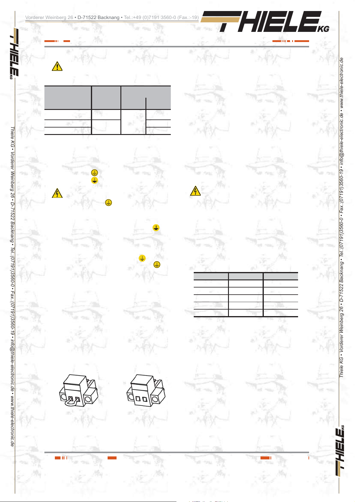
(Emergency Power Off).
Emergency Powe r Off (EP O) .
nector of two pins.
EPO circuit as open (NO). So, the UPS will break the output
power supply, emergency power of f, when opening t he circuit:
Either by removing the female connector inserted in the
plinth. Th is co nn ect o r ha s a cab le b rid ge t o clo se th e ci rcuit (Fig. A).
Ŗ Through the c ontrol panel, it can be selecte d the reverse
functionality, normally closed (NC ) .
Less punctual cases, it is not recommended to use this type
of connection due to the function of the EPO button, because
it would not work in case of any of the two cables that goes
from the button to the UPS were cut (damaged).
On the other hand this failure would be immediately detected
in the normally open EPO type, with the inconvenience of
the sudden break in the p ower supp ly to the lo ads, but w ith
a complete guara ntee of the function ing of the emergenc y
power off.
Ŗ To restore the normal operating mode of the UPS, the con-
nector with the cable bridge has to be fitted back in the terminal
strip or to dea ctiva te the E P O button and la ter on t o ca ncel the
EPO status in the control panel . The equipment will be operative.
4.3.6. Communication port.
4.3.6.1. RS232 and USB interface.
Ŗ Communication line (COM) is a v ery low voltage ci rcuit
Ŗ RS232 and USB inter fac es ar e us ed by t he m o nitor i ng s oft-
Ŗ It is not possible to use both ports at the same time.
Ŗ Signal pin-out of the DB9 connector are shown in table 4. In
Tab la 4 . Pin-out o f the RS232 and o ptocou plers dr y contac t in the
Ŗ USB communication port is compatible with the USB 1 .1 pro-
of safety. To preser ve the quality, it has to be installed
separate from other lines tha t have dangerous volta ges (energy
distribution line).
ware and firmware updating.
the connector, the RS-232 signal and dry contacts through
optocouplers ca n b e f ou nd .
RS232 port consists in a serial data transmission, so an important quant ity of informat ion can be sent thr ough a com munication ca ble of 3 wi re s.
Pin # Description Input / Output
1 (*) Low battery Output
2RXDInput
3TXDOutput
5 (**) GND / common -
8 (*) Mains fault Output
(*) No rmally open dr y contacts (N O), maximum appli cable voltage
and current is 30V DC and 1A.
(**) GND for RS232 and common for dry contacts.
DB9 connector.
tocol for comm un ica ti on s oftwa re .
Fig. A Fig. B
Or by turning on the external button installed and be-
longing to the end-user. The connection in the button has
to be in normally closed because it will open the circuit
when turning it on.
20
4.3.6.2. Smart slot.
Ŗ UPSs have a unique slot, hidden rea r the cov e r s tat ed in the
views of the equipmen t as " S mart slot", and allows insertin g
any of the following options cards:
SNMP for control via Web.
Remote UPS management through Interne t or In tranet.
AS400 (for more details see the next section).
Ŗ For more information, co ntact with o ur S.T.S or our nearest
distributor.
USER MANUAL
Thiele KG • Vorderer Weinberg 26 • D-71522 Backnang • Tel.:(07191)3560-0 • Fax.:(07191)3560-19 • [email protected] • www.thiele-electronic.de
Page 21

Vorderer Weinberg 26 • D-71522 Backnang • Tel.:+49 (0)7191 3560-0 (Fax.:-19)
4.3.6.3. AS400 Interface with DB9 output
Ŗ Communication line (COM) is a very low voltage circuit
Ŗ UPS has a dry cont act card for the AS4 00 communi cation
Thiele KG • Vorderer Weinberg 26 • D-71522 Backnang • Tel.:(07191)3560-0 • Fax.:(07191)3560-19 • [email protected] • www.thiele-electronic.de
Ŗ The most comm on use of this type of ports is to provide the
Ŗ For more information, c ontact wit h our S.T.S or our nearest
UPS fault 1 Output
General alarm 2 Output
Ground (GND) 3 Input
Common 5 Input
Bypass 6 Output
Low battery 7 Output
UPS "On" 8 Output
AC mains fault 9 Output
(option).
of safety. To preser ve the quality, it has to be installed
separate from other lines tha t have dangerous voltages (energy
distribution line).
protocol, it provides digital signals in a free potential way, with
a maximum app licable voltage an d current of 240 V ac or
30 V dc and 1A. Pin-out of the DB9 connector are stated in
figure 10 and detailed in table 5.
needed information for the closing file software.
distributor.
UPS fault
General alarm
Ground (GND)
Common
Fig. 10. AS400 dry contact pin-out.
Description Pin-out Input/output
Bypass
Low battery
UPS on
AC mains fault
4.3.7. Software.
Ŗ Free software download - WinPower .
WinPower is a UPS monitoring software, which makes a
user-friendly interface of monitoring and management. This
software supplies an auto Shutdown for a system based on
several PCs in case of an electrical blackout. With this software, the end-users can monitor and manage any UPS in the
same IT network, through the RS 232 or USB communicat ion
port, never mind the distance between them.
Fig. 11. Main screen of the monitoring software .
Ŗ Installation procedure:
Go to website:
http://support.salicru.com
Choos e th e op erat ing p lat fo rm t hat yo u nee d an d fol low
the instructions described in the web site to do wnload the
software.
When downloading the needed files from Internet, enter
the following licence to install the software:
511C1-01220-0100-478DF2A .
When the computer is rebooted, WinPower software will be
shown as an icon with plug shape and green colour in the
system tray, near the clock.
Tab la 5 . AS400 dry contacts alarms.
Installation.
Ŗ Remove the screws that fix the protection cover of the slot of
the equipment and the own cover.
Ŗ Take the AS400 card and insert i t into the sm ar t slot. Ma ke
sure that it is well connected, so the resistance that the own
connector i nsi de the sl ot ma k es h as to be o v e rcome .
Ŗ Fix the card with the previous removed screws.
Ŗ Connect the DB9 connector from AS400 with the peripheral
to be communicated.
4.3.6.4. Protectio n ag ain st tr ans ient v olta ges f or
modem / ADSL / Fax / ... lines.
Ŗ Communication line (COM) is a v ery low voltage circuit
of safety. To preser ve the quality, it has to be installed
separate from other lines tha t have dangerous voltages (energy
distribution line).
Ŗ Connect the m ain lin e for the m od em / ADS L / Fax /... to the
RJ45 connector of the equipment, labelled as "Input".
Ŗ Connect the own modem / ADSL / Fax /... to RJ45 connector
of the equipment, labelled as "Output" .
SALICRU
4.3.8. Considerations before
commissioning with load
connected.
Ŗ It is recommended to charge the batteries for 2 hours
Ŗ
Ŗ
Ŗ Although the equipment can work without charging the bat-
Ŗ Do not start up the equipment and loads completely till
as minimum before using the UPS for first time. When
supplying volt age to the eq uipmen t, the bat ter y charger w ill
automatically work.
(B1) equipments with extended back up time has a
battery charger with higher quality performances. It is
recommended to charge the batteries for 2 hours as minimum before using the UPS for first time .
Nevertheless, those equipments with extended back
up time and with no additional battery charger , it s rec-
ommended to charge the batteries of each battery module for
2 hours.
teries during the stated time without any problem, the risk of
a long blackout has to be valued during the first operating
hours and the available autonomy time in the UPS.
chapter 6 states it.
21
Thiele KG • Vorderer Weinberg 26 • D-71522 Backnang • Tel.:(07191)3560-0 • Fax.:(07191)3560-19 • [email protected] • www.thiele-electronic.de
Page 22

Vorderer Weinberg 26 • D-71522 Backnang • Tel.:+49 (0)7191 3560-0 (Fax.:-19)
Nevertheless, when it is done, it will be done gradually to
avoid any problem, as minimum in the first commissioning.
Ŗ If inductive loads with big inrush current apart from sensi-
tive ones are required to be connec ted like laser printers or
CRT monitors, keep in mind the start inrush currents of these
peripherals in order to avoid that the equipment becomes
blocked under the worst conditions.
It is better to not connect the loa ds of this kind, due to the high
quantity of energy resources that take from the UPS.
Thiele KG • Vorderer Weinberg 26 • D-71522 Backnang • Tel.:(07191)3560-0 • Fax.:(07191)3560-19 • [email protected] • www.thiele-electronic.de
22
Thiele KG • Vorderer Weinberg 26 • D-71522 Backnang • Tel.:(07191)3560-0 • Fax.:(07191)3560-19 • [email protected] • www.thiele-electronic.de
USER MANUAL
Page 23
Vorderer Weinberg 26 • D-71522 Backnang • Tel.:+49 (0)7191 3560-0 (Fax.:-19)
5. Operating.
5.1. Start up.
5.1.1. Controls before commissioning.
Thiele KG • Vorderer Weinberg 26 • D-71522 Backnang • Tel.:(07191)3560-0 • Fax.:(07191)3560-19 • [email protected] • www.thiele-electronic.de
Ŗ Make sure that all the connections have been made prop-
Ŗ Check that the UPS is turned Off (shutdown).
Ŗ Be sure that all the loads are turned «Off».
Ŗ It is very important to proceed in the established order.
Ŗ For UPS view, see figures 1 to 3.
5.2. UPS start up and shutdown.
5.2.1. Initial UPS start up.
Ŗ Check that the power supply connection is correct.
Ŗ Connect the power cord from UPS input to mains power
Ŗ Press over the start up key
Ŗ Check that there are not any alarm or warning activated in the
Ŗ In case of having battery modules connected to the equip-
Ŗ To change or modify other factory preset values, consult sec-
Ŗ In the initial start up, the UPS auto-senses the input fre-
5.2.2. UPS start up, with mains present.
Ŗ For the daily start up of the equipment, press over the start up
Ŗ Fan will be started u p and the LCD from control pane l will
Ŗ After several seconds, the UPS is established on "NORM"
erly, respecting the labelling of the equipment and the instructions of chapter 4.
Turn off the connected loads before starting up the
UPS , and start up th e loads one by one, when th e
UPS is started up only. Before shutdown the UPS, check all
the loads are out of service (Off).
supply. The LCD panel lights and shows the UPS status ,
"STBY" (Wait mode).
for more than 3 seconds. The
UPS will shift to "NORM" mode (Line mode ) .
UPS screen and in case of them fix them before proceeding
(consult the troubleshooting guide ).
ment, it is needed to set the complete system (UPS - quantity
of battery modules), see section 6.1.6.4.
tion 6 of this document.
quency and established it as the standard one.
In extreme cases can happen, although is almost not pos-
sible, that the mains frequency is very high or low from the
nominal and takes as a default value t he wro ng o ne. Chec k
the frequency in the control panel and repeat the procedure if
this circumstance wo uld occur.
key for more than 3 seconds, the acoustic alarm will beep
for 1 sec. and the UPS will start up.
show the status of the equipment.
(Line mode). If the mains voltage is wrong, the UPS will shift
to battery mode "BATT", with no break in the power supply to
the outlets.
Ŗ Start up the load/s, without overloading the equipment.
5.2.3. Start up of the UPS, with no mains
present.
Ŗ Press over the star t up key for more than 3 seconds, the
acoustic alarm will beep for 1 sec. and the UPS will start up.
Fan will be started up a nd the LCD from control pane l will
show the status of the equipment.
Ŗ After several seconds, the UPS is established on battery
mode " BATT". If mains is restored, the UPS will shi ft to line
mode "NORM", with no br eak i n t h e p ower su p p l y to t h e ou tlets.
Ŗ Start up the load/s, without overloading the equipment.
5.2.4. UPS shutdown, with mains
present.
Ŗ Shutdown the load/s.
Ŗ Press over the star t up key
shutdown the inverter. Several seconds after, the LCD panel
is shutdown and the complete equipment will be out of service.
Ŗ Outlets will be with no voltage.
for more than 3 seconds to
5.2.5. UPS shutdown, with no mains
present.
Ŗ Shutdown the load/s.
Ŗ Press over the star t up key
shutdown the UPS. Several seconds after, the LCD panel is
shutdown and the complete equipment will be out of service.
Ŗ Outlets will be with no voltage.
for more than 3 seconds to
Thiele KG • Vorderer Weinberg 26 • D-71522 Backnang • Tel.:(07191)3560-0 • Fax.:(07191)3560-19 • [email protected] • www.thiele-electronic.de
SALICRU
23
Page 24
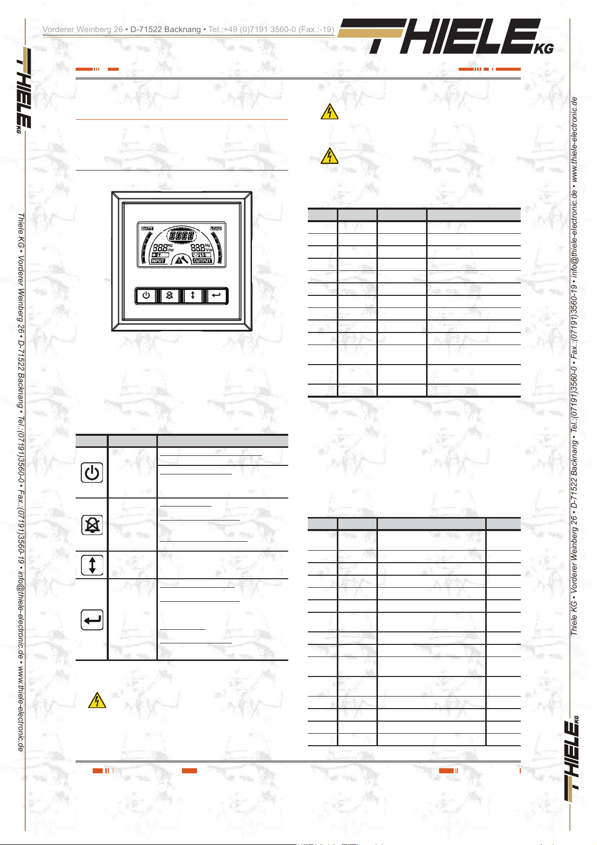
Vorderer Weinberg 26 • D-71522 Backnang • Tel.:+49 (0)7191 3560-0 (Fax.:-19)
6. Control panel.
6.1. Functionalities.
Thiele KG • Vorderer Weinberg 26 • D-71522 Backnang • Tel.:(07191)3560-0 • Fax.:(07191)3560-19 • [email protected] • www.thiele-electronic.de
The UPS has a graphic sc reen with LCD panel wit h four keys
and to colour backlight, blue and red. It is used the blue colour
as backlight with black text. When any critical alarm of the equipment is triggered, the ligh t changes to red (see table 8).
Fig. 12. Control panel view.
Ŗ The following critical alarms do not allow deactivating
the own acoustic alarm:
Low battery, Fan fault, internal Over temperature in the equipment and battery fault or damaged.
Ŗ
The acoustic alarm can be de activat ed when beeping,
but it will be activated ag ai n a s s o on as a new alarm
is triggered.
6.1.2. Acoustic alarms.
Code Condition Modulation Alarm silent function
BATT Warning Every 4 sec. It can be silenced
BTOP Warning Every 1 sec. It can be silenced
TEST Warning Every 2 sec. It can be silenced
OPVH Fault Continuous It can be silenced
OPVL Fault Continuous It can be silenced
OPST Fault Continuous It can be silenced
OVLD Warning Every 1 sec. It can be silenced
BAT H Warning Continuous It can be silenced
BATL Warning Every 1 sec. It can't be silenced
OVTP Warning Every 1 sec. It can't be silenced
OVTP Fault Continuous
FNLK Fault Continuous
BTWK Warning Continuous It can be silenced
It can't be silenced. It is silenced
when temperature decreases.
It can't be silenced. It is silences
whtn fan works.
6.1.1. Button functions.
Button Function Description
To start up or shutdown the equipment:
Start up and
shutdown
ON / OFF
UPS test.
acoustoc alarm
silencer
Selection
Enter
Tab la 6 . Functionality of the control panel keypad.
Ŗ Make sure that batteries are completely charged be-
fore doing any corresponding test.
Press the key for more than 3 sec..
To escape from fault mode:
Turn off the input protection from mains or
unplug the schucko plug from the wall outlet
and press this key for more than 2 seconds.
To do a battery test:
Hold this key pressed for more than 3 seconds.
To do the battery lifetime test:
Hold this key pressed for more than 10
seconds.
To deactivate the acoustic alarm:
Press this key for one seconde.
Press this key to select the setting value, one by
one.
Enter into the setting mode:
Hold this key pressed for more than 3 seconds.
Introducir la opción de ajuste:
Hold this key pressed for more than 1 second.
The equipment allows setting the blinking
parameters and the characters chain.
%QPſTOUGVVKPIU
Hold this key pressed for 1 second.
Escape from setting mode:
Hold this key pressed for 3 seconds or the key
ON/OFF for 0,5 seconds.
Tab la 7. Acoustic alarms. Condition and modulation.
6. 1 .3. UPS status and colour of the LCD
panel, depending on the condition.
By means of an abbrevia t ed chain of 3 to 4 charact ers (code), in
the LCD panel is displayed the status of the equipment.
The following tabl e 8 shows the corresponding d escription to
each letter sequence or chain.
Code Condition Description LCD colour
STBY Status UPS working on Standb y. Blue
IPVL Status Input voltage too low. Blue
IPVH Status Input voltage too high. Blue
IPFL Status Input frequency too low. Blue
IPFH Status Input frequency too high. Blue
NORM Status UPS working on line mode. Blue
AVR Status UPS working on stabilizer mode. Blue
BATT Warning UPS working on battery mode. Blue
BTOP Warning Battery disconnected. Red
TEST Warning
OPVH Fault
OPVL Fault Output voltage is t oo low. Red
OPST Fault Short-circuit at the output. Red
OVLD Warning Overload. Red
BAT H Warning Battery voltage is too high. Red
UPS working on battery in life / function
test.
Battery mode with output voltage too
high.
Blue
Red
Thiele KG • Vorderer Weinberg 26 • D-71522 Backnang • Tel.:(07191)3560-0 • Fax.:(07191)3560-19 • [email protected] • www.thiele-electronic.de
24
USER MANUAL
Page 25

Vorderer Weinberg 26 • D-71522 Backnang • Tel.:+49 (0)7191 3560-0 (Fax.:-19)
Thiele KG • Vorderer Weinberg 26 • D-71522 Backnang • Tel.:(07191)3560-0 • Fax.:(07191)3560-19 • [email protected] • www.thiele-electronic.de
6. 1 .4. Graphics displayed in the LCD
6.1.5. User settings.
By means of an abbreviated chain of 2 to 4 characters (code), the
configurable parameters are displayed in the LCD panel.
Table 10 shows the c orresponding des cription to each one of
these letters sequences or chain, as well as the possible selectable variables or values.
Code Condition Description LCD colour
BAT L Warning Battery voltage is too low. Red
OVTP Fault
FNLK Fault Fan is faulty or doesn't work. Red
BTWK Warning Battery faulty or damaged. Red
Tab la 8 . UPS status and LCD pa nel colour dep ending on the
Fault due to internal temperature too
high.
condition.
Red
panel.
Icon Description Function
Input voltage
and frequency.
Input plug
indicator.
Output voltage
and frequency.
Output plug
indicator.
UPS status
/ User setting
screen.
Warning
indicator.
Setting or
configuration.
Battery level
graph.
Load level graph.
Tabla 9. Button or control panel keypad funcionality.
It displays the voltage and frequency values of
the input.
The icon is displayed in the screen, if the mains
is inside the permissible range of the equipment.
It displays the voltage and frequency values of
the output.
The UPS has two outlets groups, > 1 kVA
models. the icon is displayed when their
respective outlets have voltage.
Acronym chain of the status mode. They diosplay
the condition of the equipment (see table 8).
Acronym chain of the values. They displayes the
options of the user setting ( see table10).
It is activated as warning fault mode or alarm in
the equipment.
It is activated when the equipment is on setting
or configuration mode .
It displayes the battery charge level in %, which is
equal to the available energy capacity.
The bar is divided into five parts, each part
corres ponds to a 20 % of t he total ca pacity o f
the battery set.
It displayes the load level connected at the output
of the equipment in %, equivalent to the power
consumed in real time.
The bar is divided into five parts, each part
corres ponds to a 20 % o f the load o r nomkna l
power of the equipment.
Code Description Values
OPV Output voltage selection.
AV Input voltage type
EBM External battery module
TEST Auto test.
AR Automatic restart.
GF
Green mode.
BZ Acoustic alarm control.
IEC outlets group 1
LS1
PQVCXCKNCDNGKPGSWKROGPVUŭM8#
IEC outlets group 2
LS2
PQVCXCKNCDNGKPGSWKROGPVUŭM8#
(220)=220V
(230)=230V
(240)=240V
(000)=No rm a l range
(001)=Wide range
(002)=Gen set
0 - 9 it is the quantity of
battery modules
(000) De a c t ive
(001) Active
(000) De a c t ive
(001) Active
(000) De a c t ive
(001) Active
(000) De a c t ive
(001) Active
(000) De a c t ive
(001) Active
(000) De a c t ive
(001) Active
Tab la 10. UPS status and character chain description.
6. 1 .6. Explanations about the user
settings and other ones.
6.1.6.1. Operating modes.
Ŗ Normal range: In this mode, the input voltage range are ±20%.
Ŗ Wide range: In this mode, the input voltage range are from
+20% to –30%.
Ŗ Gen mode: On this mod e the load is transfer red to battery
mode (inverter output), when frequency is higher than the
upper and lower threshold , of 40 and 80 Hz respectively.
Ŗ Battery m ode (inverter output): When the UPS is working
out from the range or dur ing a blackout , the acous tic alarm
beeps every four sec on ds. A lso t he LCD panel d isp lays the
"BATT" indication, corresponding to the status of the equipment to show the UPS operating mode -Battery mode-.
If on this condition, the battery capacity is low, the alarm
beeps once per second and the LCD panel displays the
"BA TL" indication.
Ŗ Standby mode.
When the UPS is shutdown and it remains connected to the
wall outlet, it will be on standby mode. In the LCD panel will
display "STB Y" t o sho w tha t th e po w e r supply t o the loa ds is
not available. On this mode the battery will be charged, if it
was needed.
6.1 .6.2. IEC outlet groups.
Ŗ It is possible to set the status (active or deactive) of the both
available connector groups LS1 and LS2, at any time and
separately .
6JKUHWPEVKQPKUPQVCXCKNCDNGKPGSWKROGPVUŭM8#
because there is only one IE C connector group .
Ŗ To set the IEC outlet group through the LCD panel of th e
equipment, proceed as follows:
1.- Enter into the configuration mode.
Press the key
will shift to setting mode.
for more than 3 seconds and the UPS
Thiele KG • Vorderer Weinberg 26 • D-71522 Backnang • Tel.:(07191)3560-0 • Fax.:(07191)3560-19 • [email protected] • www.thiele-electronic.de
SALICRU
25
Page 26

Vorderer Weinberg 26 • D-71522 Backnang • Tel.:+49 (0)7191 3560-0 (Fax.:-19)
Thiele KG • Vorderer Weinberg 26 • D-71522 Backnang • Tel.:(07191)3560-0 • Fax.:(07191)3560-19 • [email protected] • www.thiele-electronic.de
6.1 .6.3. Setting the UPS to connect it with "n"
Ŗ In order to be sure that the LCD panel displays the correct
Ŗ Proceed as follows:
2.- Select the configuration elements.
Press the key
stated in table 10 and go forward or backward till reaching
"LS1 " or "L S2" as i t is r equir ed.
3.- Validate the configuration element.
When the LCD panel disp lays "LS1" or "LS2", press the
for more than one second to enter into the ele-
key
ment to set. The values of the variables blink (blinking
mode).
4.- Select the configuration value.
Press the key
lect the value (001) or (000) to set the desired IEC outlet
group, as turned on or off respectively.
5.- Confirm the configuration.
Press the key
the previous point 2.
6.- Escape from setting mode.
Press the key
seconds, to escape from the setting mode.
to select the configurable elements
to select the configuration value. Se-
for one second, th e UPS will return to
for 3 seconds or the key for 0,5
battery modules.
remaining capacity of the batteries, the available quantity of
battery modules has to be set and updated when facing any
modification, otherwise the displayed data will not be real.
/QFGNUŭM8#FQPQVJCXGEQ PPGEVQT UVQGZ VGPFV JG
back up time.
1.- Enter into the configuration mode.
Press the key
will shift to setting mode.
2.- Select the configuration elements.
Press the key
stated in table 10 and go forward or backward till reaching
"EBM".
3.- Validate the configuration element.
When the LCD panel disp lays "EBM", press the key
for more than one second to enter into the element t o set.
4.- Select the configuration value.
Press the key
ules available for the UPS.
5.- Confirm the configuration.
Press the key
the previous point 2.
6.- Escape from setting mode.
Press the key
seconds, to escape from the setting mode.
for more than 3 second s an d t he UPS
to select the configurable elements
to select the quantity of battery mod-
for one second, th e UPS will return to
for 3 seconds or the key for 0,5
3.- Validate the configuration element.
When the LCD panel displays "GF" , press the key
more than one second to enter into the element to se t.
4.- Select the configuration value.
Press the key
Select the value (001) to activate function.
5.- Confirm the configuration.
Press the key
the previous point 2.
6.- Escape from setting mode.
Press the key
seconds, to escape from the setting mode.
to select t he con fig ur at ion v a lue.
for one second, th e UPS will return to
for 3 seconds or the key for 0,5
for
6. 1 .6.4. Setting the "Gree n " fun cti on.
Ŗ If this function is activated, the UPS disable the output when
it is on battery mode when it is not detected a minimum of
consumption. By default, this feature is deactivated, if it is
needed to modify it, proceed as follows :
1.- Enter into the configuration mode.
Press the key
will shift to setting mode.
2.- Select the configuration elements.
Press the key
in table 10 and go forward or backward till reaching "GF".
26
for more than 3 second s an d t he UPS
to select the configurable elements stated
Thiele KG • Vorderer Weinberg 26 • D-71522 Backnang • Tel.:(07191)3560-0 • Fax.:(07191)3560-19 • [email protected] • www.thiele-electronic.de
USER MANUAL
Page 27

Vorderer Weinberg 26 • D-71522 Backnang • Tel.:+49 (0)7191 3560-0 (Fax.:-19)
7. Maintenance, warranty
7. 1 . Maintenance of the battery .
Thiele KG • Vorderer Weinberg 26 • D-71522 Backnang • Tel.:(07191)3560-0 • Fax.:(07191)3560-19 • [email protected] • www.thiele-electronic.de
Ŗ Pay attention to the saf ety instructions regarding battery and
Ŗ The equipment from SPS.ADV ANCE RT series only requires
Ŗ The UPS has to be charge d once, ever y 4 or 6 months if i t
Ŗ In hot areas, battery has to be charged every 2 months. The
Ŗ Under normal conditions, the battery lifetime is from 3 to 5
Ŗ Always replace them with the same quantity and type.
Ŗ Do not replace one battery only. All batteries have to be re-
Ŗ Usually, the batteries should be char ged and discharged
7 .1. 1. Notes for installing and replacing
Ŗ If it is needed to replace the connection of any wire, purchase
and service.
the stated in section 1 .2.3.3
a minimum maintenanc e. The used bat tery in the s tandard
models is lead acid , sealed, VRLA and maintenanc e free.
These models require a minimum of reparations. The only requirement is to charge the UPS regularly, in order to prolong
the battery lifetime. Meanwhile, it is connected to the power
supply, never mind if the UPS is ON or OFF, it will keep the
batteries charged.
has not been used for long time .
charging time has to be 12 hours as minimum.
years 25º C. In case that the battery was not in good c o nd i tions, it has to be replaced before. This replacement has to
be done by qualified staff.
placed at the same tim e and followi ng the instructi o ns of the
manufacturer.
every 4 or 6 months. The charging would be started after a
UPS shutdown due to a low battery (discharging ). Charging
time for standard UPS should be 1 2 hours as minimum.
the batteries.
original parts through authorised distributors or service cen-
tres in order to avoid overheating or sparks with risk of fire
because the size could not be enough .
Ŗ Do not short the + and - poles of the batteries, there is risk of
fire or electrocution.
Ŗ Be sure that there is no voltage bef ore touching the batteries.
Battery circuit is not isolated f rom the input circuit. Hazardous
voltages can be fo und b et wee n th e bat tery and earth termi nals.
Ŗ Even with the input circuit breaker switch from protection
panel is turned off, the internal parts of the UPS are still connected to the batteries, so there are hazardous voltages inside.
Therefore, before doing any reparation or maintenance task,
the internal battery fuses and/or the interlink connections between them and the UPS, have to be removed.
Ŗ Batteries have hazardous voltages. The battery main-
tenance and replacement have to be done by qualified
personnel and familiarised with them. Nobody else can manipulate them.
7.2. UPS T rouble Shooting guide.
If the UPS doesn't work pro perly, check the infor matio n given
by the LCD of the control pan el, acc ord ing to the m ode ls and
power of the equipment . Tr y to solve the problem by me ans
of the established steps in the tables 11 and 12. In case the
problem persists, consult with our Service and Technical Support S.T.S..
When it is needed to contact with our Service and T echnical Support S.T .S. , provide the following information:
Ŗ UPS model and serial number .
Ŗ Date when the problem occurred.
Ŗ Complete description of the problem, including the informa-
tion given by the LCD panel and the status of the alarms.
Ŗ Power supply condition, type of load and the lev el connected
to the UPS, ambient temperature , cooling conditions.
Ŗ Information of the batteries (capacity and battery quantity), if
the equipment is (B0) or (B 1) -with external batteries-.
Ŗ Other informations that yo u may think tha t they are important.
7 .2. 1. FAQ. Acoustic alarms.
Acoustic alarm Possible cause Solution
Beep every 4 seconds. The equipment is on battery mode
Beep every second with LCD from control
panel with "BATL" indication.
Beep every second with LCD from control
panel with "OVLD" indication.
LCD panel is still on red colour UPS fault. Consult with the S.T.S..
SALICRU
Low battery voltage. Save the taks in process and shutdown the load/s and the UPS.
Overload at th e outp ut.
Check the input voltage and/or the po we r cord is connected to the A C
wall outlet.
Check the load level connected at the output and proceed to remove
the exceeded one, keeping in mind the critical loads.
Tab la 11. Acoustic alarms.
Thiele KG • Vorderer Weinberg 26 • D-71522 Backnang • Tel.:(07191)3560-0 • Fax.:(07191)3560-19 • [email protected] • www.thiele-electronic.de
27
Page 28
Vorderer Weinberg 26 • D-71522 Backnang • Tel.:+49 (0)7191 3560-0 (Fax.:-19)
7.2.2. FAQ. Ge n er a l i n d icati o n s .
Problem Possible cause Solution
The equipment doesn't start up when pressing
Thiele KG • Vorderer Weinberg 26 • D-71522 Backnang • Tel.:(07191)3560-0 • Fax.:(07191)3560-19 • [email protected] • www.thiele-electronic.de
Tab la 12 . Troubleshooting guide. Warning indicat ions.
over the corresponding ke y.
The equipment is ON but the loads do not
have power supply
Back up time is too short.
Continuous alarm and LCD in red colour. Equipment fault Consult with the S.T .S..
Buttons or keys are not operative.
Internal f us e blo w n . Consult with the S.T.S..
Jumpers at the output are no t connected
properly.
There is no voltage in the outlets.
Battery is low or the load le vel is v ery low. Recharge the battery for 24 hours as minimum.
Battery is depleted or damaged Consult with the S.T.S. to replace it.
Setting mode is not the suitable. Checl the setting procedure.
Buttons or keys are faulty. Consult with the S.T .S..
Connect the output jumpers.
Check LS1 and LS2 (not available in models up to 1 kVA), are selected
from "001" to "000".
7.3. Warranty conditions.
The limited warranty only applies to those products that you acquire for commercial or industrial use in the normal development
of your business .
7.3.1. Covered product.
SPS.ADVANCE RT.
7.3.2. Warranty terms.
This product is guaranteed against any parts and/or labour defect for 12 months period from its commissioning by our company staff or other specifically authorised, or 18 months from its
factory deliver y, whichever expires first. In c ase of failure of t he
product inside the warranty period, we must repair, at our facilities at no cost, the faulty part or parts. The transport expenses
and packaging will be borne to the user.
We guarantees for period time higher than 10 years, the availability of parts and spare parts, as hardware as software, as
well as a complete assistance regarding the reparations, components replacement and software updating.
7 .3.3. Out of scope of supply .
Our company is not forced by the warranty if it appreciates
that the defect in the product doesn’t exist or it was caused by
a wrong use, negligence, installation and/or inadequate testing,
tentative of repairing or not authorized modification, or any other
cause beyond the foreseen use, or by accident, fire , lightnings or
other dangers. Neither it will cover, in any case, compensations
for damages or injuries.
7.4. Description of the available
maintenance and service
contracts.
When the warranty is expired, and adapting to the customer’s
needs, has several maintenance modalities:
Preventive.
It guarantees a higher safety to preserve the correct operating of
the equipment s with a yearly pr eventive visit , in whic h the spe cialised technicians of our company make several tests and sets
in the systems:
Ŗ Measurement and write down input currents and voltages
among the phases.
Ŗ Measurement and write down output currents and voltages
among the phases.
Ŗ Measurement and write down floating currents and voltages
, discharging and charging batteries.
Ŗ Checking the logged alarms.
Ŗ Checking and test ing the measurem ents of the digit al LCD
panel:
Input voltages
Input currents
Output voltages
Output currents
Temperatures
Battery voltage and currents.
Ŗ Check the battery status.
Ŗ Check the fan status.
Ŗ Bypass test.
Ŗ Make a general cleaning of the equipment.
Ŗ Controlling the mechanical parts and temperatures.
This way, it is guaranteed the perfect operating and the possible
coming fa ul ts a r e avoided.
These supervisions are usually done without shutdown the
equipment. In those cases that a shutdown were needed, date
and time would agree with the customer to do the task.
This maintenance modality covers, inside the working timetable,
all the journey expenses and manpower.
Corrective.
When a fault occur s in the equipment o perating, and previous
notice to our Ser vic e and Technical Su pport (S.T.S.), in which a
specialized technician will establish the failure scope and he will
determine a first diagnostic, the corrective action starts.
Thiele KG • Vorderer Weinberg 26 • D-71522 Backnang • Tel.:(07191)3560-0 • Fax.:(07191)3560-19 • [email protected] • www.thiele-electronic.de
28
USER MANUAL
Page 29
Vorderer Weinberg 26 • D-71522 Backnang • Tel.:+49 (0)7191 3560-0 (Fax.:-19)
The needed visits for its correct resolution are unlimited and they
are included inside the maintenance modalities. It means that in
case of failure, we will check the equipments as many time as it
were needed.
Both preventive and corrective maintenance contracts, is possible to determine the intervention timetable and response times,
as well as exclusion or inclusion parts in partial or total way, with
the purpose to be adapted to the customer’s need.
Consult our Website to have more information
Thiele KG • Vorderer Weinberg 26 • D-71522 Backnang • Tel.:(07191)3560-0 • Fax.:(07191)3560-19 • [email protected] • www.thiele-electronic.de
7.5. T ech nical service network.
Coverage, both national and international, from our Service and
Technical Support (S.T.S.), can be found in our Website.
SALICRU
Thiele KG • Vorderer Weinberg 26 • D-71522 Backnang • Tel.:(07191)3560-0 • Fax.:(07191)3560-19 • [email protected] • www.thiele-electronic.de
29
Page 30
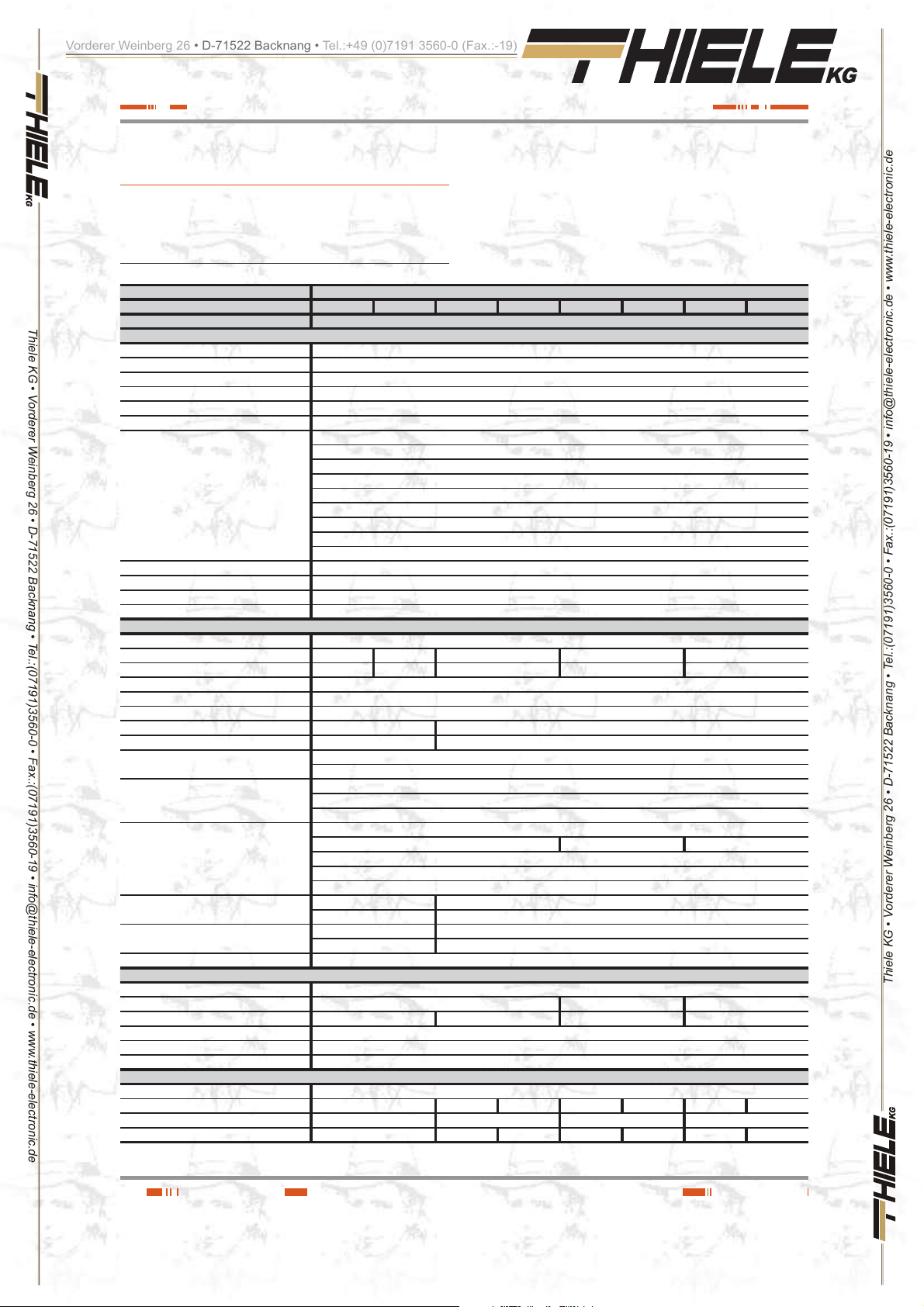
Vorderer Weinberg 26 • D-71522 Backnang • Tel.:+49 (0)7191 3560-0 (Fax.:-19)
8. Annexes.
8.1 . Main general specifications.
Models: SPS.ADV RT
Available powers (kVA / kW) 0.750 / 0.675 1 / 0.9 1.5 / 1.35 1.5 / 1.35 (B1) 2 / 1.8 2 / 1.8 (B1) 3 / 2.7 3 / 2.7 (B1)
Thiele KG • Vorderer Weinberg 26 • D-71522 Backnang • Tel.:(07191)3560-0 • Fax.:(07191)3560-19 • [email protected] • www.thiele-electronic.de
Technology Line interactive with sinewave output
Input
Permissible power factor of the laods 0.9
Cold start (from batteries) Yes, by default with 50 Hz frequency
Input topology Single phase
Quantity of wires 3 wires - Phase R(L) + Neutral (N) and earth
Voltage 220 / 230 / 240 V AC
Voltage range 176 ÷ 288 V AC
Transfer voltage:
- To battery due to low voltage mains 176 / 184 / 192 V AC (±4 %) -Normal-; 154 / 161 / 168 V AC (±4 %) -Wide ranges-
- Return from battery due to voltage restored 186 / 194 / 202 V AC (±4 %) -Normal-; 164 / 1 71 / 178 V AC (±4 %) -Wide ranges-
- Limit voltage Boost 198 / 207 / 216 V AC (±4 %)
- Return voltage Boost 206 / 215 / 255 V AC (±4 %)
- Limit voltage Buck 233 / 243 / 254 V AC (±4 %)
- Return voltage Buck 225 / 236 / 246 V AC (±4 %)
- To battery due to high voltage mains 264 / 276 / 288 V AC (±4 %)
- Return from battery due to voltage restored 254 / 266 / 278 V AC (±4 %)
Protection range against overvoltages L-N: 320V 460 Joules / 6500 A
Input frequency range - Normal (45 - 55 / 55 - 65 Hz) (±0,1 Hz ); Autosensing
Input frequency range - Genset mode 40 - 70 Hz
Generator set Yes
Output
Power factor 0.9
Power (kVA) 0.750 1 1.5 2 3
Power (kVW) 0.675 0.900 1.350 1.8 2.7
Wave shape Pure sinewave
Nominal voltage 220 / 230 / 2 40 V A C , selectable
Voltage accuracy ( ba ttery mode) ± 5 %
Voltage THD linear load < 10 % < 3 %
Voltage THD non-linear load < 12 % < 6 %
Frequency
Transfer time
Line mode to battery mode (normal mode) 2 - 6 ms.
Line mode to battery mode ( Genset mode ) 13 ms as maximum
Efficiency at full load:
Line mode with charged battery 98 % 96 % 98 %
Buck mode with charged ba tte ry > 95 %
Boost mode with charged battery > 92 %
Battery mode 82 %
Overload on line mode
Overload on battery mode
Crest factor 3:1
Batteries (AGM sealed 3 - 5 years lifetime)
Voltage 12 V DC
Capacity 9 Ah 7 Ah 9 Ah
Quantity of batteries in serial / voltage string 2 / 24V DC 3 / 36 V DC 6 / 72 V DC 6 / 72 V DC
Low battery voltage, block 11.4 V DC
Low battery voltage 10.8 V DC block
End voltage blocking 9.6 V DC block
Internal battery charger
Floating voltage per block 13.6 - 13.8 V DC
Maximum charging current 1.1 A 1.5 A - 1.5 A - 1.5 A Recharging time (charger 1.1 or 1.5 A) 8 hours at 90% 4 hours at 90% 3 hours at 90% 4 hours at 90%
Optional charger - - 7 A - 7 A - 7 A
110 % ± 10 % : 3 min. 11 0 - 118 % : 3 min.
150 % ± 10 % : 0,2 sec. 119 - 160% : 0,2 sec.
ŮvUGE ŮvUGE
ŮvUGE ŮvUGE
With mains present, synchronised to nominal of the input (45-55 / 55-65 Hz)
Free running (battery mode) 50 / 60 ±0.1 Hz
Thiele KG • Vorderer Weinberg 26 • D-71522 Backnang • Tel.:(07191)3560-0 • Fax.:(07191)3560-19 • [email protected] • www.thiele-electronic.de
30
USER MANUAL
Page 31
Vorderer Weinberg 26 • D-71522 Backnang • Tel.:+49 (0)7191 3560-0 (Fax.:-19)
Models: SPS.ADV RT
Available powers (kVA / kW) 0.750 / 0.675 1 / 0.9 1.5 / 1.35 1.5 / 1.35 (B1) 2 / 1.8 2 / 1.8 (B1) 3 / 2.7 3 / 2.7 (B1)
Generals
Cold start Yes
Green mode Yes (selectable)
IEC inlet connectors 10 A 16 A
IEC outlet connectors 4 x IEC 10A 8 x IEC 10A (4 x LS1 + 4 x LS2) + 1 IEC 1 6 A (3kV A UPS only)
Communication ports 2 (RS232 -DB9- and USB, m utually exclusive)
Dry contacts Yes, through optocouplers (low battery and mains fault). Included in the same connector as the RS232 port.
Protecti on co nnec tors f or Mod em / ADSL
/ Fax
Thiele KG • Vorderer Weinberg 26 • D-71522 Backnang • Tel.:(07191)3560-0 • Fax.:(07191)3560-19 • [email protected] • www.thiele-electronic.de
Installation connector for external EPO No Yes
Slot for COM option cards No Yes
Option cards (to insert into the slot) No AS400, SNMP, remote management internet or intranet
Monitoring software WinPower (free download )
Ruido acústico a 1 m en modo línea < 40 dB < 45 dB
Acoustic noise at 1 m on battery mode < 45 dB < 50 dB
Operating temperature 0.. +40 ºC
Storage temperature –15.. +50 ºC
Storage temperature with no batteries –20.. +70 ºC
Operating altitude ŭO%
Relative humidity 0-95 % non-condensing
Protection degree IP20
UPS dimensions -Depth x Width x Height-
(mm)
Bat. dimensions -Depth x Width x Height- (mm) - 436 x 438 x 86.5 (2U) 608 x 438 x 86.5 (2U)
UPS weight (k g) 13 14 18.5 12.5 28 15 29 17
Battery modules weight (kg) - 20.5 33.5
Safety EN-IEC 62040-1; EN-IEC 60950-1
Electromagnetic compatibility (EMC) EN-IEC 62040-2
Marking CE
Quality system ISO 9001 and ISO 140001
436 x 438 x 86.5 (2U) 608 x 438 x 86.5 (2U)
1 input / 1 output
1501 - 3000 m (0.. +35 ºC)
Tab la 13 . General technical specifications.
8.2. Glossary.
Ŗ AC.- It is nominated as alternating current (abbrevia-
tion in Spanish CA and in English AC) to the electr ical
current in which the magnitude and direction varies
in a cyclic way. The most commo n wave shape of the
alternating current is sinewave, because the energy
transmission is better . Nev ertheless, some applications
could need other period wave shapes, like triangular or
square.
Ŗ Bypass.- Manual or automatic , it is the ph ys ical j unction be-
tween the input and the output electric device.
Ŗ DC.- The direct current (CC in Spanish, DC in English) is the
continuous electron flow through a cable between two points
with different potential. Unlike the alte rnating current, in direct
current the electrical loads always flow in the same direction
from the highest potential point to the lowest one. Although,
usually the direct current is identified with the constant current (for example the one supplied by t he batter y), it is continuous any current that alway s maintain the pola rity .
Ŗ DSP .- It is the acronym of Digital Signal Processor. A DSP is
a system based on a proc essor or micr oproces sor that has
instructions in it, a hardware and an optimised software to
develop applications where nume rical operations a re needed
with very fast speed. Due to this, it is very useful to process
analogical signals in real time: in a system that runs in this
way (real time) samples are received, usually coming from an
analogical/digital converter(ADC ) .
Ŗ Power factor.- It is defined as power factor, p.f., of an alter-
nating current circuit, as the ratio between the active power,
P, and the apparent power, S, or as the cosines of the angle
that make the current and voltage vectors, designating as
EQUDGKPIVJGXCNWGQHVJCVCPING
Ŗ GND.- The term ground, as its name states, refers to the po-
tential of the earth surface.
Ŗ EMI filter.- Filter able to decrease the electromagnetic inter-
ferences, which is the perturbation that happens in a radio
receptor or in any other electrical circuit caused by the electromagnetic radiation coming from an external source. Also
it is known as EMI, E lectroMagnetic In te rference, Ra dio Frequency Interference or RFI. This perturbation can derate or
limit the efficiency of the circuit.
Ŗ IGBT.- The Insulated Gate Bipolar Transistor is a semicon-
ductor device that is used as a controlled switch in power
electronic circuits. This device has the feature of the gate
signal of the effe ct fiel d transi stors wi th the c apaci ty of hi gh
current and low volt age saturation of the bip olar transistor,
combining an isolated FET gate for the input and a bipolar
transistor as switch in a single device. The triggering circuit
of the IGBT is as the MOSFET one, while the driving features
are like the BJT.
Ŗ Interface.- In electronic, telecommunications and hardw are ,
an interface (electro nic) is the por t (physic al circ uit) through
which are sent or received signals from a system or subsystems toward others.
Ŗ kVA.- The voltampere is the un it of the apparent power in
electrical current. In direct current is almost equal to the real
power but in alternating current can defer depending on the
power factor.
Thiele KG • Vorderer Weinberg 26 • D-71522 Backnang • Tel.:(07191)3560-0 • Fax.:(07191)3560-19 • [email protected] • www.thiele-electronic.de
SALICRU
31
Page 32

Vorderer Weinberg 26 • D-71522 Backnang • Tel.:+49 (0)7191 3560-0 (Fax.:-19)
Ŗ LCD.- LCD acronym of Liquid Crystal Display, device in-
vented by Jack Janning, who w as employee of NCR. It is an
electric system of data presentation based on 2 transparent
conductor layers and in the middle a special crystal liquid that
have the capacity to orientate the light when trespassing.
Ŗ LED.- LED acronym of Light Emitting Diode, is a semicon-
ductor device (diode) that emits light almost monochrome
with a very narrow spectrum, it means, when it is direct polar ized and it is crossed by an electric current. The colour , (wa ve
longitude), depends on the semiconductor material used in
Thiele KG • Vorderer Weinberg 26 • D-71522 Backnang • Tel.:(07191)3560-0 • Fax.:(07191)3560-19 • [email protected] • www.thiele-electronic.de
its construction, being able to vary from the ultraviolet one,
going through t he visible s pectrum li ght, to the infrare d, receiving these last ones the denomination of IRED (Infra Red
Emitting Diode).
Ŗ Circuit breaker.- A circuit breaker or switch, is a device
ready to break the electrical current of a circuit when it overcomes the maximum set values.
Ŗ On-Line mode.- Regarding to an equipment, it is on line
when it is connected to the system, and it is in operation, and
usually has its power supply turned on.
Ŗ Inverter .- An inver ter, is a circuit use d to conver t dire ct cur-
rent into alternating current. The function of an inverter is to
change an input voltage of direct current into a symmetrical
output voltage of alternating current, with the requi red magnitude and frequency by the user or the designer.
Ŗ Rectifier.- In electronic, a rectifier is the element or circuit
that allows to convert the alternating current into direct current. This is done by rectifier diodes, which can be solid state
semiconductors, vacuum or gassy valves as the mercury
vapour. Depending on the features of the alternating current
power supply used, it is classified as single phase, when the y
are fed by a single phas e electrical m ains, or three phase
when they are fed by the three phases. Depending on the
rectification type, they can be half wa ve, when only one of the
current semi-cycles is used, or full wave, where both semicycles are used.
Ŗ Relay.- The relay(in French relais, relief) is an electrome-
chanical device that works as a switch controlled by an electric circuit where, through an electromagnet, a set of contacts
are moved and it allows to open or to close other independent
electric circuits.
Ŗ SCR.- Abbreviation of «Silicon Controlled Rectifier», called
commonly as Th y ri st o r: s em icon duct o r device of 4 lay e r th a t
works as almost an ideal switch.
Ŗ THD.- They are the acronyms of «Total Harmonic Distor-
tion». The total harmonic distortion is done when the output
signal of a system is not equivalent to the one that enter into
it. This lack of linearity affects to the wave shape, because
the equipment has introduced harmonics that they were not
in the input signal. As they are harmonics, it means multiple
of the input signal, this distortion is not so dissonant and it is
more difficult to detect.
32
Thiele KG • Vorderer Weinberg 26 • D-71522 Backnang • Tel.:(07191)3560-0 • Fax.:(07191)3560-19 • [email protected] • www.thiele-electronic.de
USER MANUAL
 Loading...