

80.0 in / 2030 mm
lage Length
Warning !This model is not a toy.
It is designed for maximum performance. Please seek advice if one is not familiar with this kind
of engine powered precision model. Operating this model without prior preparation may cause
injuries. Remember, safety is the most important thing. Always keep this instruction manual at
hand for quick reference.
* Specific ations are sub ject to change with out notice.*
15.5-17 lbs / 7100-7700 g
Wing Span 80.0 in / 2030 mm
Wing Area
Flying Weight
Fuselage Length
15.5-17 Ibs / 7100- 7700 g
1138 sq in / 73.4 sq dm
68 in / 1730 mm
Specifications
E
A
D
R
-
Y
T
-
T
S
O
O
-
F
M
L
L
Y
A
ARF
-160
Requires: 6- channel radio w/ 7 standard servos
and 2 low profile retract servos
1.60 cubic inch displacement 2- stroke(glow)
INSTRUCTION MANUAL
FACTORY PRE-FABRICATED
ALMOST-READY-TO-FLY (ARF) SERIES
MADE IN CHINA
(
)
A122
P. 3 - 11
INDE X
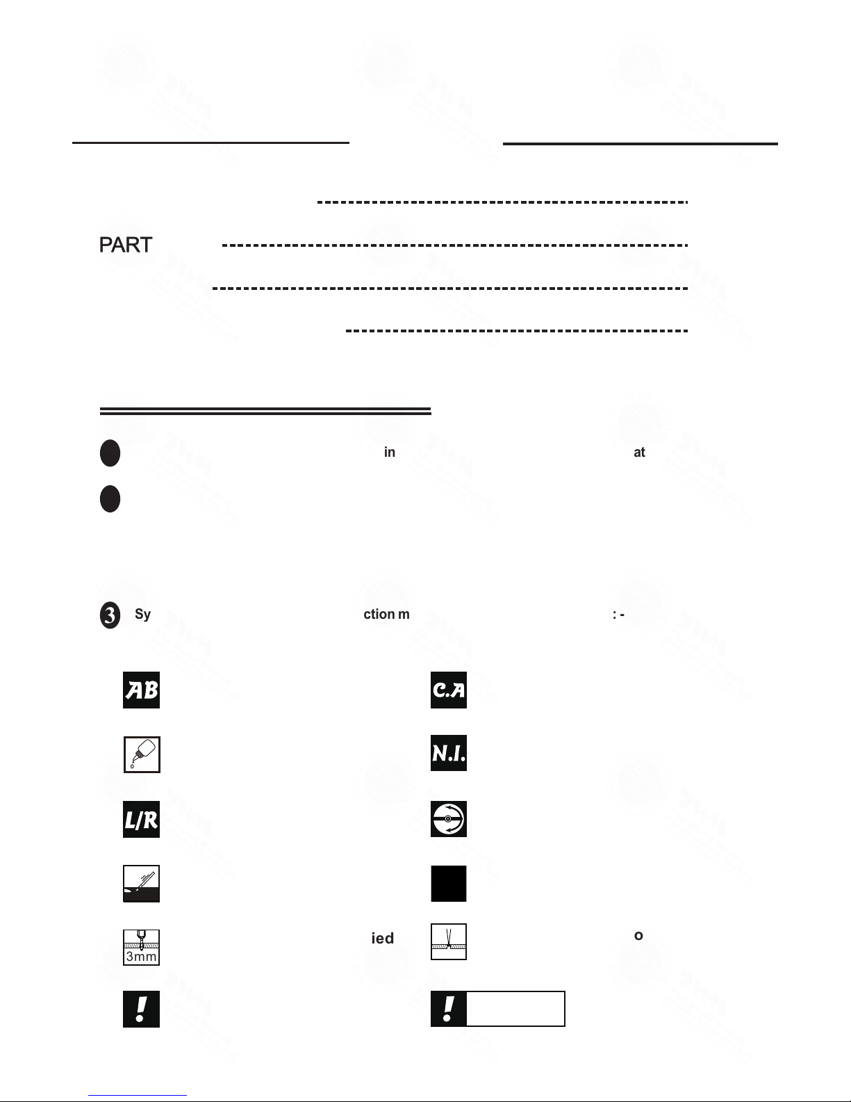
BEFORE YOU BEGIN
PARTS LIST
ASSEMBLY
SAFETY PRECAUTIONS
P. 1
P. 2
P. 11
BEFORE YOU BEGIN
Read through the manual before you begin, so you will have an overall idea of what to do.
Symbols used throughout this instruction manual comprise of the following : -
1
2
3
P.1
Check all parts. If you find any defective or missing parts contact your local dealer. Please DRY FIT
and check for defects for all parts that will require CA or Epoxy for final assembly. Any parts you
find to be defective after the gluing process may be difficult to remove for warranty replacement. The
manufacturer will replace any defective parts. but will
not
extend to the parts that are good before
gluing to defective parts during assembly. Warranty will not cover any parts modified by customer.
-160
3mm
Do not overlook this symbol!
Cut off shaded portion.
Peel off shaded portion
covering film.
Pay close attention here!
Pierce the shaded portion
covering film.
Must be purchased separately!
Drill holes with the specified
diameter (here: 3mm).
Ensure smooth non-binding
movement while assembling.
Apply instant glue
(C.A.glue, super glue.)
Assemble left and right
sides the same way.
Apply epoxy glue.
Apply thread locker
Warning!
A122PO31681704

Parts List
COVE RIN G:
TOUGHLON STL 203 LIGHT GRAY
TOUGHLON STL 331 CUB YELLOW
TOUGHLON STL 340 OLIVE DRAB
P.2
1. MAIN WING -- 1 pair
2. SCREW PWA2x8mm -- 16 pcs
SCREW PB2x22mm -- 4 pcs
SCREW PB2x20mm -- 2 pcs
SCREW PB2x25mm -- 4 pcs
SCREW PB2x22mm -- 2 pcs
CLEVIS -- 4 pcs
STRAPER -- 4 pcs
FUEL TUBE Ø6x5mm -- 8 pcs
TRI-HORN M3x14mm(For Aileron & Flap)(L) -- 4 sets
PUSHROD Ø1.8x137mm w/ Threads(For Aileron Servos -- 2 pcs
PUSHROD Ø1.8x115mm w/ Threads(For Flap Servos -- 2 pcs
SERVO MOUNTING PANEL 22x68x78mm -- 4 pcs
3. RETRACTABLE LANDING GEAR -- 1 set
RETRACTABLE LANDING GEAR COVER -- 1 set
SCREW PM2x8mm -- 12 pcs
WASHER d2xD5mm -- 24 pcs
M2 NUT -- 12 pcs
COVERING FILM 45x80mm -- 2 pcs
PLYWOOD 3x261x60mm -- 1 pc.
4. FUSELAGE -- 1 pc.
SCREW PA3x15mm -- 1 pc.
WASHER d3.2xD12mm -- 1 pc.
5. ENGINE MOUNT PL5911120 -- 1 set
SOCKET HEAD SCREW M6x30mm -- 4 pcs
WASHER d6xD15mm -- 4 pcs
BLIND NUT M6xD18mm -- 4 pcs
6. FUEL TANK 800cc -- 1 set
DOUBLE-SIDED TAPE 40x160mm -- 1 pc.
CABLE TIE 1.5x8x500mm -- 1 pc.
PLYWOOD 6x61x133(For Throttle Servo) -- 1 pc.
BALSA 6x6x41mm(For Throttle Servo Stand) -- 2 pcs
7. STABILIZER & ELEVATOR -- 1 set
SCREW PA3x12mm -- 2 pcs
WASHER d3xD7mm -- 2 pcs
STABILIZER TUBE Ø9.5x458mm -- 1 pc.
8. TAIL LANDING GRAR -- 1 set
TAIL WHEEL Ø30mm -- 1 pc.
COLLAR Ø2.6mm w/ set screw -- 1 set
SCREW PA3x12mm -- 2 pcs
9. VERTICAL FIN & RUDDER -- 1 set
10. SCREW PB2x30mm -- 3 pcs
FUEL TUBE Ø6x5mm -- 1 pc.
CLEVIS -- 1 pc.
PUSHROD Ø1.8x970mm w/ Threads(For Rudder) -- 1 pc.
TRI-HRON M3x14mm(L)(w/ o-Basa For Rudder) -- 1 set
11.SCREW PB2x20mm -- 4 pcs
SCREW PB2x18mm -- 2 pcs
FUEL TUBE Ø6x5mm -- 2 pcs
CLEVIS -- 2 pcs
TRI-HORN M3x14mm(L)(For Elevator) -- 2 sets
PUSHROD Ø1.8x745mmw/ Threads(For Elevator) -- 2 pcs
12. LINKAGE CONNECTOR Ø2.1mm -- 1 set
13. PLYWOOD 6x61x133mm(For Elevator\ Rudder) -- 2 pcs
BALSA 6x6x41mm(For Elevator\ Rudder Servo Stand) -- 4 pcs
PUSHROD CONNECTOR PL4410010 -- 1 set
FUEL TUBE Ø6x5mm -- 2 pcs
STRAPER PL4112102 -- 2 pcs
PUSHROD Ø1.8x120mm (For Elevator) -- 1 pc.
SPONGE 10x80x200mm(For Radio Equipment) -- 2 pcs
14. ANTI-VIBRATION MOUNT 4C-120 -- 1 set
INCLUDE:SOCKET HEAD SCREW M4x35mm -- 4 pcs
SCREW KM3x20mm -- 8 pcs
WASHER d4xD12mm -- 8 pcs
M3 NYLON INSERT LOCK NUT -- 8 pcs
M4 NYLON INSERT LOCK NUT -- 4 pcs
COPPER TUBE d3.1xD4x9.1mm – 4 pcs
COPPER TUBE d4.1xD5x9.4mm – 4 pcs
COPPER TUBE d3.1xD5x9.1mm – 4 pcs
IRON PLATE 2x12x75mm(For Engine Mount) -- 1 pc.
THROTTLE PUSHWIRE Ø1.2x360mm -- 1 pc.
PLASTIC TUBE d2xD3x110mm -- 1 pc.
15. COWLING -- 1 pc.
TRANSPARENT 3D TEMPLATE -- 1 pc.
TRANSPARENT 3D TEMPLATE 0.5mmPVC -- 1 pc.
SCREW PM3x10mm -- 4 pcs
SILICON GROMMET d2.5xD8.5mm -- 4 pcs
M3 NYLON INSERT LOCK NUT -- 4 pcs
WASHER d3xD7mm -- 8 pcs
SCREW PA3x12mm -- 4 pcs
PLASTIC SPINNER(w/ alu .back plate)Ø89mm -- 1 set
ALUMINUM PLATE 1.5x12x220mm -- 2 pcs
16. SCREW PM3x70mm -- 2 pcs
WASHER d3xD7mm -- 8 pcs
SCREW HM4x45mm -- 2 pcs
WASHER d4xD15mm -- 2 pcs
SOCKET HEAD SCREW M3x18mm -- 2 pcs
M3 NYLON INSERT LOCK NUT -- 2 pcs
M3 NUT -- 2 pcs
SCREW PWA3x12mm -- 3 pcs
WING TUBE Ø25.4x750mm -- 1 pc.
WING TUBE Ø9.5x382mm -- 1 pc.
WING PROTECTION -- 1 pc.
ALUMINUM PLATE 2.3mm(For Wing) -- 4 pcs
AIR SCOOP -- 1 pc.
17. CANOPY -- 1 pc.
SCREW PWA2.3x8mm -- 8 pcs
SILICON GROMMET d1.5xD6.5mm -- 8 pcs
DOUBLE SIDED TAPE 8x1230mm -- 1 pc.
DOUBLE SIDED TAPE 8x125mm -- 1 pc.
SPONGE 10x46x57mm(For Canopy) -- 1 pc.
PILOT PC001102B -- 1 set
ANTENNA -- 1 pc.
18. DECALS:A122DEC -- 1 set
A122PO31681704
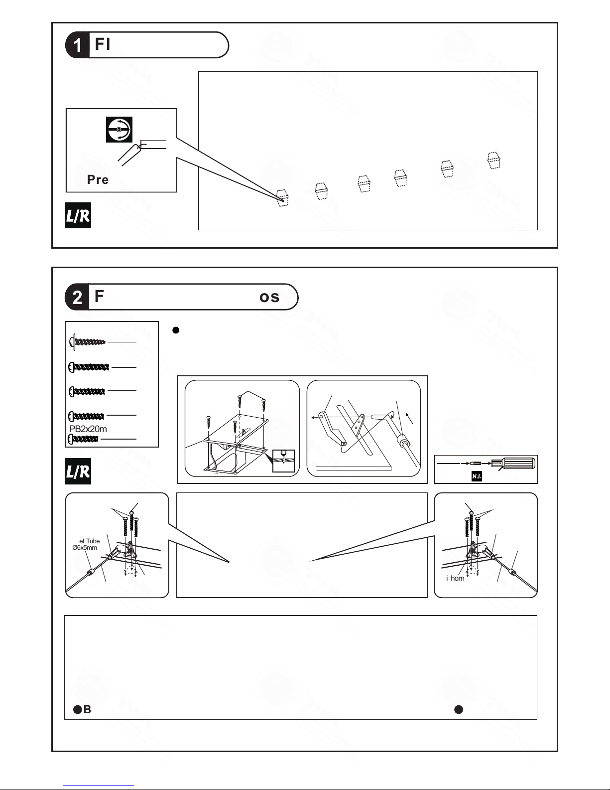
Flap & Aileron
1
Flap & Aileron Servos
2
Pre-glued
PB2x22mm Screw
2
16
PWA2x8mm Screw
PB2x25mm Screw
4
Ø1mm pilot holes for World Models tri-horn are pre-drilled. Please look for
pin-hole marks at under side of control surfaces.
Fuel Tube
Ø6x5mm
PB2x22mm
Tri-horn
M3x14mm(L)
Clevis
Pushrod
Ø1.8x115mm
TWM PL8210010
CLEVIS WRENCH
Straper
Fuel Tube
d2xD4x4mm
PWA2x8mm
1mm
Fuel Tube
Ø6x5mm
PB2x20mm
Tri-horn
M3x14mm
Clevis
Pushrod
Ø1.8x137mm
Bottom View
Completed
P.3
PB2x25mm
PB2x22mm
PB2x20mm Screw
2
PB2x22mm Screw
4
A122PO31681704

L
Retract Servos
R
Whee l
Down
Whee l
up
Whee l
Down
Whee l
up
Push ro d Travel
32mm32mm
Push ro d Travel
Landing Gear & Retract Servos
3
d2xD5mm Washer
24
PM2x8mm Screw
12
M2 Nut
12
Covering
Film
PM2x8mm
d2xD5mm
Washer
Fueslage
4
1
d3.2xD12mm Washer
d2 x D5mm Washer
M2 Nut
2mm
P.4
1
PA3x15mm Screw
d3.2 x D12mm Washer
PA3x15mm
Make sure no glue gets near the pushrod guide sleeves.
A122PO31681704
Fuel Tank
6
Fuel Tank
800c c
P.5
Double-side Tape
40x160mm
Cable Tie 1.5x8x500mm
Completed
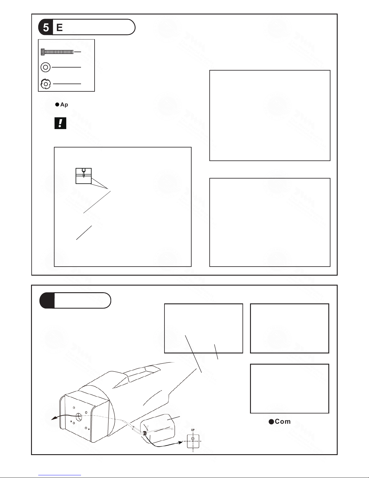
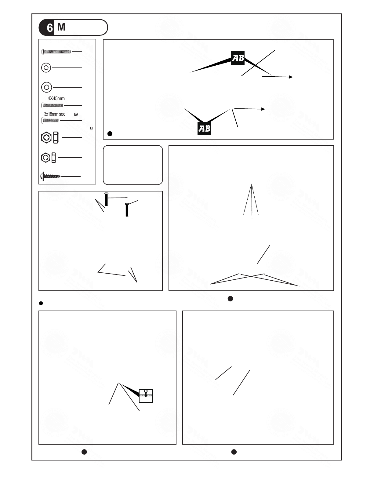
B:Inverted mount for stock muffler
installation.
Engine Mount
5
M6x30mm Screw
4
4
4
d6xD15mm Washer
M6x D18mm Blind Nut
Apply thread locker to screws.
Blind nuts are off-centered
to keep the spinner at the
fuselage axis.
A:Inverted mount with Pitts type muffler.
M6x30mm
Engine Mount
PL5911120
7.5mm
A122PO31681704
Tail Landing Gear
8
3mm Set Screw
2.6mm Collar
2
1
1
PA3x12mm Screw
1.5mm
PA3x12mm
2.6m m
Coll ar
Ø30mm
3mm
Set Sc re w
2mm
P.6
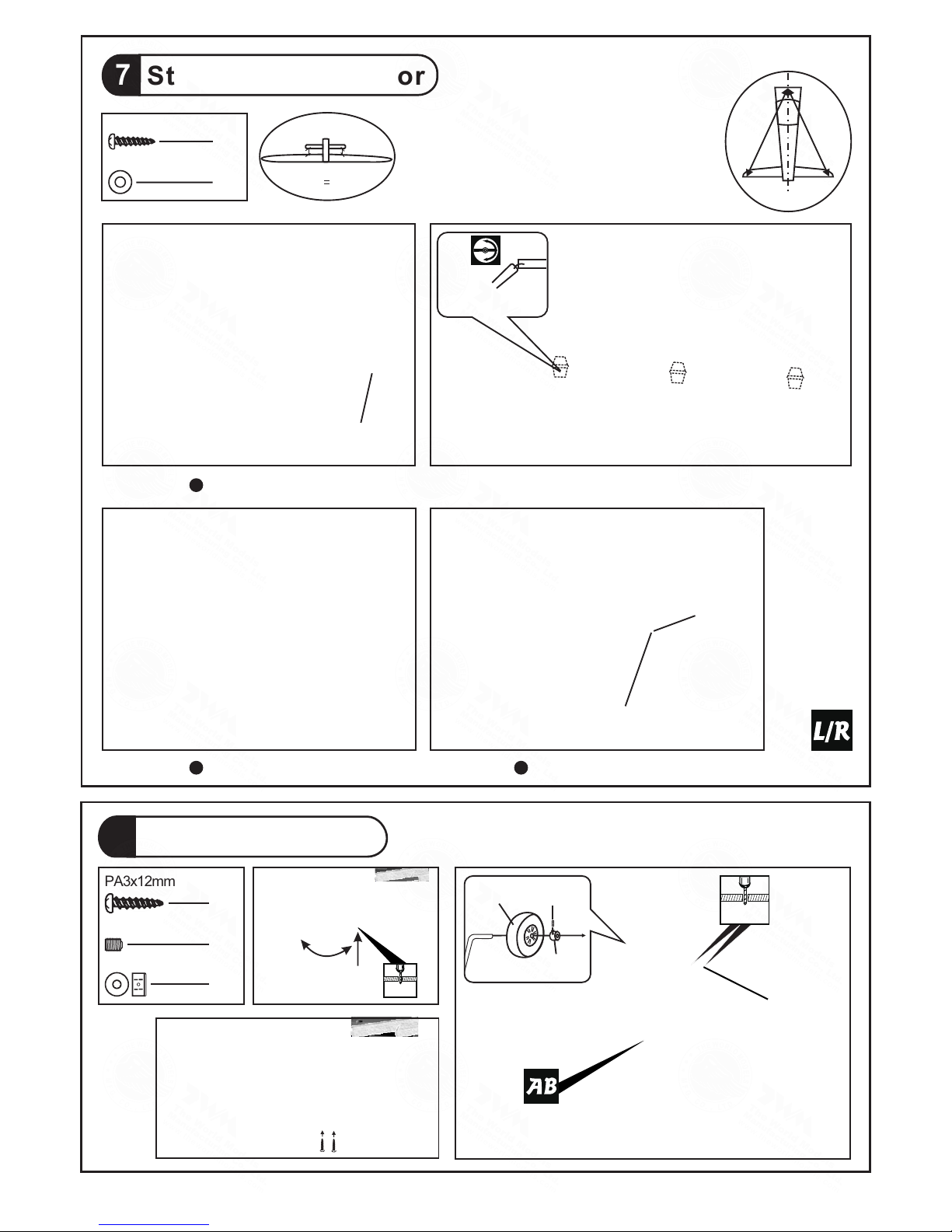
7
Stabilizer & Elevator
2
d3xD7mm Washer
2
PA3x12mm Screw
A A'
A=A'
Bottom ViewBottom View
Bottom View
Pre-glued
Stabilizer Tube
Ø9.5x458mm
PA3x12mm
Washer
d3xD7mm
Tempora r y ins t all t h e main wing, adjust
leveli n g of t he st a bilize r to m ake it as
parall e l to t he mai n wing as pos s ible.
(St abili zer)
(Ma in Wing )
B
B'
B
B'
A122PO31681704

Elevator Pushrod
11
PB2x20mm Screw
4
P.7
9
Vertical Fin & Rudder
Pre-glued
C C'
C=C'
Rudder Pushrod
10
PB2x30mm
Pushrod Ø1.8x970mm
PB2x30mm Screw
3
TWM PL8210010
CLEVIS WRENCH
Ø1mm pilot holes for World Models horn are pre-drilled. Please
look for pin-hole marks at under side of control surfaces.
2mm
Pushrod
Ø1.8x745mm
Ø1mm pilot holes for World Models horn are pre-drilled. Please
look for pin-hole marks at side of control surfaces.
PB2x30mm
Fuel Tube
D6x5mm
Pushrod
Ø1.8x970mm
Clevis
Tri-horn
M3x14mm
PB2x20mm
PB2x18mm
PB2x18mm Screw
2
A122PO31681704

Included w ith the radio Set.
Linkage Connector
M2 Nut
2mm Washer
1
1
1
2
LINKAGE CONNECTOR
Servo Set
12
3 x 3mm Set Screw
Servos
13
Bottom View
Install and arrange the servo as shown in the diagram.
Fuel Tube
Ø6x5mm
Please ref er to the attac hed sheet for linka ge connector i nst allation.
Throttle Pushwire
3x3mm Set Screw
Throttle Servo.
2mm
2mm
Washer
M2 Nut
2mm
Washer
Char ge Re ceptacle s
KP00 413 00
P.8
Elev ato r Servo
Thro ttl e Servo
Rudd er Se rvo
Front
Elevator Servo
Pushrod
Connector
J1(Pushrod Ø1.8x120mm)
J1
J2
Pushrod
Ø1.8x970mm
Pushrod
Ø1.8x745mm
Straper
Rece ive r
Sponge
10x80x200mm
KM 2x8m m
M2 Nut
Eleva to r Pu sh rod
Ø1.8x1 20 mm
Plywood
6x6x41mm
A122PO31681704

PM3 x 10mm
Washer d3 x D7mm
PA3 x 12mm
d2.5 x D8.5 mm Silicon Grommet
2mm
Engine
14
M4 Nylon Insert Lock Nut
4
8
4
8
M4 x 35mm Screw
KM3 x 20mm Screw
d4 x D12mm Washer
Illustration is for inverted mounting.
You can mount the engine upright
or sideways simply by rotation the
engine mount. Thrust angles will
not be affected.
M3 Nylon Insert Lock Nut
5.1 mm
3.2 mm
4.1 mm
3.2 mm
ANT I - VIBR ATI O N MO U N T I N S TA L L AT ION
KM 3 x 2 0 mm
Make sure the rounded edges
are facing the shock absorbing
SILICON PAD.
M4 Nylon Insert Lock Nut
M4 x 35mm
Washer
d4 x D12mm
Thro ttl e Pushw ire
Ø1.2 x36 0mm
Plas tic Tube
d2xD 3x1 10mm
Install En gine position
Cowling
d2.5xD8.5 mm Silicon Grommet
15
d3xD7mm Washer
M3 Nylon Insert Lock Nut
PM3x10mm Screw
PA3x12mm Screw
4
4
4
4
8
First insert the grommet to the
cowling then apply screw.
PM3 x 10mm
Washer
d3 x D7mm
M3
Nylon Insert Lock Nut
Aluminum Plate
8
Spinner
Ø89mm
M3 Nylon Insert Lock Nut
Washer
d3 x D7mm
d2.5xD8.5mm
Silicon Grommet
Fuel Fill er
PL8110030
P.9
A122PO31681704
Main Wing
16
M3 Nylon Insert Lock Nut
2
PWA3x12mm
HM4 x 45mm
d4 x D15mm
Washer
Wing Protection
PM3 x 70mm
d3 x D7mm Washer
M3 Nut
d3 x D7mm Washer
M3
Nut
d3 x D7mm
M3 x 18mm
3mm
Nylon
Insert
Lock
Nut
2
PM3X70mm Screw
8
d3 x D7mm Washer
2
d4 x D15mm Washer
2
2
M3x18mm SOCKET HEAD SCREW
Bottom View
Wing Tube Ø25.4 x 750mm
Wing Tube Ø9.5 x 382mm
Up
Down
2
M3 Nut
PWA3x12mm Screw
3
Bottom View Bottom View
Installation of the optional drop tank.
Bottom View
M3 Nut
d3xD7mm Washer
d3xD7mm
Washer
M3x16mm
2mm
P.10
HM4X45mm Screw
A122PO31681704

Canopy
d1.5xD6.5 mm Silicon Grommet
17
PWA2.3x8mm Screw
8
First insert the grommet the cowling then apply screw.
Apply double-sided tape
Antenna
Sponge
Pilot
Decals
d1.5 x D6.5 mm
Silicon Grommet
Wing Setting
18
Adjust the wing and fuselage configuration as shown in the diagrams.
A = A '
B = B '
C = C '
C C '
A
A '
PWA2.3 x 8mm
8
2mm
P.11
A122PO31681704
Control Throws
C.G.
18mm
18mm
41mm
Elev ato r
Rudd er
50mm
12mm
Aile ron s ( away fr om fu selag e )
Flap s (ne ar fuse lag e )
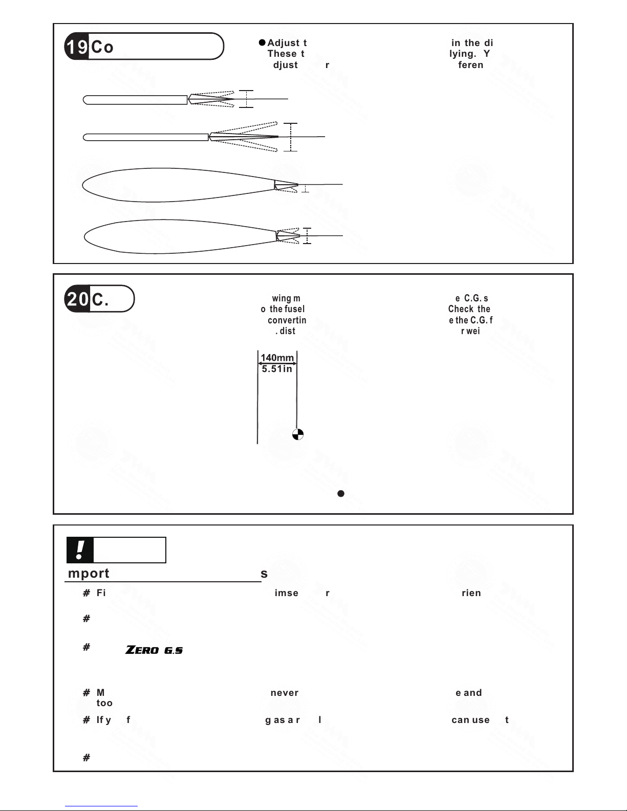
Adjust the control throws as shown in the diagram.
These throws are good for general flying. Yon can
adjust according to your personal preference.
Important Safety Precautions
First time f lyer should never f ly by himself / he rself. Assistance from e xperienced flyer is
absolute ly necessary.
Pre - flight a djustment must be d one before fly ing, it is very dange rous to fly a badly pre adjusted a ircraft.
Make sure th e air field is spacio us, never fly th e plane too close to pe ople and never get
too close to a r unning propelle r.
If y ou find wrinkles on the c overing a s a resu lt of we ather cha nges, you can use hot iron
to remove th e wrinkles. Pleas e begin with low er temperature se tting and gradual ly raise
the temper ature until the wri nkles are gone . Too hot an iron ma y damage the coveri ng.
Check and re -tighten up all fac tory assembl ed screws, use thre ad locker if applic able.
is specially desig ned to be powered by 1.60 2 strok e gl ow engi ne,
using a more powerful engi ne does n ot mean b etter perfo rmance. In fact, over pow ered
engine may c ause severe da mage and injuries .
41mm
12mm
-160
Warning!
P.12
http://ww w.theworldmod el s. co m/ pa ra /i ns tr uc tion/instructio nM an ua ls .p hp
The ide al C.G. pos ition is 14 0mm (5.51 i n) behind t he leadin g edge meas ured at
where t he wing mee ts the fuse lage. In or der to obta in the C.G. s pecifie d, add
weigh t to the fuse lage or mov e the batte ry positi on. Check t he C.G. bef ore flyin g.
If you ar e convert ing this mo del to elec tric, ple ase move th e C.G. forw ard 10% of
curre nt C.G. dis tance fro m leading e dge to comp ensate fo r weight of f uel.
Meas ure C . G.with t he wheels in r etracted p osi tion
A122PO31681704

ADDENDUM
Landing Gear
Should you need to bend the landing gear wire, use the radio control to open
or close the gear to 25% from fully retracted position and switch off the receiver.
It is safe to bend the wire in this position. Bending the wire in fully open position
may damage the supporting structure.
LINKAGE CONNECTOR
HW7111050 & HW7111060
After fastening the round nut, make sure that
the linkage connector can rotate freely.
Drill 2mm hole at servo horn.
Insert linkage connector
into servo horn.
Make sure shoulder of
screw is cleared from
servo horn.
Add washer to reduce
play if necessary.
Shoulder
Tighten up the round nut
against the shoulder. Apply
CA or permanent thread
locker.
P.13
A122PO31681704
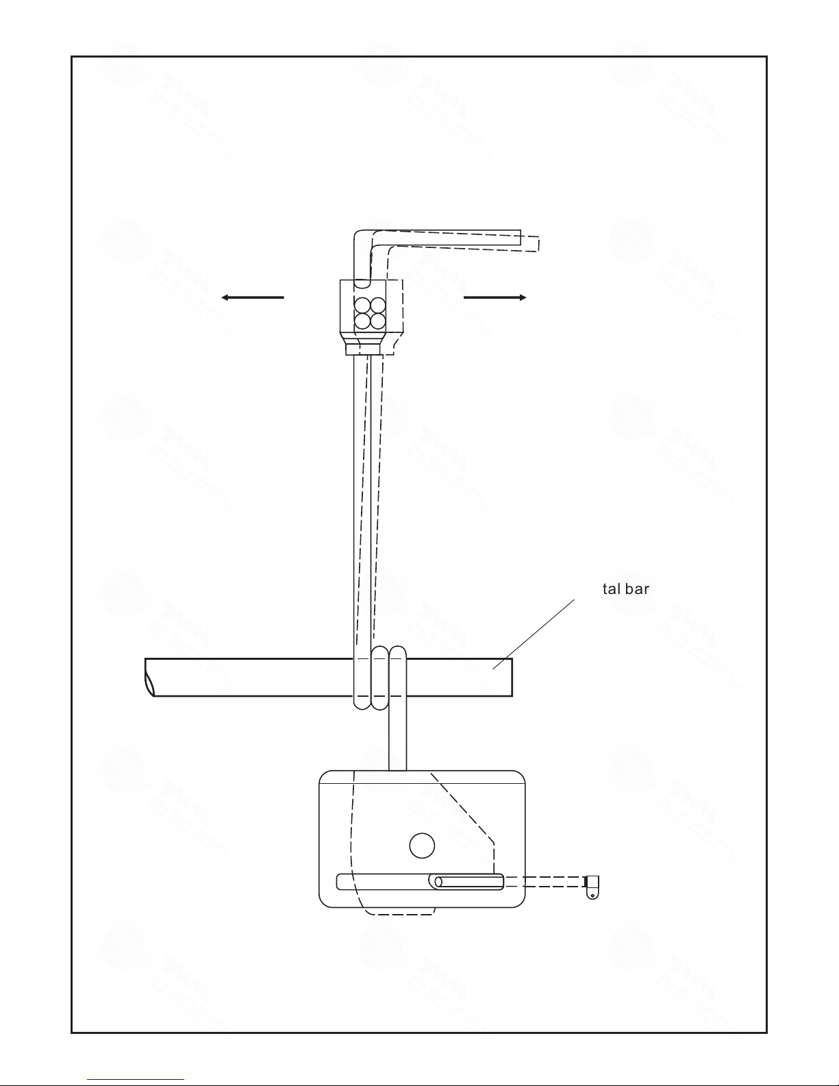
Should you require to bend the landing gear wire, please insert
a round metal bar into the spring coil and apply force there as
leverage. Bending the wire directly may damage the mounting
block structure.
Round metal bar
P.14
A122PO31681704
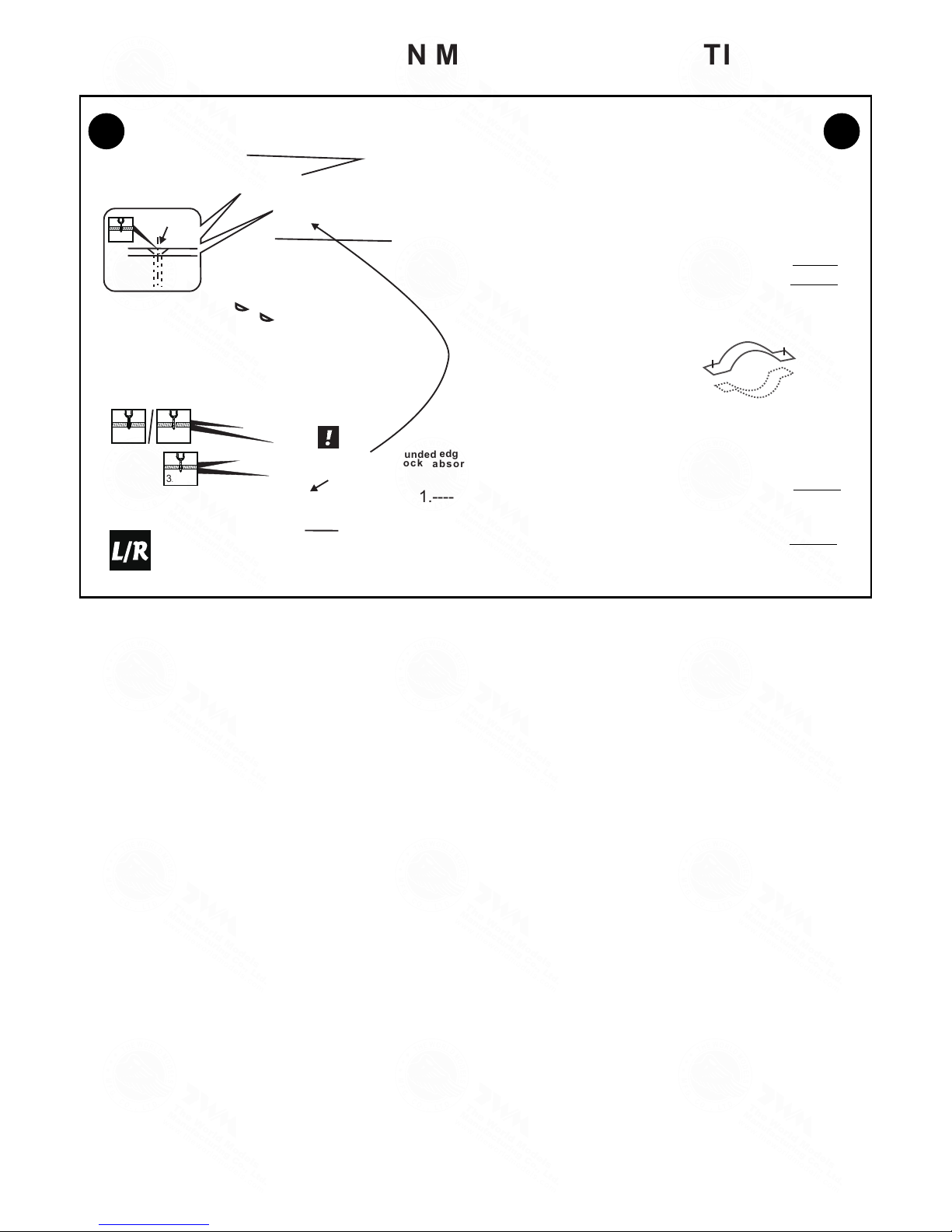
ANTI-VIBRATION MOUNT INSTALLATION
4
5
5
6
For Engine Mount (PL5911120)
1 2
3
Counter Sink
edge s ar e
Make sur e th e ro unded
fa ci ng t he s hock
ab so rbi ng
SILI CON PAD.
1
2
1.----- KM3x20mm Screw
2.----- Copper Tube
3.----- M3 Nylon Insert Lock Nut
4.----- M4 Nylon Insert Lock Nut
5----- 4mm Washer
6.-----M4x35mm Screw
P.15
5.1mm
4.1mm
3.2mm
3.2mm
A122PO31681704

Cod e No.
Siz e
Pac kage
Cod e No.
Siz e
Pac kage
Cod e No.
Siz e
Pac kage
Cod e No.
Siz e
Pac kage
Cod e No.
Siz e
Pac kage
Cod e No.
Siz e
Pac kage
Code N o SV 4031
KP0041300
Special to ol for clevis in stallation.
Suitable f or standard an d small
(EP) clevis.
Larg e Cl evis
Smal l Cl evis
180mm Extension
A122PO31681704
The World Models
Manufacturing Co., Ltd.
www.theworldmodels.com
A122PO31681704
 Loading...