

Page 1
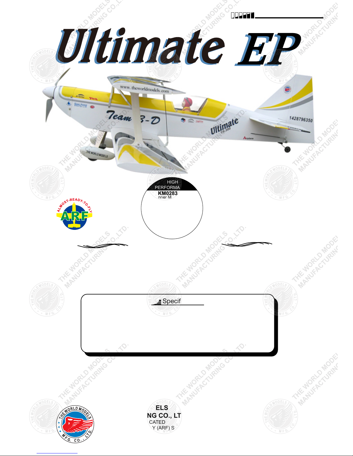
THE WORLD MODELS
MANUFACTURING CO., LTD.
FACTORY PRE-FABRICATED
ALMOST-READY-TO-FLY (ARF) SERIES
MADE IN CHINA
www.theworldmodels.com
Wing Span
Wing Area
Flying Weight
Fuselage Length
36 in / 910 mm
440 sq in / 28.4 sq dm
27 oz / 770 g
38 in / 970 mm
Warning! This model is not a toy.
It is designed for maximum performance. Please seek advice if one is not familiar with this kind
of engine powered precision model. Operating this model without prior preparation may cause
injuries. Remember, safety is the most important thing. Always keep this instruction manual at
hand for quick reference.
HIGH
PERFORMANCE
KM0283010KM0283010
Outrunner Motor Included!
Max Speed 12000 rpm
Operating Power 180 W
Operating Voltage 6-12 V
Peak Current 20 A (max 15 s)
Shaft diameter 3 mm
Diameter 28 mm
Lengthe 30 mm
Weight 60 g
Outrunner Motor
Requires : 4-channel radio w/ 4 micro servos,
20A Brushless ESC, 3 cells 11. 1V
2100mAh Li - Po battery & charger.
Specifications
*Specifications are subject to change without notice.*
INSTRUCTION MANUAL
Page 2

INDEX
BEFORE YOU BEGIN
BEFORE YOU BEGIN
PARTS LIST
ASSEMBLY
SAFETY PRECAUTIONS
P.1
P.2
P.3-P.10
P.10
Check all parts. If you find any defective or missing parts contact your local dealer. Please
DRY FIT and check for defects for all parts that will require CA or Epoxy for final assembly.
Any parts you find to be defective after the gluing process may be difficult to remove for
warranty replacement. The manufacturer will replace any defective parts, but will not extend
to the parts that are good before gluing to defective parts during assembly. Warranty will
not cover any parts modified by customer.
Symbols used throughout this instruction manual comprise of the following :-
Read through the manual before you begin, so you will have an overall idea of what to do.
1
2
3
Apply epoxy glue.
Assemble left and right
sides the same way.
Peel off shaded portion
covering film.
Drill holes with the specified
diameter (here: 3mm)
Pay close attention here!
Pierce the shaded portion
covering film.
Apply instant glue
(C.A.glue, super glue.)
Ensure smooth non-binding
movement while assembling.
Cut off shaded portion.
Must be purchased separately!
Do not overlook this symbol!
3m m
P.1
Page 3
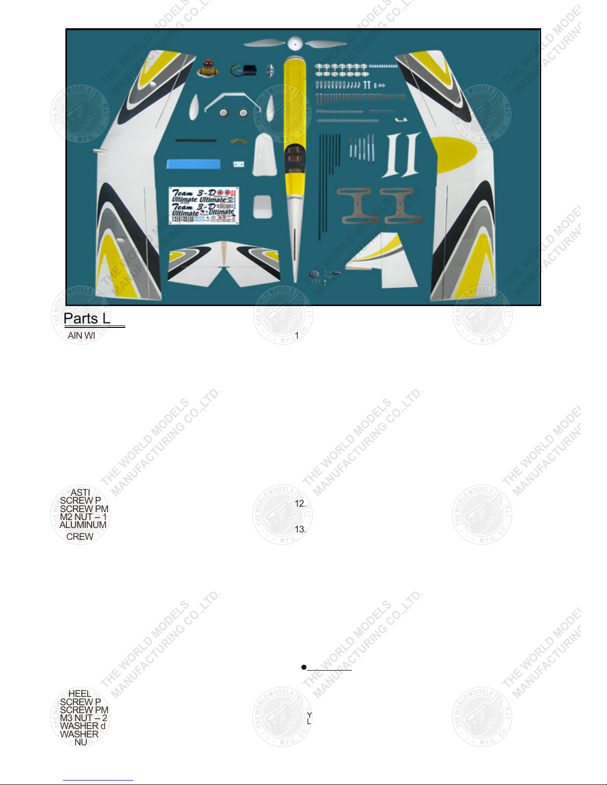
Parts List
P.2
COVERING:-PURPLE COLOR SCHEME:
LIGHTEX SGX100 WHITE
LIGHTEX SGX201 BLACK
LIGHTEX SGX312 BRIGHT RED
LIGHTEX SGX370 SILVER
LIGHTEX SGX561 PEARL PURPLE
YELLOW COLOR SCHEME:
LIGHTEX SGX100 WHITE
LIGHTEX SGX201 BLACK
LIGHTEX SGX312 BRIGHT RED
LIGHTEX SGX370 SILVER
LIGHTEX SGX330 CADMIUM YELLOW
1. MAIN WING (Lower) -- 1 pc.
2. SCREW PM2x12mm -- 4 pcs
FUEL TUBE d2xD4x4mm -- 4 pcs
STRAPER -- 2 pcs
CLEVIS -- 2 pcs
HORN -- 2 sets
PUSHROD Ø1.4x75mm w/ Threads (For Aileron) -- 2 pcs
PLYWOOD 3x6x15mm (For Aileron Servos) -- 4 pcs
3. MAIN WING (Upper) -- 1 pc.
4. STABILIZER & ELEVATOR -- 1 set
FUSELAGE -- 1 pc.
SCREW PM2x8mm -- 2 pcs
ELEVATOR LINK PL4510010 -- 1 pc.
BASLA 4x12x34.7mm -- 1 pc.
5. VERTICAL FIN & RUDDER -- 1 set
6. TAIL LANDING GEAR -- 1 set
TAIL WHEEL Ø23mm -- 1 pc.
PLASTIC COLLAR d1xD5x2mm -- 2 pcs
SCREW PA2x8mm -- 2 pcs
SCREW PM2x8mm -- 1 pc.
M2 NUT -- 1 pc.
ALUMINUM PLATE 0.3x8x22mm -- 1 pc.
7. SCREW PM2x10mm -- 2 pcs
CLEVIS -- 1 pc.
FUEL TUBE d2xD4x4mm -- 1 pc.
HORN -- 1 set
PUSHROD Ø1.4x520mm w/ Threads (For Rudder) -- 1 pc.
8. FUEL TUBE d2xD4x4mm -- 1 pc.
CLEVIS -- 1 pc.
PUSHROD Ø1.4x490mm w/ Threads (For Elevator) -- 1 pc.
9. KM0283010 OUTRUNNER MOTOR -- 1 set
HW2340100 PROPELLER ADAPTOR (d3 D5) -- 1 set
FOLDING PROPELLER SET PL6314020 -- 1 set
SCREW PWA2x8mm -- 4 pcs
SCREW PM3x6mm -- 4 pcs
WASHER d3xD7mm -- 4 pcs
COWLING -- 1 pc.
SPINNER Ø45mm -- 1 set
10. MAIN LANDING GEAR -- 1 pc.
MAIN WHEEL Ø40mm -- 2 pcs
WHEEL PANTS -- 1 pair
SCREW PM2x6mm -- 7 pcs
SCREW PM3x25mm -- 2 pcs
M3 NUT -- 2 pcs
WASHER d3xD7mm -- 2 pcs
WASHER d2xD5mm -- 4 pcs
M2 NUT -- 4 pcs
10. MAIN LANDING GEAR -- 1 pc.
MAIN WHEEL Ø40mm -- 2 pcs
WHEEL PANTS -- 1 pair
SCREW PM2x6mm -- 3 pcs
SCREW PM3x25mm -- 2 pcs
WASHER d2xD5mm -- 7 pcs
WASHER d3xD7mm -- 4 pcs
M3 NUT -- 2 pcs
SCREW PA2x6mm -- 4 pcs
COLLAR Ø3.1mm w/ Set Screw -- 2 sets
COPPER TUBE d3.1xD4x5mm -- 2 pcs
ALUMINUM PLATE 0.5mm -- 2 pcs
11. STRAPER -- 2 pcs
FUEL TUBE d2xD4x4mm -- 2 pcs
SCREW PM2x10mm -- 1 pc.
WASHER d2xD5mm -- 1 pc.
M2 NYLON INSERT LOCK NUT -- 1 pc.
BATTERY TIE -- 1 pc.
SPONGE 10x80x150mm (For Radio Equipment) -- 1 pc.
DOUBLE-SIDED TAPE 30x35mm -- 1 pc.
MOUNTING PLATE 5x15mm PL4114015 -- 1 pc.
PLYWOOD 2x56x96mm -- 1 pc.
12. CANOPY -- 1 pc.
SCREW PWA2x8mm -- 4 pcs
PILOT (050) -- 1 pc.
13. NYLON BOLT M2.5x20mm -- 2 pcs
NYLON WASHER d2.6xD9mm -- 2 pcs
PLASTIC PLATE 1x25.5x63.7mm (Wing Protection) -- 1 pc.
14. SCREW PWA2.3x12mm -- 4 pcs
SCREW PM2x14mm -- 2 pcs
SCREW PM2x8mm -- 4 pcs
WASHER d2xD5mm -- 12 pcs
M2 NYLON INSERT LOCK NUT -- 6 pcs
PLYWOOD 3x53x170mm (Side Cabane) -- 2 pcs
FOAM 3x204x209mm (Wing Incidence Angle Template) -- 2 pcs
ALUMINIUM PLATE (Brace: Fueslage to Wing) -- 1 set
15. SCREW PM2x8mm -- 8 pcs
HORN -- 4 sets
CLEVIS -- 4 pcs
FUEL TUBE d2xD4x4mm -- 4 pcs
PUSHROD Ø1.4x138mm w/ Threads (For Aileron to Aileron) -- 2 pcs
16. DECALS -- 1 set
Page 4
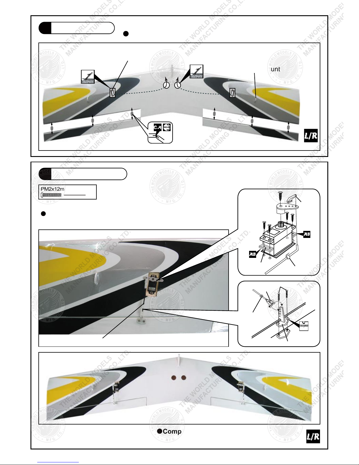
Main Wing
(Lower)
Apply instant type CA glue to both sides of each hinge.
Completed
Aileron Servo
(Lower)
Aileron Servo Lead
Cabane Mount
PM2x12mm Screw
4
Clevis
Horn
Straper
PLYWOOD
3x6x15mm
Fuel Tube
d2xD4x4mm
Fuel Tube
d2xD4x4mm
PM2x12mm
Pushrod Ø1.4x75mm
2mm
Ø1mm pilot holes for World Models tri-horn are pre-drilled.
Please look for pin-hole marks at side of control surfaces.
P.3
2
1
Page 5
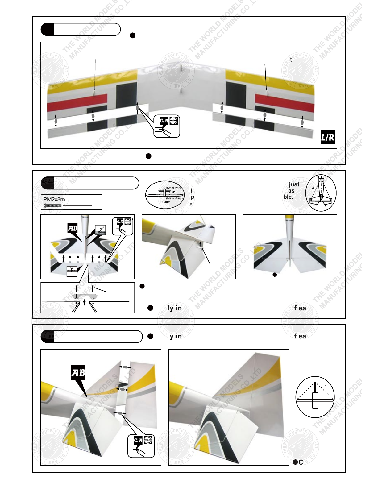
Vertical Fin & Rudder
Temporary install the main wing, adjust
leveling of the stabilizer to make is as
parallel to the main wing as possible.
Ø1mm pilot holes for World Models tri-horn are pre-drilled.
Please look for pin-hole marks at side of control surfaces.
*Also refer to step 13 Wing Setting
(Stabilizer)
(Main Wing)
B
B=B
B
A=A
A A
2mm
c=c'
c
c
P.4
5
PM2x8mm Screw
PM2x8mm
Balsa
4x12x34.7mm
Stabilizer & Elevator
2
4
Main Wing
(Upper)
Apply instant type CA glue to both sides of each hinge.
Apply instant type CA glue to both sides of each hinge.
Apply instant type CA glue to both sides of each hinge.
Cabane Mount
Cabane Mount
3
Bottom View
Completed
Completed
Page 6
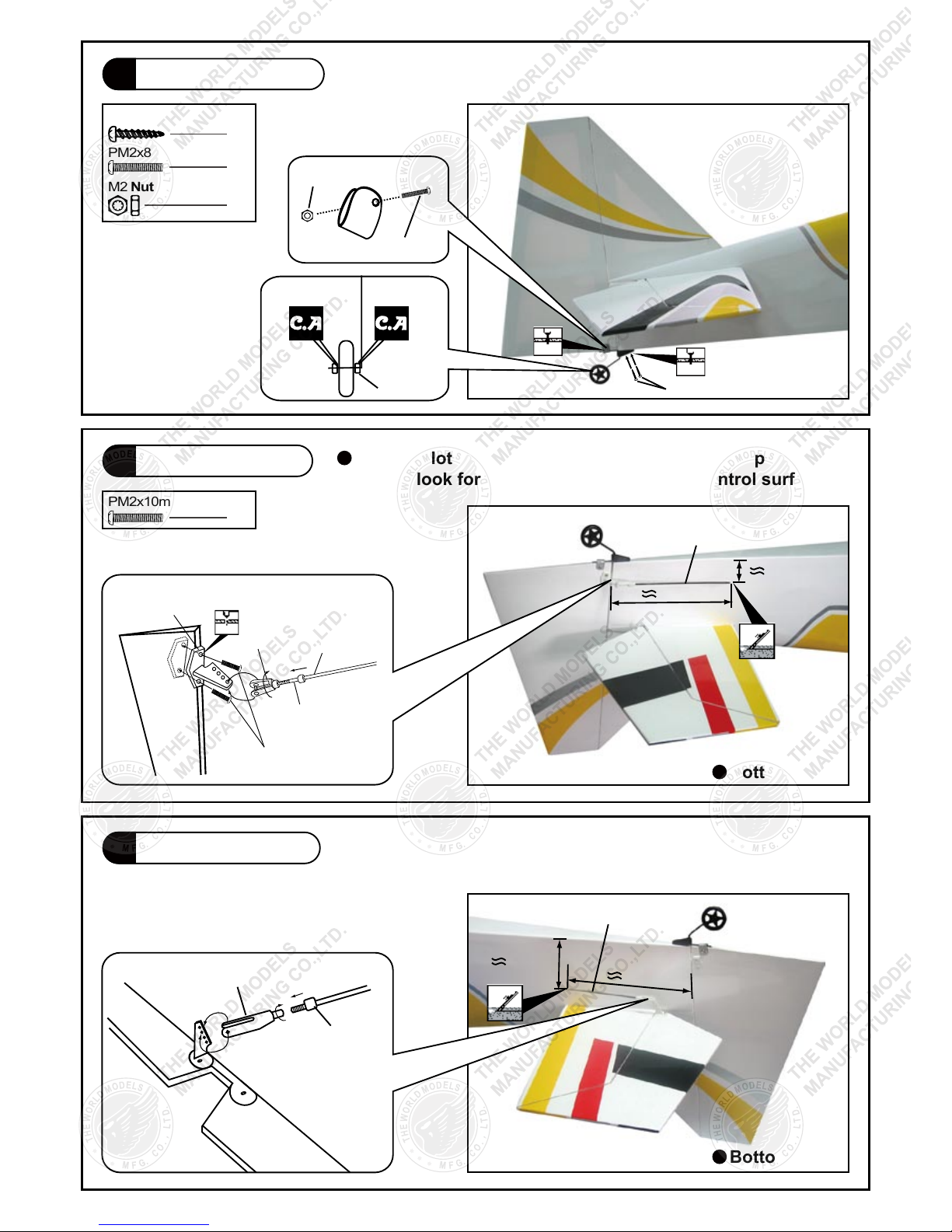
Tail Landing Gear
PA2x8mm Screw
PA2x8mm
PM2x8mm Screw
PM2x8mm
Bottom View
Bottom View
Elevator Pushrod
Rudder Pushrod
M2 Nut
M2 Nut
PM2x10mm Screw
Plastic Collar
1mm
1mm
27mm
125mm
57mm
130mm
Clevis
Horn
Fuel Tube
d2xD4x4mm
PM2x10mm
Pushrod
Ø1.4x520mm
Pushrod
Ø1.4x520mm
2mm
Pushrod
Ø1.4x490mm
Clevis
Fuel Tube
d2xD4x4mm
P.5
2
1
1
2
7
8
6
Ø1mm pilot holes for World Models tri-horn are pre-drilled.
Please look for pin-hole marks at side of control surfaces.
Page 7
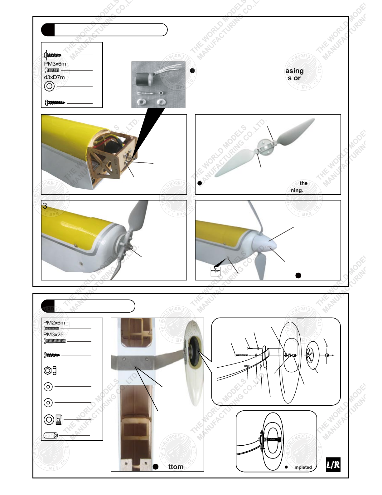
Outrunner Motor / Cowling
PM3x6mm Screw
d3xD7mm
Washer
PWA2x8mm Screw
4
PA2.6x8mmScrew
2
Completed
Main Landing Gear
3.1mm
Wheel Collar
10
PM2x12mm
PM2x12mm
PM3x6mm
d3xD7mm
Washer
PA2.6x8mm
PWA2x8mm
Don’t over-tighten the PM2 screws, let the propeller
blades align themselves when spinning.
1. 5mm
Ø45mm Spinner
M5 Nut
43
21
Bottom View
PM3x25mm Screw
d3xD7mm Washer
M3 Nut
PM2x6mm Screw
PM2x6mm
d2xD5mm
Washer
PA2x6mm Screw
d2xD5mm Washer
Completed
Make sure rotating motor casing
is not in contact with wirings or
anything.
d3.1xD4x5mm Copper Tube
2
PM3x25mm
Plate 0.5mm
PA2x6mm
PA2x6mm
Copper Tube
d3.1xD4x5mm
d3xD7mm Washer
d2xD5mm Washer
d3xD7mm Washer
d2xD5mm Washer
Wheel
Ø40mm
3mm
Set Screw
3.1mm
Collar
M3
P.6
4
4
9
3
4
4
7
2
2
2
Page 8
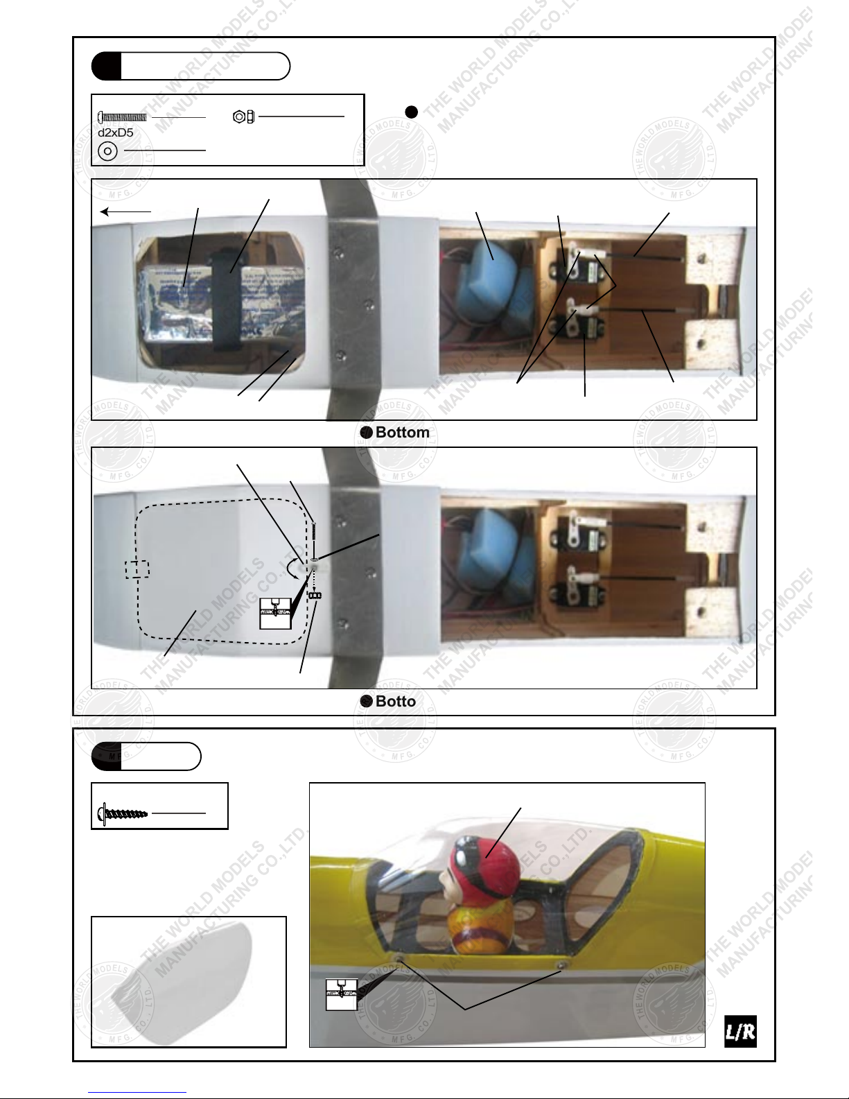
Radio Equipment
PWA2x8mm Screw
PWA2x8mm
Bottom View
Bottom View
Canopy
Front
Install and arrange the servo as shown
in the diagram.
Battery
Double-Sided Tape
Mounting Plate
PM2x10mm
PLYWOOD 2x56x96mm
M2 Nylon Insert Lock Nut
M2 Nylon Insert Lock Nut
Straper
Pilot
Rudder Servo
Sponge
Rudder Pushrod
Elevator Pushrod
Elevator Servo
d2xD5mm
Washer
Fuel Tube
d2xD4x4mm
20A Speed Controller
Battery Tie
1mm
2mm
PM2x10mm Screw
d2xD5mm Washer
1
1
1
P.7
4
12
11
Page 9
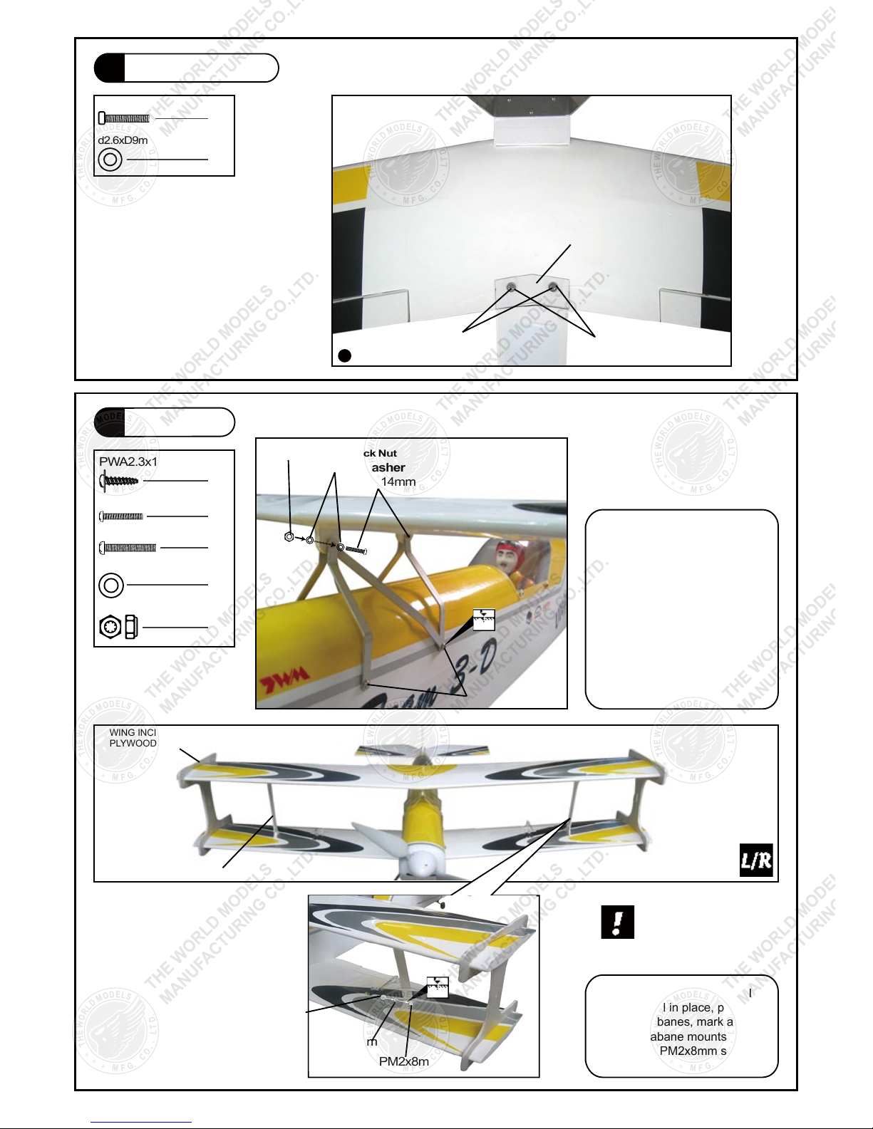
Main Wing
(Lower)
M2.5x20mm Nylon Bolt
M2.5x20mm Nylon Bolt
Wing Protection
1x25.5x63.7mm
d2.6xD9mm Nylon Washer
d2.6xD9mm Nylon Washer
Bottom View
Main Wing
PM2x8mm Screw
PM2x8mm
PWA2.3x12mm Screw
PWA2.3x12mm
PM2x14mm Screw
PM2x14mm
With the wing incidence angle
template still in place, position
the side cabanes, mark and drill
the side cabane mounts and
fasten with PM2x8mm screw
and nut.
Pierce the two pre-drill holes
at upper wing center cabane
mount and fasten the center
cabanes with PM2x14mm
screw and nut. With the lower
wing fastened to the fuselage,
insert the wing incidence angle
templates to both sides of upper
and lower wing to hold the upper
wing in position. Mark and drll
1.5mm pilot holes at the fuselage
and fasten the center cabane
with PWA2.3x12mm screws.
Outer wing cabane
should fit to the outside
of outer wing cabane
mounts.
SIDE CABANE
PLYWOOD 3x53x170mm
WING INCIDENCE ANGLE TEMPLATE
PLYWOOD 3x204x209mm
d2xD5mm Washer
d2xD5mm Washer
d2xD5mm
Washer
M2 Nylon Insert Lock Nut
M2 Nylon Insert Lock Nut
M2 Nylon Insert Lock Nut
6
1. 5mm
2mm
P.8
2
2
12
4
2
4
14
13
Page 10
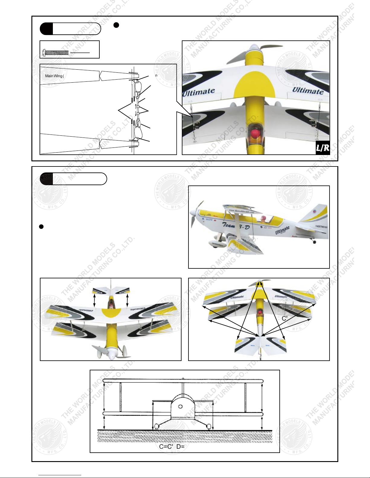
Main Wing
PM2x8mm Screw
Wing Setting
PM2x8mm
Fuel Tube
d2xD2x4mm
Clevis
Clevis
Horn
Horn
Pushrod
Ø 1.4x138mm
MainWing(Upper)
MainWing(Lower)
Ø1mm pilot holes for World Models tri-horn are pre-drilled.
Please look for pin-hole marks at under side of control surfaces.
Adjust the wing and fuselage configuration
as shown in the diagrams.
A
A'
B'B
C'
D'
E'
A=A' B=B' C=C' D=D' E=E' F=F' G=G'
G' F'F G
C
D
E
P.9
8
16
15
Page 11
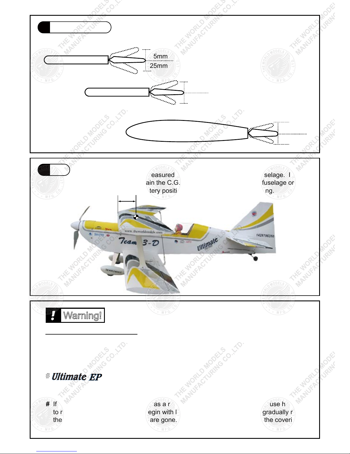
Control Throws
C.G.
Adjust the control throws as shown in the
diagram. These throws are good for general
flying. You can adjust according to your
personal preference.
Elevator
Rudder
25mm
25mm
15mm
5mm
5mm
15mm
Aileron
The ideal C.G. position is 83mm (3.25 in) behind the leading
edge measured at where the wing meets the fuselage. In order
to obtain the C.G. specified, add weight to the fuselage or move
the battery position. Check the C.G. before flying.
83mm
C.G.
3.25 in
# First time flyer should never fly by himself/herself. Assistance from experienced flyer is
absolutely necessary.
# Pre-flight adjustment must be done before flying, it is very dangerous to fly a badly
pre-adjusted aircraft.
# Check and re-tighten up all factory assembled screws, use thread locker if applicable.
# Make sure the air field is spacious, never fly the plane too close to people and never get
too close to a running propeller.
# If you find wrinkles on the covering as a result of weather changes, you can use hot iron
to remove the wrinkles. Please begin with lower temperature setting and gradually raise
the temperature until the wrinkles are gone. Too hot an iron may damage the covering.
# is specially designed to be powered by KM0283010 Outrunner Motor.
Warning!
Important Safety Precautions
E25107 04
P.10
18
17
Page 12
http://www.theworldmodels.com
E25107 04
 Loading...