

Page 1
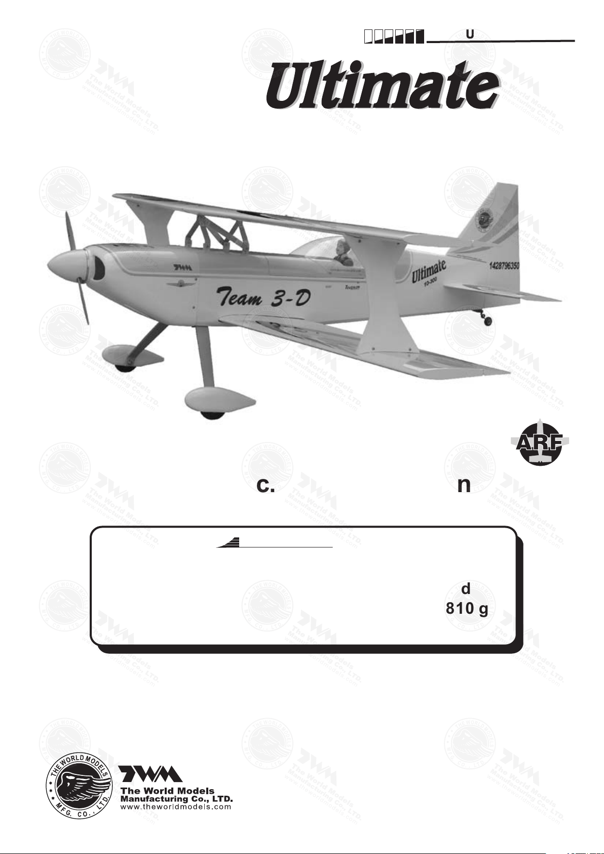
27%27%
INSTRUCTION MANUAL
A
E
D
R
-
T
S
O
M
L
A
Requires : 50 c.c. engine, 4 - channel radio
w/ 8 high torque servos.
Specifications
Wing Span
Wing Area
Flying Weight
Fuselage Length
* Specificatio ns are su bject to change withou t notic e.*
63 in / 1600 mm
1420 sq in / 91.6 sq dm
13-15 lbs / 5900-6810 g
66.5 in / 1690 mm
Warning !This model is not a toy.
It is designed for maximum performance. Please seek advice if one is not familiar with this kind
of engine powered precision model. Operating this model without prior preparation may cause
injuries. Remember, safety is the most important thing. Always keep this instruction manual at
hand for quick reference.
Y
-
T
O
-
F
L
Y
ALMOST-READY-TO-FLY (ARF) SERIES
FACTORY PRE-FABRICATED
MADE IN CHINA
Page 2
IND E X
BEFORE YOU BEGIN
PARTS LIST
ASSEMBLY
SAFETY PRECAUTIONS
BEFORE YOU BEGIN
Read through the manual before you begin, so you will have an overall idea of what to do.
1
Check all parts. If you find any defective or missing parts contact your local dealer. Please DRY FIT
2
and check for defects for all parts that will require CA or Epoxy for final assembly. Any parts you
find to be defective after the gluing process may be difficult to remove for warranty replacement. The
manufacturer will replace any defective parts. but will extend to the parts that are good before
gluing to defective parts during assembly.
not
P. 1
P. 2
P. 3 - 14
P. 14
Symbols used throughout this instruction manual comprise of the following : -
3
Apply instant glue
(C.A.glue, super glue.)
Must be purchased separately!
Ensure smooth non-binding
movement while assembling.
Cut off shaded portion.
Pierce the shaded portion
covering film.
3mm
Apply epoxy glue.
Apply thread locker
Assemble left and right
sides the same way.
Peel off shaded portion
covering film.
Drill holes with the specified
diameter (here: 3mm).
Pay close attention here!
P.1
Warning!
Do not overlook this symbol!
Page 3
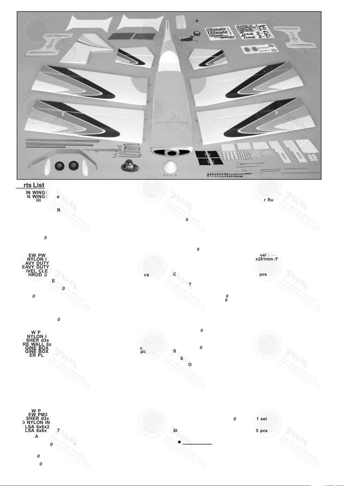
Parts List
1.MAIN WING(Upper Wing) -- 1 pair
MAIN WING(Lower Wing)-- 1 pair
METAL HINGES -- 28 pcs
2.SERVO MOUNTING PANEL ( For Aileron Servo ) -- 1 pair
HEAVY DUTY SERVO HORN PL4120350
SCREW PM4x50mm -- 2 pcs
SCREW PWA2x12mm -- 8 pcs
M4 NYLON INSERT LOCK NUT -- 2 pcs
HEAVY DUTY HORN BRACKET PL4112400 -- 2 sets
HEAVY DUTY CLEVIS PL412200 -- 4 sets
SWIVEL CLEVIS HORN FAIRING PL4610010 -- 2 sets
PUSHROD
3 .SERVO M OUNTING P ANEL(For A ileron ) -- 1 p air
H EAVY D UTY S ERVO H ORN P l4120350 -- 2 s ets
S CREW P M4x50mm - - 2 p cs
S CREW P WA2x12mm - - 8 p cs
M 4 N YLON I NSERT L OCK N UT -- 2 p cs
H EAVY D UTY H ORN B RACKET P L4112400 -- 2 s ets
H EAVY D UTY C LEVIS P L412200 -- 4 s ets
S WIVEL C LEVIS H ORN F AIRING P L4610010 -- 2 s ets
P USHROD 2.5x70mm w /Threads ( For A ileron ) --2 p cs
4.STABILIZER & ELEVATOR -- 1 set
F USELAGE -- 1 p c.
STABILIZER TUBE 14.5x319mm -- 1 pc.
SCREW PWA3x12mm -- 2 pcs
WIRE 3 x186mm -- 1 pc.
METAL HINGES -- 8 pcs
5.VERTICAL FIN & RUDDER -- 1 set
METAL HINGES -- 5 pcs
6.TAIL LANDING GEAR -- 1 set
RUDDER WHEEL 30mm -- 1 pc.
COLLAR 2.6mm w/set screw -- 1 set
SCREW PA3x12mm -- 2 pcs
7.SCREW PM3x13mm 8 pcs
--
M3 NYLON INSERT LOCK NUT 8 pcs
--
WASHER d3xD7mm 16 pcs
--
FIRE WALL 6x115x120mm F9 1 pc
( ) -- .
ENGINE BOX SIDE PLATE 4x90x361 5mm F8 1 pc
. ( ) -- .
ENGINE BOX SIDE PLATE 4x90x366 5mm F8 1 pc
. ( ') -- .
LOWER PLATE 3x120x135 5mm F8B 1 pc
. ( ) -- .
BALSA 5x5x80mm F9A 1 pc
( ) -- .
BALSA 5x5x129 5mm F9B 2 pcs
. ( ) --
BALSA 5x5x123 7mm F9B 2 pcs
. ( ') --
BALSA 5x5x90mm F9C 2 pcs
( ) --
BALSA 5x5x80mm F9D 1 pc
( ) -- .
PLYWOOD 4x15x153 5mm F48 4 pcs
. ( ) --
PLYWOOD 4x15x64mm F49 4 pcs
( ) --
BAMBOO D3 5x380mm 1 pc
. -- .
PLYWOOD 4x20x134mm F26 2 pcs
( ) --
PLYWOOD 4x20x134mm F26A 2 pcs
( ) --
BALSA 5x5x50mm(F53) -- 2 pcs
BALSA 6x6x112mm(F53A) -- 1 pc.
CENTER WING CABANE 1 set
8. --
SCREW PM3x13mm
SCREW PM3x16mm 1 pc
-- .
WASHER d3xD7mm 12 pcs
--
M3 NYLON INSERT LOCK NUT 6 pcs
--
B ALSA 6x6x241.1mm(F18B) -- 2 pcs
BALSA 6x6x246.7mm(F18C) -- 2 pcs
9.MAIN LANDING GEAR -- 1 pair
SOCKET HEAD SCREW M5x16mm 4 pcs
- -
AXLE SHAFT 4x54mm 2 pcs
--
WHEEL PANTS -- 1 pair
SCREW PA3x12mm -- 4 pcs
WHEEL 76mm -- 2 pcs
M8 NYLON INSERT LOCK NUT 2 pcs
--
COLLAR 4.1mm w/set screw --
2.5x70mm
w/Threads(For Aileron) -- 2
5 pcs
--
sets
4
-- 2
sets
pcs
10.
SCREW M4x80mm
.
M4
NYLON INSERT LOCK NUT
EYE SCREW M2.5x8x25mm w/Threads(For Rudder
HEAVY DUTY HORN BRACKET PL4112400
HEAVY DUTY CLEVIS PL4112400
SWIVEL CLEVIS HORN FAIRING PL4610020
COPPER TUBE d2.5xD3.2x8mm(For Rudder)
WIRE 1x800mm(For Rudder)
SCREW PM4x70mm
11.
M4 NYLON INSERT LOCK NUT 2 pcs
--
HEAVY DUTY HORN BRACKET PL4112400 2 sets
--
HEAVY DUTY SERVO HORN PL412035 2 sets
--
HEAVY DUTY CLEVIS PL4112200 4 sets
--
SWIVEL CLEVIS HORN FAIRING PL4610010 2 sets
--
PUSHROD
FUEL TANK 650cc PL11165G Gasoline Fuel 1 set
12.
( -- .
--
--
--
( ) --
1 3.BLIND N UT M 6 -- 4 p cs
S OCKET H EAD S CREW M 6x20mm
W ASHER d 6xD15mm -- 4 p cs
U PPER C ONNECTOR 3 x120x129.5mm(F8C) --1 p c
L INKAGE C ONNECTOR 2. mm
T HROTTLE P USHWIRE 1.2x520mm
w /Plastic T ube d 2xD3x300mm
14.H EAVY D UTY S ERVO H ORN P L4120800
H EAVY D UTY C LEVIS P L4112200 -- 2 s ets
E YE S CREW M 2 5.x8x25mm w /Threads(For R udder) -- 2 p cs
C OPPER T UBE d 2.5xD3.2x8mm(For R udde r)-- 2 p cs
S PONGE 1 0x80x200mm
15.W ING T UBE 14.5x806mm -- 1 p c.
S CREW P M3x16mm - - 1 p c.
S CREW P A3x16mm - - 1 p c.
W ASHER d 3xD7mm -- 2 p cs
1 6.WING T UBE 14 .5x645mm - - 1 p c.
S CREW P M3x16mm - - 1 p c.
S CREW P A3x16mm - - 1 p c.
W ASHER d 3xD7mm -- 2 p cs
1 7.PLYWOOD(OUTER W ING C ABANE S) -- 1 p air
P LYWOOD 3 x330 .8x388.6mm( Wing I ncidence A ngle T empla te) -- 2 p cs
S CREW P M3x18mm -- 8 p cs
W ASHER d 3xD7mm -- 1 6 p cs
M 3 N YLON I NSERT L OCK N UT - - 8 p cs
1 8.CANOPY -- 1 p c.
C OCKPIT -- 1 p c.
P ILOT P C001085A/B -- 1 p c .
S CREW P WA 2 .3x8mm -- 4 p cs
S CREW P M3x16mm - - 2 p cs
W ASHER d 3xD7mm - - 2 p cs
S ILICON G ROMMET d 1.5xD6. 5mm -- 4 p cs
1 9.COWLING -- 1 p c.
S PINNER(w/alu.back p late) 89mm -- 1 s et
S CREW P A3x12mm -- 5 p cs
W ASHER d 3xD7mm -- 5 p cs
S ILICON G ROMMET d 2.5xD8.5mm -- 5 p cs
2 0.DECALS -- 1 s et
P.2
( ) --
FUEL TANK HOLD DOWN PLATE 3x95x281mm F2A 1 pc
SCREW PM3x12mm 2 pcs
WASHER d3xD7mm 2 pcs
SPONGE 10x80x200mm 1 pc
CABLE TIE 400mm For Fuel Tank 2 pcs
COVERING:--
PURPLE COLOR SCHEME:
TOUGHLON STL 100 WHITE
TOUGHLON STL 201 BLACK
TOUGHLON STL 561 PEARL PURPLE
TOUGHLON STL 370 SILVER
-
1 pc
-
--
x145mm w/Threads(For Elevator 2 pcs
2
.
5
2 pcs
-
-
-- 2
pcs
-- 2
sets
sets
2 p cs
--
1 s et
1 p c
--
--
-
-
YELLIOW COLOR SCHEME:
TOUGHLON STL 100 WHITE
TOUGHLON STL 201 BLACK
TOUGHLON STL 330 CADMIUM YELLOW
TOUGHLON STL 370 SILVER
1
1 p c
-- 2
-- 2
.
--
.
-- 2
-- 2
.
1 p c
1 s et
sets
sets
)
.
--
) -- 2
sets
)
.
pcs
Page 4
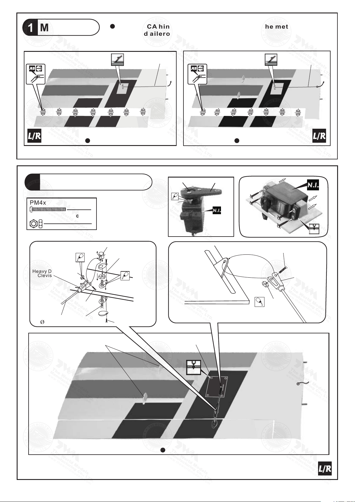
Main Wing
M2 Nut
PM2x8 mm
Heavy Duty
Clevis
1
Replace C A hin g e s by met a l hinges. G l u e the me t a l hinges t o
wing and a il eron by e p o xy.
Main Win g (Lowe r)
Aileron Servo
2
PM4x50mm Screw
M4 N ylon Inse rt Lock Nut
Bottom View
(Upper Wing)
2
2
Aile ron S erv o Lea d
PM 2 x 12 mm
M2 Nut
Main Win g (Uppe r)
Aile ron S erv o Lea d
Bottom View
PL41 203 50
1.5mm
Heav y Dut y
Clev is
Pushrod
2.5x70mm
Heav y Du ty H orn B ra ck et
Lock Nu t
M2 Nut
PM2x 8m m
PM4 x 50 mm
PM4 x 50 mm
Outer wing cabane mounts
PA1. 7x8 mm
M4 Nylo n Inse rt
PWA 2 x1 2mm
1.5m m
Bottom View
P.3
Page 5
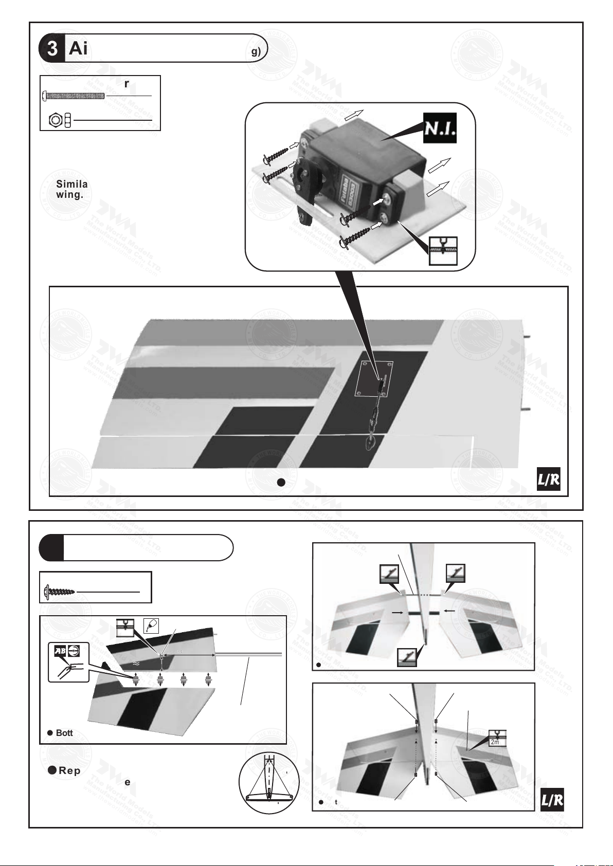
Aileron Servo (Lower Wing)
1.5mm
Wire Ø3 x1 86 mm
Bottom View
3
PM4x50mm Screw
2
M4 N ylon Inse rt Lock Nut
2
Similar installation as upper
wing.
Stabilizer & Elevator
4
PWA3 x 12mm Screw
2
2mm
Bottom View
PWA 3x 12mm
40mm
Replace C A hin g e s by met a l
hinges. G l u e the me t a l hinges
to stabi l i z e r and el e v a tor by
epoxy.
130m
m
Stabilizer Tube
Ø14. 5x 319mm
Bottom View
M3 x 6mm S et Scre w
A
A
A=A
Bottom View
M3 x 6mm S et Scre w
M3 x 6mm S et Scre w
PWA 3 x 12mm
2mm
M3 x 6mm S et Scre w
P.4
Page 6
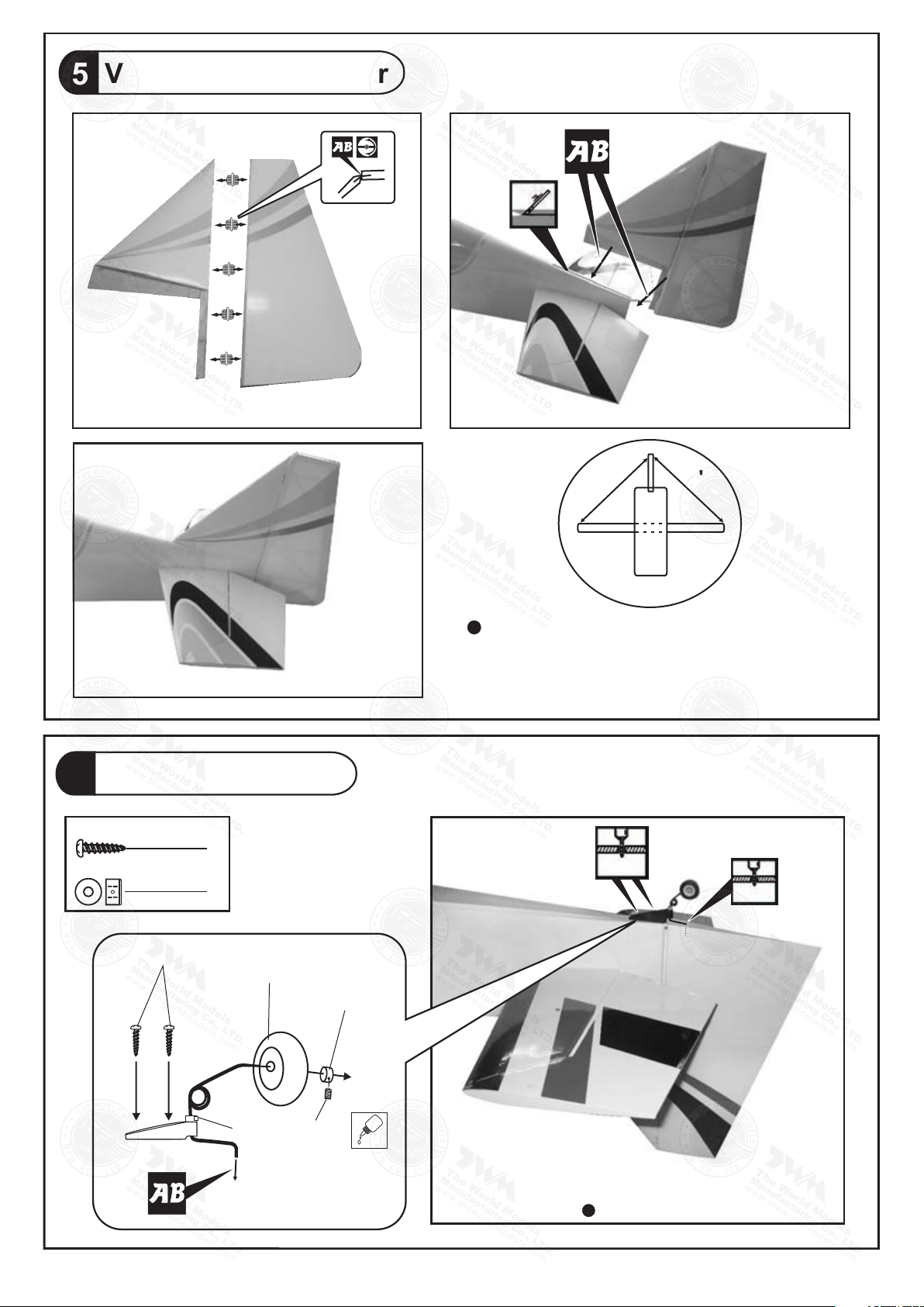
Vertical Fin & Rudder
5
B B'
Completed
Tail Landing Gear
6
PA3 x 12mm Screw
2
2.6mm Collar
1
PA3 x 12mm
Rubber Tail Wheel
Ø30mm
B=B'
Replac e CA hinges by metal
hinges . Gl ue t he metal h ing es
to vert ica l and rudder by epoxy.
1.5mm
2.5mm
2.6mm Collar
M3 x 3mm Set Screw
Bottom View
P.5
Page 7
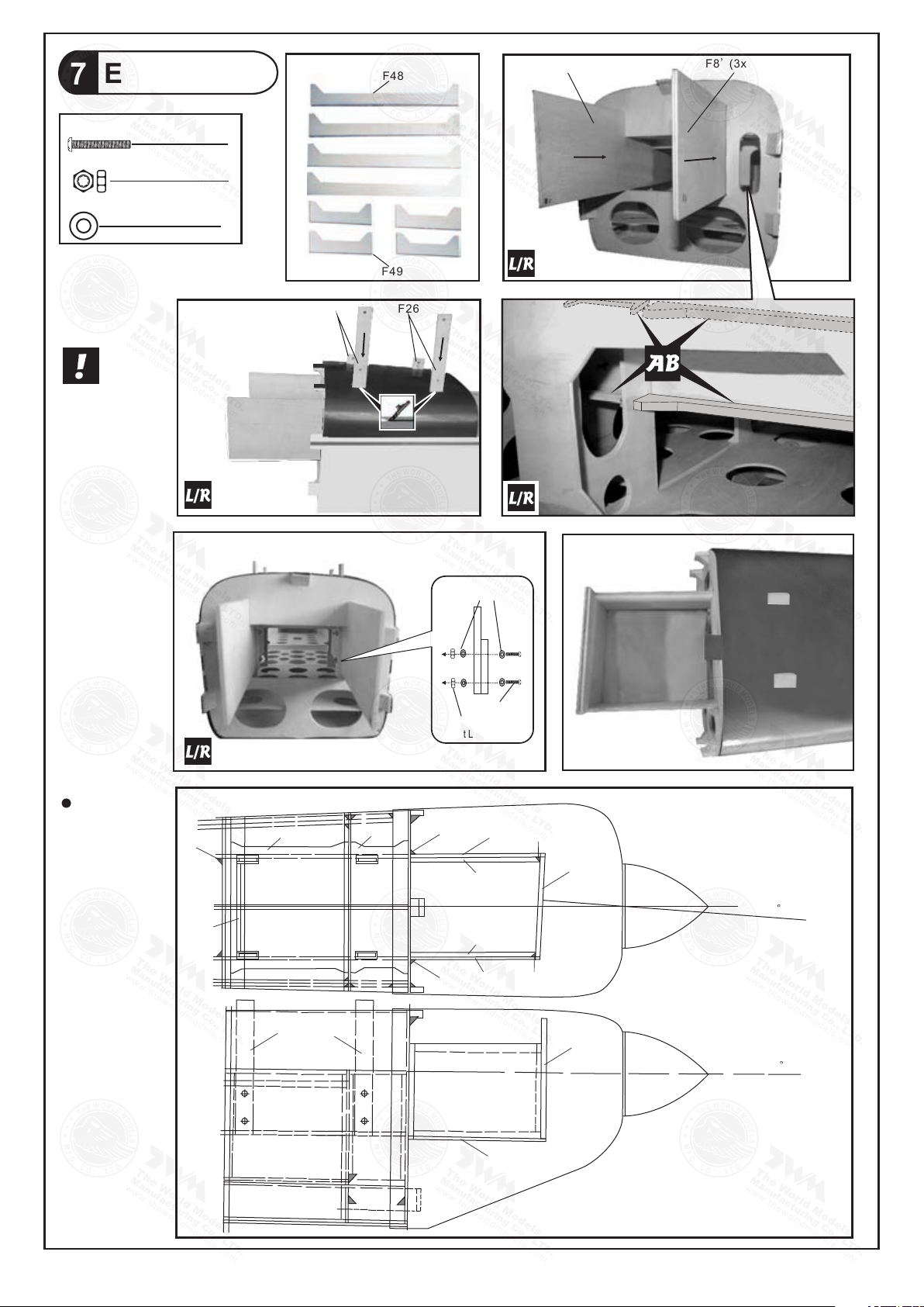
Engine Box
7
PM3x13mm Screw
M3 N ylon Inse rt Lock Nut
d3xD7mm Washer
16
F48
F8 (3x 90x36 1.5mm )
F8' (3 x90x3 66.5m m)
8
8
F49
Please note
right thrust
angle of
firewall.
F26A
F26
d3xD 7m m
Was he r
PM3x 13 mm
M3 Nyl on
Inse rt L oc k Nut
Use epo xy to
glue al l part s
toget her.
F53
F53 A
F26
F48
F26A
F49
F9C
F9C
F8'
F9B'
F9B
F8
Completed
F9D
F9
2
F9A
F9
0
F8B
P.6
Page 8
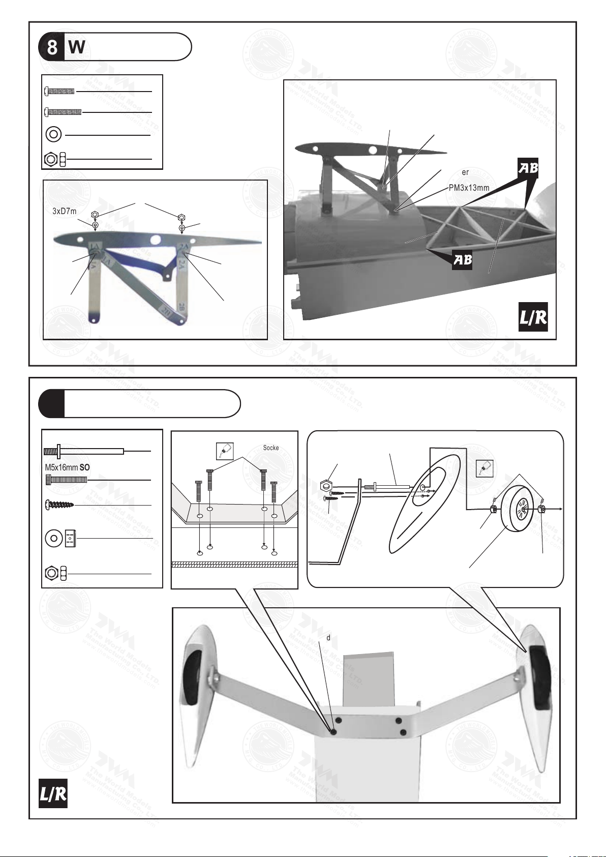
Wing Cabane
1 A
1 A
1 A
2 A
2 A
2B
2B
8
PM3x 13mm Screw
5
PM3x 16mm Screw
1
d3xD7mm Washer
12
M3 Nylon Inert Lock Nut
6
M3
Nylo n Inert L ock Nut
d3xD7 mm
Was her
d3xD7 mm
Was her
PM3x1 6mm
d3xD7 mm
Was her
d3xD7 mm
Was her
PM3x1 3mm
d3xD7 mm
Was her
M3 Nyl on Iner t Lock Nu t
d3xD7 mm
Was her
PM3x1 3mm
F18B
F18C
Main Landing Gear
9
Ø4x54mm Axle Shaft
M5x16mm SOCKET HEAD SCREW
PA3x12 mm Screw
4.1mm Collar
M8 Nylon Inert Lock Nut
2
M5x1 6m m So cke t He ad
Scre w
M8 Nyl on
Iner t Loc k Nut
Ø4x54mm
3mm Se t Scr ew
4
4
PA3x12 mm
4
4.1mm Collar
4.1mm Collar
2
M5x1 6mm
Sock et He ad Sc rew
Wheel Ø76mm
P.7
Page 9
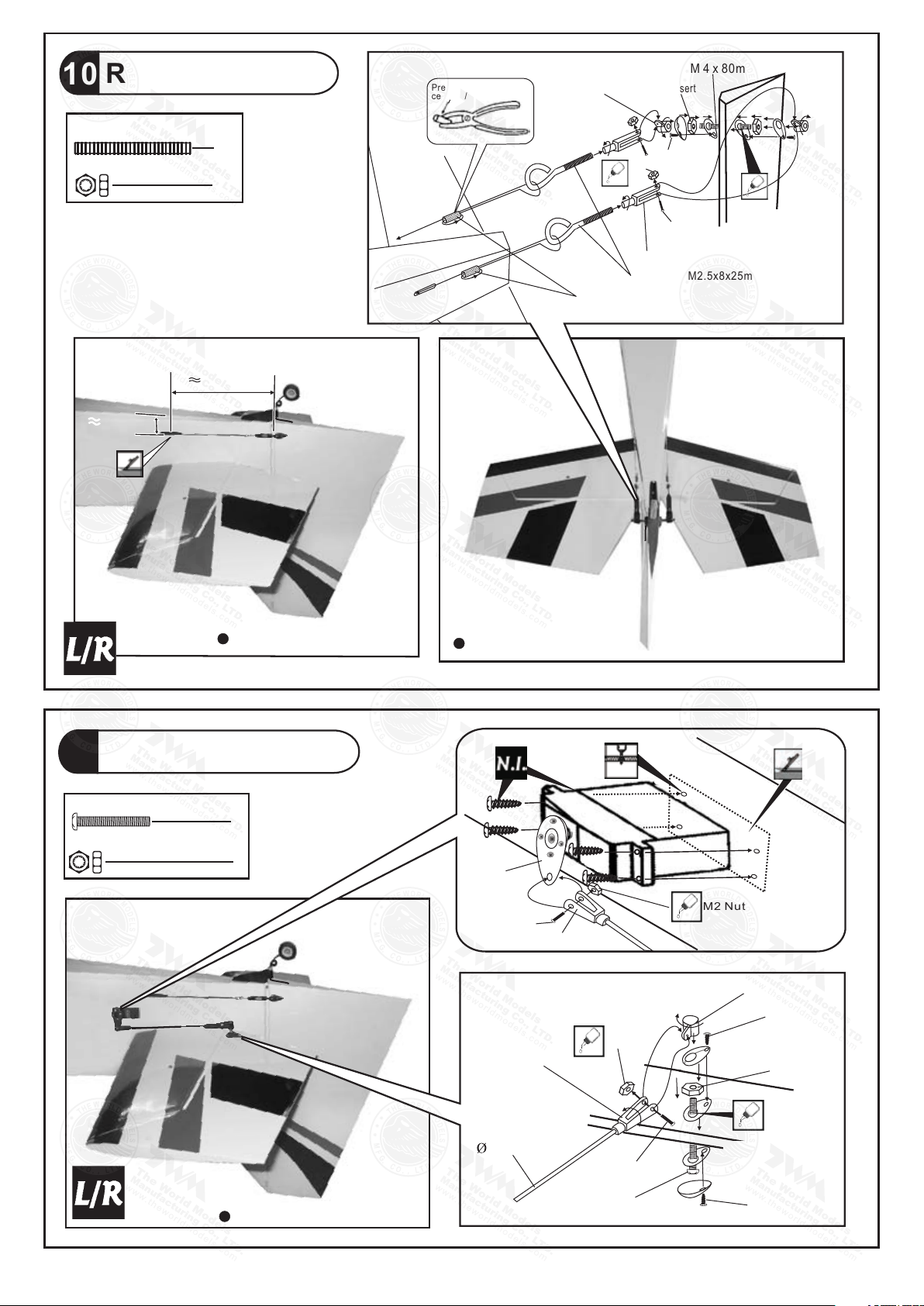
Rudder Pullwire
Eye Sc rew M 2. 5x8 x25mm
Copp er Tub e
10
M 4 x 80mm Screw
1
M4 Nylon Insert Lock Nut
2
165mm
28mm
Press d ow n th e
cente r 1/ 3 po rt io n
Heav y Du ty H or n
Brac ke t
M4 Nyl on In se rt
Lock N ut
PA1. 7x 8m m
M2 Nut
PM2x 8m m
Heav y Du ty
Clev is
M 4 x 80mm
Bottom View
Elevator Pushrod
11
PM 4 x 50mm Screw
2
M4 Nylon Insert Lo ck Nut
2
Bottom View
Bottom View
PL41 203 50
PM2x 8m m
Heav y Dut y Cle vis
Heavy D uty
Clevi s
1mm
M2 Nut
M2 Nut
Heav y Dut y Horn Br ack et
PA1.7x8 mm
M4 Nylon Insert
Lock Nut
7
Bottom View
Pushrod
2.5x145mm
P.8
PM2x 8mm
PM 4 x 50mm
3.7mm
PA1.7x8 mm
Page 10
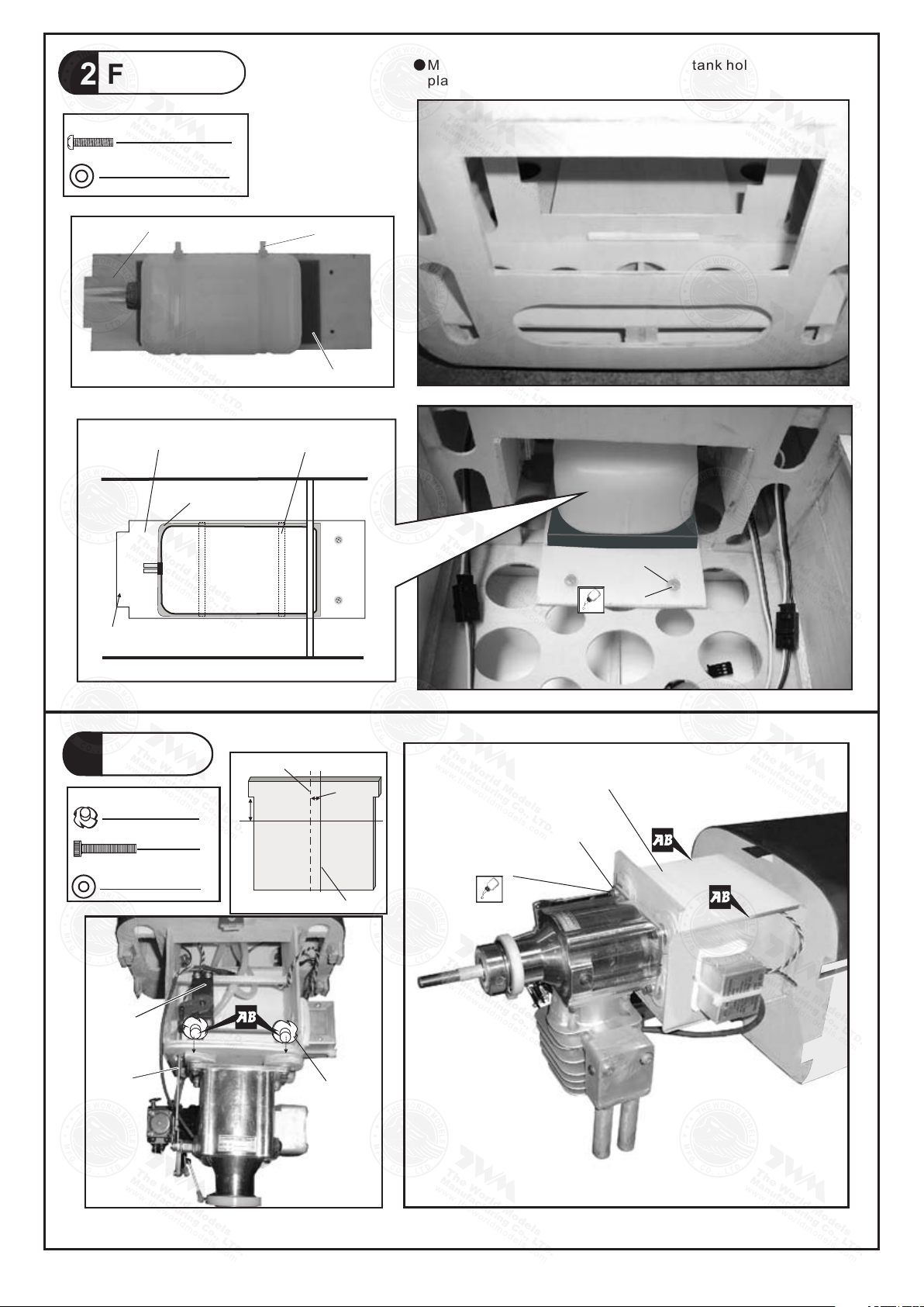
Fuel Tank
12
Make su re tha t tongue on f ront o f fuel tank h old do wn
plate s lide s into slot o f F2.
PM3x12mm Screw
d3xD7mm Washer
Plyw ood 3 x95 x28 1mm (F2A)
Plyw ood 3 x95 x28 1mm (F2A)
Plyw ood 3 x95 x28 1mm
Plyw ood 3 x95 x28 1mm (F2A)
Spon ge t o cu shi on
fuel t an k.
Fuel Ta nk
650c c
2
2
Cable Tie
Sponge
Cable Tie
F2
d3xD 7mm
Was her
PM3x 12m m
Tongue
Engine
13
M6 Blind Nut
M6x20mm SOCKET HEAD SCREW
d6xD15mm Washer
Thro tt le
Serv o
Cent er l in e of fi re wa ll
31. 8
mm
4
4
4
F9
4.8 mm
Engi ne t hr ust l in e
Plyw ood 3 x12 0x1 29.5mm (F8 A)
d6xD 15m m Wa sher
M6x2 0mm s ock et he ad screw
Thro tt le P ush ro d
M6 Bli nd Nu t
P.9
Page 11
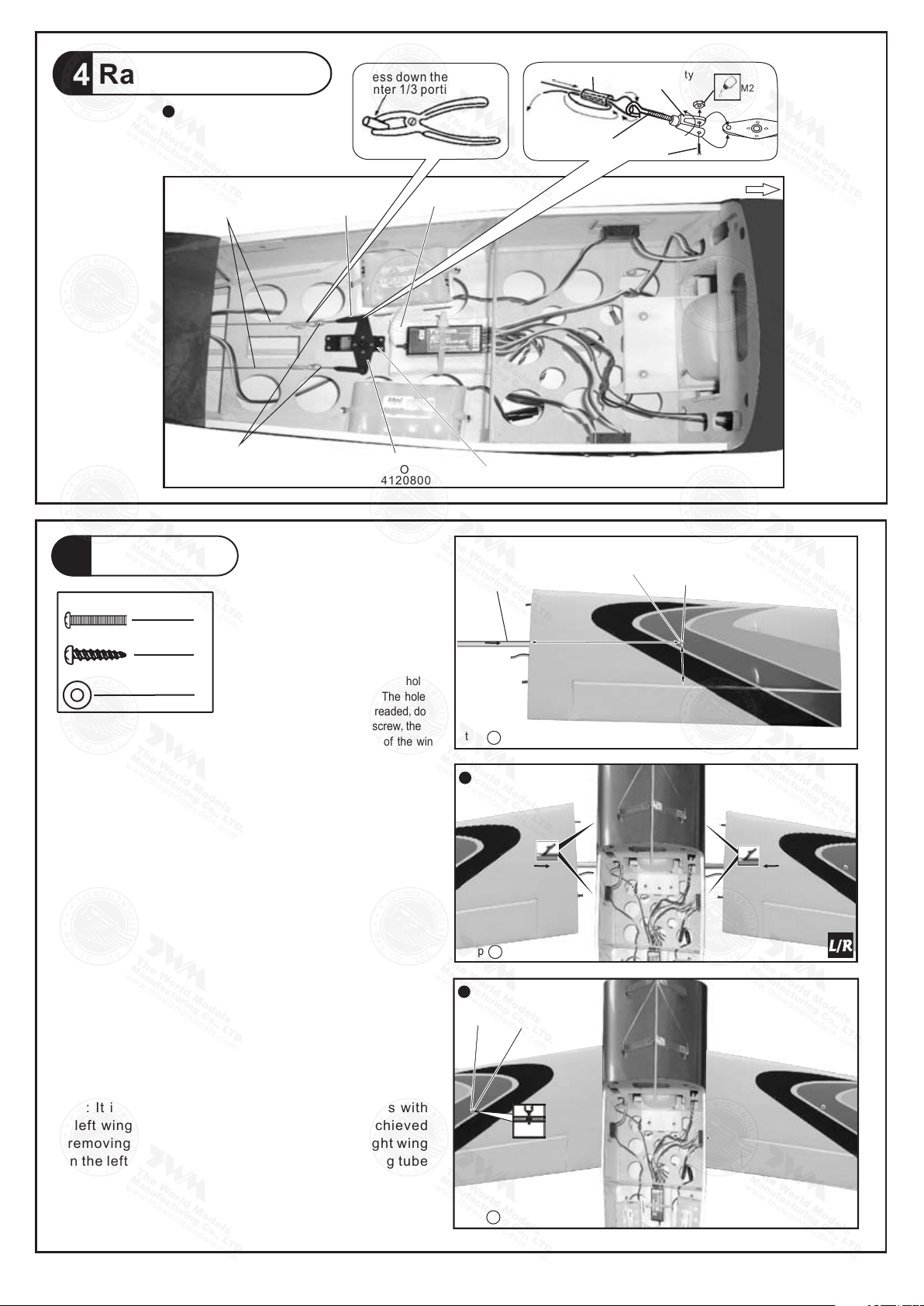
Radio Equiment
Copp er Tu be
PM2x8mm
Heav y Du ty
Clev is
Eye Screw
M2 Nut
14
In s t al l a n d a r r an g e
th e s erv o a s s h o w n
in t h e di a g ra m .
Press d own t he
cente r 1/3 p ort ion
15
(Lower)
Main Wing
3
PM3x16mm Screw
PA3x16 mm Screw
d3 x D7mm Washer
Rudder P ullwi re
Ø1x800m m
Eye Scre w
M2.5x8 x25mm
Step1.Insert aluminum wing tube
(Ø16x806mm)with the pre-drilled
hole end into the right wing(lower).
Align the lines marked at the wing
root and wing tube,then apply the
1
PM3X16mm machine screw through
the pre drilled hole on top of the
-
wing.(please confirm the alignment
1
of the hole by putting a 2.5mm diameter
rod through the pre-drilled wing hole
2
before applying the screw) The hole
on the wing tube is pre-threaded,do
not over tighten the PM3 screw,the
set up is for future removal of the wing.
Heavy D uty
Clevi s
HEAVY DUTY
SERVO HO RN
PL41 208 00
Spong e
Rudder S ervo
Wing Tu be
Ø16x8 06m m
Step
1
d3 x D7m m
Was her
≈295m m
≈10
Front
PM3x 16m m
2mm
Main W ing (Lo wer )
Step 2. Ins tal l the r igh t w ing to the fusel age by ins ert ing th e wi ng
tube (now atta che d to the r igh t win g) th rou gh the f uselage, then
inst all t he le ft wi ng.
St e p 3. M a k e s u r e th e w in g s ar e r est i ng a g a in s t th e
fu s e la g e ti gh t l y. Lo c a te th e pr e -d r i ll e d 2m m ho l e
at to p o f l e f t w in g , a n d d ri l l a lon g w i th 2mm d r i ll bi t
un t i l i t pa s ses thr o ugh the w i n g t u b e . A pp l y th e
PA 3 x 16 m m s el f - t ap p i n g s c r e w.
Note : It is recomme nded that the wing tube s tays with
the left w ing. Remov al o f th e wi ngs could be achi eved
by r emoving th e righ t wing machine screw, the ri ght wing
then the le ft win g w ith wing tube . If remov al of wing t ube
from left wing is also required, it is recommende d that
inste ad of app lying self-ta ppin g scre w in step 3, y ou pre tap wit h M3 thr ead cutte r and ap ply M3 mach ine sc rew.
Top Vi ew
Step
2
Top Vi ew
PA3x16m m
Step
3
d3 x D7m m
Was her
2.5m m
Left
Righ t
P.10
Page 12
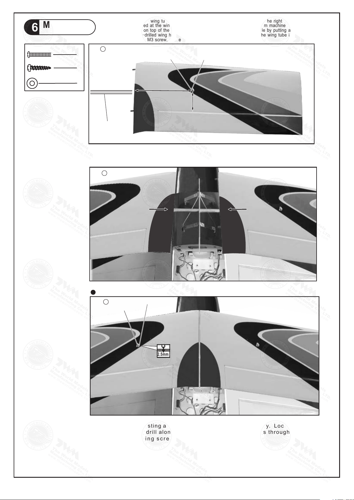
16
(Upper)
Main Wing
3
PM3x16mm Screw
PA3x16 mm Screw
d3 x D7mm Washer
Step1.Insert aluminum wing tube (Ø16x645mm)with the pre-drilled hole end into the right wing(upper).
Align the lines marked at the wing root and wing tube,then apply the PM3X16mm machine screw through
the pre-drilled hole on top of the wing.(please confirm the alignment of the hole by putting a 2.5mm diameter
rod through the pre-drilled wing hole before applying the screw) The hole on the wing tube is pre-threaded,do
not over tighten the PM3 screw, the set up is for future removal of the wing.
Step
1
1
d3 x D7mm Washer
PM3x16mm
1
2
Wing Tube
Ø16x645mm
Step 2. Inst all the rig ht w ing to t he c ent er w ing cabane by insert ing the win g tu be ( now att ached to the
righ t win g) th rou gh the caban e, th en in sta ll the left wi ng.
Step
2
≈305mm
≈92mm
Top Vi ew
Step
3
Left
St e p 3 . Ma k e su r e th e w ing s a re r e sti n g ag a i ns t t h e c e n te r w i ng c a ba n e t ig h t ly. L o c at e t he p r e -d r i ll e d
2m m h o le a t t op of l e ft wi n g, an d d ri l l alo n g wit h 2 mm dr i ll b i t u nt i l it pa s ses t h rou g h the w i n g t u b e .
A p p ly t he P A 3x 1 6 m m s el f - t a p pi n g s c r e w .
Note : It is recomme nded that the w ing tube stays with the le ft w ing. Remo val of t he wing s co uld be achi eved
by removi ng t he r ight wing m achi ne s crew, the right wing the n th e left wing wit h wi ng t ube. If remov al o f wi ng
tube from left wing is al so require d, it is rec ommende d t hat in stead of applyin g s elf-tap ping screw in s tep 3,
you pre -tap w ith M3 thre ad cut ter and app ly M3 ma chine scr ew.
d3 x D7mm Was her
PA3x1 6mm
2.5m m
Right
P.11
Page 13
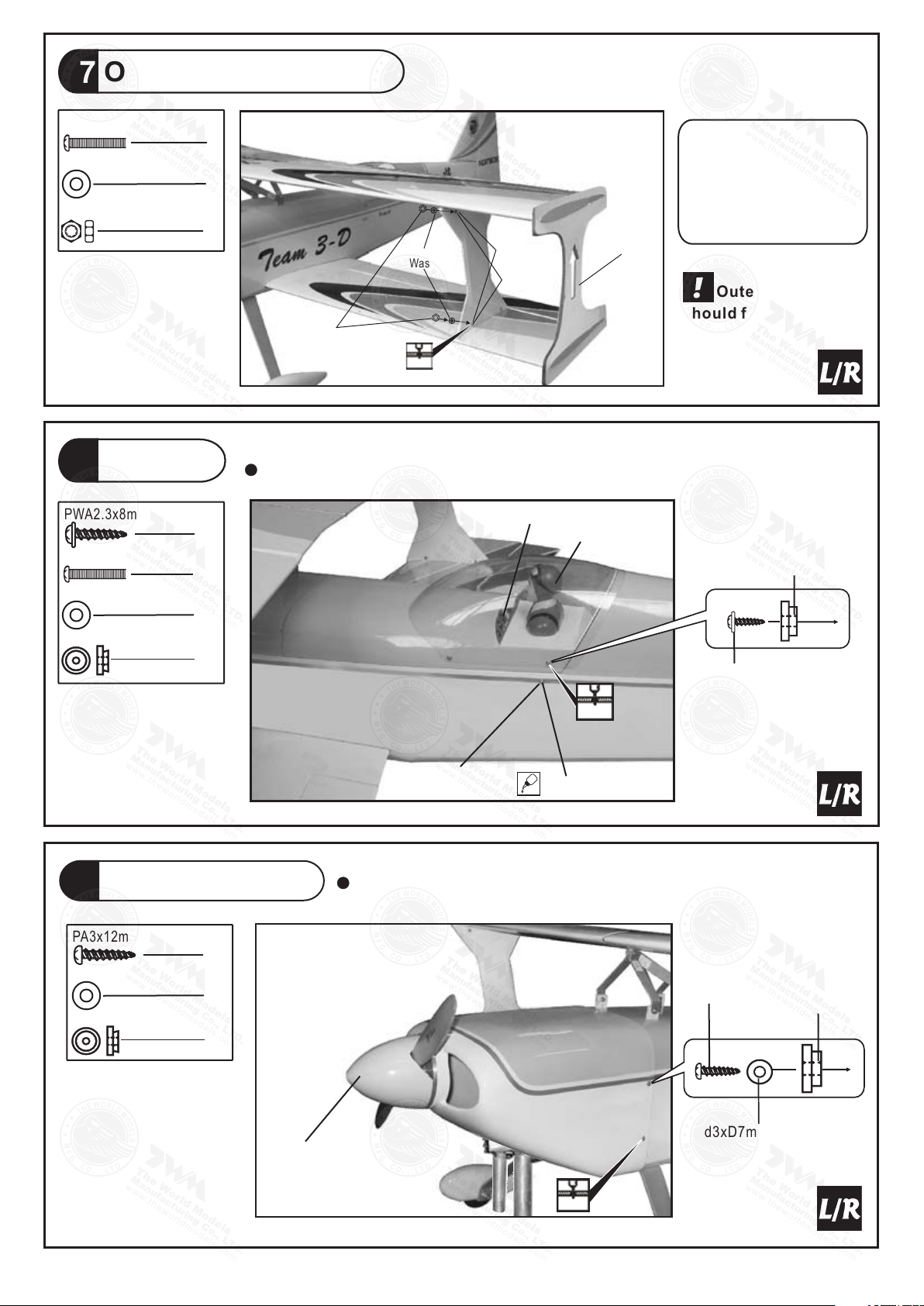
Outer Wing Cabanes
17
PM3x18mm Screw
d3 x D7mm Washer
16
M3 Nylon Inse rt Lock Nut
Canopy
18
PWA2.3x8m m Screw
4
PM3x16mm Screw
2
d3 x D7mm Washer
2
d1.5 x D6.5 mm
Silicon Grommet
4
8
8
d3 x D7m m
Was her
M3 Nyl on In ser t
Lock N ut
3mm
d3 x D7m m
Was he r
PM3x 18 mm
Plyw oo d
3x33 0x 388 mm
With the wing incidence
angle template still in place,
position the side cabanes,
mark and drill the side
cabane mounts and fasten
with PM3x18mm screw and
nut.
Outer win g cabane
should fi t to the out side
of outer wing caban e
mounts.
First insert the grommet to the canopy then apply screw.
Decals
Pilot
d1.5xD6.5mm
Silicon Grommet
PWA 2.3 x8m m
Cowling & Spinner
3
19
PA3x12 mm Screw
5
d3 x D7mm Washer
5
d2.5 x D8.5 mm
Silicon Grommet
5
Spinner
Ø89mm
1.5mm
d3 x D7mm
Washer
PM3x16mm
First insert the grommet to the cowling then apply screw.
PA3x12 mm
d3xD7mm Was her
d2.5xD8.5mm
Silicon Gromme t
P.12
1.5m m
Page 14
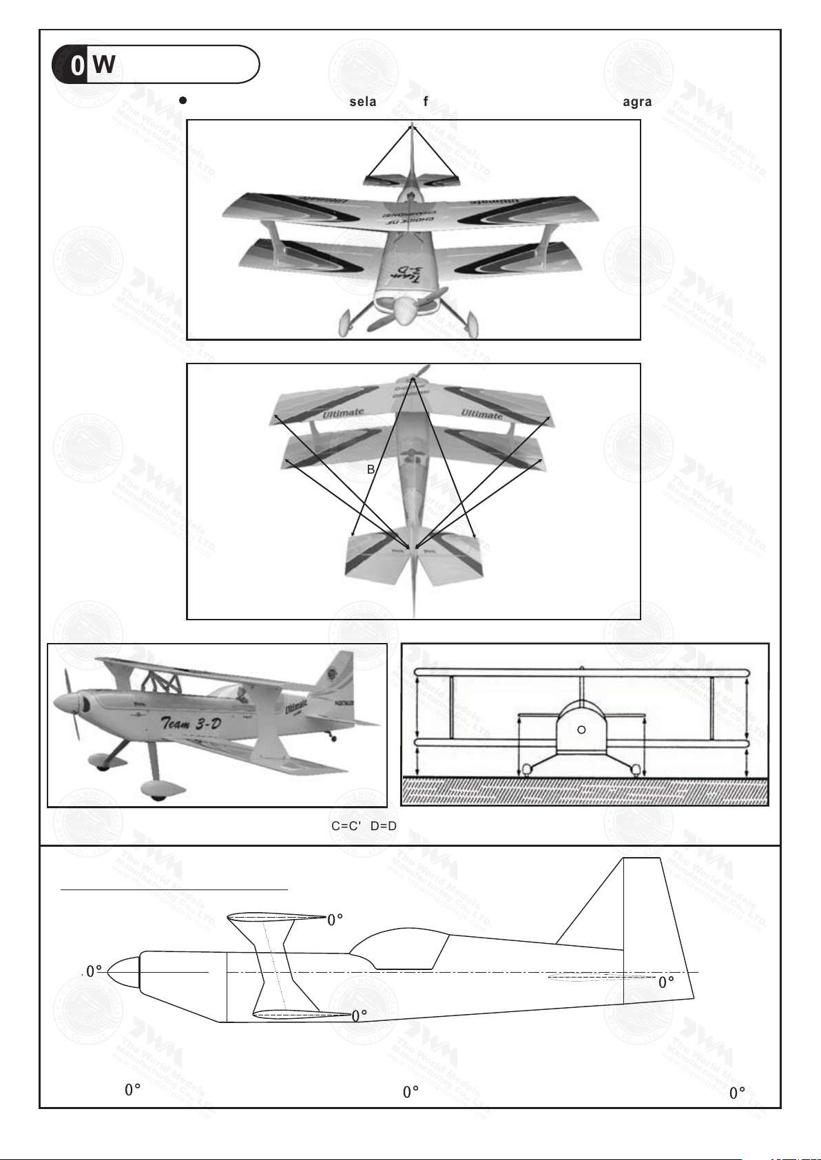
Wing Setting
B
B'
C C'
D
D'
A A '
20
Adjust the wing and fusel age con figuration as shown in the diag rams.
A=A' B =B'
A 7 2 S 1 27 % UL TI MA TE
ENGINE
DOWN THRUST
ANGLE
C=C'
MAIN WING
INCIDENCE
ANGLE
E E'
F
D=D' E=E ' F=F'
G G'
G=G'
STABILIZER
INCIDENCE
ANGLE
F'
P.13
Page 15
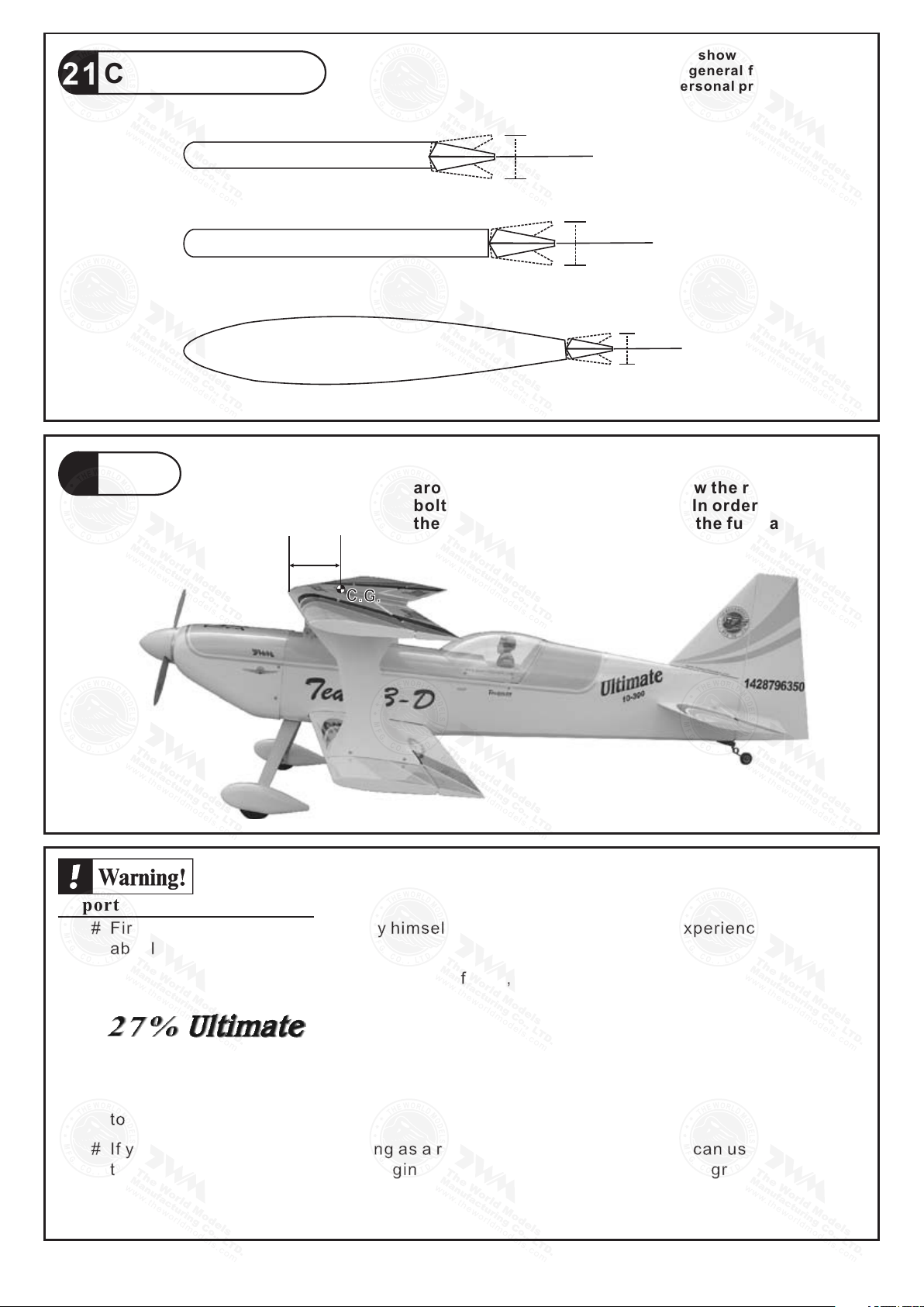
Control Throws
21
C.G.
22
Elevator
Rudder
Ailerons
135mm
5.3 in.
Adjus t the co ntrol thr ows as s hown in the d iagr am.
These throw s are goo d for genera l f lying. You can
adjus t acco rding to yo ur per sonal pre fere nce.
30mm
30mm
70mm
70mm
25mm
25mm
The ideal C.G. position is at center of top wing tube.
You can check the C.G. by hanging the plane with wire
around the top wing tube. Unscrew the right wing
bolt will leave a gap for the wire. In order to obtain
the C.G. specified, add weight to the fuselage or
move the battery position. Check the C.G. before
flying.
Important Safety Precautions
# First time flyer should never fly by himself / herself. Assistance from experienced flyer is
absolutely necessary.
# Pre-flight adjustment must be done before flying, it is very dangerous to fly a badly
pre-adjusted aircraft.
# is specially designed to be powered by 50 gasoline engine,
using a more powerful engine does not mean better performance. In fact, over powered
engine may cause severe damage and injuries.
# Make sure the air field is spacious, never fly the plane too close to people and never get
too close to a running propeller.
# If you find wrinkles on the covering as a result of weather changes, you can use hot iron
to remove the wrinkles. Please begin with lower temperature setting and gradually raise
the temperature until the wrinkles are gone. Too hot an iron may damage the covering.
# Check and re-tighten up all factory assembled screws, use thread locker if applicable.
A172S1PO11800 906
cc
P.14
Page 16
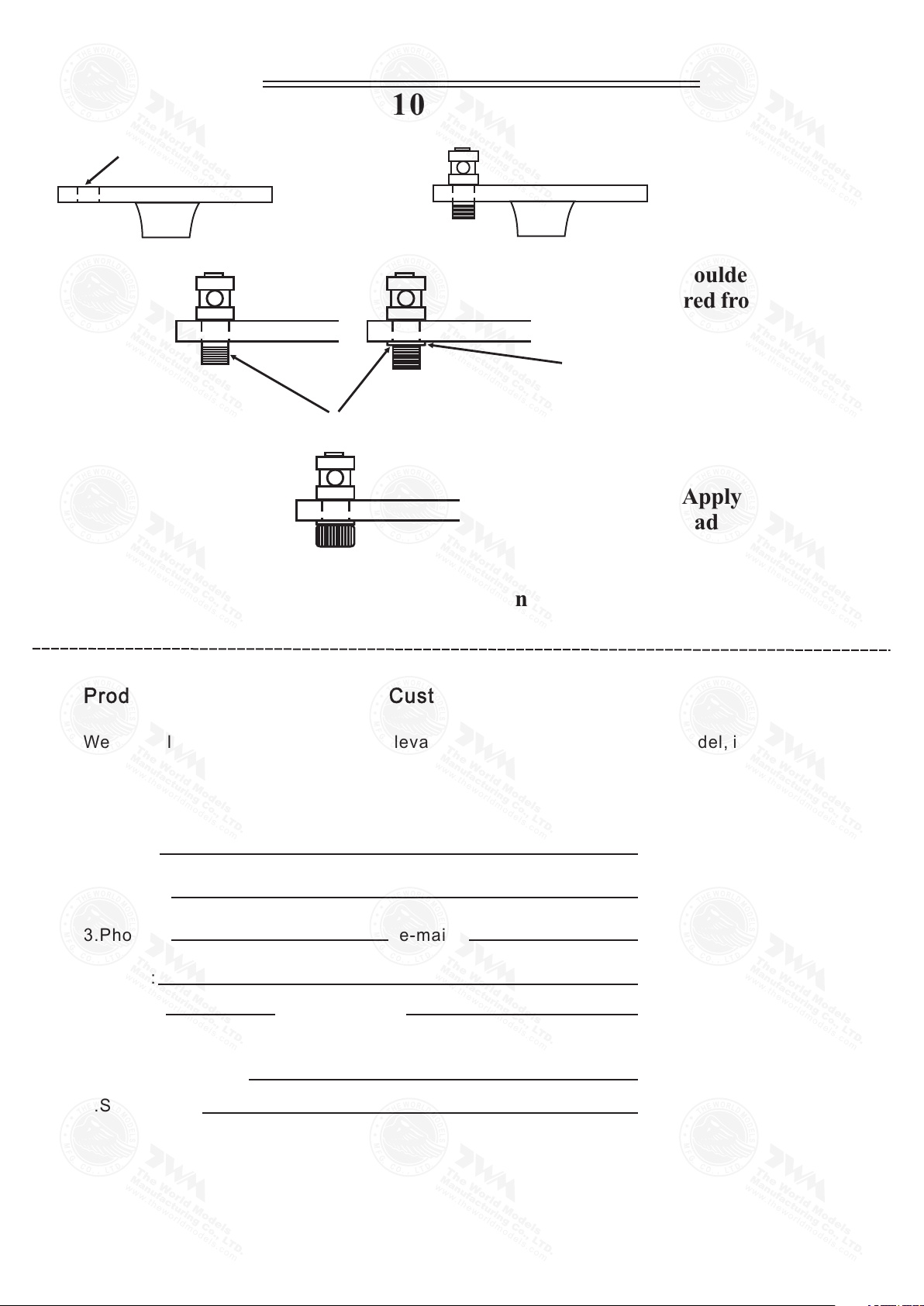
LINKAGE CONNECTOR
HW7111030 & HW7111060
Drill 2mm hole at servo horn.
Sh oul d er
Insert linkage connector
into servo horn.
Make sure shoulder of
screw is cleared from
servo horn.
Add washer to reduce
play if necessary.
Tighten up the round nut
against the shoulder. Apply
CA or permanent thread
locker.
After fastening the round nut, make sure that
the linkage connector can rotate freely.
Product Registration Form (US Customers)
We would like to share with you any relevant information regarding your model, including
product news and free upgrade parts when applicable. Please fill in the following and send to
Air Borne Models,4749-K, Bennett Drive, Livermore, CA 94551 USA.
1.Name:
2.Address:
3.Phone #: e-mail:
4.Model:
Wing QC# Fuselage QC#
(QC numbers are stamped on wing and fuselage)
5.Date of Purchase:
6.Store Name:
Please call AirBorne Models at 925 371 0922 for any assistance in filling this form.
Thank you very much for purchasing our product.
A172S1PO11800 906
 Loading...