

Page 1
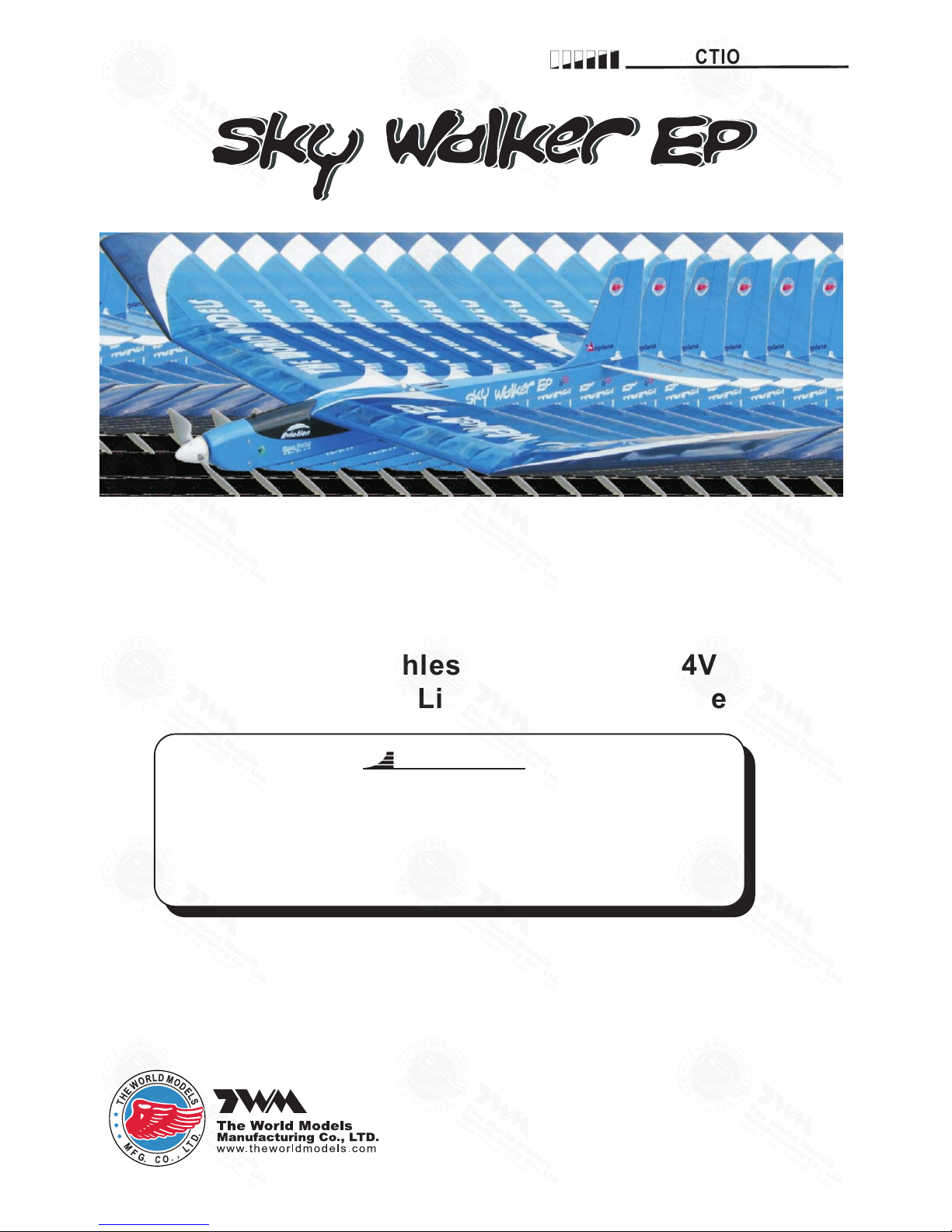
Wing Span
63.0 in / 1600 mm
Wing Area
Flying Weight
Fuselage Length
17 480 oz / g
420 sq in / 27 sq dm
3 in / 8 mm3 35
Warning ! This model is not a toy.
It is designed for maximum performance. Please seek advice if one is not familiar with this kind
of electric powered pre cision model. Operating this model without prior preparation may cause
injuries. Remember, safety is the most important thing. Always keep this instruction manual at
hand for quick reference.
*Specifications are subject to change without noti ce.*
INSTRUCTION MANUAL
Specifications
Requires : 3- channel radio w/ 2 micro servos,
Outrunner Motor KM0283010
w/ Propeller Adaptor HW23
40100
15A Brushless ESC,2 cells 7.4V
1000 mAh Li-Po battery & charger.
FACTORY PRE-FABRICATED
ALMOST-READY-TO-FLY (ARF) SERIES
MADE IN CHINA
E182 NXM PO259 61107
Page 2

P.1
INDEX
P. 3-9
BEFORE YOU BEGIN
PARTS LIST
ASSEMBLY
SAFETY PRECAUTIONS
P. 1
P. 2
P.9
BEFORE YOU BEGIN
1
2
3
3mm
Do not overlook this symbol!
Cut off shaded portion.
Peel off shaded portion
covering film.
Pay close attention here!
Pierce the shaded portion
covering film.
Must be purchased separately!
Drill holes with the specified
diameter (here: 3mm).
Ensure smooth non-binding
movement while assembling.
Apply instant glue
(C.A.glue, super glue.)
Assemble left and right
sides the same way.
Apply epoxy glue.
Apply thread locker
Warning!
E182 NXM PO259 61107
Page 3

P.2
Parts list
1. MAIN WING -- 1 pair.
WING JOINER Ø4.5 x 1 61 mm -- 1 pc.
2. FUSELAGE -- 1 pc.
STABIL IZER & ELEVATOR -- 1 set
3. VERTICAL FIN & RUDDER - - 1 set
4. PUSHROD Ø1.4X 486 mm
w/ Threads(For E levator ) – 1 pc.
SCREW PB2X8 mm -- 2 pcs
HORN PL4113102 -- 1 set
CLEVIS PL411210 5 – 1 pc.
FUEL TUBE d2XD4X4 mm -- 1 pc.
5. PUSHROD Ø1.4 x 43 2 mm
w/ Threads(For R udder) -- 1 pc.
SCREW PB2X10 mm -- 2 pcs
HORN PL4113102 -- 1 set
CLEVIS PL411310 2 – 1 pc.
FUEL TUBE d2XD4X4 mm -- 1 pc.
6. SOCKET HEAD SCR EW M3x6mm -- 4 pcs
WASHER d3xD7mm -- 4 pcs
FOLDING RPOPEL LER SET (10X6)P L6314020 -- 1se t
COWLING -- 1 pc.
SCREW PWA2X8 mm -- 4pcs
SPINNER Ø36 mm -- 1 se t
7. SPONGE 10X50X 150 mm -- 2 pc.
STRAPER PL4112106– 2 pcs
FUEL TUBE d2XD4X4 mm -- 2 pcs
DOUBLE-SIDED TAPE 30X35 mm -- 1 pc.
BATTERY TIE 200mm -- 1 pc.
8. PVC PLATE 0. 8X20X42 mm( Wing Protection) -- 1 pc .
SCREW PM2. 5X 16 mm -- 2 pcs
WASHER d2. 6XD9 mm -- 2 pcs
9. CANOPY -- 1 set
10. DECALS:E182NXMDEC -- 1 set
COVERING:
YELLOW COLOR SCHEME:
LIGHTEX SGX 000 TRANSPARENT
LIGHTEX SGX 030 TRANSPARENT YELLOW
LIGHTEX SGX 330 CADMIUM YELLOW
LIGHTEX SGX 100 WHITE
LIGHTEX SGX 201 BLACK
LIGHTEX SGX 312 BRIGHT RED
BLUE COLOR SCHEME:
LIGHTEX SGX 000 TRANSPARENT
LIGHTEX SGX 050 TRANSPARENT BLUE
LIGHTEX SGX 251 SKY BLUE
LIGHTEX SGX 100 WHITE
LIGHTEX SGX 201 BLACK
LIGHTEX SGX 350 CORSAIR BLUE
E182 NXM PO259 61107
Page 4

Completed
Wing Joiner
Ø4.5 x 161mm
Main Wing
P.3
1
Stabilizer & Elevator
2
Apply instant type CA glue to both sides of each hinge.
Completed
(Sta bi li ze r)
(Mai n Wi ng )
A
A'
B B'
B=B '
Temp o r a r y i n s t a ll t h e ma i n wing , adju s t
leve l i n g of t h e s t a b i lize r to m a k e i t a s
para l l e l to t h e m a i n wi n g as p o s sibl e .
*Also refe r to st ep 10 W ing S ett ing
Bottom View
E182 NXM PO259 61107
Page 5

P.4
Vertical Fin / Rudder
3
Peel off shaded Portion
covering film.
Ap pl y i ns ta nt ty pe CA g lu e t o bo th si de s o f e ac h h in ge .
Completed
E182 NXM PO259 61107
Page 6
P.5
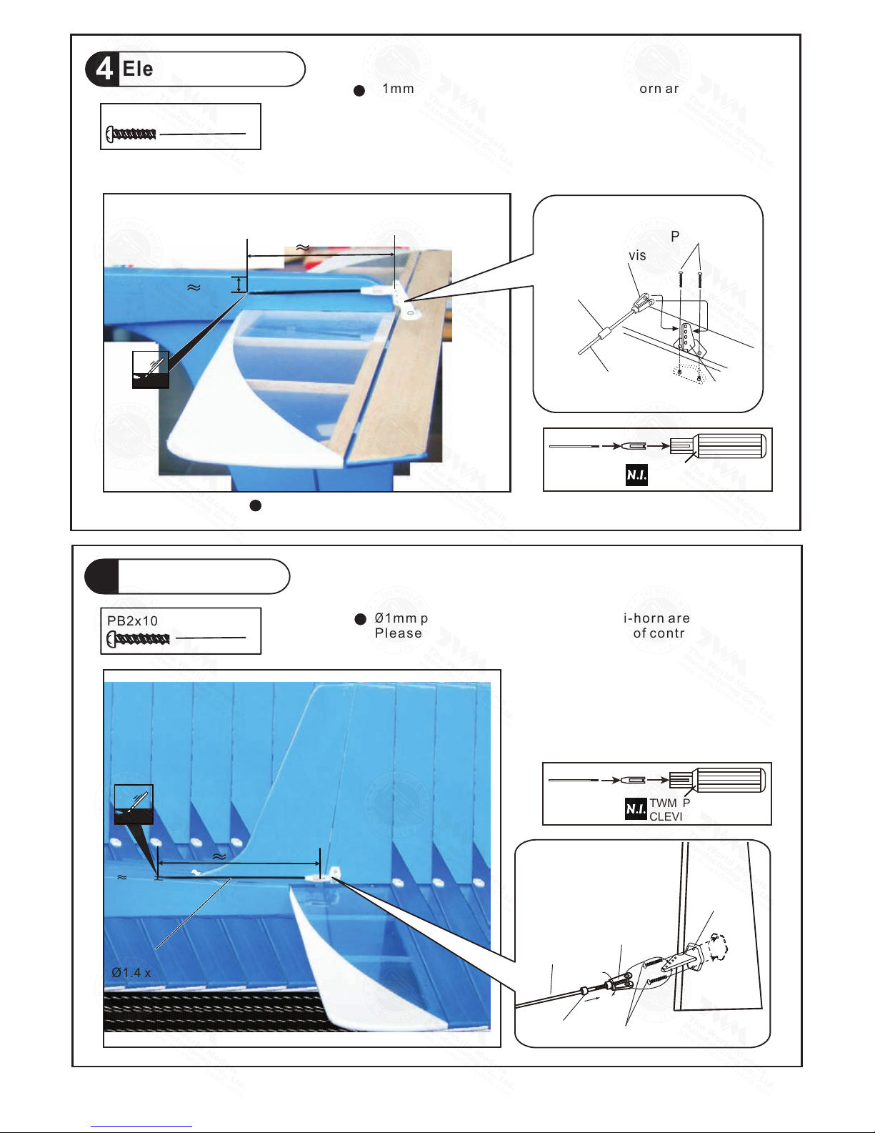
Elevator Pushrod
4
7
PB2x10 mm Screw
2
7
Rudder Pushrod
5
5mm
14
8mm
78mm
9mm
Pushro d
Ø1.4 x 445mm
Bottom View
PB2x8m m Screw
2
PB2x10 mm
Clevis
Horn
Pushro d
Ø1.4x432mm
Fuel Tube
d2xD4x4m m
Horn
Pushrod
1.4x486mm
Fuel Tube
d2xD4x4mm
Clevis
PB2x8mm
TWM PL8210010
CLEVIS WRENCH
TWM PL8210010
CLEVIS WRENCH
Ø1mm pil o t ho l es fo r W o rl d M ode l s tr i - ho r n are p r e- d ril l ed.
Ple a se l ook for pin - hol e ma r ks a t u n der sid e of con t rol
sur f ace s .
Ø1mm pil o t ho l es fo r W o rl d M ode l s tr i - ho r n are p r e- d ril l ed.
Ple a se l ook for pin - hol e ma r ks a t s i de o f c o ntr o l s u rfa c es .
E182 NXM PO259 61107
Page 7

P.6
6
Motor / Cowling Setting
PWA2x8mm Screw
4
4
M x mm Sock Head Screw3 6
PM2x12mm Screw
4
2
PA2.6x8mm Screw
d3xD7mm Washer
4
5
6
7
4
3
Spinn er
PM2x1 2mm
PM2x1 2mm
PA2.6x8 mm
PWA 2x8mm
Don't over - tighte n the P M2 screws ,
let the prop eller blades a lign
thems elv es when spi nni ng.
M5 Nut
TWM
KP0011310
SolderSolder
2
M3x6m m
Socke t Hea d Screw
d3xD7 mm
Was her
Don't ov er-tighte n the
PM3 scre ws, too much
stress o n the screws
could sp lit the firew all.
TWM HW 31114 00
PROP EL LE R AD APTO R WRENC H
Outrunner Motor 28/ 30
KM0283010
Propeller Adaptor
(d3xD5) HW2340100
Optional Parts
E182 NXM PO259 61107
Page 8

P.7
C a n o py
9
Radio Equipment
Rudder Pushrod
Install and arrange the servo as shown in the diagram.
7
Main Wing
8
d2.6xD 9mm Washer
PM2.5x 16mm Screw
2
2
PM2.5 x 16mm
Win g Prote ct io n
0.8 x 2 5 x 61mm
d2. 5 x D8mm
PM2 .5 x 16mm
2.5m m
Peel off shaded portion covering film.
Bottom View
d2.6 x D9mm
Completed
Rudder Servo
Straper
Sponge
Fuel Tube
D2XD4X4mm
Elevator Pushrod
Brushless ESC
Elevator Servo
Battery
Double-Sided Tape
Battery Tie
Front
E182 NXM PO259 61107
Page 9

P.8
Wing Setting
10
Adjust the wing and fuselage configuration as shown in the diagrams.
A=A' B=B' C=C'
A A'
B
B'
C'C
Adjust the control throws as shown in the
diagram. These throws are good for general
flying. You can adjust according to your
personal preference.
Elevator
Rudder
25mm
25mm
10mm
10mm
Control Throws
11
E182 NXM PO259 61107
Page 10

6.Store Name:
5.Date of Purchase:
Wing QC# Fuselage QC#
(QC numbers are stamped on wing and fuselage)
4.Model:
3.Phone #: e-mail:
2.Address:
1.Name:
The ideal C.G. position is 53mm (2.1 in.) ehind the leading edge
measured at where the wing meets the fuselage. In order to obtain
the C.G. specified, add weight to the fuselage or move the battery
position. Check the C.G. Before flying.
b
53mm
C.G .
2.1 in.
Important Safety Precautions
Warning!
P.9
C.G.
12
#First time flyer should n ever fly by himself/her self. Assistance from ex perienced flyer is
absolutely necessary.
#Pre-fl ight adjustme nt must be done before flyi ng, it is very dangerous to fly a badly
pre-adj usted aircraft.
# is specially des igned to b e powered by KM0283010 Outru nner Motor.
to higher speed which will damage th e wing structur e and airf rame, and will no t be cover ed
by manufacturer ’s warranty.
#Make sur e the air field is sp acious , never fly the pla ne too close to people and ne ver get
too close to a running propeller.
#If you find wrinkles on the c overing as a result of weat her changes, you can use ho t iron
to remove the wrinkles. Pl ease beg in with lower tem peratu re setting and gr aduall y raise
the temperature until th e wrinkles are gone. Too hot an iron may damage t he covering.
#Check an d re-tighten up all factory assembled screws, us e thread locker i f applic able.
with 2-ce ll 7.4V Li-Po battery operation. Using m ore powe rful system wil l push the model
Product Registration Form (US Customers)
We would like to share with you any relevant information regarding your model, including
product news and free upgrade parts when applicable. Please fill in the following and send to
Please call AirBorne Models at 925 371 0922 for any assistance in filling this form.
Thank you very much for purchasing our product.
Air orne Models, 4749-K, Bennett Drive, Livermore, CA 94551 USAB .
http :// ww w.th ewo rldmo del s.com /pa ra/in str uctio n/i nstru cti onMan ual s.p hp
E182 NXM PO259 61107
Page 11

Large C lev is
Small C lev is
Pl8210 010
E182 NXM PO259 61107
Page 12

The World Models
Manufacturing Co., LTD.
www. t h e w orldm o d e l s.c o m
Warbirds
Scale
Sports
Trainer
Ducted Fan
Pattern
Funfly
Electric
Glider
Boat
Accessories
Covering
(Lightex / Toughlon)
E182 NXM PO259 61107
 Loading...