


* Specifications are subject to change without notice. *
Requires: 50cc gasoline engine,
4-channel radio w/ 6 high torque servos.
INSTRUCTION MANUAL
Warning! This model is not a toy.
It is designed for maximum performance. Please seek advice if one is not familiar with this kind
of engine powered precision model. Operating this model without prior preparation may cause
injuries. Remember, safety is the most important thing. Always keep this instruction manual at
hand for quick reference.
Wing Span 118 in / 3000 mm
Wing Area 1990 sq in / 128 sq dm
Flying Weight 18.5 lbs / 8450 g
Fuselage Length 75 in / 1900 mm
Specifications
(
A037
)
FACTORY PRE-FABRICATED
ALMOST-READY-TO-FLY (ARF) SERIES
MADE IN CHINA
The World Models
Manufacturing Co., LTD.
www.theworldmodels.com
A037PO31141601

P.1
INDEX
Read through the manual before you begin, so you will have an overall idea of what to do.
BEFORE YOU BEGIN
BEFORE YOU BEGIN
PARTS LIST
ASSEMBLY
SAFETY PRECAUTIONS
P.1
P.2
P.3-P.13
P.13
Check all parts. If you find any defective or missing parts contact your local dealer. Please
DRY FIT and check for defects for all parts that will require CA or Epoxy for final assembly.
Any parts you find to be defective after the gluing process may be difficult to remove for
warranty replacement. The manufacturer will replace any defective parts, but will not extend
to the parts that are good before gluing to defective parts during assembly. Warranty will
not cover any parts modified by customer.
Symbols used throughout this instruction manual comprise of the following :-
1
2
3
Cut off shaded portion.
Ensure smooth non-binding
movement while assembling.
Apply instant glue
(C.A.glue, super glue.)
Assemble left and right
sides the same way.
Peel off shaded portion
covering film.
Pay close attention here!
Apply epoxy glue.
Must be purchased separately !
Drill holes with the specified
diameter (here: 3mm).
Pierce the shaded portion
covering film.
3mm
Do not overlook this symbol !
Warning!
Apply thread locker
A037PO31141601

P.2
Parts List
1. MAIN WING -- 1 pair
2. SERVO MOUNTING PANEL (For Aileron) PL5310010 -- 1 pair
HEAVY DUTY CLEVIS PL4112200 -- 4 sets
SOCKET HEAD SCREW M4x60mm -- 2 pcs
SCREW PWA2.3x8mm -- 8 pcs
M4 NYLON INSERT LOCK NUT -- 2 pcs
HEAVY DUTY HORN BRACKET PL4112400 -- 2 sets
HEAVY DUTY SERVO HORN PL4120250 -- 2 sets
PUSHROD M3xD5x113mm w/ Threads (For Aileron) -- 2 pcs
SWIVEL CLEVIS HORN FAIRING PL4610010 -- 2 sets
3. SOCKET HEAD SCREW M3x18mm -- 8 pcs
SOCKET HEAD SCREW M4x18mm -- 4 pcs
WIRE BRACKET PL5330030Y -- 8 pcs
MAIN WING STRUTS -- 1 pair
WING STRUT WIRE D3mm -- 2 pcs
M3 NYLON INSERT LOCK NUT -- 4 pcs
WASHER d3xD7mm -- 12 pcs
WASHER d4.5xD9mm -- 4 pcs
4. FUSELAGE -- 1 pc.
COVERING 30x550mm -- 1 pc.
5. STABILIZER & ELEVATOR -- 1 set
SCREW PWM2.5x12mm -- 2 pcs
STABILIZER WIRE Ø4x170mm -- 2 pcs
6. VERTICAL FIN & RUDDER -- 1 set
7. TAIL GEAR ASSEMELY (PL3410033) --1 set
COPPER PLATE (For Stays on Tail Fueslage Bottom) 1.5x12x60mm -- 1 pc.
SCREW PA3x18mm -- 3 pcs
SCREW PWA2.5x12mm -- 2 pcs
SPRING Ø5x50mm -- 2 pcs
8. MAIN LANDING GEAR -- 1 set
SCREW HM4x20mm -- 2 pcs
SCREW PA3x18mm -- 12 pcs
SCREW PA4x20mm -- 2 pcs
WASHER d4xD9mm -- 4 pcs
MOUNTING PLATE 12x20mm PL4114020 -- 6 pcs
ALUMINUM PLATE 3mm -- 2 pcs
9. LARGE SCALE TREADED INFLATABLE WHEELS Ø118mm -- 2 sets
SCREW PA1.7x8mm -- 6 pcs
SCREW PM3x12mm -- 8 pcs
WASHER d3xD7mm -- 16 pcs
M3 NUT -- 8 pcs
COLLAR Ø5.1mm w/ set screw -- 4 sets
WIRE BRACKET PL5330050Y -- 8 pcs
PLYWOOD 2x178x186.4mm (Main Langing Gear Cover) --1 pair
10. BLIND NUT M5 -- 4 pcs
WASHER d5xD12mm -- 4 pcs
SOCKET HEAD SCREW M5x50mm -- 4 pcs
THROTTLE PUSHROD Ø1.8x430mm -- 1 pc.
PLASTIC TUBE d2.5xD4x300mm -- 1 pc.
11. COWLING -- 1 pc.
TRANSPARENT 3D TEMPLATE -- 1 pc.
SCREW PA3x12mm -- 4 pcs
WASHER d3xD7mm -- 4 pcs
SILICON GROMMET d2.5xD8.5mm -- 4 pcs
DUMMY ENGINE COVER -- 1 pair
12. FUEL TANK 800cc PL1111810G -- 1 set
CABLE TIE 1.5x8x500mm -- 1 pc.
DOUBLE-SIDED TAPE 40x160mm -- 1 pc.
13. PUSHROD M3xD5x170mm w/ Threads (For Elevator) -- 2 pcs
SOCKET HEAD SCREW M4x50mm -- 2 pcs
M4 NYLON INSERT LOCK NUT -- 2 pcs
SWIVEL CLEVIS HORN FAIRING PL4610010 -- 2 sets
HEAVY DUTY HORN BRACKET PL4112400 -- 2 sets
HEAVY DUTY SERVO HORN PL4120250 -- 2 sets
HEAVY DUTY CLEVIS PL4112200 -- 4 sets
14. PUSHROD M3xD5x126mm w/ Threads (For Rudder) -- 1 pc.
SOCKET HEAD SCREW M4x50mm -- 1 pc.
M4 NYLON INSERT LOCK NUT -- 1 pc.
SWIVEL CLEVIS HORN FAIRING PL4610010 -- 1 set
HEAVY DUTY HORN BRACKET PL4112400 -- 1 set
HEAVY DUTY SERVO HORN PL4120250 -- 1 set
HEAVY DUTY CLEVIS PL4112200 -- 2 set
15. SCREW PM2x16mm -- 6 pcs
WASHER d2xD5mm -- 12 pcs
M2 NUT -- 6 pcs
FLYING WIRE CLEVIS -- 6 pcs
SCREW PM2x8mm -- 6 pcs
WIRE Ø1x1700mm -- 1 pc.
FLYING WIRE BRACKET -- 6 pcs
EYE SCREW -- 6 pcs
COPPER TUBE d2.5xD3.2x8mm (For Rudder) -- 8 pcs
16. WIND SHIELD & SIDE WINDOWS -- 1 set
BALSA ROD Ø6x190mm -- 2 pcs
17. LINKAGE CONNECTOR Ø2.1mm w/ set screw -- 1 set
18. PLYWOOD 3x161.5x252mm (For Fuselage Servos) -- 1 set
BALSA 10x10x240.5mm (For Fuselage Servo Stand) -- 2 pcs
SPONGE 10x80x200mm -- 2 pcs
19. PILOT PC101110A -- 1 set
SCREW PWA2x12mm -- 4 pcs
COCKPIT BASE PANEL 3x161x373mm -- 1 set
20. M2 NYLON INSERT LOCK NUT -- 2 pcs
SCREW PM2x14mm -- 2 pcs
WASHER d2xD5mm -- 4 pcs
MOUNTING PLATE 5x15mm PL4114015 -- 2 pcs
21. WING TUBE Ø22x825mm -- 2 pcs
SELF-TIGHTENING LATCHING PIN PL9120010 -- 4 pcs
WIRE Ø0.8mm -- 2 pair
M3x8mm SET SCREW -- 4 pcs
22. SCREW HM4x12mm -- 2 pcs
WASHER d4xD12mm -- 2 pcs
M4 NYLON INSERT LOCK NUT -- 2 pcs
23. DECALS: A037DEC -- 1 set
COVERING:
TOUGHLON STL 331 CUB YELLOW
LIGHTEX SGX 201 BLACK
A037PO31141601

P.3
Main Wing1
Aileron Servo Lead
Bottom View
1.5mm
Bottom View
Bottom View Completed
Aileron Servos
M4
2
8
2
Nylon Insert Lock Nut
PWA2.3x8mm Screw
2
M3xD5x113mm
Pushrod w/ Threads(For Aileron)
PWA2.3x8mm
M2x8mm
Socket Head Screw
M2 Nut
PL4120300
1.5mm
M2 Nylon Insert
M2 x 10mm
Lock Nut
Pushrod
Heavy Duty
Clevis
M2 x 10mm
PA1.7 x 8mm
Heavy Duty Clevis
Pushrod
Heavy Duty Horn Bracket
M4 x 60mm
M2 Nylon Insert
Lock Nut
M4 Nylon
Insert Lock
Nut
M4x60mm
Socket Head Screw
A037PO31141601

P.4
Wing Struts
3
Fuselage
4
M3x18mm
Socket Head Screw
d4.5xD9mm Washer
d3xD7mm
Washer
M3 Nylon Insert Lock Nut
4
8
12
4
389.4mm 401.6mm
145.5mm
234mm
154mm
217.5mm
d4.5xD9mm W asher
d3xD7mm W asher
d3xD7mm W asher
M4x18mm
M3x18mm
M3x18mm
M3 Nylon Insert Lock Nut
M4x18mm
Socket Head Screw
4
Completed
Completed
Bottom View
Bottom View
Covering 30x550mm
A037PO31141601

P.5
Stabilizer & Elevator
5
Vertical Fin & Rudder
6
Bottom View
Bottom ViewBottom View Completed
Completed
A A'
A=A'
(Stabilizer)
(Main Wi ng)
B B'
B=B'
Temporary install the main wing, adjust leveling of the stabilizer
to make it as parallel to the main wing as possible
Stabilizer Tube
Ø4x170mm
PWM2.5x12mm
C C'
C=C'
PWM2.5x12mm Screw
2
Remove coverings for all surfaces in contact before
applying A/B epoxy glue.
A037PO31141601

P.6
3
2
PA1.7X8mm Screw
6
4
6
D5.1mm
Collar
M3 Nut
2
2
Main Landing Gear
8
Tail Landing Gear
7
Main
Wheel
9
Bottom View
Bottom View
Bottom View
2.5mm
PA3x18mm Screw
PA4x20mm Screw
12
PA3x18mm Screw
HM4x20mm
Screw
PWA2.5x12mm
Screw
PWA2.5 x 12mm
P A3 x18mm
Copper Plate
1.5x12x60mm
Spring
2.5mm
1.5mm
M3 x 3mm
Set Screw
M3 x 3mm
Set Screw
Wheel Ø118mm
Wheel Cover
5.1 mm Collar
5.1 mm Collar
PA1.7x8 mm
PA3x18mm
PA4x20mm
HM4x20mm
Mounting Plate
ALU. Plate 3MM
Front
Front
Washer d4xD9mm
4
d4xD9mm Washer
16
d3xD7mm Washer
8
8
PM3x12mm Screw
M3 Nut
Washer d3xD7mm
Washer d3xD7mm
PM3x12mm
Main Langing Gear Cover
Wire Bracket Ø5
A037PO31141601

P.7
Engine
10
Cowling
11
Please refer to the attached sheet for usage of the transparent
3D template.
First insert the grommet to the cowling then apply screw.
Completed
Washer d5xD12mm
Throttle Pushrod
Ø1.8x430mm
Plastic Tube
d2.5xD4x300mm
M5 Blind Nut
M5x50 mm
Dummy Engine
Cowling
d5xD12mm Washer
M5 Blind Nut
4
4
4
M5x50 SOCKET HEAD SCREW
Cowling
Fuselage
d2.5x8.5mm
Silicon Grommet
PA3x12mm
Washer
d3xD7mm
172mm
6.77 in.
PA3x12mm Screw
d2.5x8.5mm Silicon Grommet
4
4
d3xD7mm Washer
4
1.5mm
A037PO31141601
P.8
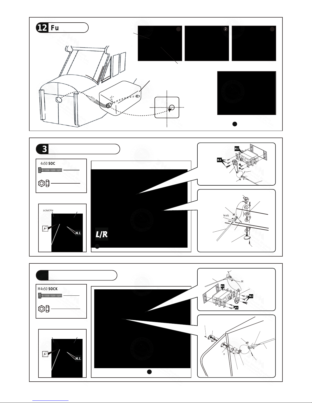
Fuel Tank 800cc
Double-sided Tape 40x160mm
M4 NYLON INSERT LOCK NUT
2
Bottom View
Completed
UP
Fuel Tank
12
Elevator Pushrod
13
Rudder
Pushrod
14
M2 x 10mm
PA1.7 x 8mm
Heavy Duty Clevis
Pushrod
Heavy Duty Horn Bracket
M4 x 50mm
M2 Nylon Insert
Lock Nut
M4 Nylon
Insert Lock
Nut
M2 x 10mm
Pushrod
Heavy Duty Servo Horn
M2 Nylon Insert Lock Nut
Cable Tie
1.5x8x500mm
1 2 3
2
M4x50 SOCKET HEAD SCREW
M4 NYLON INSERT LOCK NUT
1
Bottom View
M2 x 10mm
PA1.7 x 8mm
PA1.7 x 8mm
Heavy Duty Clevis
Pushrod
Heavy Duty Horn Bracket
M4 x 50mm
M2 Nylon Insert
Lock Nut
M4 Nylon
Insert Lock
Nut
1
M4x50 SOCKET HEAD SCREW
M2x8mm
Socket Head Screw
M2 Nut
PL4120300
M2x8mm
Socket Head Screw
M2 Nut
PL4120300
M2 x 10mm
Pushrod
Heavy Duty Servo Horn
M2 Nylon Insert Lock Nut
A037PO31141601

P.9
Flying Wire
15
Windows
16
Servo Set
17
PM2x16mm Screw
M2 Nut
6
6
PM2x8mm Screw
6
d2xD5mm Washer
12
Copper Tube
Wire
Press down the
center 1/3 portion
M2
PM2x16mm
PM2x16mm
d2.5xD3.2x8mm
2mm
2mm
d2xD5mm
Washer
M2 NUT
Throttle Pushrod
3x3mm
Washer
2mm
Washer
2mm
M2 Nut
Throttle Servo.
1.5mm
3x3mm Set Screw
M2 Nut
Linkage Connector
1
1
1
2
2mm Washer
Please refer to the attached sheet for linkage connector installation.
PM2x8mm
Balsa Rod
d6x190mm
Securely glue the windows to the fuselage.
A037PO31141601

P.10
Radio Equipment
18
Pilot
19
Wind Shield
20
lnstall and arrange the servo as shown in the diagram.
Bottom View
Balsa 10x10x240mm
Plywood 3x161.5x252mm
Battery
Battery
Sponge
Receiver
Throttle Servo
Throttle Pushrod
D1.8x430mm
Plastic tube
d2.5xD4x300mm
d2 x D5mm Washer
PWA 2x12mm Screw
4
PM2x14mm Screw
2
M2
2
4
Nylon Insert Lock Nut
PC001102A
PWA2x12mm Screw
PM2x14mm
Mounting Plate
Washer
d2xD5mm
Washer
d2xD5mm
M2 Nylon
Insert Lock
Nut
Instrument Panel
Charge Receptacles
A037PO31141601

P.11
Main Wing
21
Wing Struts
22
Wing Tube
Ø22x825mm
Lead to Aileron Servo
4
Set Screw
M3 x 8mm
Wing Tube PWA2x8mm
Self Tightening
Wing Latch
Set Screw
M3X8mm
M3x8mm
Set Screw
Wire Ø0.8mm
Completed
PM4x12mm Screw
d4x D12mm Washer
2
2
M4 NYLON INSERT LOCK NUT
2
HM4x12mm
M4 NYLON INSERT LOCK NUT
Washer
d4xD12mm
A037PO31141601

P.12
Wing Setting
23
Adjust the wing and fuselage configuration as shown in the diagrams.
A = A
'
A A
'
B = B
'
B B
'
C = C
'
C C
'
A037PO31141601

P.13
24
Control Throws
25
C.G
.
The ideal C.G. position is 124mm (4.9in.) behind the leading edge measured at where the wing meets the
fuselage. In order to obtain the C.G. specified, add weight to the fuselage or move the battery position.
Check the C.G. before flying.
If you are converting this model to electric, please move the C.G. forward 10% of current C.G. distance from
leading edge to compensate for weight of fuel.
124 mm
http://www.theworldmodels.com/para/instruction/instructionManuals.php
4.9 in.
C.G.
Important Safety Precautions
Warning!
#
First time flyer should never fly by himself / herself. Assistance from experienced flyer is absolutely
necessary.
#
Pre-flight adjustment must be done before flying, it is very dangerous to fly a badly pre-adjusted
aircraft.
#
is specially designed to be powered by 50c.c. gasoline engine, using a more
powerful engine does not mean better performance. In fact, over powered engine may cause
structural damage and injuries.
#
Make sure the air field is spacious, never fly the plane too close to people and never get too close
to a running propeller.
# If you find wrinkles on the covering as a result of weather changes, you can use hot iron to remove
the wrinkles. Please begin with lower temperature setting and gradually raise the temperature until
the wrinkles are gone. Too hot an iron may damage the covering.
Don't use hot iron near the seams
or edges, hot iron will melt the glue and shrink the covering at the same time, causing the seams to pull
away.
# Check and re-tighten up all factory assembled screws, use thread locker if necessary.
Adjust the control throws as shown in the diagram.
These throws are good for general flying. You can
adjust according to your personal preference.
Aileron
35mm
Elevator
45mm
Rudder
60mm
60mm
45mm
35mm
A037PO31141601

This transparent 3D template
is used for position guidance
of the actual cutting of the
pre-painted cowling.
Usage of the transparent 3D template
Simply cut the transparent 3D template to fit your engine and
exhaust pipe, then slide onto the actual cowling and use as
template to mark the openings required for final cutting.
1 2
3 4
A037PO31141601

A037PO31141601
 Loading...