


1/4 Clipped Wing Cub
0.91 cu. in. displacement 2-stroke
1.20-1.60 cu. in. displacement 4-stroke
Requires : 4 - channel radio w/ 4 high torque servos and
1 standard servo ( throttle)
Wing Span
Wing Area
Flying Weight
Fuselage Length
88.0 in / 2240 mm
1330 sq in / 85.8 sq dm
14.0-16.0 lbs / 6400-7300 g
65.0 in / 1650 mm
FACTORY PRE-FABRICATED
ALMOST-READY-TO-FLY(ARF)SERIES
MADE IN CHINA
* Specifications are subject to change without notice.*
Warning ! This model is not a toy.
It is designed for maximum performance. Please seek advice if one is not familiar with this kind
of electric powered precision model. Operating this model without prior preparation may cause
injuries. Remember, safety is the most important thing. Always keep this instructio n ma n ua l at
hand for quick reference.
INSTRUCTION MANUAL
Specifications
The World Models
Manufacturing Co., LTD.
www.theworldmodels.com
A057PO29971404
INDEX
BEFORE YOU BEGIN
BEFORE YOU BEGIN
PARTS LIST
ASSEMBLY
SAFETY PRECAUTIONS
P.1
P.2
P.3-P.13
P.13
Check all parts. If you find any defective or missing parts contact your local dealer. Please
DRY FIT and check for defects for all parts that will require CA or Epoxy for final assembly.
Any parts you find to be defective after the gluing process may be difficult to remove for
warranty replacement. The manufacturer will replace any defective parts, but will not extend
to the parts that are good before gluing to defective parts during assembly. Warranty will
not cover any parts modified by customer.
Symbols used throughout this instruction manual comprise of the following :-
Read through the manual before you begin, so you will have an overall idea of what to do.
1
2
3
Cut off shaded portion.
Ensure smooth non-binding
movement while assembling.
Apply instant glue
(C.A.glue, super glue.)
Assemble left and right
sides the same way.
Peel off shaded portion
covering film.
Pay close attention here!
Apply epoxy glue.
Must be purchased separately !
Drill holes with the specified
diameter (here: 3mm).
Pierce the shaded portion
covering film.
3mm
Do not overlook this symbol !
Warning!
Apply thread locker
1/4 Clipped Wing Cub
P.1
A057PO29971404
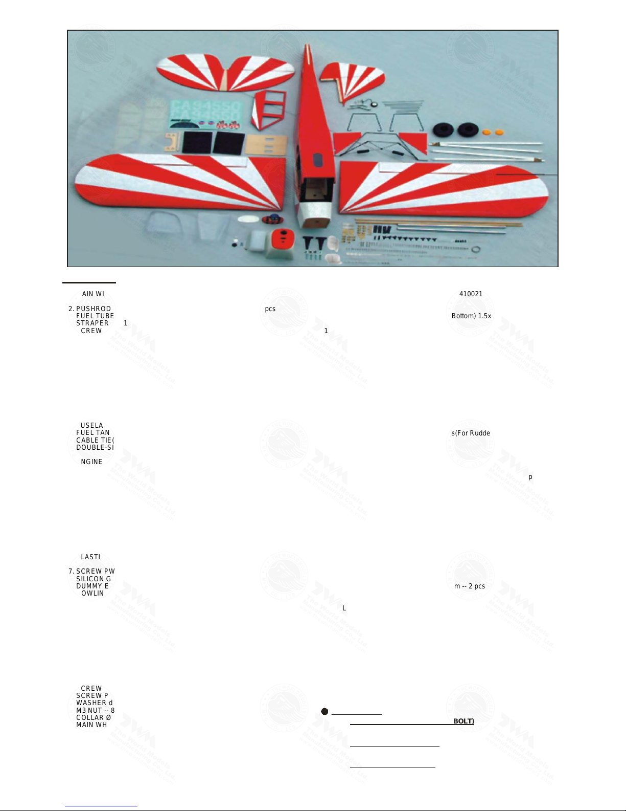
Parts List
COVERING:--
(CUB YELLOW WITH THUNDER BOLT)
TOUGHLON STL 201 BLACK
TOUGHLON STL 331 CUB YELLOW
(BLUE / WHITE SUNBURST)
TOUGHLON STL 100 WHITE
TOUGHLON STL 251 SKY BLUE
(RED / WHITE SUNBURST)
TOUGHLON STL 100 WHITE
TOUGHLON STL 312 BRIGHT RED
P.2
1. MAIN WING -- 1 pair
2. PUSHROD Ø1.8x120mm w/ Threads(For Aileron Servo) -- 2 pcs
FUEL TUBE Ø6x5mm -- 4 pcs
STRAPER PL4112102 -- 2 pcs
SCREW PB2x30mm -- 6 pcs
SCREW PWA2x8mm -- 8 pcs
SERVO MOUNTING PANEL PL5310000 -- 1 pair
CLEVIS PL4112103 -- 2 pcs
TRI-HORN M3x22mm(L) -- 2 sets
3. SOCKET HEAD SCREW M3x15mm -- 12 pcs
WASHER d3xD7mm -- 8 pcs
M3 NUT -- 4 pcs
MAIN WING STRUTS -- 1 set
WING STRUT WIRE Ø3x142x183mm -- 2 pcs
WIRE BRACKET PL5330030Y -- 8 pcs
4. FUSELAGE -- 1 pc.
FUEL TANK 500cc -- 1 set
CABLE TIE(For Fuel Tank) 1.5x5x400mm -- 1 pc.
DOUBLE-SIDED TAPE 40x100mm -- 1pc.
5. ENGINE MOUNT PL5111080 -- 1 set
SOCKET HEAD SCREW M4x30mm -- 4 pcs
WASHER d4.2xD14.5mm -- 4 pcs
M4 BLIND NUT -- 4 pcs
6. ALUMINUM PLATE(For Engine Mount) -- 1 pc.
ANTI-VIBRATION MOUNT PL5214094 -- 1 set
INCLUDE: SOCKET HEAD SCREW M4x35mm -- 4 pcs
SCERW KM3x20mm -- 8 pcs
WASHER d4xD12mm -- 8 pcs
NYLON INSERT LOCK NUT M3 -- 8 pcs
NYLON INSERT LOCK NUT M4 – 4 pcs
THROTTLE PUSHWIRE Ø1.2x480mm -- 1 pc.
PLASTIC TUBE d2xD3x300mm -- 1 pc.
7. SCREW PWA2.6x12mm -- 4 pcs
SILICON GROMMET d1.5xD6.5mm(For Cowling) -- 4 pcs
DUMMY ENGINE COVER -- 1 pair
COWLING -- 1 pc.
TRANSPARENT 3D TEMPLATE -- 1 pc.
8. SCREW PA3x12mm -- 2 pcs
SOCKET HEAD SCREW M3x14mm -- 2 pcs
WASHER d3xD7mm -- 2 pcs
ALUMINUM PLATE 2mm -- 2 pcs
9. MAIN LANDING GEAR -- 1 set
SCREW PA3x12mm -- 12 pcs
WASHER d3xD7mm -- 12 pcs
MOUNTING PLATE 12x20mm -- 6 pcs
10. SCREW PA1.7x8mm -- 6 pcs
SCREW PM3x13mm -- 8 pcs
WASHER d3xD7mm -- 16 pcs
M3 NUT -- 8 pcs
COLLAR Ø4.6mm w/ set screw -- 4 sets
MAIN WHEEL(CUB) Ø107mm -- 2 sets
PLYWOOD 3x145x171mm(Main Landing Gear Cover) -- 1 pair
WIRE BRACKET PL5330050Y -- 8 pcs
11. STABILZER & ELEVATOR -- 1 set
12. VERTICAL FIN & RUDDER -- 1 set
13. TAIL GEAR ASSEMBLY 11-22LBS PL3410021 -- 1 set
SCREW PA3x14mm -- 3 pcs
SCREW PWA2x12mm -- 3 pcs
PLATE(For Staying on Tail Fuselage Bottom) 1.5x10x34mm -- 1 pc.
14. FLYING WIRE Ø1x1300mm -- 1 pc.
FLYING WIRE BRACKET -- 6 pcs
FLYING WIRE BRACKET CLEVIS -- 4 pcs
EYE SCREW M1.8x6x12mm -- 4 pcs
SCREW PM2x16mm -- 6 pcs
SCREW PM2x8mm -- 4 pcs
M2 NUT -- 6 pcs
WASHER d2xD5mm -- 6 pcs
COPPER TUBE d2.5xD3.2x8mm (For Rudder) -- 8 pcs
15. SCREW PB2x16mm -- 3 pcs
FUEL TUBE Ø6x5mm -- 1 pc.
CLEVIS PL4112103 -- 1 pc.
TRI-HORN M3x22mm(L) -- 1 set
PUSHROD Ø1.8x1065mm w/ Threads(For Rudder Servo) -- 1 pc.
16. SCREW PB2x16mm -- 6 pcs
FUEL TUBE Ø6x5mm -- 2 pcs
CLEVIS PL4112103 -- 2 pcs
TRI-HORN M3x22mm(L) -- 2 sets
PUSHROD Ø1.8x995mm w/ Threads(For Elevator Servo) -- 2 pcs
17. LINKAGE CONNECTOR Ø2.1mm -- 1 set
18. PLYWOOD 3x152x218mm(For Fuselage Servo) -- 1 pc
19. FUEL TUBE Ø6x5mm -- 2 pcs
STRAPER PL4112102 -- 2 pcs
PUSHROD Ø1.8x85mm(For Elevator) -- 1 pc.
PUSHROD CONNECTOR 4x9x20mm -- 1 set
SPONGE 10x80x200mm -- 2 pcs
20. SCREW PWA2x12mm -- 4 pcs
PILOT PC001102A/B -- 1 set
SIDE WINDOWS -- 1 pair
COCKPIT BASE PANEL 3x145x165mm -- 2 pcs
21. SCREW PWA2.3x12mm -- 10 pcs
SILICON GROMMET d1.5xD6.5mm(For Wind Shield) -- 4 pcs
WIND SHIELD -- 1 pc.
22. WING TUBE Ø16x545mm -- 2 pcs
SCREW PA3x30mm -- 2 pcs
SOCKET HEAD SCREW M3x30mm -- 2 pcs
WASHER d3xD7mm -- 4 pcs
23. SOCKET HEAD SCREW M3x8mm -- 2 pcs
WASHER d3xD7mm -- 4 pcs
M3 NYLON INSERT LOCK NUT -- 2 pcs
24. DECALS: A057DEC -- 1 set
A057PO29971404
P.3
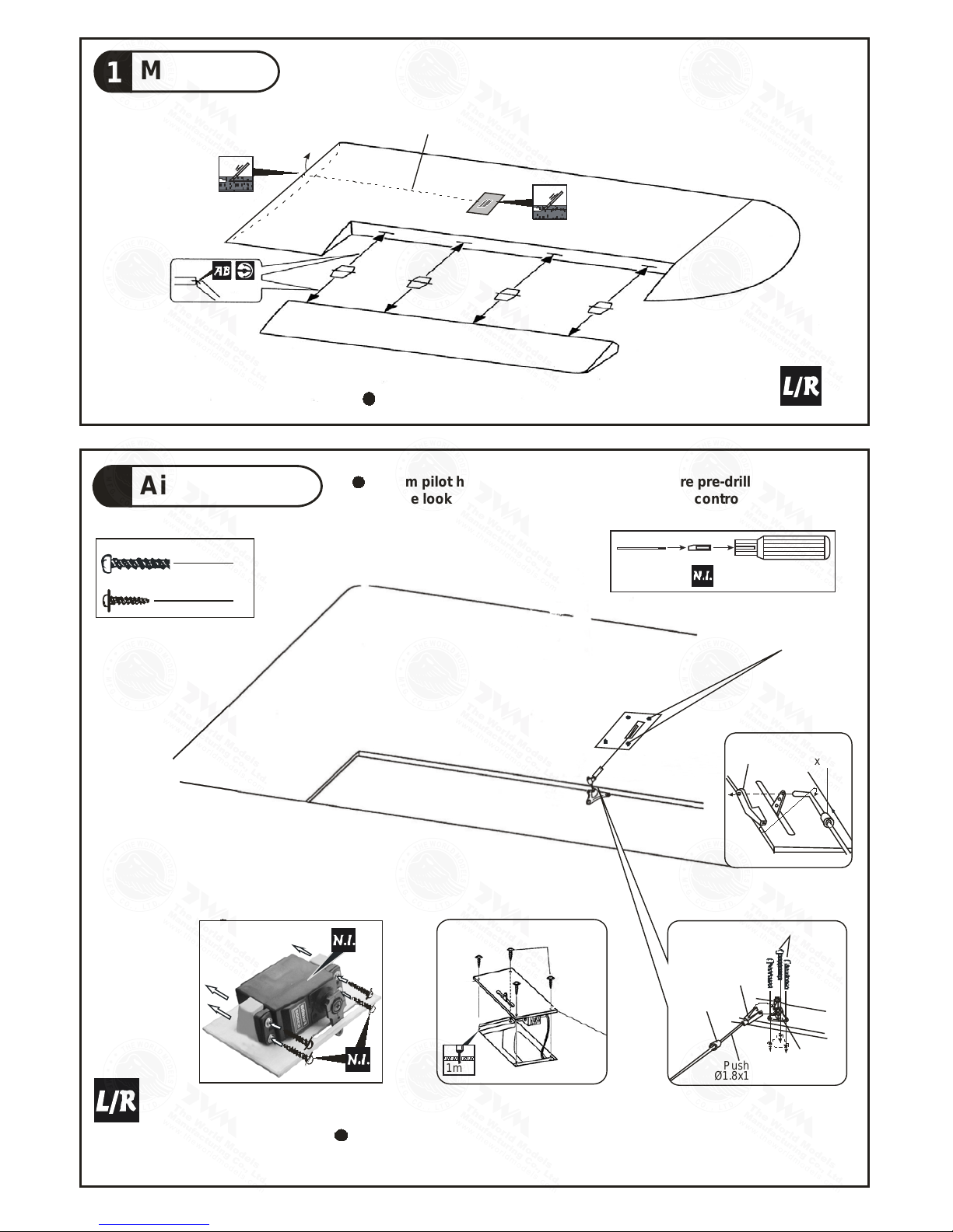
Main Wing
1
Pre-glued
Aileron Servo
2
Ø1mm pilot holes for World Models tri-horn are pre-drilled.
Please look for pin-hole marks at under side of control surfaces.
Bottom View
Fuel Tube
6x5mmØ
Straper
FuelTube
6x5mm
Ø
PB2x30mm
-Tri horn
M3x22mm
Clevis
Pushrod
1.8x120mmØ
6
PB2x30mm
Screw
8
PWA2x8mm Screw
Bottom View
PWA2x8mm
Aileron Servo Lead
PWA 2 x 8mm
1mm
1mm
TWM PL8210010
CLEVIS WRENCH
A057PO29971404
1
P.4
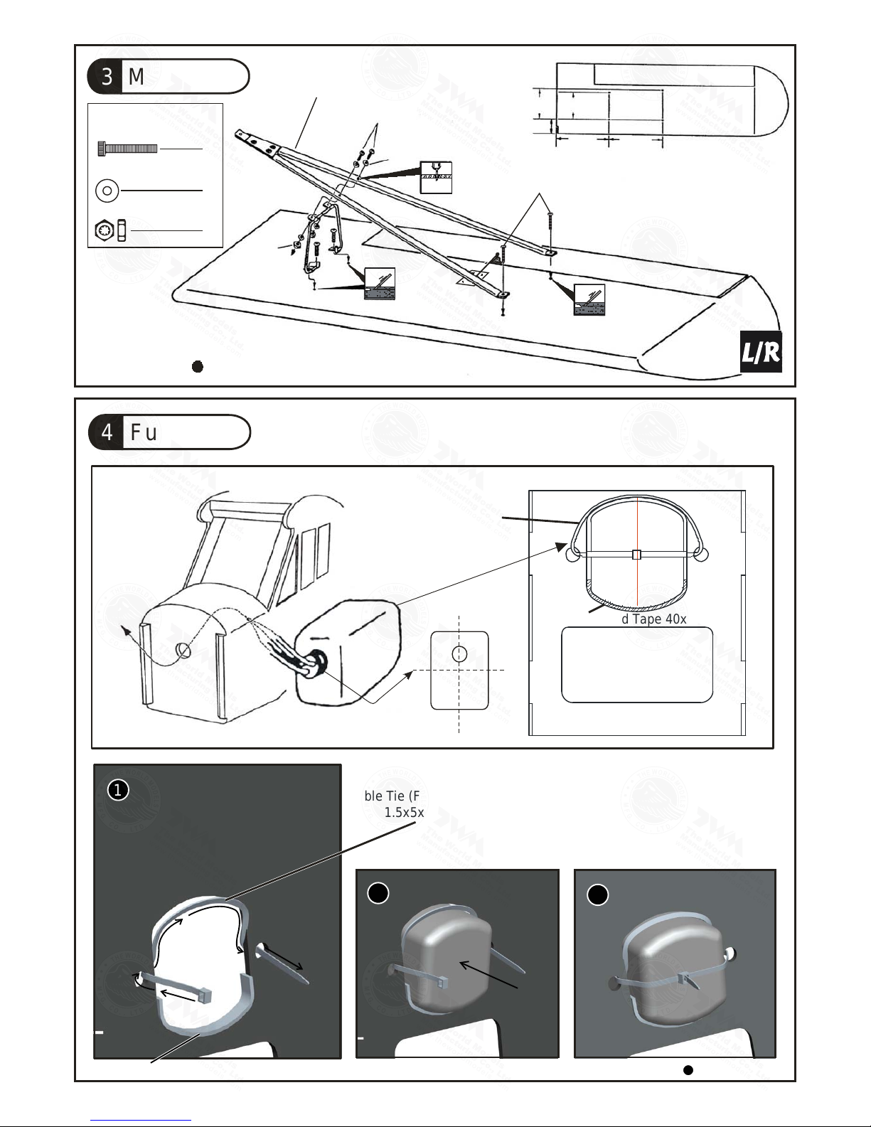
Fuel Tank4
Main Wing3
d3xD7mm Washer
M3 Nut
M3 Nut
M3x15mm
M3x15mm
Main Wing Strut
Washer
d3xD7mm
3.5mm
202mm
(7.95in.)
169mm
(6.56in.)
69mm
(2.72in.)
241mm
(9.48in.)
258mm
(10.15in.)
12
8
4
Bottom View
3mm
3
Cable Tie (For Fuel Tank)
1.5x5x400mm
Completed
F
u
e
l
T
a
n
k
500
c
c
UP
Double-sided Tape 40x100mm
Double-sided Tape 40x100mm
Cable Tie
(For Fuel Tank)
1.5x5x400mm
2
M3x15mm
Socket Head Screw
A057PO29971404
P.5
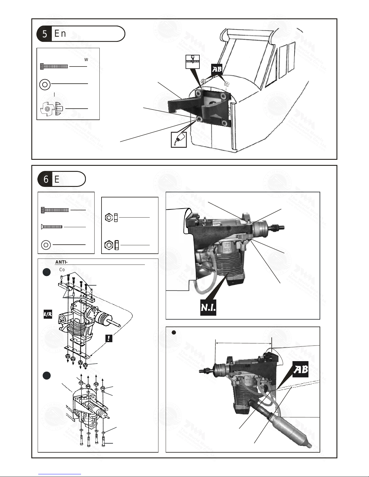
6 Engine
Throttle Pushwire
Ø1.2x480mm
Plastic Tube d2xD3x300mm
147mm
5.79 in.
Installed Engine Position
d4xD12mm Washer
M4 NYLON INSERT LOCK NUT
KM3x20mm Screw
8
4
M4x35mm
Socket Head Screw
M4x35mm
Socket Head Screw
d4xD12mm Washer
d4xD12mm
Washer
8
4
8
M3 NYLON
INSERT LOCK Nut
M4 NYLON
INSERT LOCK Nut
Copper Tube d4.1xD5x67.2mm
1
2
Make sure the rounded
edges are facing the
shock absorbing
SILICON PAD.
KM3x20mm
Copper Tube
d3.1xD4x7.2mm
M3 Nylon Insert
Lock Nut
ANTI-VIBRATION MOUNT INSTALLATION
M4 Nylon Insert
Lock Nut
d4xD12mm
Washer
d4xD12mm
Washer
M4x35mm
Socket Head
Screw
Engine Mount
5
Engine Mount
PL5111080
Washer
d4.2xD14.5mm
d4.2xD14.5mm Washer
M4 Blind Nut
4
4
7.5mm
Determine the angle of
installation of the engine
mount so the muffler
will not contact the
fuselage.
4
M4x30mm
Socket Head Screw
Socket Head Screw
M4x30mm
5.5mm
A057PO29971404
P.6
Main Landing Gear
Wing Struts Mounting Bracket8
HM3x13mm Screw
d3xD7mm Washer
2
2
2
Washer
d3xD7mm
Aluminum Plate 2mm
PA3x12mm
Washer
d3xD7mm
M3x14mm
PA3x12mm Screw
d3xD7mm Washer
12
12
PA3x12mm
Washer
d3xD7mm
Bottom View
Bottom View
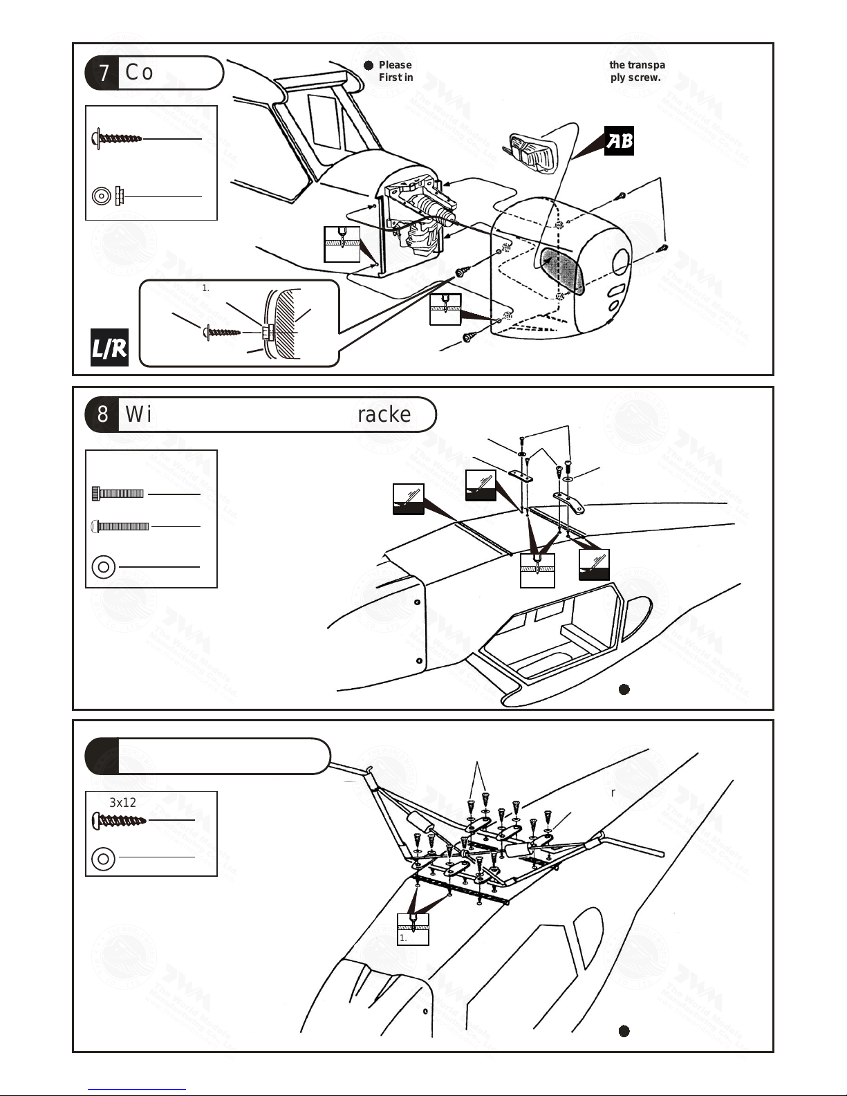
Cowling
7
PWA2.6x12mm Screw
d1.5xD6.5mm
Silicon Grommet
4
4
1mm
2.5mm
PWA2.6x12mm
PWA2.6x12mm
1mm
2.5mm
Please refer to the attached sheet for usage of the transparent 3D template.
First insert the grommet to the cowling then apply screw.
9
1mm
2.5mm
1mm
2.5mm
PWA2.6x12mm
d1.5xD6.5mm
Silicon Grommet
Cowling
1.5mm
1.5mm
1.5mm
1.5mm
M3x14mm
Socket Head Screw
A057PO29971404

P.7
C= C'
C
C'
Pre-glued
C=C
C
C
Pre-glued
Temporary install the main wing, adjust
leveling of the stabilizer to make it as
parallel to the main wing as possible.
PA1.7x8mm Screw
PA1.7x8mm
PM3x13mm Screw
PM3x13mm
d3xD7mm Washer
Washer
d3xD7mm
M3 Nut
M3 Nut
3mm Set Screw
4.6mm Wheel Collar
6
8
16
8
4
4
3.1mm
3.1mm
Bottom View
3.1mm
3.1mm
Vertical Fin / Rudder12
Stabilizer & Elevator11
Main Landing Gear10
(Stabilizer)
(Main Wing)
B B'
B=B'
A = A'
A A'
PM3x13mm
Washer
d3xD7mm
Wire Bracket
A057PO29971404

P.8
PB2x16mm Screw
Bottom View
3
Pushrod
Ø1. 8x1065
mm
Ø1mm pilot holes for The World Models tri-horn are pre-drilled.
Please look for pin-hole marks at under side of control surfaces.
Fuel Tube
Ø6x5mm
Clevis
Tri- horn
M3x22mm
PB2x16mm
M3 Nut
d3xD7mm Washer
PM3x18mm
d3xD7mm Wash
er
D2. 6mm
d2. 5xD3. 2x8mm
x3mm
Set
Scr
Copper Tube
Press down the center
1/3 portion
3mm
3mm
PM3x18mm Screw
d3xD7mm Washer
M3 N
t
3
6
3
3mm
3mm
TWM PL8210010
CLEVIS WRENCH
PM2x16mm Screw
6
4
PM2x8mm Screw
M2 Nut
M2 Nut
d2xD5mm Washer
Washer
d2xD5mm
Washer
d2xD5mm
6
6
M2 Nut
PM2x8mm
Clevis
d2.5xD3.2x8mm
d2.5xD3.2x8mm
PM2x16mm
PM2x8mm
2mm
2mm
Copper Plate
1x10x34mm
3.1mm Collar
1.5mm
1.5mm
Copper Plate
1.5x10x34mm
M3x3mm
Set Screw
PA3x14mm Screw
PA3x14mm
Bottom View
3
3
Set Screw
M3x3mm
PWA2x12mm Screw
15
Rudder Pushrod
14
Flying Wire
13 Tail Landing Gear
A057PO29971404

P.9
Clevis
Fuel Tube
Ø6x5mm
Tri-horn
M3x22mm
Pushrod
Ø1.8x995mm
16
Elevator Pushrod
TWM PL8210010
CLEVIS WRENCH
Ø1mm pilot holes for The World Models tri-horn are pre-drilled.
Please look for pin-hole marks at under side of control surfaces.
PB2x16mm Screw
PB2x16mm
6
3x3mm Set Screw
Linkage Connector
M2 Nut
M2 Nut
2mm Washer
2mm
Washer
2mm
Washer
Servo Tray
Servo Tray
18
Throttle Pushwire
Please refer to the attached sheet for linkage connector installation.
3mm
Throttle Servo
Servo Set
17
Plywood
3x152x218mm
2mm
2mm
1
1
1
2
A057PO29971404
P.10
4
Peel off shaded
Portion covering film
PWA2.3x12mm
Silicon Grommet
d1.5xD6.5mm
PWA2x12mm
1.5mm
Pilot
Cockpit Block
PWA2x12mm Screw
20
Windows
PWA2.3x12mm
10
4
PWA2.3x12mm Screw
d1.5xD6.5mm Silion Grommet
21
Wind Shield
1mm
2.5mm
Left Side
Right Side
KM2x8mm
M2 Nut
Elevator Pushrod
Ø1.8x85mm
Pushrod Connector
Elevator Servo
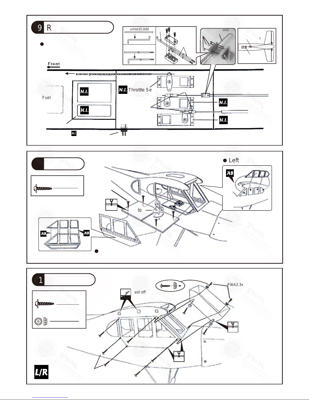
Install and arrange the servos
as shown in the diagram.
Receiver
Battery
Fuel Tank
450cc
Throttle Servo
Elevator Servo
Rudder Servo
Sponge 10x80x200mm
Fuel Tube
Ø6x5mm
Straper
To Throttle
J1(Pushrod Ø1.8x85mm)
J2(Pushrod Ø1.8x1000mm)
J1
J2
19 Radio Equipment
● Top View
Charge Receptacles
A057PO29971404

P.11
Main Wing
22
d3xD7mm Washer
2
4
PA3x30mm Screw
2
Top View
Left
Right
PA3x30mm
2.5mm
2.5mm
M3x30mm
Wing Tube
D16x545mm
180mm
180mm
60mm
135mm
2.5mm
2.5mm
Step 1. Insert the aluminum wing tube with the pre-drilled hole end into the right wing.
Align the lines marked at the wing root and wing tube and apply the HM3 x 30mm
machine screw through the pre-drilled hole on top of the wing. ( please confirm the
alignment of the hole by putting a 2.5mm diameter rod through the pre-drilled wing
hole before applying the screw ) The hole on the wing tube is pre-threaded, do not
over tighten the M3 x 30mm screw, the set up is for future removal of the wing.
Step 2. Install the right wing to the fuselage by inserting the wing tube (now attached to
the right wing) through the fuselage, then install the left wing.
Step 3. Make sure the wings are resting against the fuselage tightly. Locate the pre-drilled 2.5mm
hole at top of left wing, and drill along with 2.5mm drill bit until it passes through the wing tube.
Apply the PA3 x 30mm self-tapping screw.
Note : It is recommended that the wing tube stays with the left wing. Removal of the wings could
be acheived by removing the right wing machine screw, the right wing then the left wing with
wing tube. If removal of wing tube from left wing is also required, it is recommended that
instead of applying self-tapping screw in step 3, you pre-tap with M3 thread cutter and apply M3
machine screw.
d3xD7mm
Washer
d3xD7mm
Washer
M3x30mm
Socket Head Screw
A057PO29971404

P.12
Wing Setting
24
A=A’
B=B’
C=C’
D=D’
A
A'
B
B'
C
C'
D
D'
Control Throws
25
Aileron
20mm
20mm
Adjust the control throws as shown in
the diagram. These throws are good for
general flying. You can adjust according
to your personal preference.
Main Wing
23
M3x8mm
d3xD7mm Washer
Washer
d3xD7mm
M3 Nylon Inert Lock Nut
M3 Nylon Inert Lock Nut
2
4
2
55mm
55mm
Rudder
40mm
40mm
Elevator
M3x8mm
Socket Head Screw
A057PO29971404

P.13
Important Safety Precautions
# First time flyer should never fly by himself / herself. Assistance from experienced flyer is
absolutely necessary.
# Pre-flight adjustment must be done before flying, it is very dangerous to fly a badly
pre-adjusted aircraft.
# 1/4 Clipped Wing Cub is specially designed to be powered by 2C 0.91 or 4C 1.20 - 1.60
engine, using a morepowerful engine does not mean better performance. In fact, over
powered engine may cause severe damage and injuries.
# Make sure the air field is spacious, never fly the plane too close to people and never get
too close to a running propeller.
# If you find wrinkles on the covering as a result of weather changes, you can use hot iron
to remove the wrinkles. Please begin with lower temperature setting and gradually raise
the temperature until the wrinkles are gone. Too hot an iron may damage the covering.
Don,t use hot iron near the seams or edges,hot iron will melt the glue and shrink the
covering at the same time,causing the seams to pull away.
# Check and re-tighten up all factory assembled screws, use thread locker if necessary.
C.G.26
The ideal C.G. position is 112mm (4.41 in) behind
the leading edge measured at where the wing meets
the fuselage. In order to obtain the C.G. specified,
add weight to the fuselage or move the battery position.
Check the C.G. Before flying.
Warning!
A057PO29971404
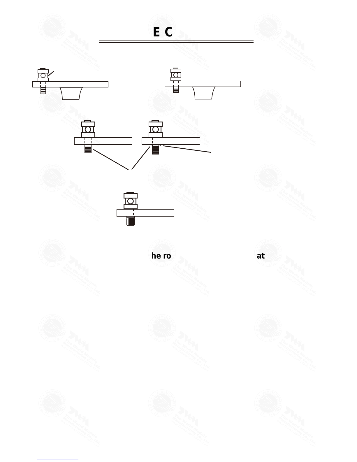
LINKAGE CONNECTOR
HW7111050 & HW7111060
After fastening the round nut, make sure that
the linkage connector can rotate freely.
Drill 2mm hole at servo horn.
Insert linkage connector
into servo horn.
Make sure shoulder of
screw is cleared from
servo horn.
Add washer to reduce
play if necessary.
Shoulder
Tighten up the round nut
against the shoulder. Apply
CA or permanent thread
locker.
A057PO29971404

Product Registration Form (US Customers)
We would like to share with you any relevant information regarding your model, including
product news and free upgrade parts when applicable. Please fill in the following and send to
AirBorne Models, 4749-K, Bennett Drive, Livermore, CA 94551 USA.
1. Name:______________________________________________
2. Address:____________________________________________
3. Phone #:____________________ E-mail:__________________
4. Model:______________________________________________
Wing QC#__________ Fuselage QC# _______________________
(QC numbers are stamped on wing and fuselage)
5. Date of Purchase:_____________________________________
6. Store Name: _________________________________________
Please call AirBorne Models a t 925 371 0922 for any assistanc e in filling this form.
Thank y ou very much for pur chasing our pro duct.
A057PO29971404
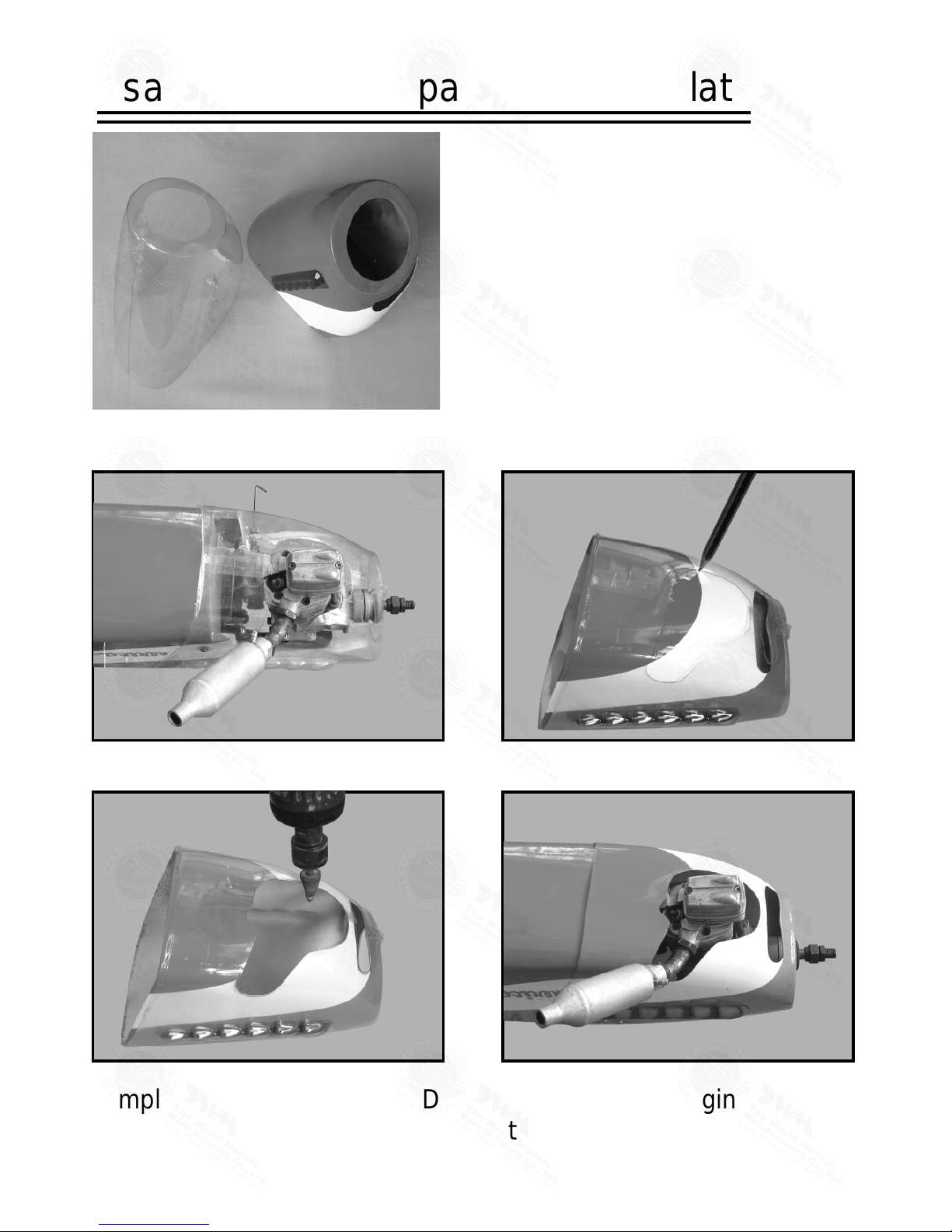
This transparent 3D template
is used for position guidance
of the actual cutting of the
pre-painted cowling.
Usage of the transparent 3D template
Simply cut the transparent 3D template to fit your engine and
exhaust pipe, then slide onto the actual cowling and use as
template to mark the openings required for final cutting.
1 2
3 4
A057PO29971404
Fuel Filter
Code No.
Size
Package
Code No.
Size
Package
Code No.
Size
Package
Code No.
Size
Package
Code No.
Size
Package
Code No.
Size
Package
Code No SV4031
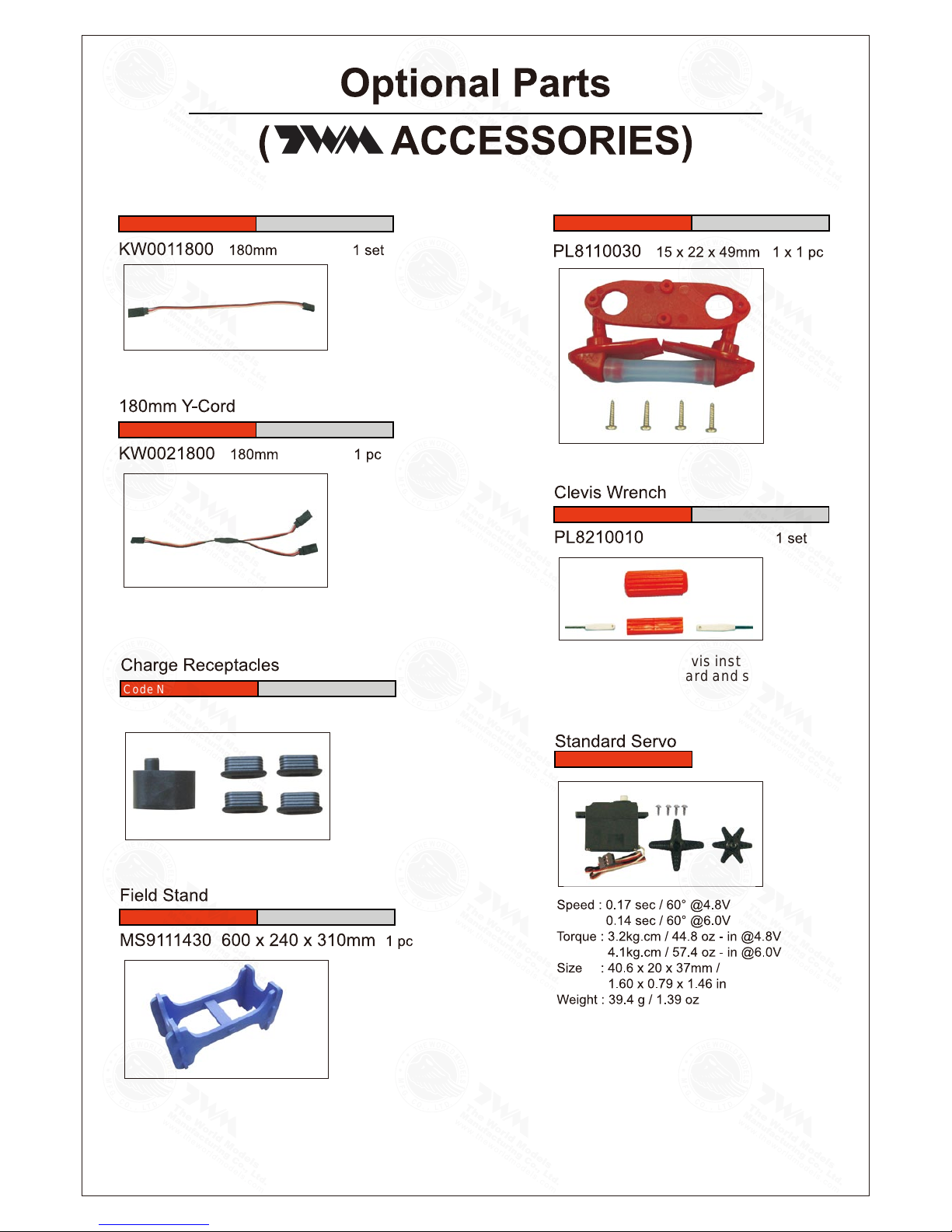
KP0041300
Special tool for clevis installation.
Suitable for standard and small
(EP)clevis.
Large Clevis
Small Clevis
180mm Extension
A057PO29971404

Code No.
Size
Package
PT1113040 D4xd2mm 1m(Transparent)
PT1113060 D6xd2.5mm 1m(Transparent blue)
PT1113082 D6xd3.2mm 1m(Red)
Silicon Tubes
Package
Code No.
Size
HW7120100 1 pc
Fuel Filter
Package
Code No.
Size
WF9112400 41-72x28x46.5cm 1 set
Wooden Field Stand (Painted)
Package
Code No.
Size
WCR572032 57-92x20x32mm
WCC572032 57-92x20x32mm
1 set
1 set
Wooden Field Box
1 pr
Package
Code No.
Size
MS6120040 D40-90mm (wheel)
Adjustable Wheel Chock
AT3001052 D260x900mm 1 pc
Code No. AT3001052
Size
Package
Wind sock
Package
1 set
Code No.
Size
MS9111500 200x115mm
Detachable Transmitter Stand
Package
Code No.
Size
PB2000618 210x115x35mm 1 set
Accessories Box with assorted
screws and hardwares
WCR572032
(Red)
WCC572032
(Cadmium Yellow)
(transparent blue) (red) (transparent)
A057PO29971404

A057PO29971404
 Loading...