


GA047SPO24121011
50CC
THE WINGS MAKER
FACTORY PRE-FABRICATED
ALMOST-READY-TO-FLY (ARF) SERIES
MADE IN CHINA
* Specifications are subject to change without notice.*
It is designed for maximum performance. Please seek advice if one is not familiar with this kind
of engine(electric) powered precision model. Operating this model without prior preparation may
cause injuries. Remember, safety is the most important thing. Always keep this instruction
manual at hand for quick reference.
Warning ! This model is not a toy.
Wing Span: 86 in / 2185 mm
Wing Area: 1408 sq in / 91 sq dm
Flying W eight: 18 lb / 8.2 kg
Fuselage Length: 82 in / 2085 mm
Requires: 50 c.c. gas engine ,4-channel
radio w/ 6-7 high torque servos
www.thewingsmaker.com
INSTRUCTION MANUAL
Before commencing assembly, please read these instructions thoroughly.
Specifications

GA047SPO24121011
INDEX
BEFORE YOU BEGIN
BEFORE YOU BEGIN
PARTS LIST
ASSEMBLY
SAFETY PRECAUTIONS
P.1
P.2
P.3-P.13
P.13
Check all parts. If you find any defective or missing parts contact your local dealer. Please
DRY FIT and check for defects for all parts that will require CA or Epoxy for final assembly.
Any parts you find to be defective after the gluing process may be difficult to remove for
warranty replacement. The manufacturer will replace any defective parts, but will not extend
to the parts that are good before gluing to defective parts during assembly. Warranty will
not cover any parts modified by customer.
Symbols used throughout this instruction manual comprise of the following :-
Read through the manual before you begin, so you will have an overall idea of what to do.
1
2
3
P.1
Cut off shaded portion.
Ensure smooth non-binding
movement while assembling.
Apply instant glue
(C.A.glue, super glue.)
Assemble left and right
sides the same way.
Peel off shaded portion
covering film.
Pay close attention here!
Apply epoxy glue.
Must be purchased separately !
Drill holes with the specified
diameter (here: 3mm).
Pierce the shaded portion
covering film.
3mm
Do not overlook this symbol !
Warning!
Apply thread locker
50CC

GA047SPO24121011
Parts List
P.2
COVERING:--
TOUGHLON STLGA047WIG
LIGHTEX SGX047GRN
LIGHTEX SGX047RED
1.MAIN WING -- 1 pair
2.SOCKET HEAD SCREW M4×65mm -- 2 pcs
M4 NYLON INSERT LOCK NUT -- 2 pcs
SWIVEL CLEVIS HORN FAIRING PL4610010 -- 2 sets
PUSHROD M3x78mm w/ Threads (For Aileron Servo) -- 2 pcs
HEAVY DUTY HORN BRACKET PL4112400 -- 2 pcs
HEAVY DUTY CLEVIS PL4112200 -- 4 sets
HEAVY DUTY HORN PL4120300 -- 2 sets
SERVO MOUNTING PANEL PL5310010(For Aileron) -- 1 pair
SCREW PWA2x8mm -- 8 pcs
3.STABILIZER & ELEVATOR -- 1 set
SOCKET HEAD SCREW M4×60mm -- 2 pcs
M4 NYLON INSERT LOCK NUT -- 2 pcs
SWIVEL CLEVIS HORN FAIRING PL4610010 -- 2 sets
PUSHROD M3x72mm w/ Threads (For Elevator Servo) -- 2 pcs
HEAVY DUTY CLEVIS PL4112200 -- 4 sets
HEAVY DUTY HORN PL4120300 -- 2 sets
HEAVY DUTY HORN BRACKET PL4112400 -- 2 pcs
4.FUSELAGE -- 1 pc.
STABILIZER TUBE Ø16X390mm -- 1 pc.
SCREW PA3x16mm -- 2 pcs
WASHER d3×D7mm -- 2 pcs
5.VERTICAL FIN & RUDDER -- 1 set
6.TAIL LANDING GEAR PL3410032 -- 1 set
SCREW PA3X18mm -- 3 pcs
SCREW PWA2.5X12mm -- 2 pcs
SPRING Ø5X40mm -- 2 pcs
7.THREADED ROD M4×100mm -- 1 pc.
M4 NYLON INSERT LOCK NUT -- 2 pcs
SWIVEL CLEVIS HORN FAIRING PL4610020 -- 1 set
EYE SCREW M2.5×8×25mm -- 4 pcs
WIRE Ø1×1050mm -- 2 pcs
COPPER TUBE d2.5×D3.2×8mm -- 4 pcs
HEAVY DUTY CLEVIS PL4112200 -- 4 sets
HEAVY DUTY HORN PL4120800 -- 1 set
HEAVY DUTY HORN BRACKET PL4112400 -- 2 pcs
8.MAIN LANDING GEAR -- 1 pc.
SCREW HM4×18mm -- 4 pcs
WASHER d4×D9mm -- 4 pcs
MAIN LANDING GEAR FARING -- 1 pair
SCREW HM3×16mm -- 4 pcs
M3 NUT -- 4 pcs
WASHER d3×D7mm -- 12 pcs
WHEEL PANTS -- 1 pair
SCREW HM3×10mm -- 4 pcs
WHEEL Ø90mm -- 2 pcs
WHEEL COLLAR Ø5.1mm w/ set screw -- 4 sets
AXLE SHAFT Ø5xM8x68mm -- 2 pcs
M8 NYLON INSERT LOCK NUT-- 2 pcs
WHEEL PANTS FARING -- 1 pair
ALUMINUM PLATE 1mm -- 2 pcs
9. ENGINE BOX 317x140x115mm -- 1 set
PLYWOOD(F54) 223x10x10mm -- 1 pc.
PLYWOOD(F54A) 230x10x10mm -- 1 pc.
PLYWOOD(F54B) 100x10x10mm -- 2 pcs
PLYWOOD(F54C) 140x10x10mm -- 2 pcs
PLYWOOD(F56) 95x10x10mm -- 6 pcs
10.FUEL TANK 800CC PL112800G -- 1 set
CABLE TIE (For Fuel Tank) 1.5×8×500mm -- 2 pcs
11.BLIND NUT M6 -- 4 pcs
SOCKET HEAD SCREW M6×50mm -- 4 pcs
WASHER d6×D15mm -- 4 pcs
FIREWALL DRILLING TEMPLATE 3×112×110mm -- 1 pc.
PUSHROD Ø1.8x470mm (For Throttle) -- 1 pc.
PLASTIC TUBE d2.5xD4x350mm (For Throttle) -- 1 pc.
PLYWOOD(F13) 142x142x3mm -- 1 pc.
12.LINKAGE CONNECTOR Ø2.1mm HW7111060 -- 1 set
13.SPONGE 10×80×200mm -- 2 pcs
14.TOP COWLING -- 1 pc.
UNDER COWLING -- 1 pc.
TRANSPARENT 3D TEMPLATE -- 1 pc.
SPINNER Ø102mm SP91102010 -- 1 set
SCREW HM3x20mm -- 4 pcs
WASHER d3xD7mm -- 4 pcs
QUICK RELEASE NYLON RIVET PL1208042 -- 12 pcs
SCREW KA2.3x8mm -- 12 pcs
15.WING TUBE Ø25×890mm -- 1 pc.
SELF TIGHTENING WING LATCH 6 mm w/ set screw -- 2 sets
WIRE Ø0.8mm -- 2 pcs
16.COCKPIT -- 1 set
CANOPY -- 1 pc.
SCREW HM3x20mm -- 2 pcs
WASHER d3×D7mm -- 2 pcs
PILOT PC101110F -- 1 set
17.PLYWOOD 110x100x3mm -- 1 pc.
SCREW PWA2.6x12mm -- 4 pcs
18.DECALS: GA047DEC -- 1 set
PROPELLER COVER AT3120020 -- 1 pair
*

GA047SPO24121011
P.3
Main Wing
1
Aileron Servos
2
Aileron Servo Lead
Pre-glued
Bottom View
Bottom View
Bottom View
M2x8mm
Socket Head Screw
M2 Nut
PL4120300
M2x10mm
Heavy Duty Clevis
Pushrod
M3x78mm
M3x78mm
Heavy Duty Horn Bracket
M4 x 65mm
M2 Nylon Insert
Lock Nut
M4 Nylon
Insert Lock
Nut
Completed
2
M4
2
Nylon Insert Lock Nut
M4x65mm
Socket Head Screw
PA1.7 x 8mm
PWA2x8mm Screw
8
M2 Nylon Insert
M2 x 10mm
Lock Nut
Pushrod
Heavy Duty
Clevis
1.5mm
PWA 2 x 8mm
1mm
GA047SPO24121011
P.4
Elevator Servos
3
Stabilizer & Elevator
4
Bottom View
Bottom View Bottom View
Completed
Completed
2
M4
2
Nylon Insert Lock Nut
M4x60mm
Socket Head Screw
PA3x16mm
2
Screw
d3xD7mm
Washer
2
M2x8mm
Socket Head Screw
M2 Nut
PL4120300
Pre-glued
Bottom view
Stabilizer Tube
Temporary install the main wing,adjust leveling of the stabilizer to
make it as parallel to the main wing as possible.
Ø16 x 390mm
M2x10mm
Heavy Duty Clevis
Pushrod
M3x72mm
Heavy Duty Horn Bracket
M4 x 72mm
M2 Nylon Insert
Lock Nut
M4 Nylon
Insert Lock
Nut
PA1.7 x 8mm
(Stabilizer)
(Main Wing)
B B'
B=B'
d3xD7mm
PA3x16mm
d3xD7mm
PA3x16mm
28mm
161mm
Pushrod
M3x72mm
M2 x 10mm
Heavy Duty Clevis
M2 Nylon Insert
Lock Nut
1.5mm

GA047SPO24121011
P.5
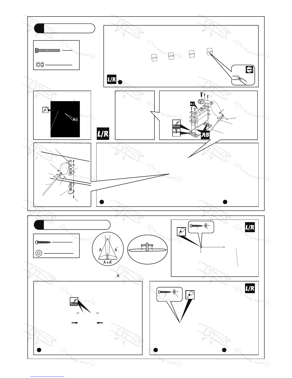
Vertical Fin & Rudder
5
Tail Landing Gear
6
Completed
Completed
Pre-glued
B B'
B=B'
Bottom View Bottom View
PWA2.5 x 12mm
PA3 x 18mm
Spring
Ø5x40mm
1.5mm 1 mm
3
Screw
PA3 x 18mm
2
Screw
PWA2.5 x 12mm

GA047SPO24121011
P.6
Rudder
7
Completed
Bottom View
Bottom View
1
2
M4x100mm Threaded Rod
M4 Nylon Insert Lock Nut
Ø
1x1050mm
wire
Eye Screw
M2.5x8x25mm
Front
Copper Tube
M2x10mm
Heavy Duty
Clevis
M2x8mm
PL4120800
M2 Nylon Insert
Lock Nut
M2 Nut
1
3
4
2
Heavy Duty Horn
Bracket
M4
Nylon Insert Lock Nut
M4x100mm
Threaded Rod
PA1.7 x 8mm
PA1.7 x 8mm
Wire
Ø 1x1050mm
Eye Screw
M2.5x8x25mm
Copper Tube
d2.5x3.2x8mm
Heavy Duty Clevis
M2x10mm
M2
Nylon Insert Lock Nut
Completed
Bottom View
4
M3 Nut
2
M8 Nut
4
d4xD9mm Washer
12
d3xD7mm Washer
4
2
HM4x18mm
4
HM3x16mm
HM3x10mm
4
Screw
Screw
Screw
Wheel Collar
5.1mm
4
Washer
d4xD9mm
HM4x18mm
Wheel Pants Faring(Right)
Wheel Pants
Faring(Left)
Wheel Pants
Faring(Left)
Landing Gear Faring(Left)
Landing Gear
Faring(Left)
Landing Gear
Faring(Right)
Main Landing Gear
8
Completed
Wheel
Pant
M3 Nut
d3xD7mm
Washer
d3xD7mm
Washer
HM3x16mm
Landing Gear Faring
/ Wheel Pants Faring
M3 Nut
d3xD7mm
Washer
d3xD7mm
Washer
HM3x16mm
Landing Gear Faring
/ Wheel Pants Faring
1
2
HM3x10mm
Washer
d3xD7mm
Wheel Ø90mm
Wheel Pants
Faring(Left)
Wheel Collar
5.1mm
Wheel Collar
5.1mm
Set Screw
3mm
5xM8x68mm
Ø
Axle Shaft
M8
Nylon Insert
Lock Nut
Aluminum Plate
Ø
5xM8x68mm
Axle Shaft
Press down the
center 1/3 portion
R
R L
L

GA047SPO24121011
Engine Box
9
P.7
Fuel Tank
800cc
Fuel Tank
800cc
CABLE TIE
(For Fuel Tank)
1.5x8x500mm
CABLE TIE
(For Fuel Tank)
1.5x8x500mm
Fuel Tank
10
Please note right & down thrust angle of firewall.
Use epoxy to glue all parts together.
Engine Box
F54C
F54A
0
°
3°
F54
F54A
F56 F56
F56
F56
F54B
F54B

GA047SPO24121011
P.8
4
d6xD15mm Washer
4
M6x50mm
Socket Head Screw
Engine thrust line
160mm
6.27 in.
Center line of firewall
Firewall Drilling Template
3x112x110mm(For DA 50 Engine)
Engine
11
Bottom View
Top View SideView
Front View
Install Engine position
Front View
4
M6 Blind Nut
Throttle Pushrod
Ø1.8x470mm
Plastic Tube
d2.5xD4x350mm
d6xD15mm Washer
M6x50mm
Socket Head Screw
M6 Blind Nut
8.4mm
≈65mm
For DA 50 Engine
Servo Set
12
Throttle Pushwire
3x3mm Set Screw
Washer
2mm
Washer
2mm
M2 Nut
Throttle Servo.
1.5mm
Please refer to the attached sheet for linkage connector installation.
3x3mm Set Screw
M2 Nut
Linkage Conne ctor
1
1
1
2
2mm Washer
5mm
3x142x142mm
F54C

GA047SPO24121011
P.9
Radio Equipment
13
Cowling & Spinner
14
Install and arrange the servo as shown in the diagram.
Temporarily mount cowl to fuselage using the HM3x20mm bolts with
d3xD7mm flat washers.Two of the bolts install from the rear of F-1 and
two of the bolts install from the front of the cowl at the bottom of F-1.
Receiver
Sponge
10x80x200mm
Throttle Servo
Rudder Servo
Plastic Tube
d2.5xD4x350mm
Throttle Pushrod
Ø1.8x470mm
Charge Receptacles
KP0041300
Battery
Bottom View
Under Cowling Top Cowling
Completed
HM3x20mm
d3xD7mm
Spinner
Ø 102 mm
4
Washer
4
KA2.3x8mm
12
Screw
Screw
Quick Release Nylon Rivet
d2xD8mm
12
KA2.3x8mm
d2xD8mm
Quick Release Nylon Rivet
d3xD7mm
HM3x20mm
d3xD7mm
HM3x20mm

GA047SPO24121011
P.10
Main Wing
15
Completed
4
Wing Tube
Ø25.4 x 890 mm
Lead to Aileron Servo
Screw
PWA2 x 12mm
PWA2x12mm
PWA2x12mm
Wing Tube
Wing Tube
Self Tightening
Wing Latch
Self Tightening
Wing Latch
Wire Ø0.8mm
Set Screw
M3X6mm
Self Tightening
Wing Latch
Wing Tube

GA047SPO24121011
P.11
Cockpit & Pilot
16
2
Socket Head Screw
Washer
2
Front
Front
Front
Completed
M3x20mm
Pilot PC101110F
Pilot PC101110F
Cockpit
Canopy
d3xD7 mm
Washer
M3x20 mm
d3xD7 mm
Apply thick CA or
Canopy glue.

GA047SPO24121011
P.12
Pipes Cover
17
Decals
18
4
Screw
PWA2.6x12 mm
PWA2.6x12 mm
PWA2.6x12 mm
Bottom View

GA047SPO24121011
P.13
Control Throws
19
C.G.
20
# First time flyer should never fly by himself / herself. Assistance from experienced flyer is absolutely necessary.
# Pre-flight adjustment must be done before flying, it is very dangerous to fly a badly pre-adjusted aircraft.
# is specially designed to be powered by 50 c.c. gasoline engine, using a more powerful
engine does not mean better performance. In fact, over powered engine may cause structural damage and injuries.
# Make sure the air field is spacious, never fly the plane too close to people and never get too close to a running
propeller.
# If you find wrinkles on the covering as a result of weather changes, you can use hot iron to remove the wrinkles.
Please begin with lower temperature setting and gradually raise the temperature until the wrinkles are gone. Too
hot an iron may damage the covering. Don't use hot iron near the seams or edges, hot iron will melt the glue and
shrink the covering at the same time, causing the seams to pull away .
# Check and re-tighten up all factory assembled screws, use thread locker if necessary.
The ideal C.G. position is 153mm ( 6 in. ) behind the leading edge measured at
where the wing meets the fuselage. In order to obtain the C.G. specified, add weight
to the fuselage or move the battery position. Check the C.G. before flying.
Adjust the control throws as shown in the
diagram. These throws are good for general
flying. You can adjust according to your
personal preference.
Elevator
Rudder
Aileron
Important Safety Precautions
Warning!
60 mm
60 mm
30 mm
30 mm
25 mm
25 mm
153mm
C.G.
6 in.
50CC

GA047SPO24121011
LINKAGE CONNECTOR
HW7111050 & HW7111060
After fastening the round nut, make sure that
the linkage connector can rotate freely.
Drill 2mm hole at servo horn.
Insert linkage connector
into servo horn.
Make sure shoulder of
screw is cleared from
servo horn.
Add washer to reduce
play if necessary.
Shoulder
Tighten up the round nut
against the shoulder. Apply
CA or permanent thread
locker.

GA047SPO24121011
Product Registration Form (US Customers)
We would like to share with you any relevant information regarding your model, including
product news and free upgrade parts when applicable. Please fill in the following and
send to AirBorne Models, 4749-K,Bennett Drive, Livermore, CA 94551 USA.
1. Name:______________________________________________
2. Address:____________________________________________
3. Phone #:____________________ E-mail:__________________
4. Model:______________________________________________
Wing QC#__________ Fuselage QC# _______________________
(QC numbers are stamped on wing and fuselage)
5. Date of Purchase:_____________________________________
6. Store Name: _________________________________________
Please call AirBorne Models at 925 371 0922 for any assistance in filling this
form.Thank you very much for purchasing our product.

GA047SPO24121011
This transparent 3D template
is used for position guidance
of the actual cutting of the
pre-painted cowling.
Usage of the transparent 3D template
Simply cut the transparent 3D template to fit your engine and
exhaust pipe, then slide onto the actual cowling and use as
template to mark the openings required for final cutting.
1 2
3 4

GA047SPO24121011
Optional Parts
Clevis Wrench
Code No. Size Package
PL8210010 1 set
Small Clevis
Large Clevis
Field Stand
Code No. Size Package
MS9111450 600 x 240 x 350mm 1 pc
( ACCESSORIES)
180mm Extension
Code No. Size Package
KW0011800 180mm 1 set
Charge Receptacles
Code No. Size Package
KP0041300
180mm Y-Cord
Code No. Size Package
KW0021800 180mm 1 pc
Special tool for clevis installation.
Suitable for standard and small
(EP) clevis.

GA047SPO24121011

GA047SPO24121011
THE WINGS MAKER
www. thewingsmaker.com
 Loading...