

Page 1
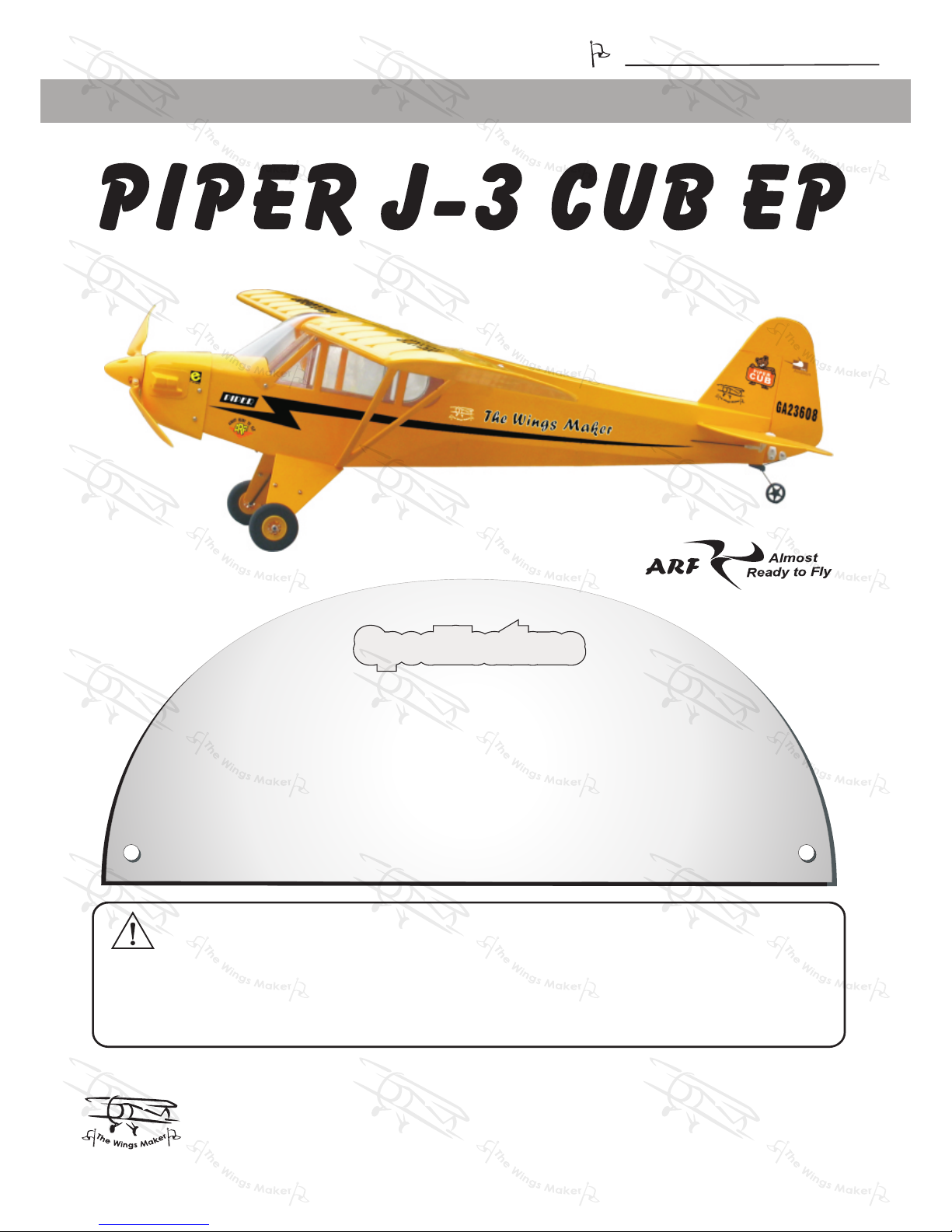
THE WINGS MAKER
FACTORY PRE-FABRICATED
ALMOST-READY-TO-FLY (ARF) SERIES
MADE IN CHINA
* Specifications are subject to change without notice.*
It is designed for maximum performance. Please seek advice if one is not familiar with this kind
of electric powered precision model. Operating this model without prior preparation may cause
injuries. Remember, safety is the most important thing. Always keep this instruction manual at
hand for quick reference.
Warning ! This model is not a toy.
Wing Span: 48.5 in / 1230 mm
Wing Area: 330 sq in / 21.3 sq dm
Flying Weight: 26 oz / 740 g
Fuselage Length: 30.5 in / 760 mm
Requires : Speed 400 motor, 4- channel radio
w/ 4 micro servos, 15A speed controller
and 7- 8 cells 1000 mAh battery
Specifications
Before commencing assembly, please read these instructions thoroughly.
Specifications
www. t hewings maker. co m
INSTRUCTION MANUAL
GE016
Page 2
P.1
INDE X
BEFORE YOU BEGIN
PARTS LIST
ASSEMBLY
SAFETY PRECAUTIONS
P. 1
P. 2
P.3-P.10
P. 10
BEFORE YOU BEGIN
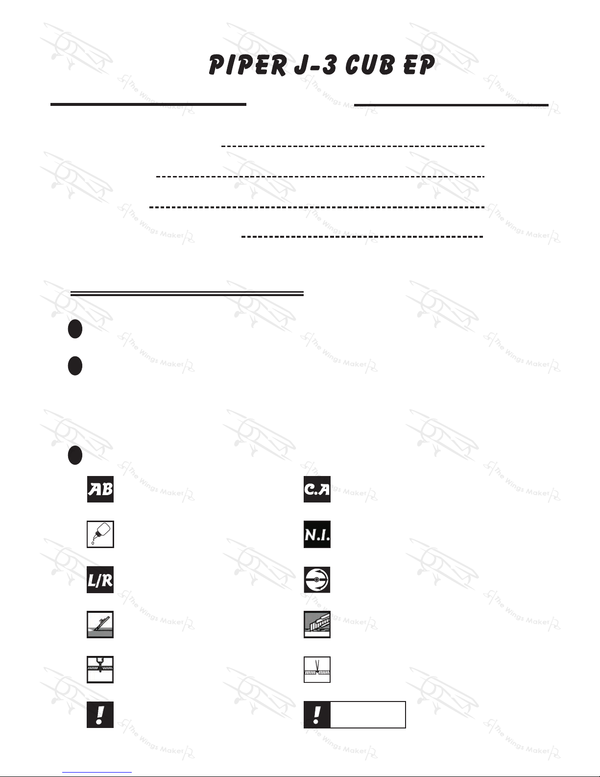
Do not overlook this symbol!
Cut off shaded portion.
Ensure smooth non-binding
movement while assembling.
Apply instant glue
(C.A.glue, super glue.)
Apply epoxy glue.
Pierce the shaded portion
covering film.
Must be purchased separately!
Peel off shaded portion
covering film.
Pay close attention here!
Drill holes with the specified
diameter (here: 3mm).
3mm
Warning!
Check all parts. If you find any defective or missing parts contact your local dealer Please DRY FIT
and check for defects for all parts that will require CA or Epoxy for final assembly. Any parts you
find to be defective after the gluing process may be difficult to remove for warranty replacement.
The manufacturer will replace any defective parts, but will not extend to the parts that are good
before gluing to defective parts during assembly. Warranty will not cover any parts modified
by customer.
.
Read through the manual before you begin, so you will have an overall idea of what to do.
1
2
3
Apply thread locker
Symbols used throughtout this instruction manual comprise of the following :-
Assemble left and right
sides the same way.
Page 3
P.2
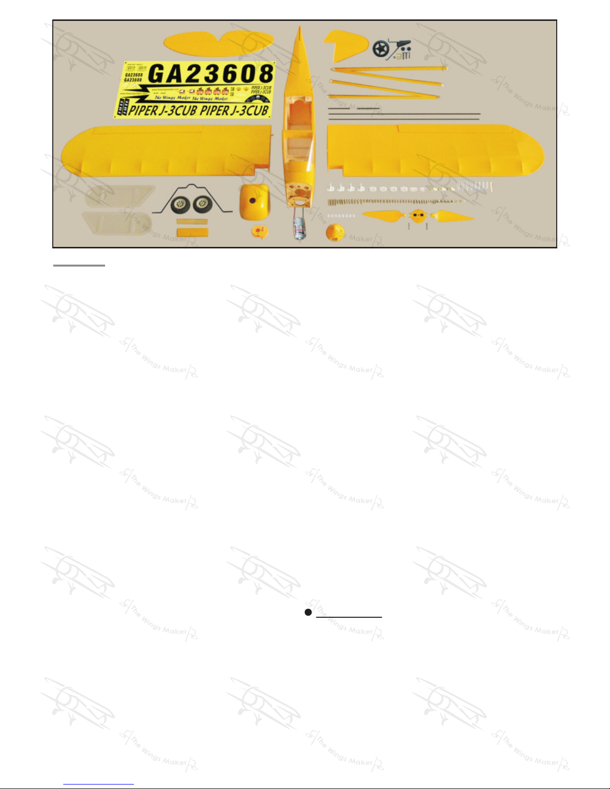
Parts List
COVERIN G:--
LIGHTEX S GX 331 CUB YELLOW
1. MAIN WING -- 1 pair
2. PUSHROD Ø1.4x70mm w/ Threads (For Aileron) -- 2 pcs
HORN -- 2 sets
CLEVIS -- 2 pcs
STRAPER -- 2 pcs
FUEL TUBE Ø4x4mm -- 4 pcs
SCREW PM2x18mm -- 4 pcs
3. PLYWOOD 5x13x82mm(Wing Joiner) -- 1 pc.
4. STABILIZER & ELEVATOR -- 1 set
FUSELAGE -- 1 pc.
ELEVATOR LINK PL4510010 -- 1 pc.
SCREW PM2x8mm -- 2 pcs
5. VERTICAL FIN & RUDDER -- 1 set
6. TAIL LANDING GEAR -- 1 set
SCREW PA2x8mm -- 2 pcs
BALSA 3x6x7mm -- 1 pc.
SCREW PM2x8mm -- 1 pc.
M2 NUT -- 1 pc.
AI REINFORCEMENT PLATE -- 1pc.
7. FUEL TUBE Ø4x4mm -- 1 pc.
CLEVIS -- 1 pc.
PUSHROD Ø1.4x415mm w/ Threads(For Elevator) -- 1 pc.
8. PUSHROD Ø1.4x420mm w/ Threads(For Rudder) -- 1 pc.
FUEL TUBE Ø4x4mm -- 1 pc.
CLEVIS -- 1 pc.
HORN -- 1 set
SCREW PM2x8mm -- 2 pcs
9. SPEED 400 MOTOR -- 1 set
GEAR BOX -- 1 set
PROPELLER -- 1 pair
SPINNER Ø36mm -- 1 set
COWLING -- 1 pc.
DUMMY ENGINE COVER -- 1 pair
MOUNT PLATE (PL4114015) -- 1 pc.
SCREW PWA2x8mm -- 4 pcs
WASHER d2xD5mm -- 1 pc.
M2 NYLON INSERT LOCK NUT -- 1 pc.
SCREW PM2x10mm -- 1 pc.
10. WIND SHIELD & SIDE WINDOWS -- 1 set
SCREW PWA2x8mm -- 4 pcs
11. SPONGE 10x50x150mm -- 1 pc.
DOUBLE-SIDED TAPE 30x35mm --1 pc.
FUEL TUBE Ø4x4mm -- 2 pcs
BATTERY TIE -- 1 pc.
STRAPER -- 2 pcs
12. MAIN LANDING GEAR --1 set
MAIN WHEEL Ø50mm-- 2 pcs
LANDING WIRE STRAPS (PL4114030) -- 3 pcs
PVC PLATE 0.5x6x32mm (For Main Landing Gear) -- 2 pcs
BALSA 22x73x80mm (Main Landing Gear Cover) -- 2 pcs
SCREW PA2.6x10mm -- 6 pcs
COLLAR Ø2.6mm w/ set screw -- 4 sets
SCREW PM2x6mm -- 4 pcs
WASHER d2xD5mm -- 4 pcs
M2 NUT -- 4 pcs
TRANSPARENT DECALS 20x70mm -- 4 pcs
13. SCREW PM2.5x25mm -- 2 pcs
WASHER d2.6xD7mm -- 2 pcs
BALSA 6x25x82mm (Wing Protection) -- 1 pc.
14. SCREW PA2.3x8mm -- 6 pcs
MAIN WING STRUTS -- 1 pair
15. DECALS -- 1 set
Page 4
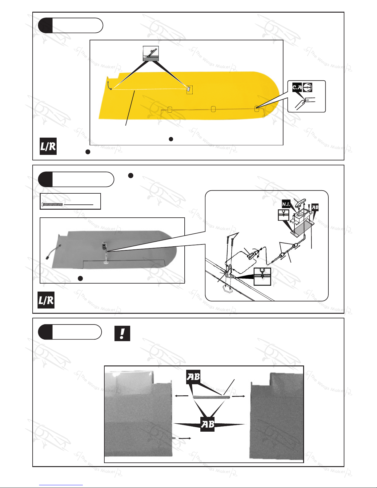
Main Wing
1
P.3
Bottom View
Apply i n s t a nt type C A g l u e to b o t h sides o f each h i n g e .
Main Wing
3
Wing J oiner
5x13 x82mm
Aileron Servo
2
4
PM2x18mm Screw
Ø1mm pilot holes for The Wings tri-horn are pre-drilled. Please
look for pin-hole marks at under side of control surfaces.
Maker
Bottom View
PM2x18mm
Pushrod
d2xD4x4mm
Clevis
2mm
Horn
Fuel Tube
Straper
1mm
Ø1.4x70mm
1mm
Plywood
3x6x12mm
Aileron Serv o lead
Plea se dry fit wi ng joiner i nto left an d right win g to make sur e they fit wi th
the pr oper dihe dral angl e, mark the w ing joine r if necess ary. App ly epo xy
glue to both s ides of a ll surfa ces in contact . Use a s tick to a pply the gl ue
to in ner si de of win g joiner sleev e, and ap ply th e glue to w ing join er befor e
putt ing them toget her. Wing j oiner no t glue d proper ly will l ead to wing fai lure
and pl ane cras h.
Page 5
P.4
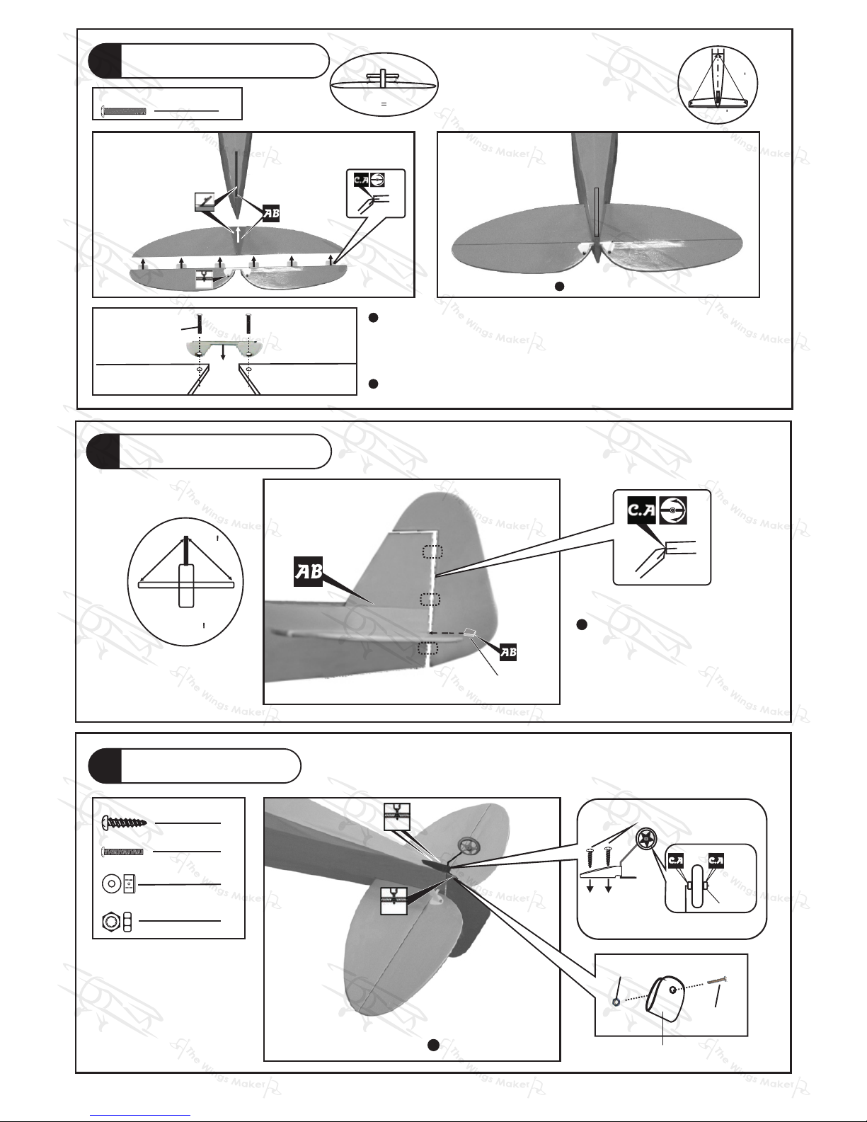
Stabilizer & Elevator
4
1mm
Tail Landing Gear
PA2 x 8mm Screw
2
1mm
Bottom View
Pla stic Co llar
PA2x8mm
PM2 x 8mm Screw
1
2
2.6mm Collar
M2 Nut
1
M2 Nut
PM2 x 8mm
Completed
Bals a
3x6x 7mm
App l y ins ta nt ty pe CA
glu e to bot h si d es of
eac h hi n ge.
C=
C
C
C
6
Rudder & Vertical Fin
5
2mm
2
PM2x8mm Screw
(St abili zer)
(Ma in Wing )
B
B'
*Als o refer to st ep 15 Wing Sett ing
Temporary insta ll the main wing, adjus t
lev eling of the stabi lizer to make it as
par allel to the main wing as possible.
Apply in stant type CA glue to b oth sides of each hinge .
PM2x8mm
Completed
A=A
A
A
Ø1mm pilot holes for Wings Maker tri-horn are pre-drilled.
Please loodforpin-holemarks at under sideof controlsurfaces.
Ai Reinforcement Plate
Page 6
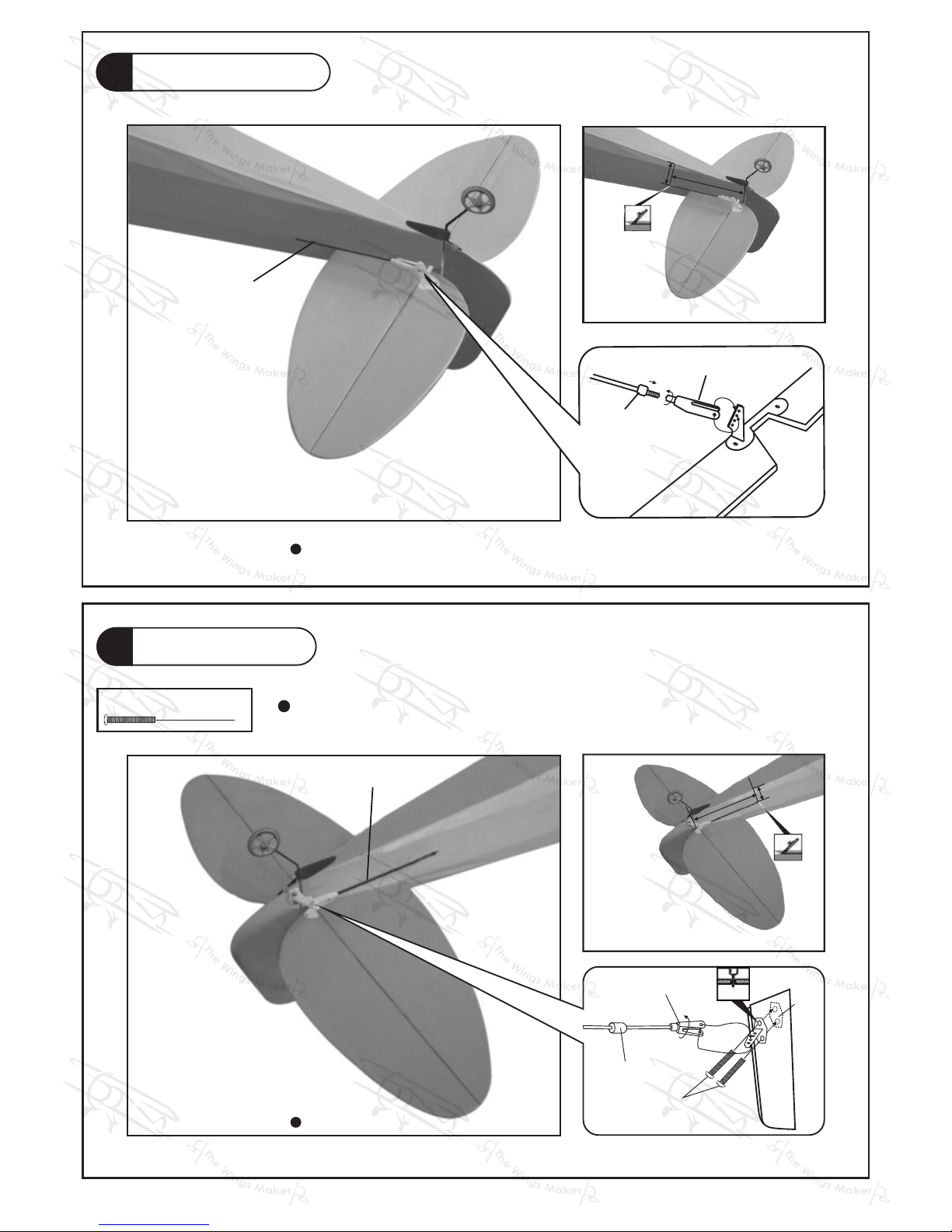
Elevator Pushrod
7
Rudder Pushrod
8
2
PM2 x 8mm Screw
Ø1mm pilot holes for tri-horn are pre-drilled. Please look
for pin-hole marks at side of control surfaces.
The Wings Maker
P.5
Ø1.4x41 5mm
Pushrod
Bottom View
≈70mm
≈23
mm
PM2 x 8mm
Clevis
Fuel Tube
d2xD4x4mm
Bottom View
Pushrod
Ø1.4x42 0mm
≈65mm
≈20mm
2mm
Horn
Cl
evis
Fue
l Tube
d2x
D4x4
mm
Page 7
P.6
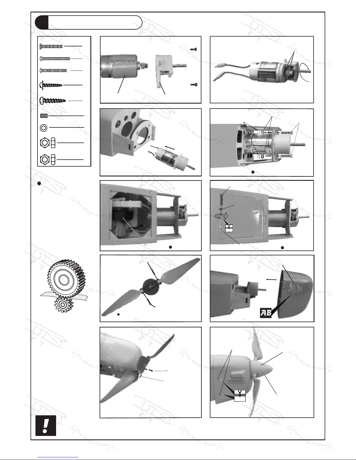
Don't over-tightenthe PM2 screws, let the
propellerblades align themselves when spinning.
PM2 x 12mm
Spinner
PA2.6 x 8mm
PWA2 x 8mm
10
1.5mm
8
7
PM2 x 12mm
3mm Set Screw
9
Ø1.2x35mm
Steel Wire
Motor / Cowling Setting
TO ALLOW FOR
BACKLASH OF
MATCHING GEAR,
PUT A PIECE OF
THIN PAPER
BETWEEN THE
GEARS AND
THEN TIGHTEN
THE M2.6X7mm
SCREWS. REMOVE
THE PAPER
BEFORE FLYING.
1
3
9
2
M2.6 x 7mm
PM2 X 10mm
2mm
Bottom View
6
M2 Nylon Insert Lock Nut
d2xD5mm
Was he r
4
PM2 x 12mm
Top Vi ew
Was he r d2 x D 5m m
M2 Nut
PWA2 x 8mm Screw
4
2
M2.6 x 7mm Socket Head Screw
1
3mm Set Screw
PM2 x 12mm Screw
4
2
PA2.6 x 8mm Screw
PM2 x 10mm Screw
1
M2 Nylon Insert Lock Nut
1
d2 x D5mm Washer
3
M2 NUT
2
Battery
Battery Tie
Bottom View
5
DUMMY ENGINE COVER
Speed 400 Motor Gear Box
Page 8
P.7
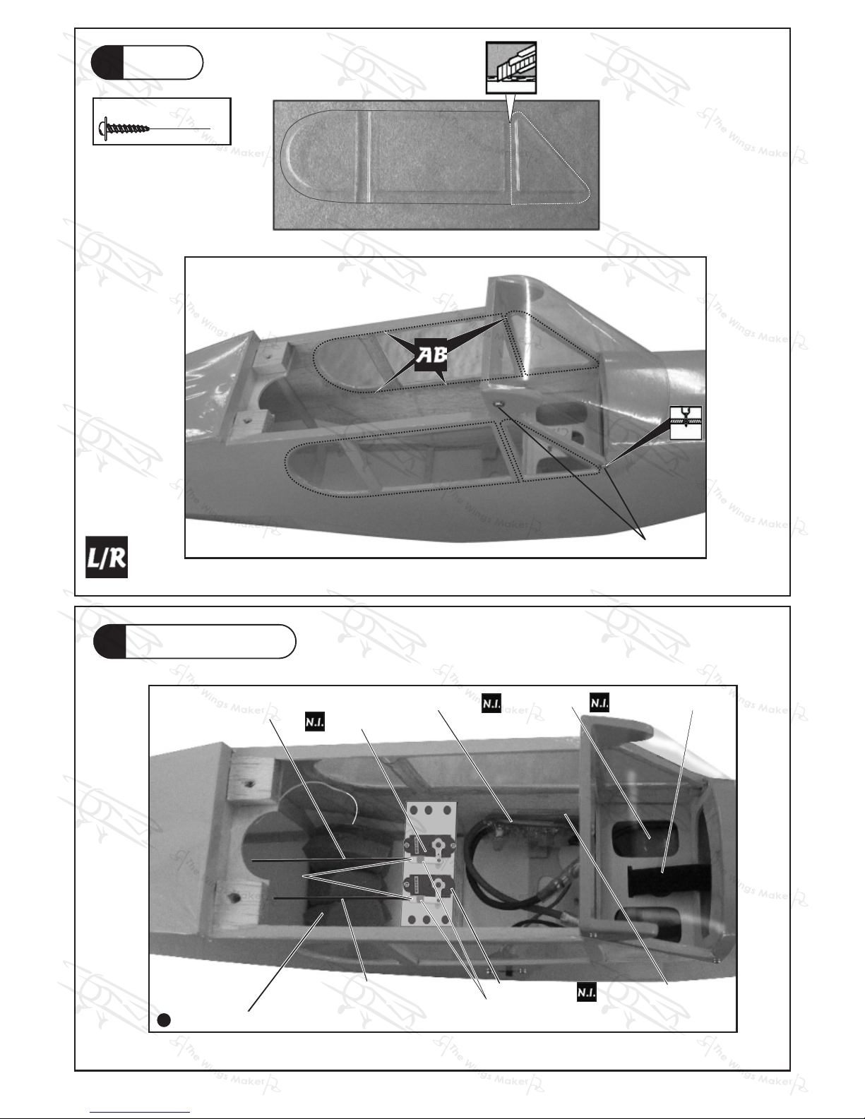
Canopy
PWA2 X 8mm Screw
4
10
PWA2 X 8mm
Radio Equipment
11
15A Spe ed C on tr ol le r
Battery
Double-Sided Tape
Battery Tie
1.5mm
Receiver wrapped up in sponge
Straper
Elevator Servo
Fuel Tube
d2xD4x4mm
Elevator Pushrod
Ø1.4x415mm
Rudder Pushrod
Ø1.4x420mm
Rudder Servo
Page 9
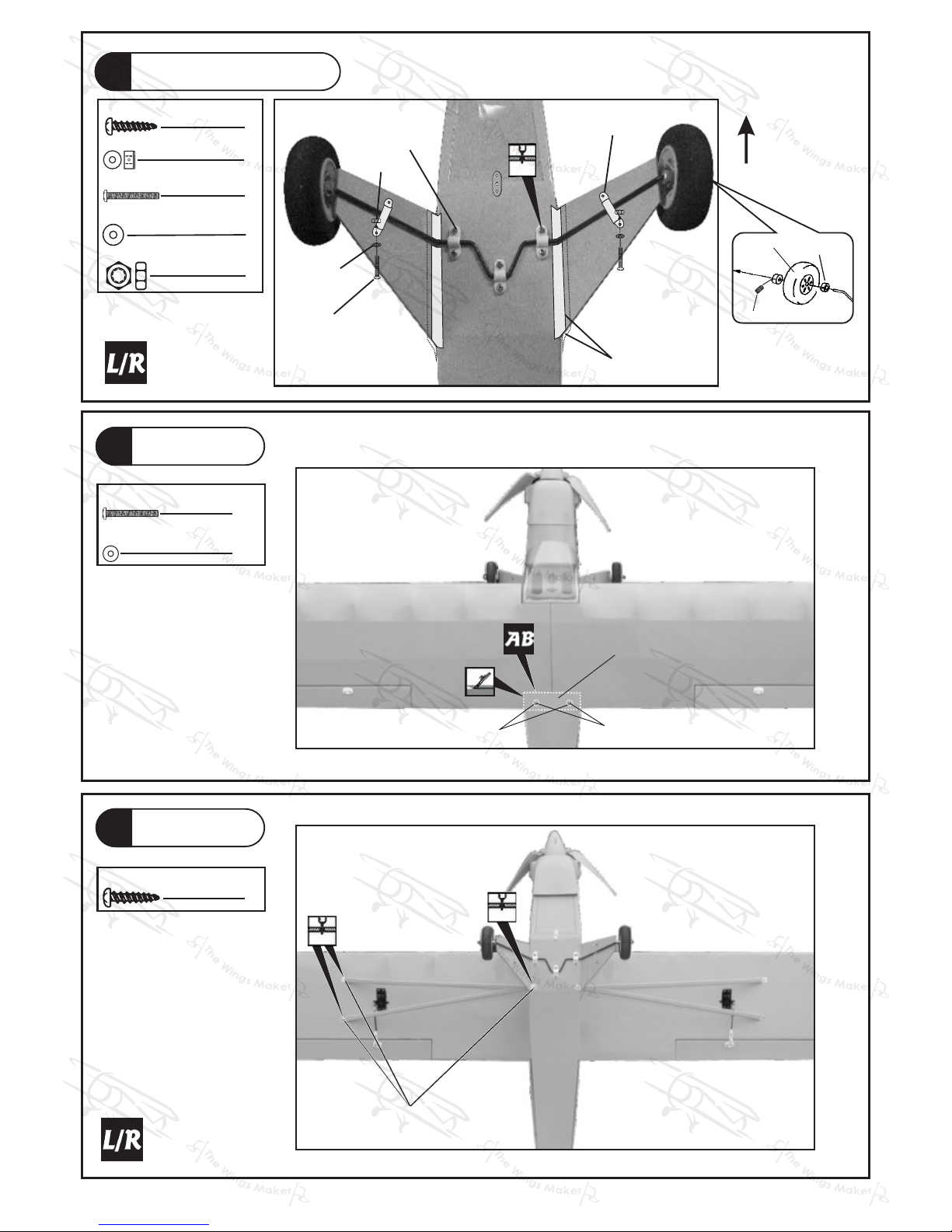
Wing Struts
Main Wing
14
13
6
2
PA2.3x8mm Screw
PM2.5x25mm Screw
Main Landing Gear
12
d2.6xD7mm Washer
2
PM2.5x2 5mm
d2.6xD7mm
Wing P rotection
PA2.3x8mm
1mm
1mm
PA2.6x10mm
PVC PLATE
1.5mm
M2 NUT
Washer
d2xD5mm
PM2x6mm
PA2.6x10mm Screw
2.6mm Collar
4
6
4
4
M2 NUT
4
3mm set screw
2.6mm colla r
Wheel Ø50mm
20x70mm
TRANSPARENT DECALS
Front
PM2x6mm Screw
d2xD5mm Washer
P.8
Page 10
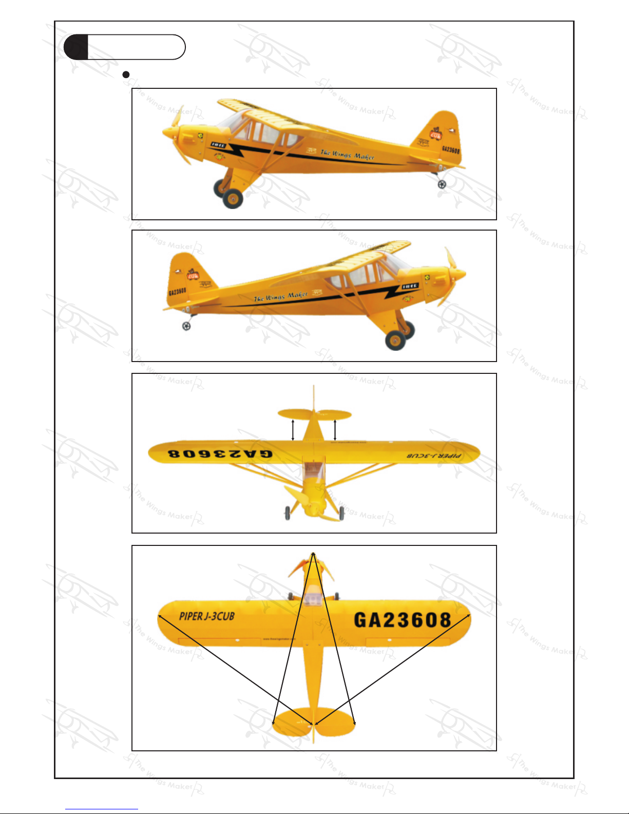
P.9
Wing Setting
15
A
A '
B
B '
C
C '
A =A ' B =B '
C =C '
Adjust the wing and fuselage configuration as shown in the diagrams.
Page 11
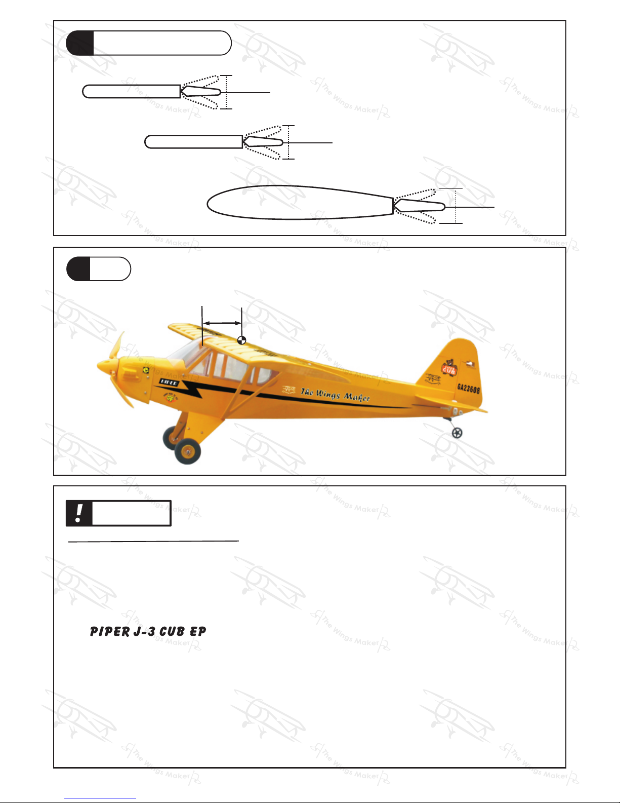
The ideal C.G. position is 50mm (2.0 in.) behind the leading edge
measured at where the wing meets the fuselage. In order to
obtain the C.G. specified, add weight to the fuselage or move
the battery position. Check the C.G. before flying.
50mm
C.G.
2.0in.
P.10
Elevator
Important Safety Precautions
Warning!
C.G.
17
Rudder
25mm
25mm
15mm
15mm
16
GE0160708
Aileron
10mm
10mm
Adjust the control throws as shown in the
diagram. These throws are good for general
flying. You can adjust according to your
personal preference.
Control Throws
#First time flyer should never fly by himself / herself. Assistance from experience d flyer is
absolutely necessary.
#Pre-flight adjustment must be done before flying, it is very dangerous to fly a badly
pre-adjusted aircraft.
# is specially designed to be powered by Speed 400 geared motor.
#Make sure the air field is spacious, never fly the plane too close to people and never get
too close to a running propeller.
#If you find wrinkles on the covering as a result of weather changes, you can use hot iron
to remove the wrinkles. Please begin with lower temperature setting and gradually raise
the temperature until the wrinkles are gone. Too hot an iron may damag e the covering .
#Chec k and re-tighten up all factory assembled screws, use thread locker if necessary.
Page 12
GE0160708
THE WINGS MAKER
www. thewingsmaker. com
 Loading...